Article

Experimental Study on Magnetic Resonant Coupling AC Magnetic Suspension Considering Electrical Power Transmission

Department of Mechanical Engineering and System Design, Saitama University, Saitama 338-8570, Japan
*
Author to whom correspondence should be addressed.
Actuators 2022, 11(8), 208; https://doi.org/10.3390/act11080208
Submission received: 23 June 2022 / Revised: 22 July 2022 / Accepted: 26 July 2022 / Published: 28 July 2022
(This article belongs to the Special Issue Magnetic Bearing Actuators II)

Abstract

:
A three-degree-of-freedom AC magnetic suspension system using magnetic resonant coupling was fabricated. The AC magnetic suspension system can produce restoring force without active control. This system is dynamically stabilized by adding indirect damping, which is produced by suspending to the stator with viscoelastic support mechanisms. A non-contact electrical power transmission is achieved simultaneously by magnetic resonant coupling. The structure of magnetic resonant coupling is similar to the structure of the transformer. The magnetic flux path for suspension is combined with that of electrical power transmission. The electric characteristics of the transformer depend on the resistance of a load connecting the secondary circuit. The measured results indicate that the driving frequency needs to be adjusted to achieve stable suspension in relation to the resistance of the load. These characteristics are confirmed experimentally.

1. Introduction

Magnetic suspension has a lot of advantages such as non-friction, no abrasion, less noise, less vibration, no lubrication required, high-speed performance and long-life characteristics [1,2]. It has been applied to railroad bogies for high-speed trains [3], bearings for high-speed-rotation turbo molecular pumps [4], artificial hearts [5], guides for high-speed elevators [6], gyroscopes [7], energy storage devices (flywheels) [8], contactless lamps [9], floating globe models [10], and so on. The magnetic suspension system using the attractive force of a DC electromagnet is inherently unstable. Therefore, in a typical magnetic suspension system, the displacement of a suspended object (floator) is detected with a sensor, and the coil current is adjusted based on the detected signal via a power amplifier by a feedback controller. Because the sensor and controller must be equipped, the active magnetic suspension system is costly. Meanwhile, the AC magnetic suspension system produces restoring force without active control [11,12,13]. It means that the AC magnetic suspension system can omit sensors and a controller, which leads to low cost. In addition, the reliability of the system is expected to be higher than an active system because the latter is weak to impulsive noises, and its risk due to failure in the components is higher. A typical AC magnetic system consists of a sinusoidal voltage generator for driving an electromagnet with a series-connected capacitor. The inductance of the stator circuit depends on the gap between the electromagnet and a magnetic target fixed to the floator. The restoring force is produced when the driving frequency is set to be slightly higher than the resonant frequency of the LCR circuit consisting of the electromagnet and the series-connected capacitor. This characteristic is called a self-stabilization characteristic in the following. To achieve dynamical stability, however, some damping mechanism is necessary [13].
In several applications, electric power transmission to the floator is required. Such examples are a floating lamp [9] and a carrier system without a contacted current collector represented by a trolley and pantograph [14]. There are several methods of electric power transmission to the floator. One method uses wire to the floator; another installs solar cells on the floator; another uses magnetic resonant coupling. In the first method, the non-contact property of magnetic suspension is lost due to the wires. In the second method, generated power is rather small per surface area. In addition, electric power generated by solar cells depends on the illuminance environment [14]. The third method has an advantage of highly efficient power transmission even if the gap is large [15]. Currently, a floating lamp that uses the magnetic resonant coupling wireless power transmission is commercially available [9].
The structure of the magnetic resonant coupling is similar to that of an electric power transformer that has primary and secondary coils. If the magnetic resonant coupling power transmission is simply installed in the conventional magnetic suspension, the system uses additional coils for power transmission. The authors have proposed a novel AC magnetic suspension using magnetic resonant coupling [16,17]. In the proposed system, the electromagnet for suspension operates as a primary coil for transmitting power, and the magnetic target attached to the floator has a secondary coil for receiving power. Therefore, no additional coil is necessary. In the following, the electromagnet for suspension fixed to the stator is called a primary electromagnet, and the magnetic target attached to the floator is called a secondary electromagnet. The electric characteristics of the electromagnet measured at the primary circuit depends on the resistance of load connected to the secondary circuit. When the resistance of the load is too small, the self-stabilization property is lost because the resonant frequency varies. However, if the driving frequency is adjusted in relation to load, the self-stabilized property will be recovered.
In this paper, a three-degree-of-freedom AC magnetic suspension system with a function of power transmission using magnetic resonant coupling is fabricated to demonstrate the principle. The self-inductance, equivalent resistance and mutual inductance of the electromagnets for magnetic suspension are measured. Frequency characteristics of the resonant circuit and several electric characteristics in levitation are also measured. The effects of the load resistances of the secondary circuit are studied as well.

2. Principle

2.1. AC Magnetic Suspension System

Figure 1 shows a schematic view of a conventional AC magnetic suspension system. The restoring force is produced according to the principle of the AC magnetic suspension system described in the following. Moreover, a damping effect is produced by the viscoelastic support mechanism suspending the stator from base.
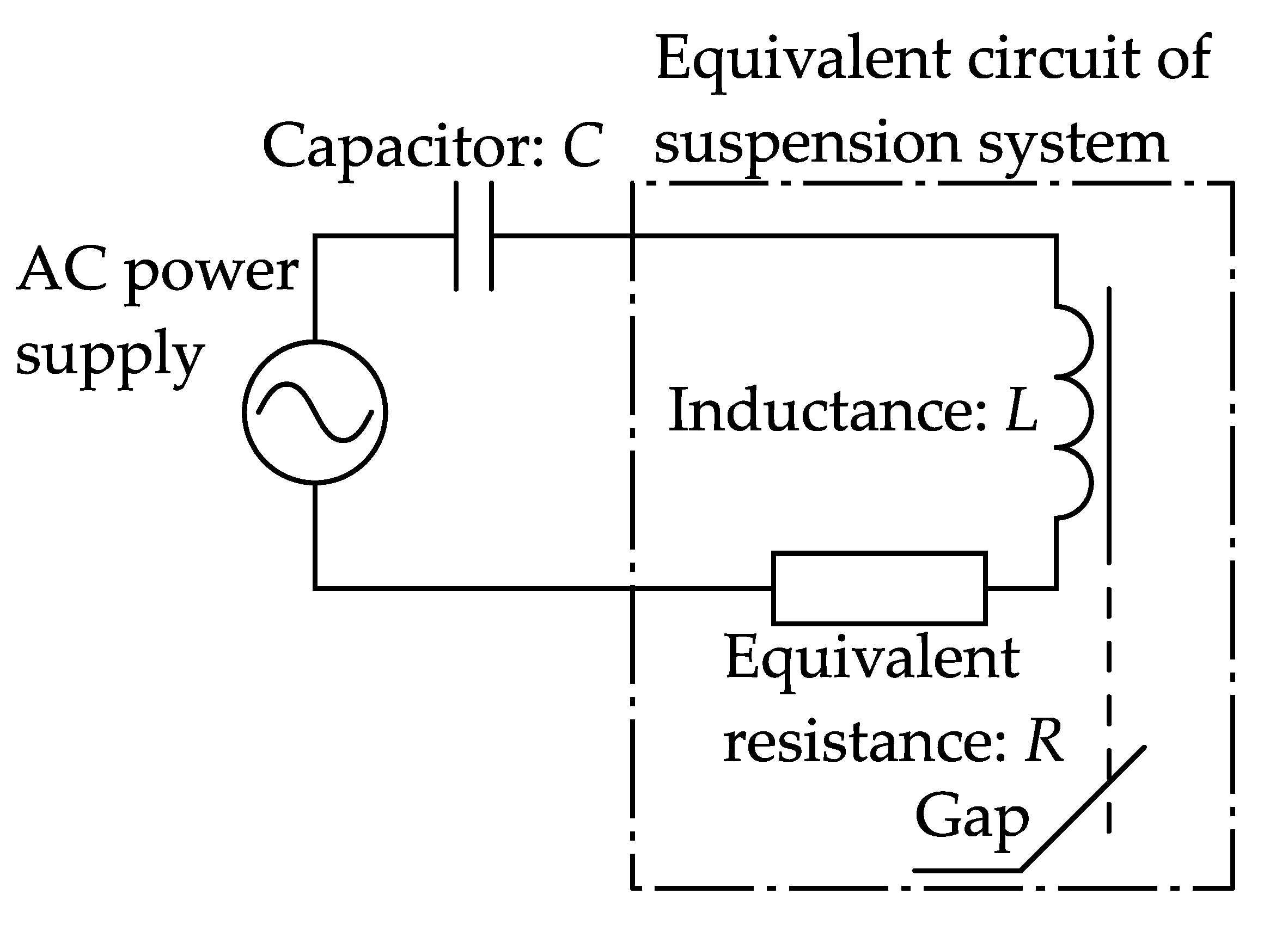
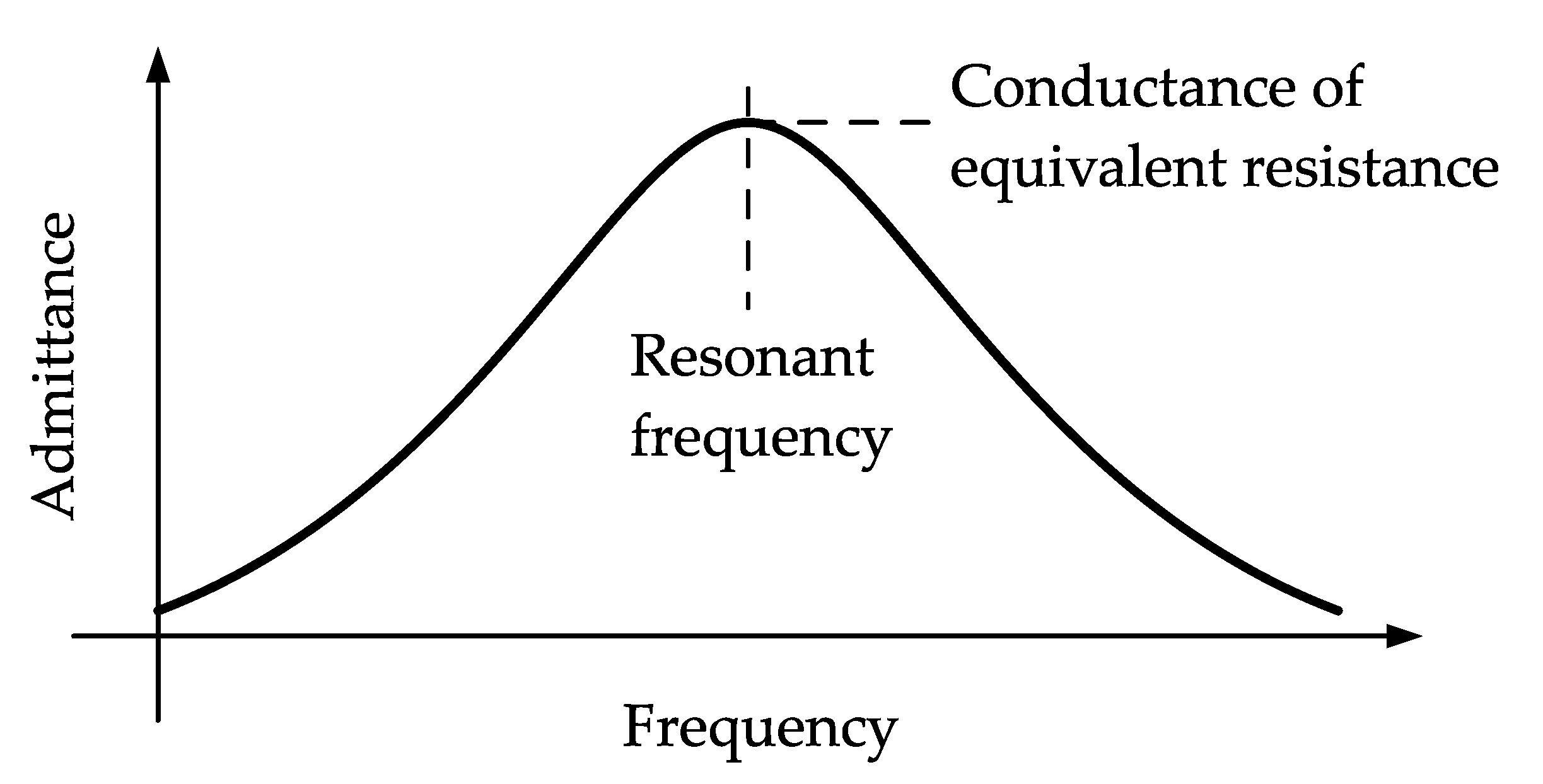
Here, the self-stabilization by the AC magnetic suspension is explained. An equivalent electric circuit of the AC magnetic suspension system is represented by a circuit diagram with an AC signal generator connected to an LC resonant circuit consisting of a capacitor, an inductor and an equivalent resistance, as shown in Figure 2. Figure 3 shows a schematic frequency characteristic of the admittance of the LC equivalent circuit. The admittance of the circuit has a peak at the resonant frequency of the LC circuit. The peak of the admittance equals the conductance of the equivalent resistance.
The magnetic circuit consisting of the electromagnet and its target is assumed to be ideal such as no leakage flux, no magnetic saturation, no hysteresis, and infinite magnetic permeability of iron cores. The inductance of the equivalent circuit is expressed by
L = μ 0 N 2 A D ,
where L: inductance of the equivalent circuit, N: number of electromagnet coil turns, μ0: magnetic permeability of air, A: cross-sectional area of electromagnet, and D: gap between the core of electromagnet and the magnetic target. Figure 4 shows a schematic view of the relation between the inductance and the gap indicated by Equation (1). The resonant frequency of the equivalent LC circuit is expressed by
f r = 2 π 1 L C ,
where C: capacitance. Figure 5 shows a schematic frequency characteristic of the admittance with respect to the gap. The inductance of the equivalent circuit decreases as the gap increases. Then, the resonant frequency of the equivalent LC circuit increases, and the coil current increases because the resonant frequency approaches the driving frequency. As a result, the attractive force acting on the floator increases when the gap increases and vice versa.
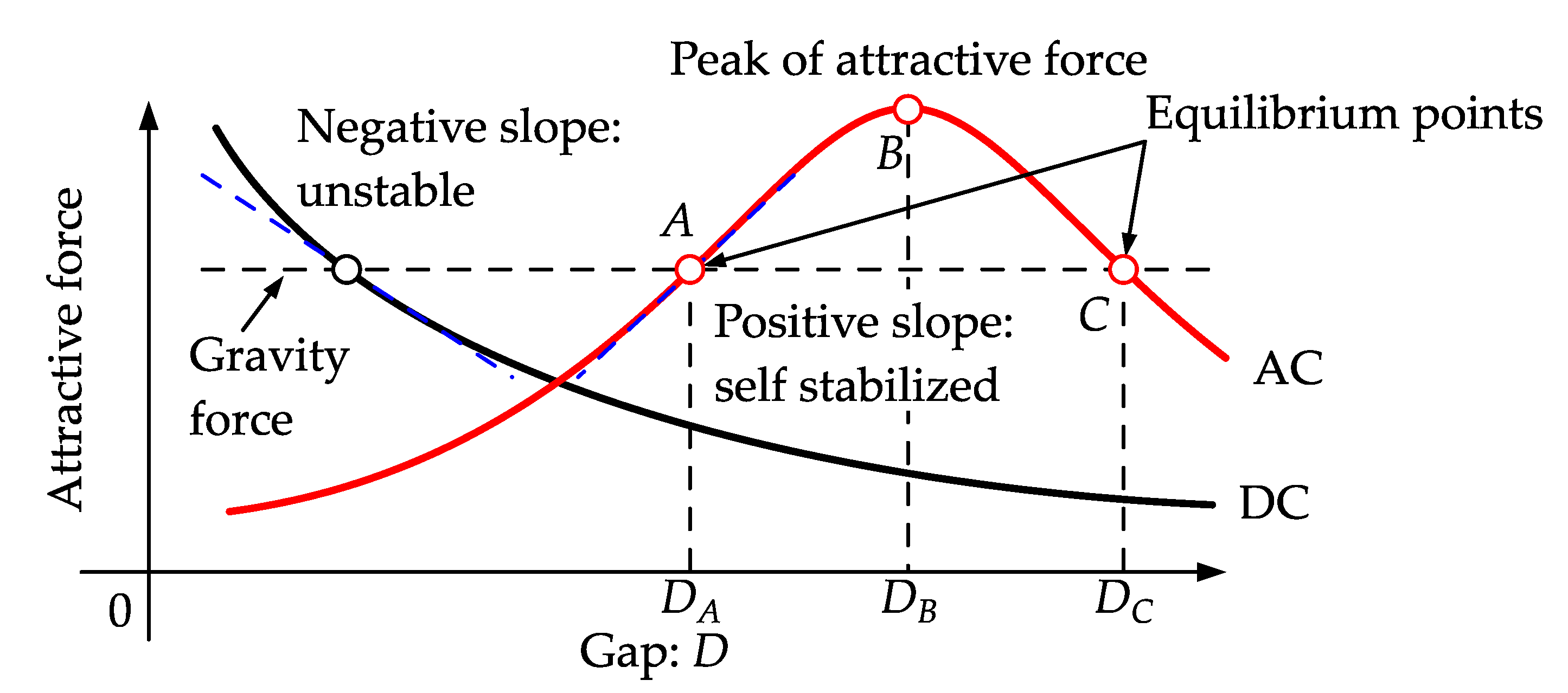
Figure 6 shows the schematic characteristics of the attractive force with respect to the gap in typical AC and DC magnetic suspension systems. In this figure, the slope indicates the stiffness of suspension. The schematic characteristic of the DC magnetic suspension is under a constant current condition (without control). The schematic characteristic of the AC magnetic suspension is under a constant-frequency and constant-amplitude sinusoidal voltage. The negative slope in the DC magnetic suspension system indicates instability. When the driving frequency is set to be slightly higher than the resonant frequency in the AC magnetic suspension system, the slope is positive at gaps less than DB, while it is negative at gaps more than DB. Therefore, the AC magnetic suspension system has a self-stabilization characteristic around the gap of DA. At gaps more than DB, the resonance frequency exceeds the driving frequency. Then, the stiffness of the suspension system becomes negative. However, the pulling force acts on the floator when DB < D < DC because the attractive force exceeds the gravity force. Therefore, the pull-in range is between 0 and DC.

2.2. Magnetic Resonant Coupling Electric Power Transmission

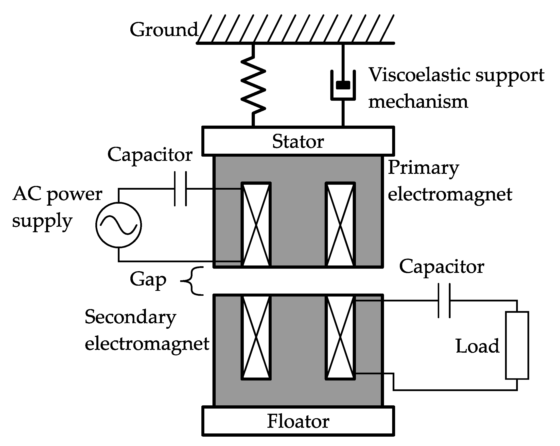
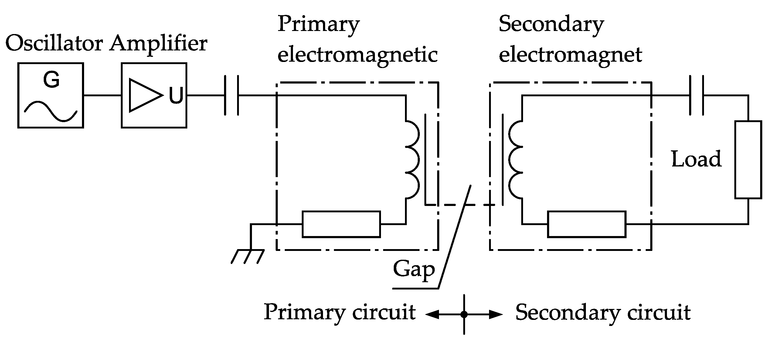
Figure 7 shows a basic configuration of an AC magnetic suspension using magnetic resonant coupling. Figure 8 shows its equivalent circuit diagram. This method is one of the power transmission methods using mutual induction of transformer that can transmit power with a high efficiency across a wide gap. In the fabricated apparatus, the primary electromagnet has two functions of an actuator for generating suspension force and an antenna for power transmission as the primary coil of a transformer. The secondary electromagnet fixed to the floator consists of an iron core and a receiving antenna for power transmission as the secondary coil of the transformer and for generating attractive force by the primary electromagnet. In the following, the circuit consisting of the oscillator, the amplifier, the capacitor, and primary electromagnet is called the primary circuit. The circuit consisting of the secondary electromagnet, the capacitor and a load is called the secondary circuit. When the load in the secondary circuit changes, the secondary current changes. It also changes the voltage induced in the primary circuit due to mutual induction. As a result, the phase and amplitude of the primary current changes.
The efficiency of power transmission depends on the inductive coupling factor k [18], which is given by
k = M L 1 L 2 ,
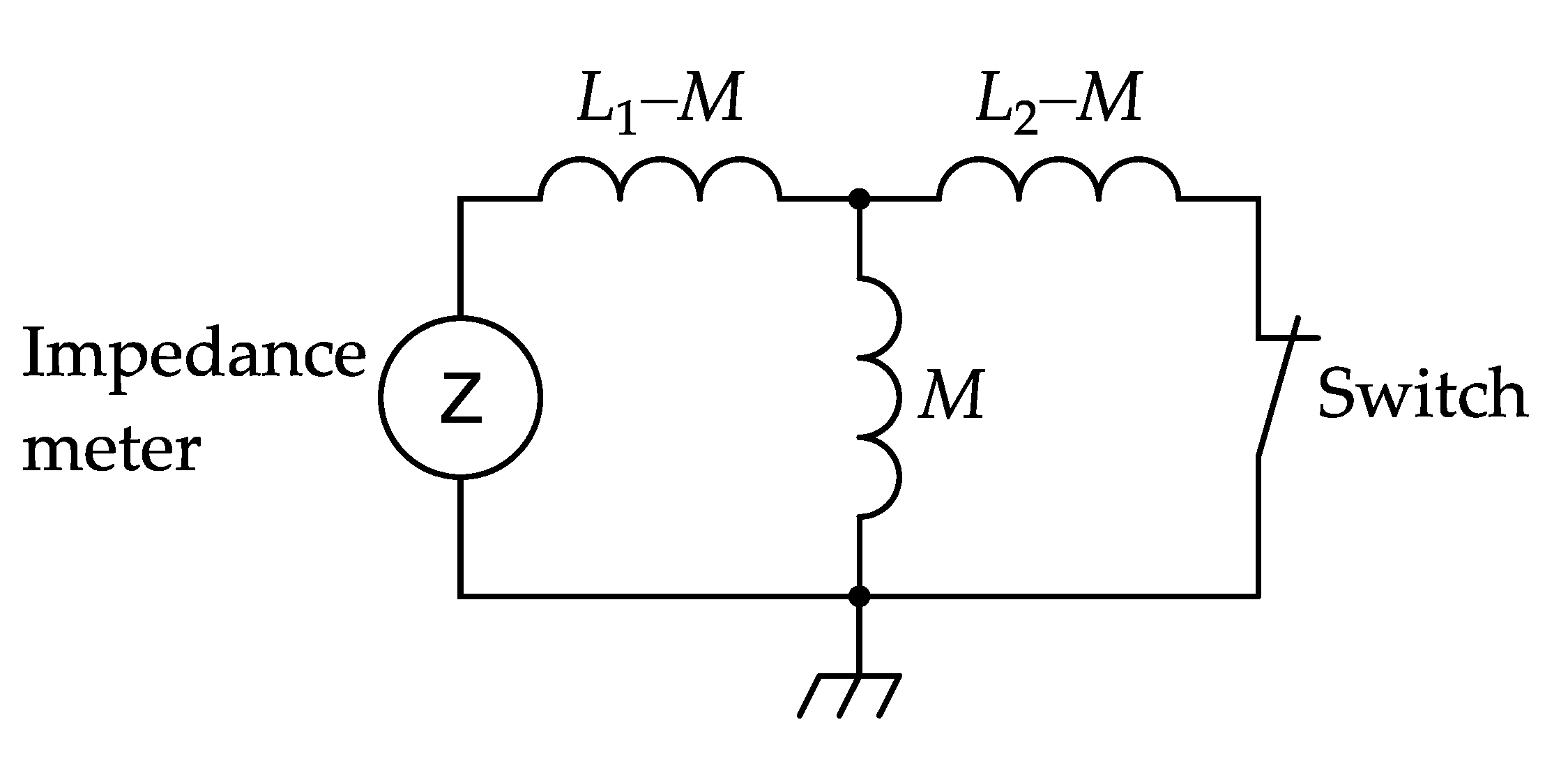
where L1: primary self-inductance, L2: secondary self-inductance and M: mutual inductance. The primary and secondary self-inductances can be measured directly. For measuring the mutual inductance, the transformer is approximated as a T-shape equivalent circuit shown by Figure 9. The mutual inductance of the transformer can be estimated from the primary inductances when the secondary circuit is open and closed. The mutual inductance of M is given by
M = L 1 L 2 L s L 2 ,
where Ls is the measured inductance of the primary coil when the switch is closed.

3. Experimental Setup

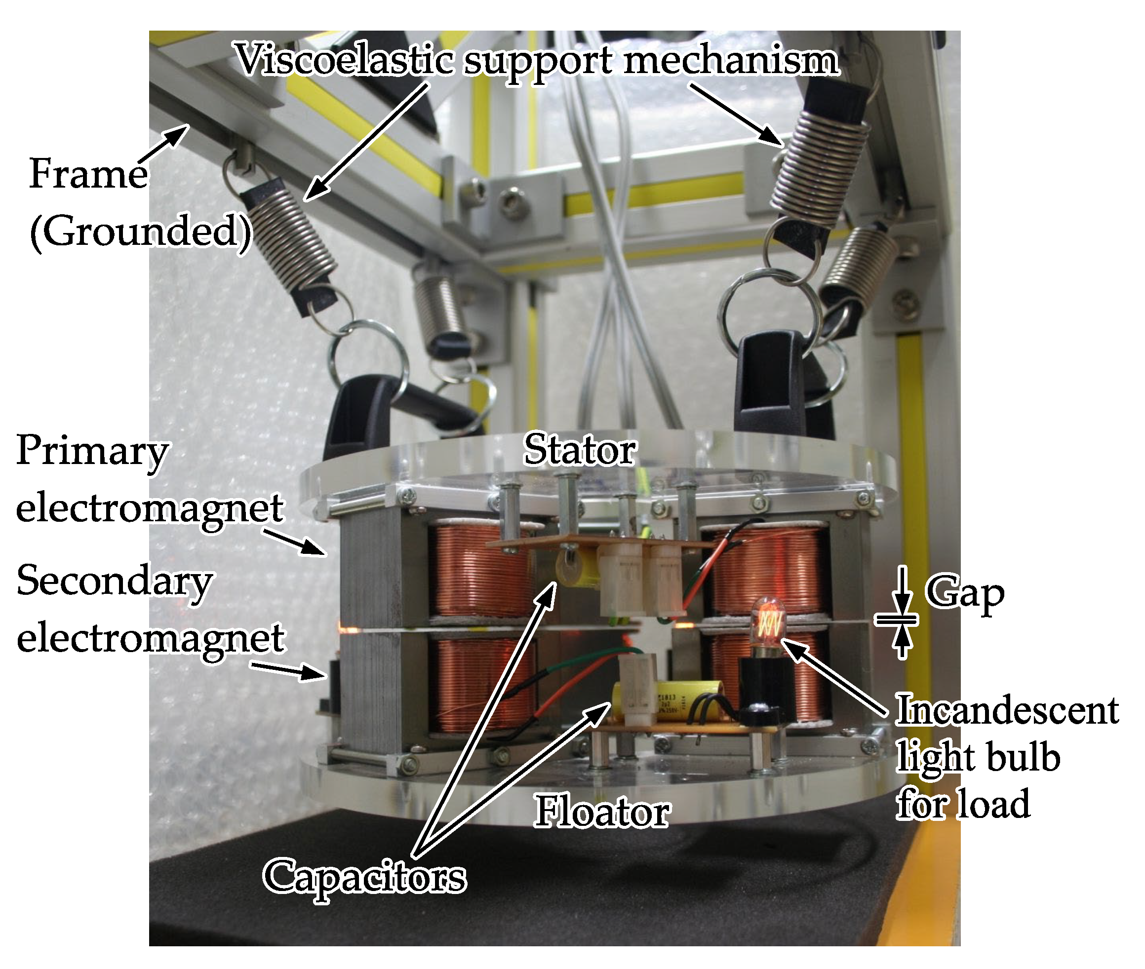
Figure 10 shows a photograph of the fabricated AC magnetic suspension apparatus. The apparatus consists of a grounded frame, four viscoelastic support mechanisms, a circular stator with three primary electromagnets connected with capacitors, and a circular floator with three secondary circuits. The diameter and thickness of the stator is 200 mm and 10 mm. The floator has the same size. The stator can be held at the attached handles on the top. Four viscoelastic support mechanisms, each of which consists of a coil spring and a rubber, are installed between the handle and the grounded frame. The stiffness and the damping coefficient of the support mechanism are approximately 20 kN/m and 90 N s/m, respectively. The core of the primary electromagnet is E-shaped with a size of 58 × 39 × 35 mm. The E-shaped core is made of laminated silicon steel plates. Laminated silicon steel plates have high permeability, high magnetic saturation, and low cost. The core of the secondary electromagnet is same as the primary electromagnet. The coils of primary electromagnets and secondary electromagnet are manufactured for the DC resistance to be 1.2 Ω. Therefore, there are slight differences among the number of turns. It may cause the inductances to be different for each electromagnet. The capacitances listed in Table 1 were selected to minimize the differences among the resonant frequencies. However, there remained differences in characteristics among the electromagnets.
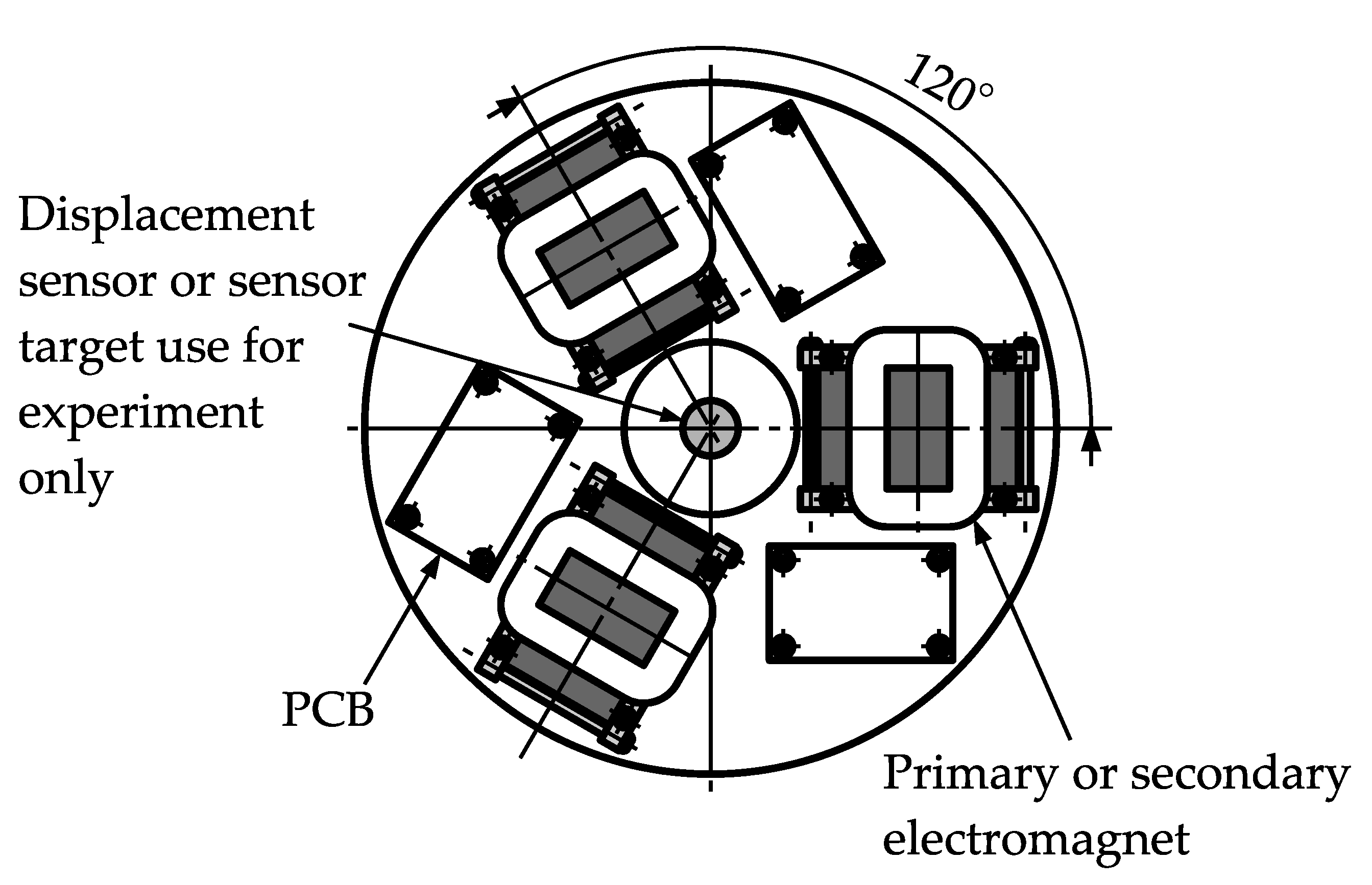
Figure 11 shows a layout of the stator with the primary electromagnets and the floator with the secondary electromagnets. Three pairs of primary and secondary electromagnets are located at the vertices of an equilateral angle. These pair of electromagnets are called pair number 1 to 3 in the following. Three printed circuit boards (PCBs) are installed on the underside of the stator and on the floator. The capacitors for the primary circuit are installed in the PCBs on the stator. The capacitors for the secondary circuit are installed in the PCBs on the floator. In the apparatus shown by Figure 10, incandescent light bulbs are used as the load of the secondary circuit. In the following experiments, an external resistor is used as load instead of the incandescent light bulbs. In the following experiment of displacement measurement, a sensor and its target are installed at the center of the stator and that of the floator temporarily. Each pair of AC magnetic suspension is operated individually. The translational motion between the stator and the floator in the vertical direction and the rotational motions around the two horizontal axes are stabilized by the AC magnetic suspension. The translational motions in the two horizontal directions and a rotational motion around the vertical axis are stabilized by the edge effects between the primary and secondary electromagnets. All the restoring force and torques are produced passively. The damping effects for the floator are produced indirectly by the stator supporting viscoelastic rubbers.
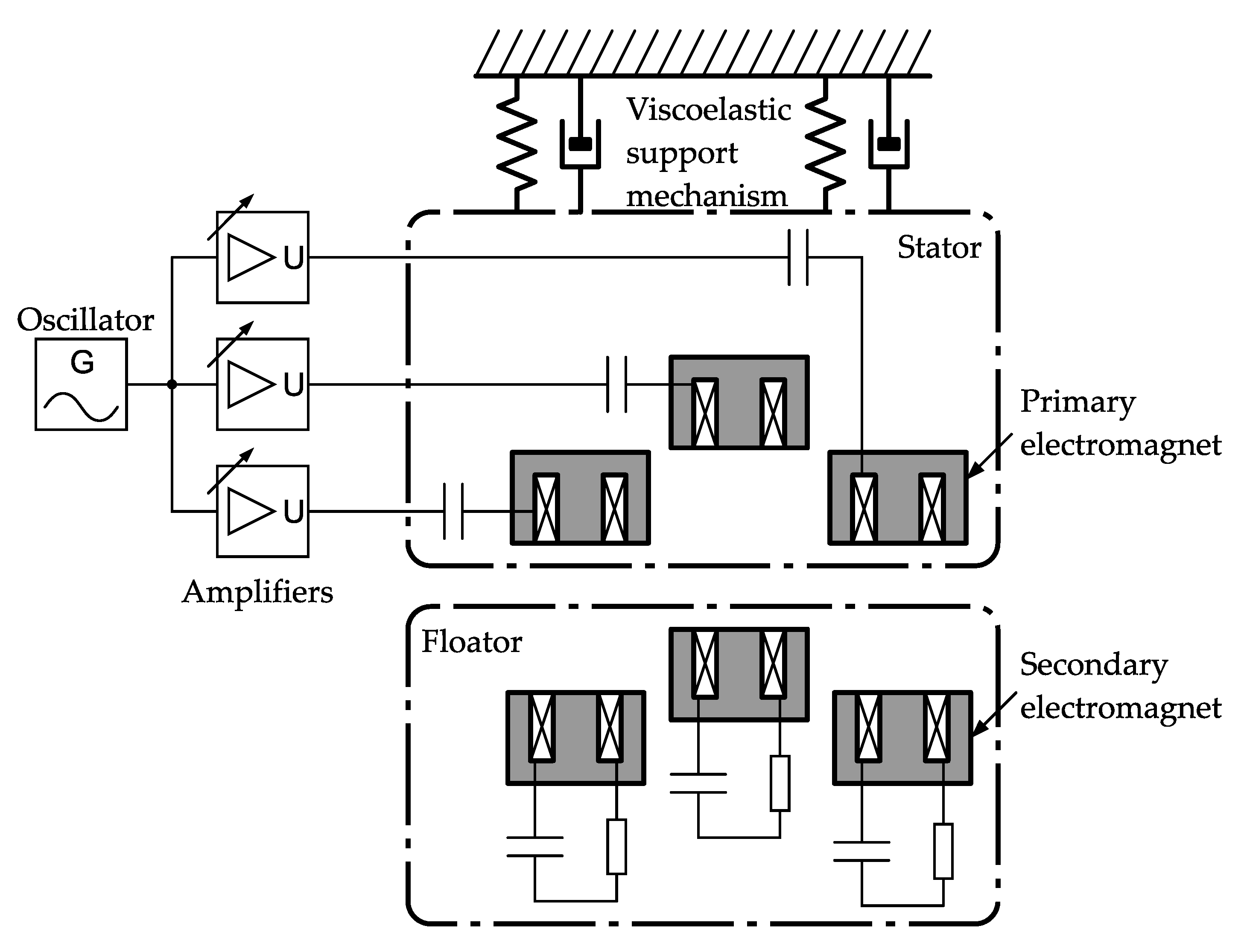
Figure 12 shows a schematic view of the experimental setup representing the electric circuit diagram and the mechanism. In the experiment, the oscillator generates a sinusoidal wave of 800 Hz with a constant amplitude of voltage. The gain of each amplifier is adjusted manually for the floator to remain horizontal. The output voltage and current of each amplifier are around 90 to 100 V0-p and the 1.0 to 1.6 A0-p, respectively. The gap between each primary electromagnet and the corresponding secondary electromagnet is around 0.4 mm.

4. Experimental Results

4.1. Electric Characteristics

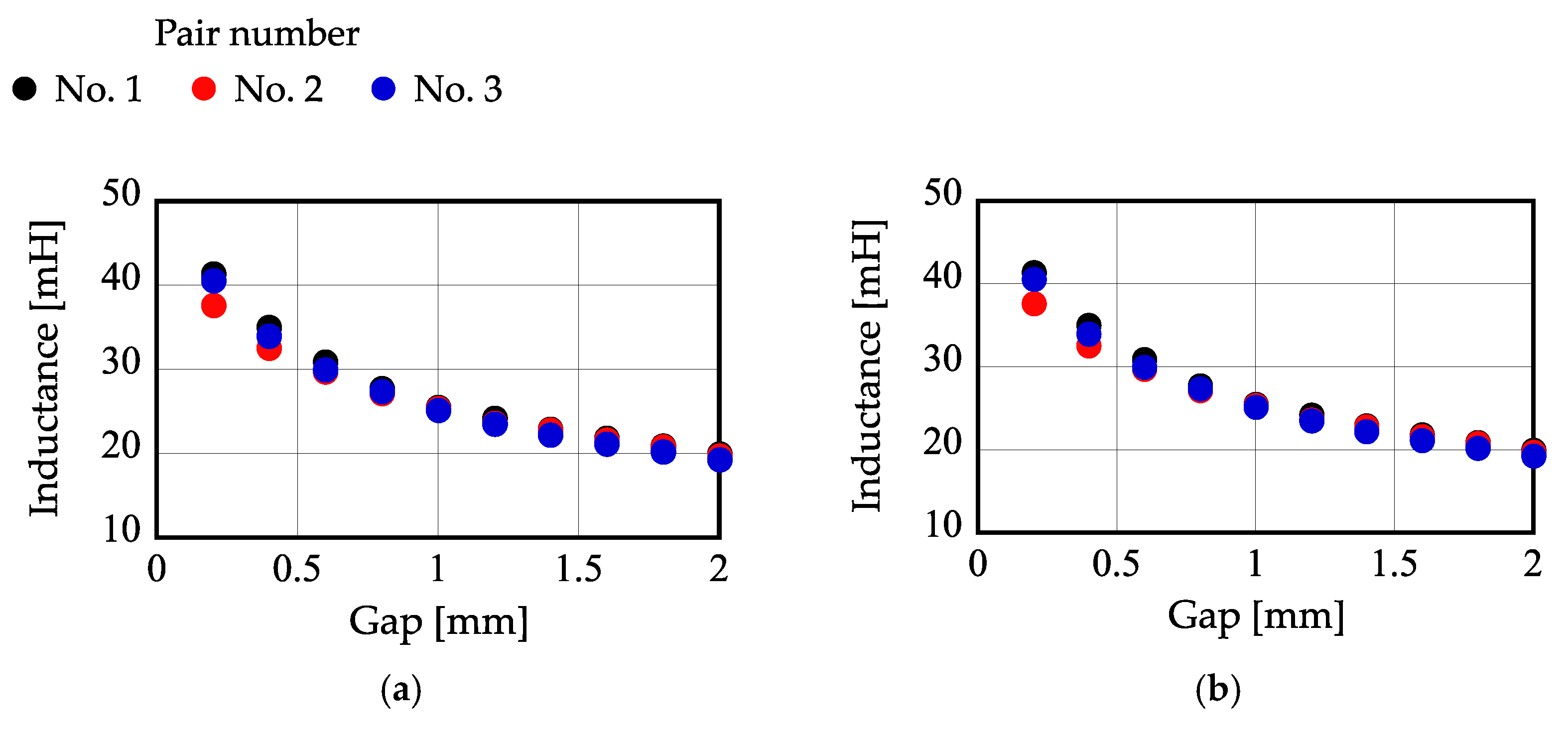
Figure 13 shows the self-inductance of each electromagnet measured at various gaps at the driving frequency (800 Hz) with an LCR meter. These results demonstrate that the inductance decreases as the gap increases, and the difference among the inductances is less than ±3%.
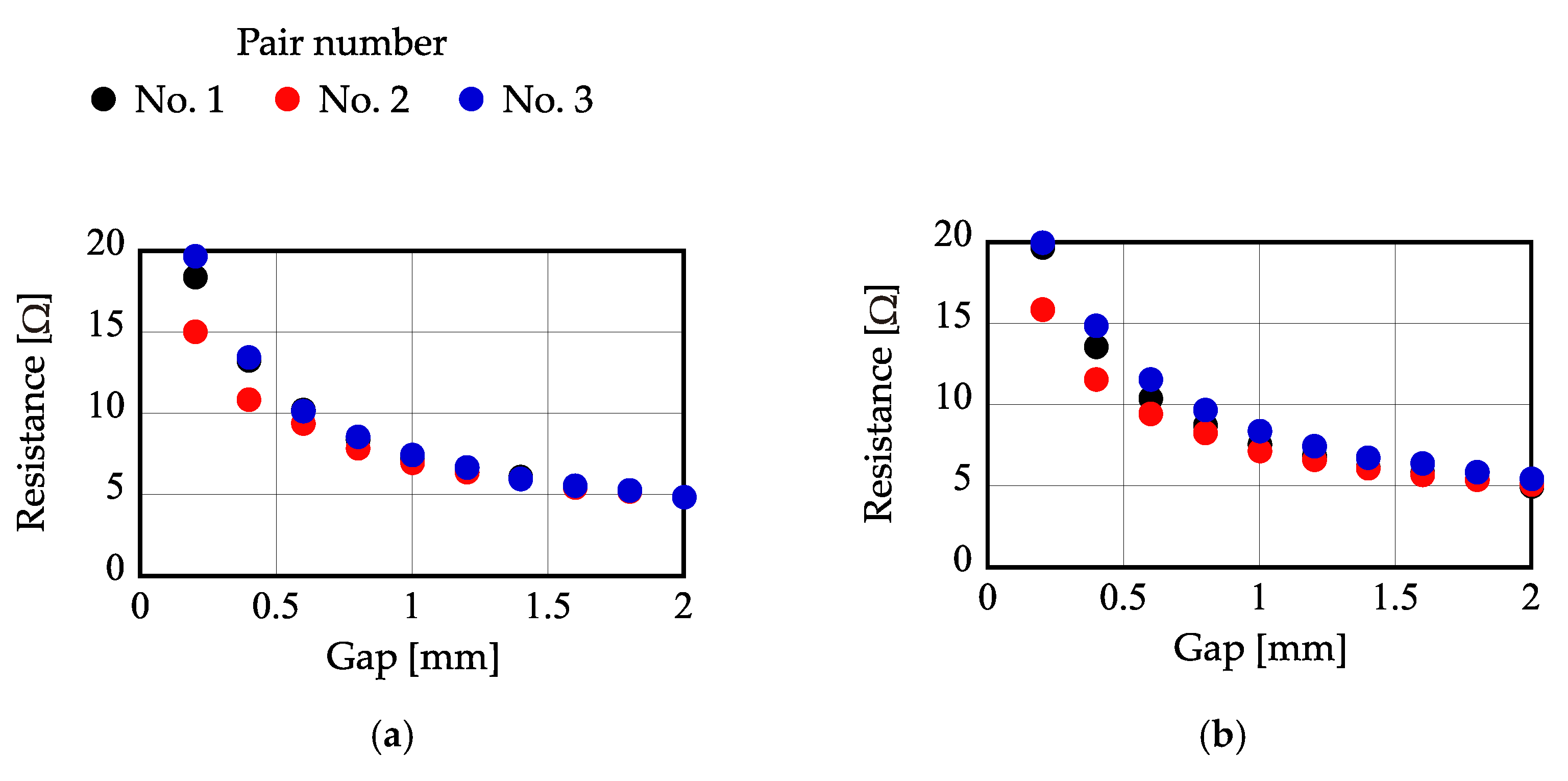
Figure 14 shows the equivalent resistance of each electromagnet measured at various gaps. Although the DC resistance is 1.2 Ω, the measured resistance is several times larger than this value. The equivalent resistance tends to increase as the gap decreases. It is expected that the equivalent resistance increases due to the eddy current.
Figure 15 shows a relationship between the estimated mutual inductance and the gap. The mutual inductance was estimated by comparing the self-inductance of the primary coil measured when open with that when closed. The coupling coefficient of the transformer is 81% at the smallest gap and 58% at the gap of 2.0 mm.
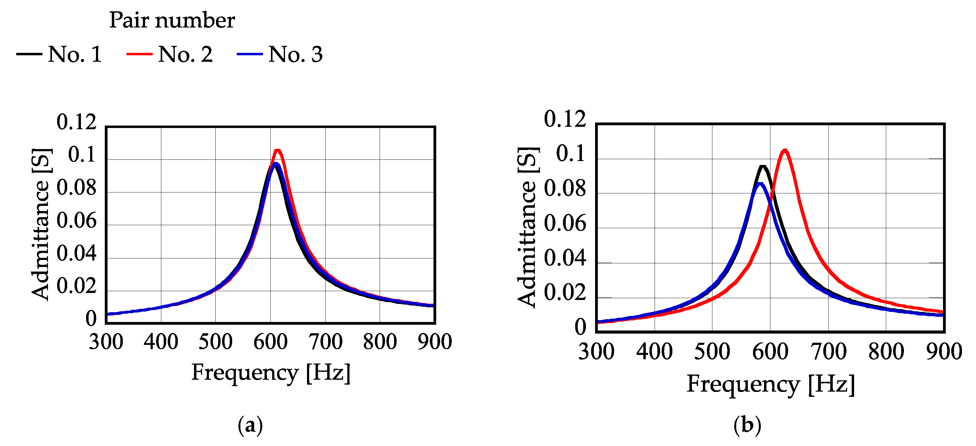
Figure 16 shows the calculated frequency characteristics of the admittance of a circuit combining an electromagnet and a capacitor at the gap of 0.6 mm. In calculating, the equivalent resistance value is used. There are some differences in characteristics among the pairs. Therefore, the voltages applied to the primary electromagnets will be adjusted individually to make the floator horizontal in levitation.
Figure 17 shows a frequency characteristic of the admittance of the number 1 electromagnet with respect to the load resistance when the gap is fixed to 0.6 mm. They were measured by an impedance analyzer. The peak of the admittance decreases as the load resistance decreases. When the load resistance is large (> 200 Ω), the characteristics can be approximated as a simple LCR circuit. When it is small (< 200 Ω), an anti-resonance characteristic due to the transformer appears.
Figure 18 shows a frequency characteristic of the admittance of the pair number 1 electromagnet with respect to the gap. When the load resistance is large (Figure 18a–c), the admittance of circuit at the driving frequency increases as the gap increases when the gap is less than 2.8 mm. When the gap is larger than 2.8 mm, the admittance decreases as the gap increases. The characteristic indicates that the magnetic suspension system can be stabilized when the gap is less than 2.8 mm.
Table 1 shows the measured capacitance values. The capacitors were selected for their resonance frequencies to be close to each other.
In Figure 18d,e, an anti-resonance characteristic due to the transformer can be observed. In the case of the anti-resonance characteristics, the admittance at the driving frequency decreases as the gap increases. The characteristic indicates that the magnetic suspension system becomes unstable when the driving frequency is set to be 800 Hz. Two resonance peaks appear on the higher and lower side bands of the anti-resonance frequency when the load resistance is small. Therefore, the system can be expected to obtain self-stabilization by adjusting the driving frequency.
Figure 19 shows a relationship between the gap and the admittance of the pair number 1 electromagnet at the driving frequency of 800 Hz for various load resistances. They were measured by an LCZ meter. The positive slope of an admittance–gap curve indicates that the current increases as the gap increases and vice versa. It contributes much to self-stabilization. However, if the current is constant, the attractive force decreases as the gap increases, which is a typical characteristic of magnetic force. It produces negative stiffness that is against self-stabilization. To examine the self-stabilization, both effects must be considered. This is the reason why the self-stabilization was not achieved when the load resistance was 100 Ω or 200 Ω. When the load is 20 Ω and 0 Ω, the slope is negative. Therefore, the system is unstable. These characteristics indicate that the stiffness and the maximum attractive force of the AC magnetic suspension system depends on the load.
It is expected from these experiments that the self-stabilization is achieved when the load resistance is larger than several hundred Ω.

4.2. Levitation Characteristics

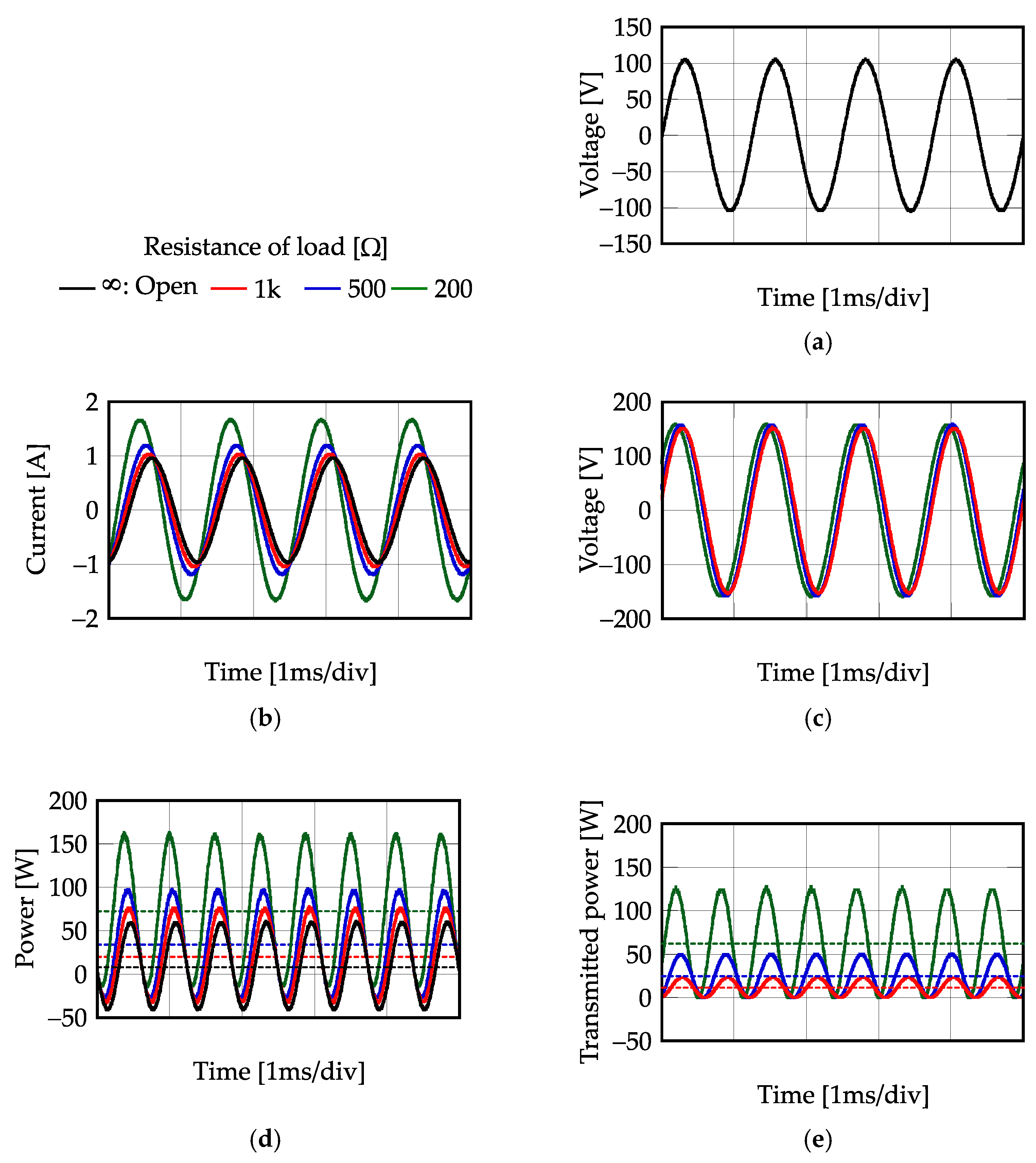
The voltages applied to the primary electromagnets were adjusted individually to keep the floator in a horizontal position. An eddy current displacement sensor was attached to the center of the stator and the sensor target was attached to the center of the floator to observe the displacement in levitation. Figure 20 shows time histories in the steady state when the floator levitates with a load resistor connected to the secondary circuit. Figure 20a–e are electric characteristics of the pair number 1 electromagnet. In the experiment, the load resistance was infinity (open circuit), 1 kΩ, 500 Ω or 200 Ω.
A constant-amplitude voltage was applied to the primary electromagnet as shown by Figure 20a. Figure 20b,c represent the measured time histories of the current of the primary circuit and the voltage induced in the secondary circuit, respectively. The voltage of the secondary circuit is almost constant regardless of load resistance.
Figure 20d represents the power of the primary circuit. Power was calculated by multiplying the voltage (shown in Figure 20a) by the current (shown in Figure 20b) of the primary circuit. Dashed lines represent the average powers; these are the active power. The average values indicate the active input power. Figure 20e represents the transmitted power to the secondary circuit. The transmission power was calculated by squaring the voltage in the secondary circuit and dividing it by the load resistance value. Dashed lines represent the average consumption power. Table 2 shows a relationship between the active input power and the transmitted power with respect to various load resistances. The whole active input power is the sum of the active power for the magnetic suspension and the consumption power at the load resistance. The whole active input power increases when the resistance of the load decreases. However, the power consumption for the magnetic suspension is almost constant at 10 W per one pair of electromagnets. In the AC magnetic suspension system, iron losses due to eddy current and hysteresis are generated. Therefore, the AC magnetic suspension system tends to have more consumption power than the typical DC magnetic suspension system.
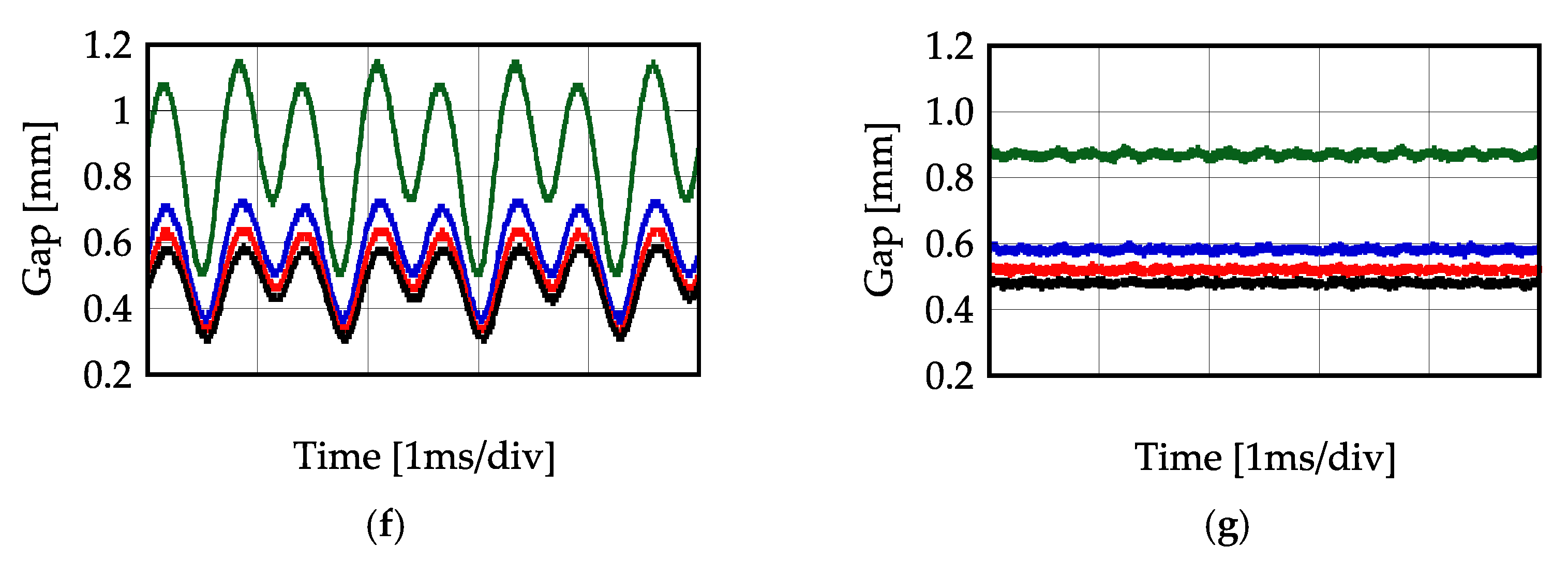
Figure 20f represents the signal of the displacement sensor. The signal incudes large vibratory components, in which components at the driving frequency and the secondary harmonic are dominant. However, such vibration could not be observed visually nor by a sensation of touch. The vibratory components are considered to be induced by the AC driving signal in the electromagnets.
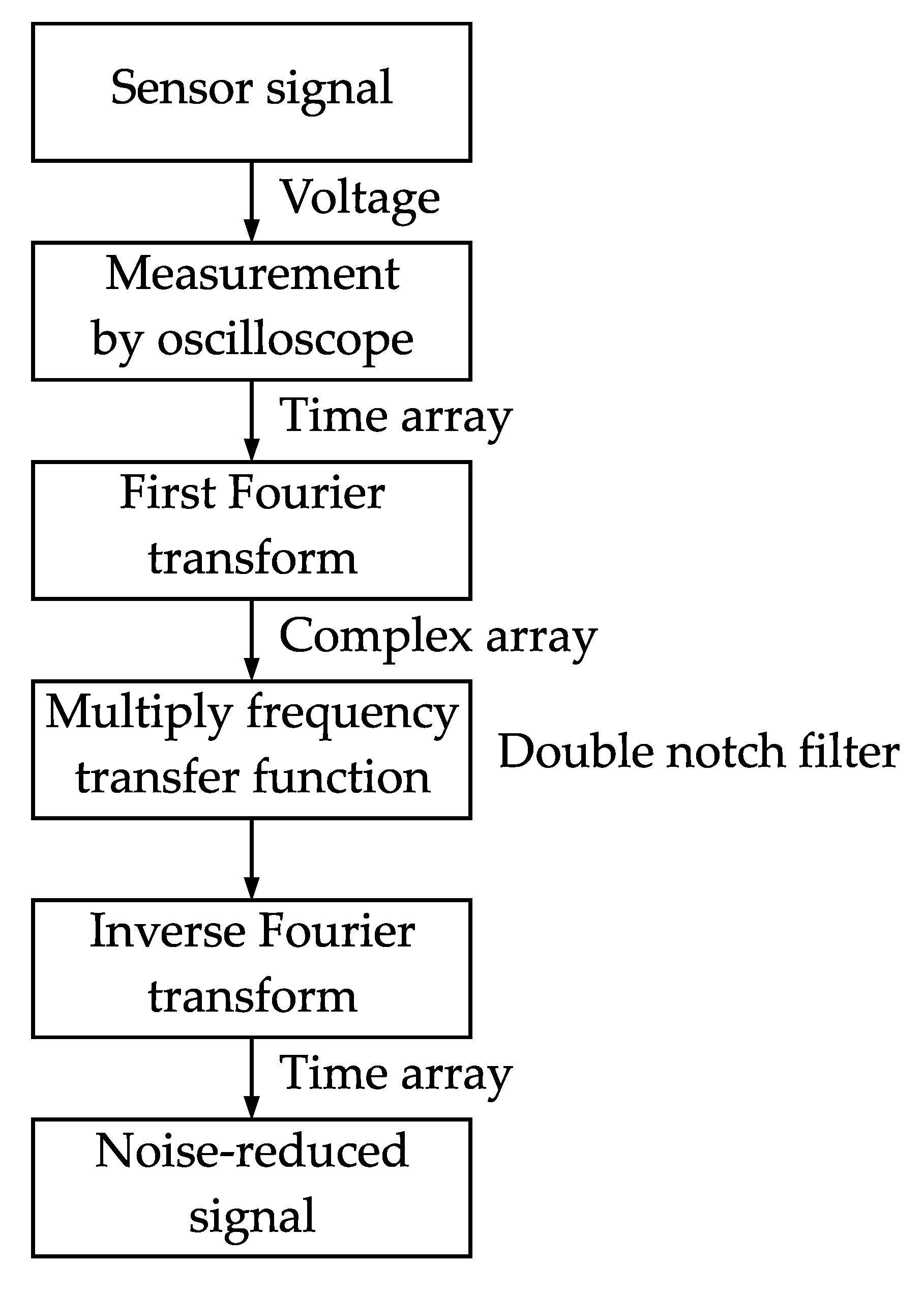
The gap is measured by an eddy current sensor. The eddy current sensor is installed on the stator near the electromagnets. Therefore, vibratory components were induced electromagnetically. To see the actual motion of the floator, the signal was processed by using Johnson’s method [19]. The flowchart of the method is shown in Figure 21.
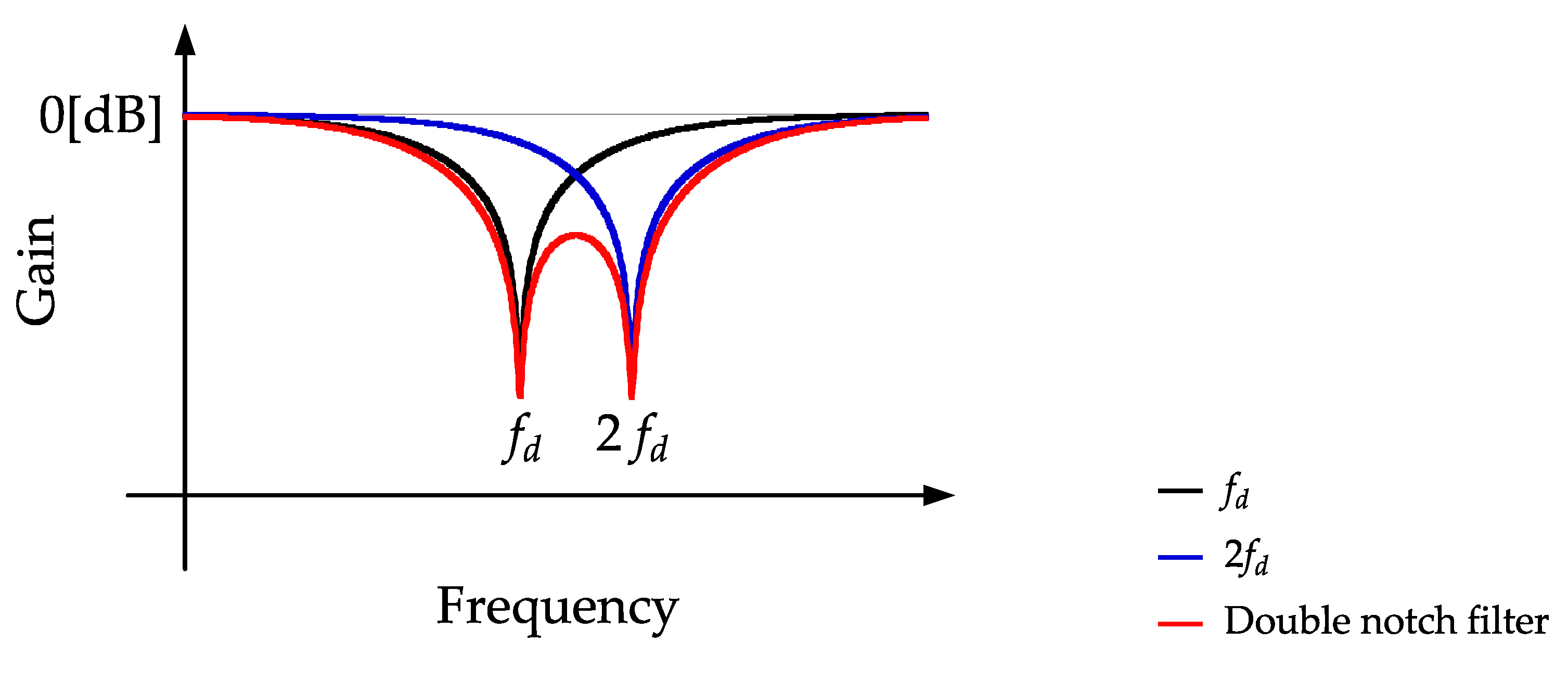
The measured time–history signal is converted to a complex array of each frequency by a fast Fourier transform. The complex arrays are multiplied by a frequency transfer function to be processed. Here, as shown in Figure 22, the frequency transfer function is a double-notch filter whose rejection frequencies are set to the driving frequency and its twice frequency. The time history is reobtained by an inverse Fourier transform using the complex array multiplied the frequency transfer function. The transfer function of the double-notch filter is given by
G ( s ) = s 2 + 0.02 ( 2 π f d ) s + ( 2 π f d ) 2 s 2 + 2 ( 2 π f d ) s + ( 2 π f d ) 2 s 2 + 0.02 ( 4 π f d ) s + ( 4 π f d ) 2 s 2 + 2 ( 4 π f d ) s + ( 4 π f d ) 2 ,
where fd represents the driving frequency.
Figure 20g shows the result of the noise elimination. From these results, the floator keeps the position, which indicates stable levitation. The floating gap increases when the load resistance decreases.
Figure 23 shows a static characteristic of the gap with respect to the load resistance when a downward disturbance is applied to the floator. The load resistance was infinite (open circuit), 1 kΩ or 500 Ω. The downward disturbance was generated by an additional mass. The additional mass is 102 g per one, which corresponds to a downward force of 1 N. When the amplitude of voltage is constant, the levitation gap varies due to the load resistance and the additional mass. The amplitude of the primary voltage is adjusted to keep the gap constant when no downward force is applied. The stiffness decreases as the load resistance increases. It is cancelled by the increase in stiffness due to the amplitude increase in the applied voltage. Therefore, the stiffness of the suspension is almost constant. From Figure 23, the stiffness of the suspension is approximately 10 to 50 kN/m independently of the load resistance when the downward force is applied from 0 to 10 N. From the results, the stiffness of the suspension is almost constant.
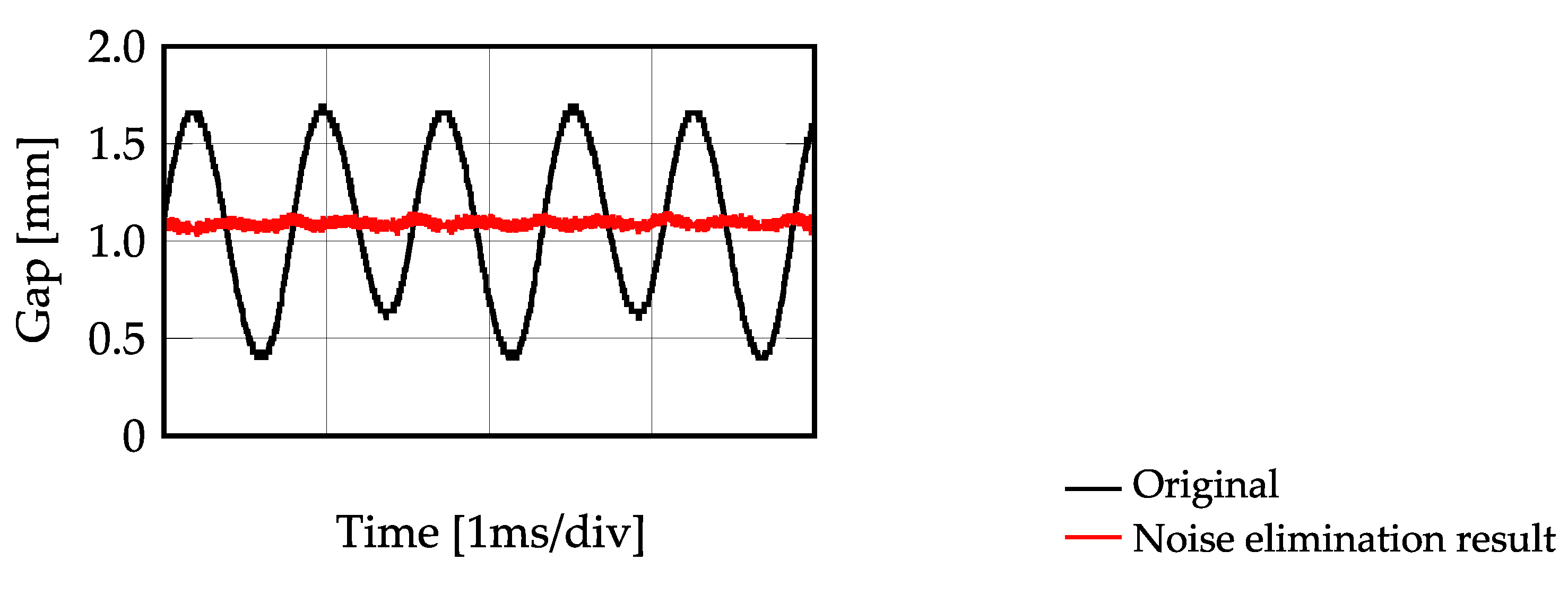
Figure 24 shows a time history of the gap when the secondary circuit is close (the load resistance is 0 Ω). In this case, the floator cannot obtain self-stabilization when the driving frequency was 800 Hz. When the driving frequency is set to be 650 Hz, the system achieves stable levitation. The black solid line represents an original sensor signal and a red solid line represents the noise-eliminated signal. This result indicates that self-stabilization can be achieved by adjusting the driving frequency with respect to load.

5. Summary

An AC magnetic suspension system using magnetic resonance coupling was fabricated. The fabricated system achieved non-contact suspension and power transmission to the floator simultaneously. The electrical characteristics and the suspension characteristics were studied experimentally. The characteristics of levitation and power transmission depend on the load resistance and suspension gap. The electric characteristics of the electromagnet depend on the resistance of the load connected to the secondary circuit. Therefore, the driving frequency must be adjusted to achieve stable suspension in relation to the resistance of the load. These characteristics were confirmed experimentally.

Author Contributions

Conceptualization, Y.I. and T.M.; Methodology, Y.I. and M.T.; Hardware, Y.I.; Formal analysis, Y.I. and M.T.; Project administration T.M.; Writing-draft Y.I.; Writing—Review and editing T.M. and M.T.; Administration, T.M.; Funding acquisition, T.M. and M.T. All authors have read and agreed to the published version of the manuscript.

Funding

This research received no external funding.

Institutional Review Board Statement

Not applicable.

Informed Consent Statement

Not applicable.

Data Availability Statement

Not applicable.

Conflicts of Interest

The authors declare no conflict of interest.

References

  1. Jayawant, B. Electromagnetic suspension and levitation. IEE Proc. A Phys. Sci. Meas. Instrum. Manag. Educ. Rev. 1982, 129, 549–581. [Google Scholar] [CrossRef] [Green Version]
  2. Bleuler, H. A Survey of Magnetic Levitation and Magnetic Bearing Types. JSME Int. J. Ser. 3 Vib. Control Eng. Eng. Ind. 1992, 35, 335–342. [Google Scholar] [CrossRef] [Green Version]
  3. Jayawant, B.V.; Sinha, P.K.; Wheeler, A.R.; Whorlow, R.J.; Willsher, J. Development of 1-ton magnetically suspended vehicle using controlled d.c. electromagnets. Proc. Inst. Electr. Eng. 1976, 123, 941–948. [Google Scholar] [CrossRef]
  4. Ohura, Y.; Ueda, K.; Sugita, S. Performance of touchdown bearings for turbo molecular pumps. In Proceedings of the 8th International Symptom on Magnetic Bearings, Mito, Japan, 26–28 August 2002; pp. 515–520. [Google Scholar]
  5. Masuzawa, T.; Onuma, H.; Okada, Y. An ultradurable and compact rotary blood pump with a magnetically suspended impeller in the radial direction. Artif. Organs. 2001, 25, 395–399. [Google Scholar] [CrossRef] [PubMed]
  6. Morishita, M.; Ito, H. The Self-gap-Detecting Electromagnetic Suspension System with Robustness Against Variation of Coil Resistance. IEEJ Trans. Ind. App. 2006, 126, 1280–1285. [Google Scholar] [CrossRef] [Green Version]
  7. Maruyama, Y.; Mizuno, T.; Takasaki, M.; Ishino, Y.; Ishigami, T.; Kameno, H. An Application of Active Magnetic Bearing to Gyroscopic and Inertial Sensors. J. Syst. Des. Dyn. 2008, 2, 155–164. [Google Scholar] [CrossRef] [Green Version]
  8. Ahrens, M.; Kucera, L.; Larsonneur, R. Performance of a magnetically suspended flywheel energy storage device. IEEE Trans. Control Syst. Technol. 1996, 4, 494–502. [Google Scholar] [CrossRef]
  9. Cao, G.Z.; Li, W.B.; Huang, S.D.; He, J.B. Modeling, Analysis, and Implementation of a Novel Wireless-Moving-Levitating System with Multiple Magnetic Fields. Electr. Power Compon. Syst. 2019, 47, 2565. [Google Scholar] [CrossRef]
  10. Lu, Z.Y.; Li, D.S.; Ye, L.Z.; Wang, W.; Guo, Q.H. The Study of PDF Control Technology for a Levitated Globe with Hybrid-excited Magnets. In Proceedings of the Electromagnetics Research Symposium, Hangzhou, China, 24–28 March 2008. [Google Scholar]
  11. Kaplan, B.-Z.; Regev, D. Dynamic stabilization of tuned-circuit levitators. IEEE Trans. Magn. 1976, 12, 556–559. [Google Scholar] [CrossRef]
  12. Hagihara, S. Performance and stability of a magnetic suspension device using a tuned LCR circuit. Proc. Inst. Electr. Eng. 1978, 125, 153–156. [Google Scholar] [CrossRef]
  13. Jin, J.; Higuchi, T. Dynamics and Stability of Magnetic Suspension Systems Using Tuned LC Circuit. JSME Int. J. Ser. C Dyn. Control Robot. Des. Manuf. 1994, 37, 494–498. [Google Scholar] [CrossRef]
  14. Ishino, Y.; Takasaki, M.; Mizuno, T. Fabrication of non-contact carrier system using solar magnetic suspension. J. Syst. Des. Dynamics 2015, 2, 15-00143. [Google Scholar] [CrossRef] [Green Version]
  15. Kurs, A.; Karalis, A.; Moffatt, R.; Joannopoulos, J.D.; Fisher, P.; Soljacic, M. Wireless power transfer via strongly coupled magnetic resonances. Sci. Express 2007, 317, 83–86. [Google Scholar] [CrossRef] [PubMed] [Green Version]
  16. Mizuno, T.; Takahashi, K.; Ishino, Y.; Takasaki, M. Novel AC magnetic suspension using magnetic resonant coupling. Mech. Eng. J. 2016, 3, 15-00687. [Google Scholar] [CrossRef] [Green Version]
  17. Rahman, A.; Mizuno, T.; Takasaki, M.; Ishino, Y. An Equivalent Circuit Analysis and Suspension Characteristics of AC Magnetic Suspension Using Magnetic Resonant Coupling. Actuators 2020, 9, 52. [Google Scholar] [CrossRef]
  18. Yamamoto, T.; Nara, K.; Kaneko, Y. An Evaluation of Wireless Power Transfer System with Plural Repeater Coils for Moving Objects. In Proceedings of the IECON 2018—44th Annual Conference of the IEEE Industrial Electronics Society, Washington, DC, USA, 21–23 October 2018. [Google Scholar] [CrossRef]
  19. Johnson, R.L.; Rea, J.B. Importance of Extending Nyquist Servomechanism Analysis to Include Transient Response. J. Aeronaut. Sci. 1951, 18, 43–49. [Google Scholar] [CrossRef]
Figure 1. Schematic view of AC magnetic suspension system. The mechanical part in the system consists of an electromagnet fixed to the ground through a viscoelastic support mechanism and a floator with a magnetic target. The electromagnet is connected in series with a capacitor and an AC signal generator, electrically.
Actuators 11 00208 g001
Figure 2. Equivalent circuit diagram of AC magnetic suspension system. The AC power supply generates a sinusoidal voltage with a constant frequency and a constant amplitude. The dash–dot rectangle represents an equivalent circuit of suspension system. The inductance varies with the gap between the electromagnet and the magnetic target.
Actuators 11 00208 g002
Figure 3. Schematic frequency characteristic of the admittance of LC resonant circuit.
Actuators 11 00208 g003
Figure 4. Schematic view of relationship between the inductance and the gap between electromagnet and magnetic target.
Actuators 11 00208 g004
Figure 5. Schematic frequency characteristic of the admittance in the equivalent LC resonant circuit and the series connected capacitor with respect to the gap. Black line represents a characteristic of admittance at the equilibrium gap. Blue line represents a characteristic at a small gap. Red line represents a characteristic at a large gap. The dashed line represents a driving frequency of the AC signal generator. White circles represent the admittance at the driving frequency.
Actuators 11 00208 g005
Figure 6. Schematic view of attractive force with respect to the gap. A black line represents the characteristic of a conventional DC magnetic suspension system with a constant current. A red line represents the characteristic of AC magnetic suspension. A horizontal black dashed line represent gravity force due to the mass of the floator. The black circle indicates the equilibrium point of force in the DC magnetic suspension. The red circle A represents an equilibrium point of the attractive force and the gravity in the range of positive stiffness. The red circle B represents the peak of attractive force. The red circle C represents an equilibrium point of the attractive force and the gravity in the range of negative stiffness. The gap corresponding to the point α is expressed as Dα (α = A, B, C).
Actuators 11 00208 g006
Figure 7. Basic configuration of AC magnetic suspension with a power transmission by a magnetic resonant coupling. The upper electromagnet corresponds to the primary electromagnet, and the lower electromagnet corresponds to the secondary electromagnet. The load consumes transmission power.
Actuators 11 00208 g007
Figure 8. Equivalent circuit diagram of AC magnetic suspension system with power transmission using magnetic resonant coupling. The equivalent circuit of the primary electromagnet and the secondary electromagnet are represented in the dash–dot rectangles. The electromagnets are assumed as a series-connected inductance and equivalent resistance. The dashed line represents the coefficient of magnetic coupling k that is a function of the gap.
Actuators 11 00208 g008
Figure 9. Circuit diagram of T-shape equivalent transformer for measurement of inductances.
Actuators 11 00208 g009
Figure 10. Photograph of an AC magnetic suspension system using magnetic resonant coupling. The photograph is an enlargement of the main part when the floator levitates steadily. The floating gap is approximately 0.4 mm. Incandescent light bulbs are used for power consumption. The lighting of the incandescent light bulbs demonstrates power transmitting to the floator.
Actuators 11 00208 g010
Figure 11. Layout of the stator and the floator. Three electromagnets and PCBs are installed to the stator and the floator. The secondary circuit with a capacitor and a power consumption load is installed each PCB on the floator. A sensor and its target are temporarily installed to the center of the stator or the floator, respectively, for the following experiment.
Actuators 11 00208 g011
Figure 12. Schematic view of experimental setup. The dash–dot rounded squares represent the mechanical parts of the stator and floator.
Actuators 11 00208 g012
Figure 13. Measured self-inductance of electromagnet at various gaps. (a) Primary electromagnet. (b) Secondary electromagnet.
Actuators 11 00208 g013
Figure 14. Measured equivalent resistance of electromagnet at various gaps. (a) Primary electromagnet. (b) Secondary electromagnet.
Actuators 11 00208 g014
Figure 15. Estimated mutual inductance of electromagnet at various gaps.
Actuators 11 00208 g015
Figure 16. Frequency characteristics of combined electromagnets and capacitors. Dashed line represents the driving frequency (800 Hz). (a) Primary electromagnet. (b) Secondary electromagnet.
Actuators 11 00208 g016
Figure 17. Frequency characteristics of admittance with respect to load resistance.
Actuators 11 00208 g017
Figure 18. Frequency characteristics of admittance respect to gap in the pair number 1. (ae) represent the characteristics for various load resistances. (a) ∞ [Ω] (Open circuit). (b) 1 kΩ. (c) 100 Ω. (d) 10 Ω. (e) 0 Ω (Short circuit).
Actuators 11 00208 g018
Figure 19. Relationship between gap and admittance at the driving frequency for various load resistances.
Actuators 11 00208 g019
Figure 20. Time histories of system with various load resistances. (a) Applied voltage for primary electromagnet. (b) Current of primary electromagnet. (c) Voltage of secondary electromagnet. (d) Input power. (e) Transmitted power. (f) Gap(Sensor signal). (g) Gap(With noise elimination).
Actuators 11 00208 g020aActuators 11 00208 g020b
Figure 21. Flowchart of calculation to obtain transient response from frequency response.
Actuators 11 00208 g021
Figure 22. Schematic view of frequency responses. The transfer function of the double-notch filter is given by the product of a filter with an elimination frequency of fd and that of a filter with an elimination frequency of 2fd.
Actuators 11 00208 g022
Figure 23. Static characteristics of the gap when downward force is applied.
Actuators 11 00208 g023
Figure 24. Time–history of gap in the steady state when the secondary circuit is closed.
Actuators 11 00208 g024
Table 1. Measured capacitances.
Number of PairFor Primary Electromagnet (μF)For Secondary Electromagnet (μF)
12.232.32
22.262.23
32.272.31
Table 2. Relationship between powers and load resistance.
Load Resistance (Ω)Active Input Power (W)Transmitted Power (W)
Infinite8.7
100021.111.6
50034.425.0
20073.162.9
Publisher’s Note: MDPI stays neutral with regard to jurisdictional claims in published maps and institutional affiliations.