Abstract
Pneumatic artificial muscles (PAMs) are becoming an increasingly popular form of soft actuator due to their unique actuation characteristics. The creation of accurate PAM actuation models is important for their successful implementation. However, PAM studies often employ actuation models that use simplifying assumptions which make the models easier to formulate and use, but at the cost of reduced accuracy. One of the most commonly used assumptions, the inelastic braid assumption, suggests that the braid does not stretch, and therefore would not affect its geometry or actuation force. Although this assumption has often been cited as a likely source of model error, its use has persevered for decades due to researchers’ inability to directly measure the effects of braid elasticity. The recent development of a photogrammetric method to accurately measure PAM geometry now enables this analysis. This study seeks to assess the current default adoption of the inelastic braid assumption in PAM models by attempting to quantify the braid elasticity effects. This research finds that current models that use the inelastic braid assumption can underestimate PAM diameter by as much as 30%, and overestimate actuation force by as much as 70%. These results show that braid elasticity can have a substantial effect on the geometry and actuation force of PAMs, and demonstrates that the inelastic braid assumption may not be a suitable universal assumption for PAM modeling and analyses, especially when low-stiffness braid materials are used.
1. Introduction
Interest in PAMs has been continually expanding due to their unique set of characteristics including their low weight, simple construction, inherent compliance, and high specific force and specific work capabilities [1,2]. With energy being supplied by pressurized working fluid, PAMs provide a uniaxial contractile force and stroking motion that is enabled by its morphing inflatable structure that consists of an elastomeric bladder, a surrounding braided sleeve, and two end-fittings [3]. The complex interactions and nonlinear properties of these components during actuation result in PAM characteristics being complex and difficult to accurately predict. It is now becoming more important than ever to have accurate mathematical representations of PAM actuation characteristics to ensure their successful implementation in design environments where actuators have increasingly tight spatial constraints and must provide precise force and position control [4,5,6].
To date, most methods used to model the actuation force and geometry of PAMs have been based on analyses used when PAMs were first invented in 1958 [3]. Model correction efforts over the past decade have often focused on capturing the effects of energy losses due to bladder strain [7,8,9,10,11,12], and have largely ignored braid effects on PAM actuation characteristics. PAM models have continued to rely on assumptions while engaging in a minimal investigation of their accuracy. Many assumptions have been retained due to the modeling simplifications provided, or due simply because there was a lack of data to further improve model accuracy.
One of the most prevalent modeling assumptions used with PAMs is the inelastic braid assumption, which assumes that the fibers of the braid do not stretch under tensile loads that are applied during actuation [8]. This assumption—commonly used in conjunction with the cylindrical geometry approximation—enables a simplification of the geometric and actuation force models of PAMs. A lack of investigation into the effects of braid elasticity has persisted, in part, due to an inability to experimentally capture and quantify the stretch of the braid during the actuation of the PAM. Stretching of the braid is often visually imperceptible, and has consequently often gone unnoticed or ignored. Previous methods of measuring the dimensions of the braid—such as using a ruler to measure the braid diameter at discrete points along the length of the PAM—have been rudimentary and lack the resolution and accuracy required for an effective investigation of braid stretch.
A wide-reaching survey of previous PAM modeling efforts was conducted [3,7,8,9,10,12,13,14,15,16,17,18,19,20,21,22,23,24,25,26,27], and found that very few researchers have investigated the effects of braid elasticity on actuation. A few papers have included a cursory investigation of braid elasticity and, absent the use of supporting experimental data, have subsequently assumed the effects to be negligible [28]. Just two authors were found to have included factors that directly account for braid elasticity in their actuation force models, and they have both noted subsequent improvements in the accuracy of their models. Davis et al. [15] added a term to their force-balance-based model to account for the estimated braid stretch during actuation after observing the radial expansion of a PAM in isometric states with changes in pressure. Similarly, Kothera [8] used an energy-method modeling approach, adding a term that accounted for the elastic energy storage due to the stretch of the braid. With the inclusion of their braid-stretch terms, both studies demonstrated improvements in the accuracy of their actuation force models. However, they both lacked experimental evidence to support the magnitude of the braid stretch assumptions used in their models.
Now, the development of a photogrammetric method for measuring external dimensions of a PAM provides the degree of resolution and accuracy required for measurements to analyze the stretch of the braid during PAM actuation. Initial analysis of the photogrammetric measurement data [29] found a slight increase in the average diameter of the PAM as it was isometrically pressurized. It was hypothesized that this radial expansion is primarily due to the stretch of the braid fibers, and not simply attributable to a reorientation and initial tensioning of the braid fibers as has been noted in the previous testing of PAMs. Further investigation is necessary to affirm this hypothesis.
The goal of this research, therefore, is to investigate the effects of braid elasticity on the resulting geometry and actuation force of PAMs. The stretch of the braid is calculated using an accurate representation of PAM dimensions obtained through photogrammetric measurement. Calculations of braid stretch and tension are then used to calculate an approximate modulus of elasticity of the braid material which is then compared to cited and experimentally-obtained values. Agreement of all of the obtained elasticity values indicates that the braid elasticity is, in fact, the source of the observed radial expansion. The result of that elasticity is then tested by approximating its effects on the resulting dimensions and actuation force of the PAM. An assessment is then made on whether the inelastic braid assumption should be maintained as a baseline in future work.
2. Experimental Testing
To investigate the effects of braid elasticity, characterization of both the braid and PAM actuation are needed. An actuation response was characterized by performing isobaric force-contraction tests on the PAM while simultaneously measuring its geometric dimensions. The braid was characterized in isolation by performing tensile tests on individual threads of the aramid braid.
2.1. Description of Tested PAM
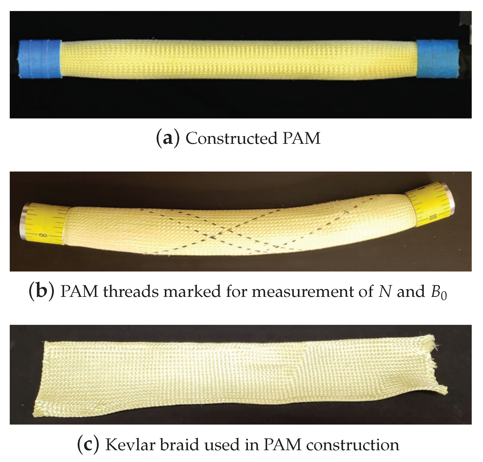
The tested PAM is composed of a latex inner bladder, an aramid braided sleeve, and swaged aluminum end-fittings [29] (Figure 1); it has a diameter of 22.2 mm (7/8 in), and a length of 236 mm (9–9/32 in). The braid is defined by two parameters that are the resting length of each braid thread, , and the number of turns of each thread about the circumference of the PAM, N. For the tested PAM, values for and N were found—through direct measurement of the PAM—to be 251 mm (9.89 in) and 1.09, respectively (Figure 1b). Direct measurement of those two values ensured accuracies within mm (in), and , respectively.

Figure 1.
Tested 22.2 mm diameter PAM.
2.2. Characterization of the PAM’s Actuation
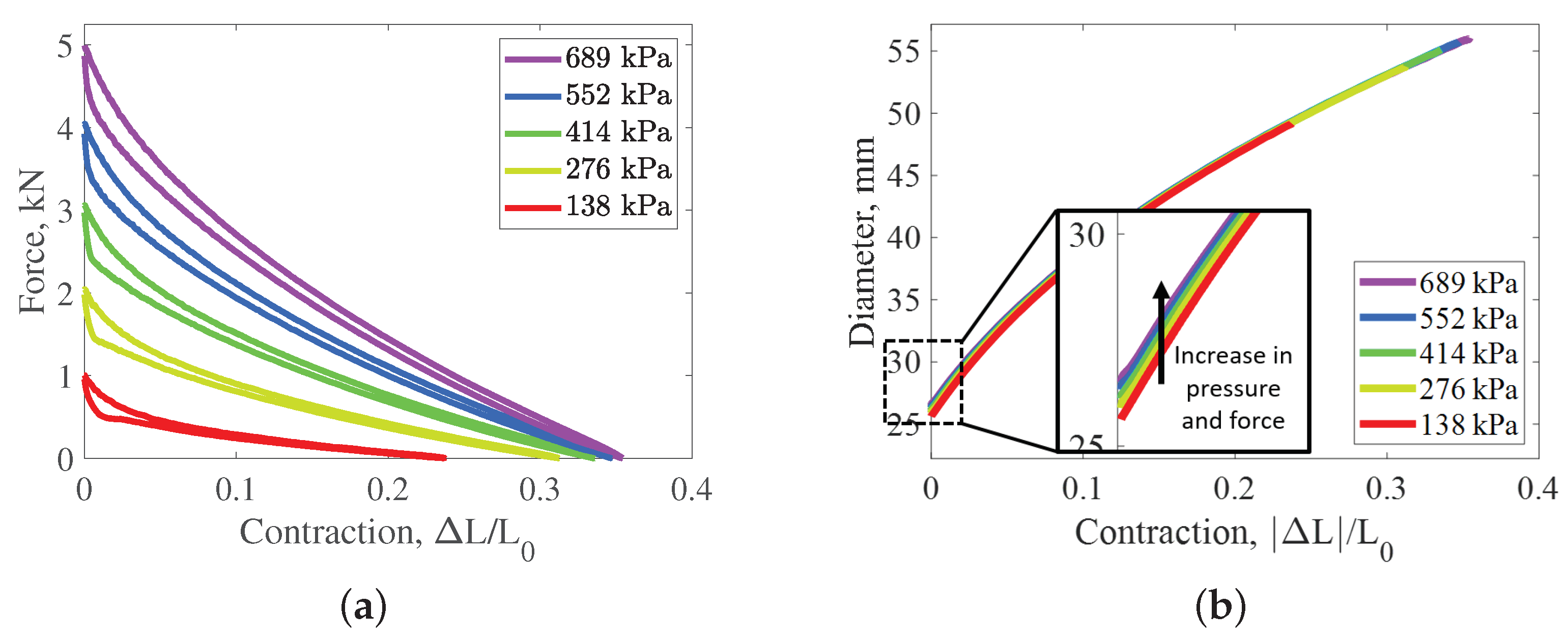
The actuation response of the PAM was characterized using a 98 kN (22 kip) MTS servo-hydraulic test machine (Figure 2a). The MTS machine records the displacement of the cyclic motion, along with the external inputs of force (Honeywell Model 31 Mid) and pressure (Omega PC209-200G5V). This testing was performed by first setting a fixed internal pressure of the PAM, and then cyclically stroking the PAM between its resting length and its pressure-dependent zero force length states. That test sequence was repeated for isobaric pressure tests of 69–689 kPa (10–100 psi) at 69 kPa (10 psi) increments. The pressure of the working fluid was set and maintained at fixed pressures (i.e., isobars) using a previously developed air pressure control system [30]. The PAM was cycled three times at each pressure at a quasi-static rate of 1.0 mm/sec (0.04 in/s). Throughout the testing sequence, measurement data of the PAM’s outer diameter were simultaneously collected at 1 s intervals, by using the photogrammetric acquisition and analysis methods developed in Chambers et al. [29]. Observation of the measurements shows an increase in diameter with increases in pressure which is indicative of what would be expected to occur with stretching of the threads in the braid (Figure 2b).
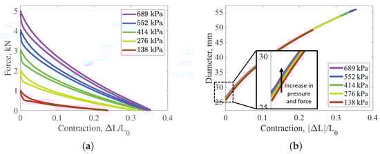
Figure 2.
Characterization testing of the PAM’s actuation and geometry. (a) Actuation Force of PAM with respect to contraction at set isobars; (b) Average diameter of PAM with respect to contraction.
2.3. Characterization of the PAM’s Braid
The braid and its material properties are of particular interest in this research. The braid characterized in this research is composed of 144 Kevlar-49 threads woven into a double-helical tubular sleeve (Figure 1c). The Kevlar-49 thread is cited as having an elastic modulus of GPa (psi), a breaking strength of 254 N (59.3 lbf), and an elongation at failure of 2.4% [31]. Each of those threads is composed of 768 fibers and each fiber has a diameter of 0.012 mm (0.00047 in), resulting in an overall thread cross-sectional area of 0.0858 mm ( in).
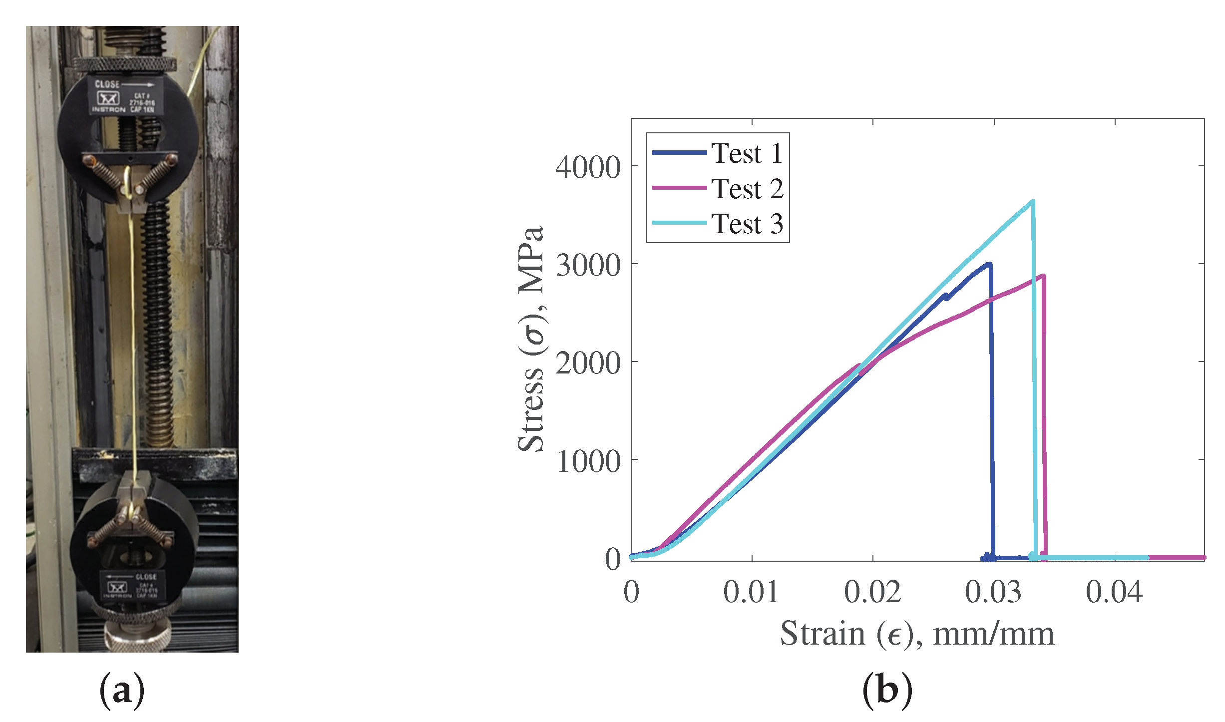
The material specifications of the Kevlar-49 thread were experimentally validated by conducting a tensile failure test on thread samples obtained from the same braid that was used on the PAM. This provides a more complete picture of the stiffness profile of the Kevlar threads but also ensures that the braid’s material properties did not change due to any variation in manufacturing or storage (e.g., degradation due to UV light exposure). Tensile testing of the thread was performed on an Instron 8841 servo-hydraulic testing machine (Figure 3a). Three thread samples of about 10 cm length were prepared by using epoxy to attach tabs for clamping at each end of the thread. Those thread samples were then stretched at a rate of 0.1 mm/s (0.004 in/s) until failure.

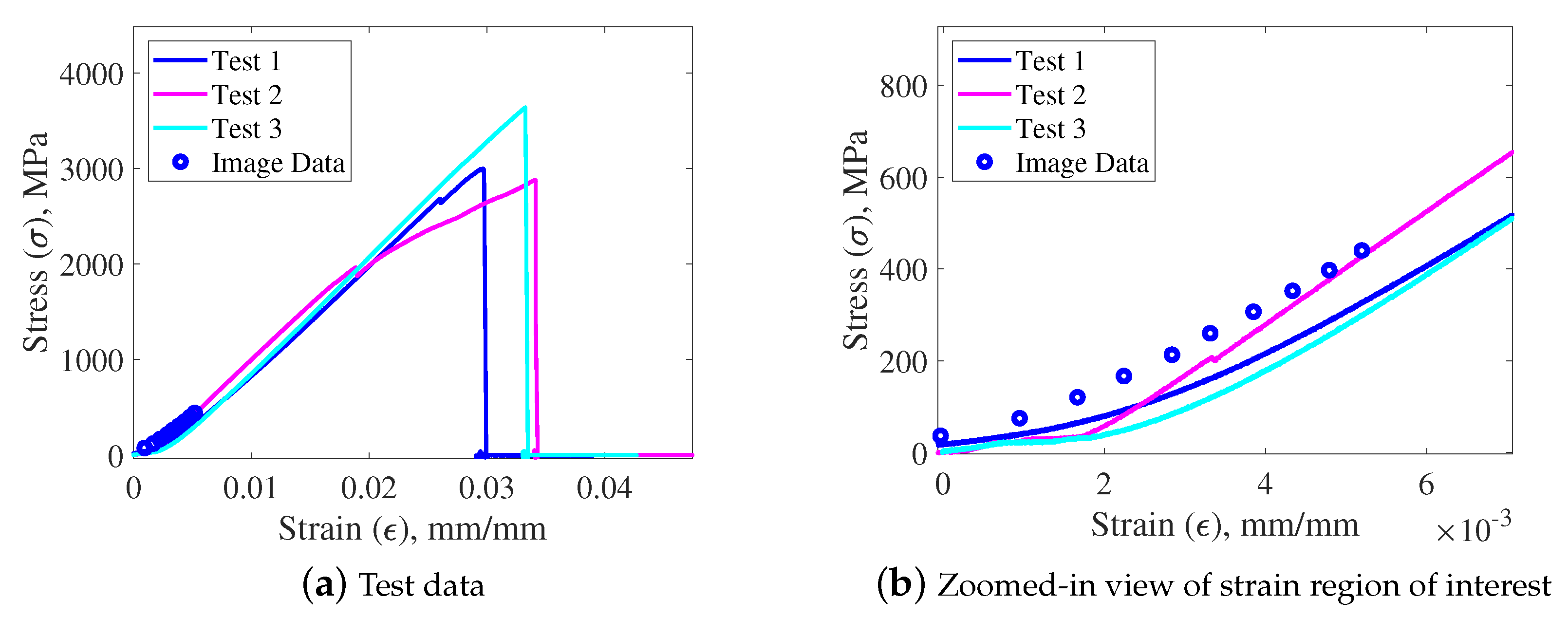
Figure 3.
Testing of Kevlar-49 thread samples. (a) Thread tested on Instron machine; (b) Stress-strain relationships of three tested thread samples.
Test results for three threads are shown in Figure 3b. The experimental modulus of elasticity was approximated by identifying the slope of the linear portion of each curve. The average elasticity for the three samples was found to be GPa (psi) which is within of the cited value for Kevlar-49. Prior to the linear elastic region of each curve, there is a notable nonlinear region that begins at the onset of loading the thread. This nonlinear portion of each curve—which is typically left out of material property reference charts [32]—is due to the initial straightening and uncrimping of the thread fibers, and it continues until all of the fibers in the thread are tensioned and aligned with the thread axis [33]. Note that subsequent analysis of the strain in the braid will find this region of the stress–strain curve to be significant.
3. Analysis of Braid Elasticity Using Measurements of PAM
Characterization data of the PAM’s actuation force and diameter is used for in situ analysis of the braid’s elasticity during the actuation of the PAM. The actuation force data is used to estimate the tension in the braid; diameter measurements of the PAM—obtained using photogrammetry—are used to estimate the stretch in the braid.
Typical methods of obtaining braid dimension and tension estimates rely on models that use a cylindrical approximation of PAM geometry. This approximation is commonly made despite the PAM’s increasingly noncylindrical shape in contracted length states. To ensure the accuracy of our initial investigation of braid tension and stretch, we will focus on the PAM in its resting length state where the cylindrical approximation of the geometry is most accurate.
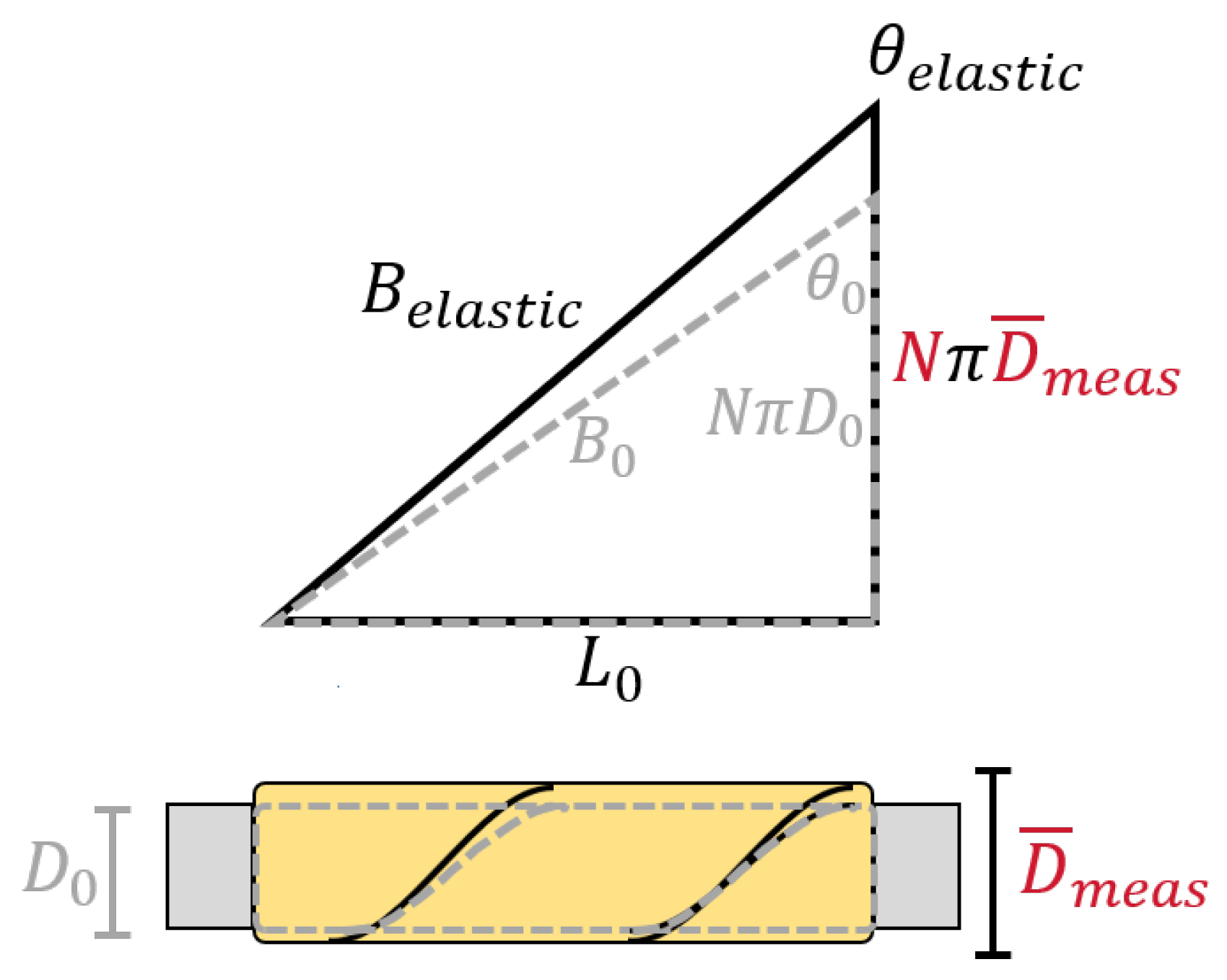
The cylindrical approximation enables a description of the PAM’s geometry for all contraction states of a PAM through the use of a defined triangle relationship (Figure 4). This relationship relates the PAM’s length, L, and diameter, D, with variables that describe the braid including the braid angle, , the length of each braid thread, B, and the number of turns of each thread about the PAM’s circumference, N. With the values of either N or D, and any two of the other dimension variables, the geometry of the PAM can be fully defined using the triangle relationship. For this work, we have known values for N, and of average diameter D for each length state L, thus enabling B and to be estimated for respective states of contraction. Figure 4 shows that an increase in at a fixed-length state of L would result in a stretched length of the braid threads , and a respective change in the braid angle to . The stretched thread length can be estimated using the following equation:
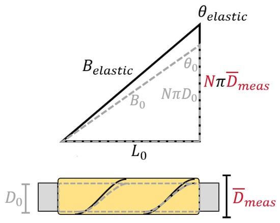
Figure 4.
Triangle relationship of PAM dimensions, and subsequent effect with consideration of braid elasticity.
Estimation of the tension in each thread is based on force equilibrium equations which account for pressure, bladder, and braid forces, and assumes PAMs have a cylindrical geometry [8,10,17]. Force-balance equations for equilibrium in the PAM’s longitudinal (z) and circumferential (c) directions are:
Manipulation of Equation (3) results in the following equation for the thread tension :
where is the number of threads in the braid (), P is the internal pressure of the PAM, and is the actuation force. The last term accounts for the portion of the longitudinal force of the PAM that is due to strain in the bladder; it is a function of the longitudinal stress , bladder volume , and the instantaneous length L.
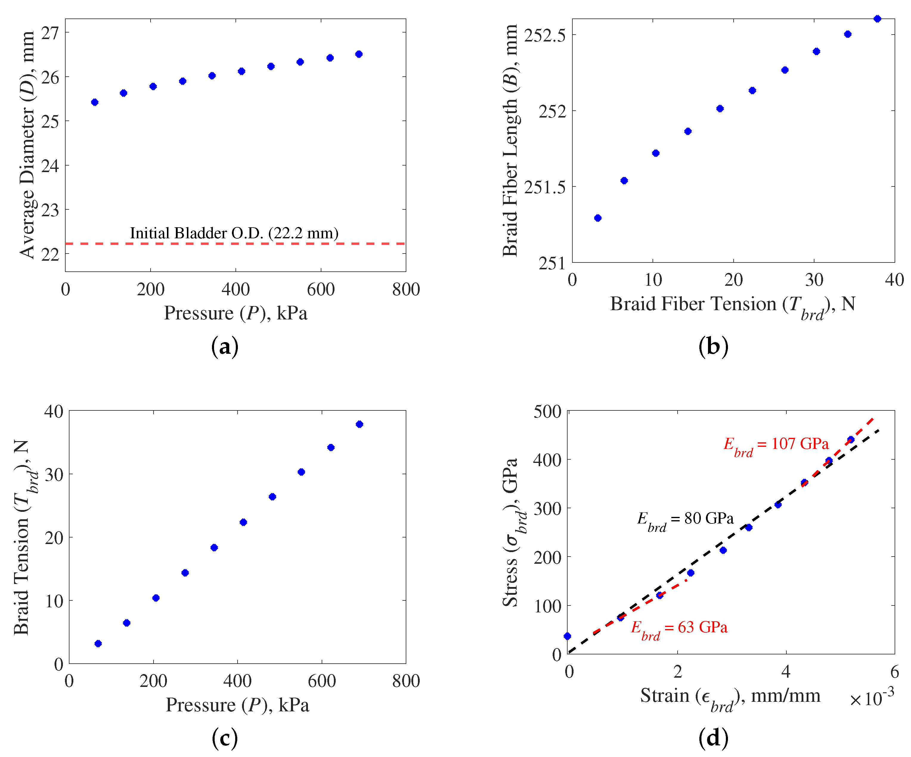
Braid stretch and tension are initially investigated in the resting length state where estimates acquired from Equations (1) and (4)—which are based on the cylindrical approximation—are most accurate. Figure 2b showed a slight increase in diameter with pressure in the resting length state. In this state, the average diameter of the PAM increased by 1.1 mm with an increase in pressure from 0 to 689 kPa (Figure 2b). This increase in diameter creates changes in thread length and braid angle, as seen in Table 1. The nominally linear increase in diameter with pressure supports the hypothesis that the increase in diameter is likely due to braid elasticity. There is a notable initial jump in diameter from the 22.2 mm resting diameter of the bladder which indicates some initial tensioning and realignment of the braid upon pressurization of the PAM. The fiber length at each pressure is estimated by inserting the average diameter values at resting length into Equation (1). This results in a calculated braid stretch of up to 1.3 mm (0.5% stretch) (Figure 5b).

Table 1.
Geometric dimensions calculated for the PAM in the resting length state.
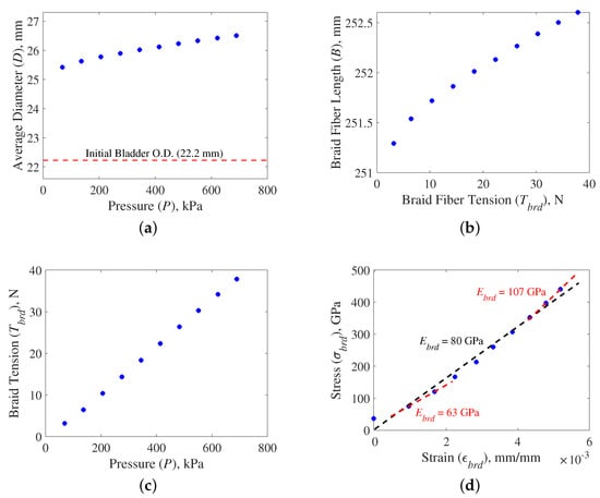
Figure 5.
Analysis of the braid threads through in situ analysis for all tested pressures. (a) Measured average diameter, ; (b) Estimated length of braid threads, ; (c) Estimated tension in braid threads, ; (d) Estimated stress, , and strain, , with linear fit analysis.
The tension in the braid threads is estimated using Equation (4). Because we are only investigating the resting length state, the form of Equation (4) can be simplified to eliminate the last term of the equation by considering that is negligible when the bladder is in the resting length state. The tension in each thread of the braid linearly increases with pressure (Figure 5c). The maximum force of 38 N (8.5 lbf) for each thread is well below the cited failure strength of 264 N (59.3 lbf) for the Kevlar-49 threads.
With the thread stretch and tension estimates, the stress (Equation (5)) and strain (Equation (6)) of the braid thread is then calculated to obtain a measure of braid elasticity while on the PAM (Equation (7)). The equations for stress and strain are as follows:
These stress and strain equations are then used to calculate the braid’s stiffness as follows:
The resulting stress–strain values of the tested PAM produce a nominally linear stress–strain relationship (Figure 5d). A linear fit of the data results in an estimated modulus of GPa ( psi) which is 29% less than the cited value of GPa (psi). A closer inspection of the stress–strain trend reveals a slight nonlinearity in the results. Separate linear fits performed on the low pressure and high-pressure data points found that the high-pressure fit value of GPa (psi) is significantly closer (within 5%) of the cited value.
Analysis of Measured Elasticity Values
The elasticity found through the in situ measurements of the PAM (Figure 3d) is compared to the elasticity found from the tensile characterization testing of the Kevlar thread (Figure 5d), for agreement in Figure 6. In both cases, the tested braid material should result in the same stiffness value.
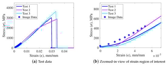
Figure 6.
Each figure compares the stress–strain relationship calculated from (1) tensile test measurements of the Kevlar threads, and (2) estimates from the in situ measurements of the PAM’s braid.
The stress values from the measurement of the PAM appear to be very close to those found in the tensile characterization testing (Figure 6a). The maximum braid strain observed on the PAM is which places it in the low-strain nonlinear region of the tensile test data. This coincides with the nonlinearity observed in the stress–strain relationship found from measurements of the PAM. A comparison of the two sets of data shows that the values are very close in magnitude and have the same basic curvature (Figure 6b). Comparing the stress from the PAM measurements against the average curve of the three tensile tests results in an RMSE for the estimates from the PAM measurements of 26.66 MPa (3867 psi). The slight discrepancy between the measurements of the PAM and the tensile test entails the possibility of a slight overestimation of the tensile loads of the threads on the PAM by 2.54–8.54 N (0.57–1.92 lbf). This is much lower than the 6.58–20.01 N (1.48–4.50 lbf) overestimation of the tensile loads that would be assumed by using the cited linear elastic modulus for the recorded range of strain values.
Overall, a comparison of the elasticity values found from in situ measurements of the PAM, and from tensile testing of individual Kevlar-49 threads, confirms that the source of the fixed-length radial expansion with increases in pressure is, in fact, due to stretching of the braid’s threads. The elasticity of the braid observed on the PAM matched closely with what was expected from both cited and tested values. With the elasticity of the braid now fully characterized, the effects of the braid’s elasticity on geometry and actuation force can be investigated.
4. The Effect of Braid Elasticity on Geometry and Actuation Force
With the stiffness of the braid characterized, the effects of elasticity on the parameters that define PAM geometry (D, , and B) and actuation force can now be analyzed. This analysis is performed by first estimating the stretch of the braid threads for all pressure-contraction states, and then using the triangle relationship, as shown in Figure 4, to calculate the corrected values of B, , and D which now take braid elasticity into account. The effect of the corrected dimensions on the actuation force is then calculated using the Gaylord force equation (Equation (12)).
The traditional approach to estimating the dimensions and actuation force of the PAM has relied on the inelastic braid assumption (i.e., a fixed value for B) and a fixed value of N while assuming a cylindrical geometry for all states of contraction. Using the triangle approximation (Figure 4), values of D and are approximated for all length states L of the PAM, using the following basic relations:
With this work, we are considering braid elasticity effects which result in a value of B that is no longer fixed. The stretched length of each thread is found through the following equation:
where is calculated using Equation (4); once again, the last term is excluded due to a negligible value of . For this form of the equation, the interdependence between the braid’s geometry and tension (and relative stretch) requires an approximation of R and based on either the rigid braid assumption or experimental data. To avoid this assumption, R can be removed as a variable of Equation (10) by insertion of Equation (8) (where ). What remains is a nontrivial solution that requires numerical methods to solve for :
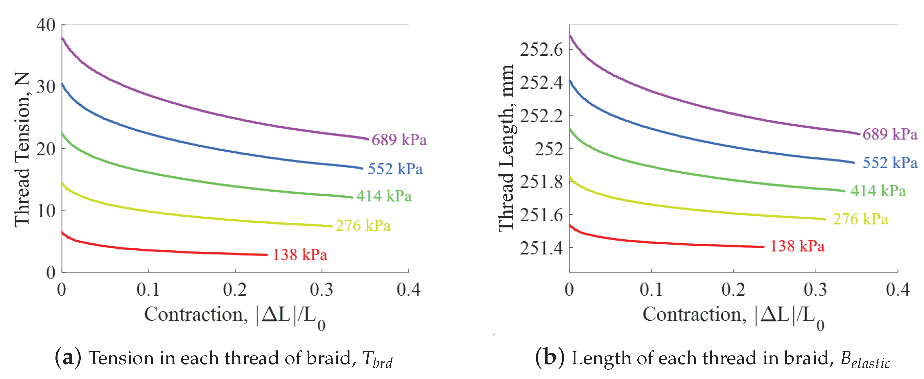
For this equation, can be an input from experimental data, or estimated using the Gaylord force equation (Equation (12)). In our test case, the elastic modulus of the braid, , is assumed to be GPa which is the value found by performing a linear fit of the stress–strain data obtained from the measurement of the PAM (Figure 5d). Now with values of , the braid thread tension and length can then be calculated for all pressure-contraction states of the PAM (Figure 7). The resulting thread tensions and thread lengths in Figure 7 show that:
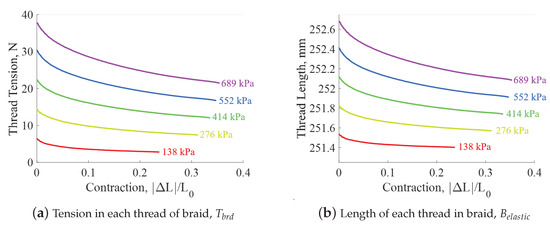
Figure 7.
Thread tension and length with respect to contraction and internal pressure.
- -
- Pressure increases result in increases in braid tension and respective braid stretch
- -
- Maximum stretch occurs in the block force (i.e., resting length) state where the actuation force and respective braid tension is largest
The results show that the maximum braid stretch is 1.5 mm (0.6%) which occurs at 689 kPa.
4.1. Effects of Elasticity with Kevlar-49 Braid
With the stretch of the braid threads now understood for all states of PAM length and pressure, the effect of braid elasticity on its dimensions and actuation force can now be investigated.
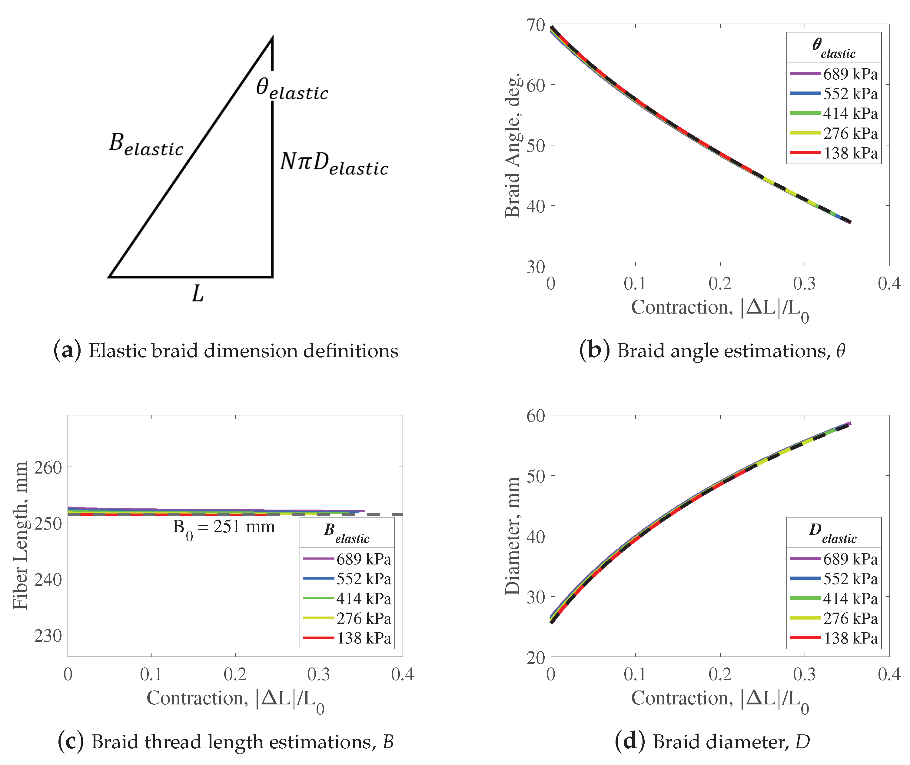
Having known values for , N, L, and (GPa), the dimensions and can be estimated using Equations (8) and (9) (Figure 8a). Figure 8b–d compare the dimensions obtained from assuming the braid is elastic versus inelastic. As with the trends shown for , the effects of braid elasticity are largest in the resting length state and decrease as the PAM contracts. The difference in dimensions between assuming an elastic braid versus an inelastic braid is barely perceptible. The elasticity of the braid resulted in a maximum decrease in braid angle of 0.73 degrees (1.1%), and a maximum increase in diameter of 1.0 mm (3.8%).
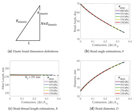
Figure 8.
Estimated braid dimensions for the Kevlar-49 braid (GPa)—comparison between elastic (colored lines) and inelastic (black dashed lines) braid assumptions.
The effect of braid elasticity on actuation force can now be investigated with knowledge of the change in the PAM’s dimensions. The Gaylord force —which approximates the actuation force of the PAM—is used to calculate the expected change in actuation force and is defined as:
where inputs include internal pressure P, and the dimensions R and . The effect of the braid’s elasticity on the Gaylord force is shown in Figure 9. The relatively small change in the PAM’s dimensions with the inclusion of braid elasticity results in a similarly small effect on the actuation force; the inclusion of the effects of braid elasticity resulted in a 28 N (0.6%) decrease in force in the resting length state, and a 13 N (5%) decrease in force in the free contraction state.
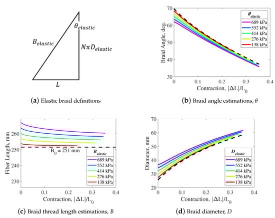
Figure 9.
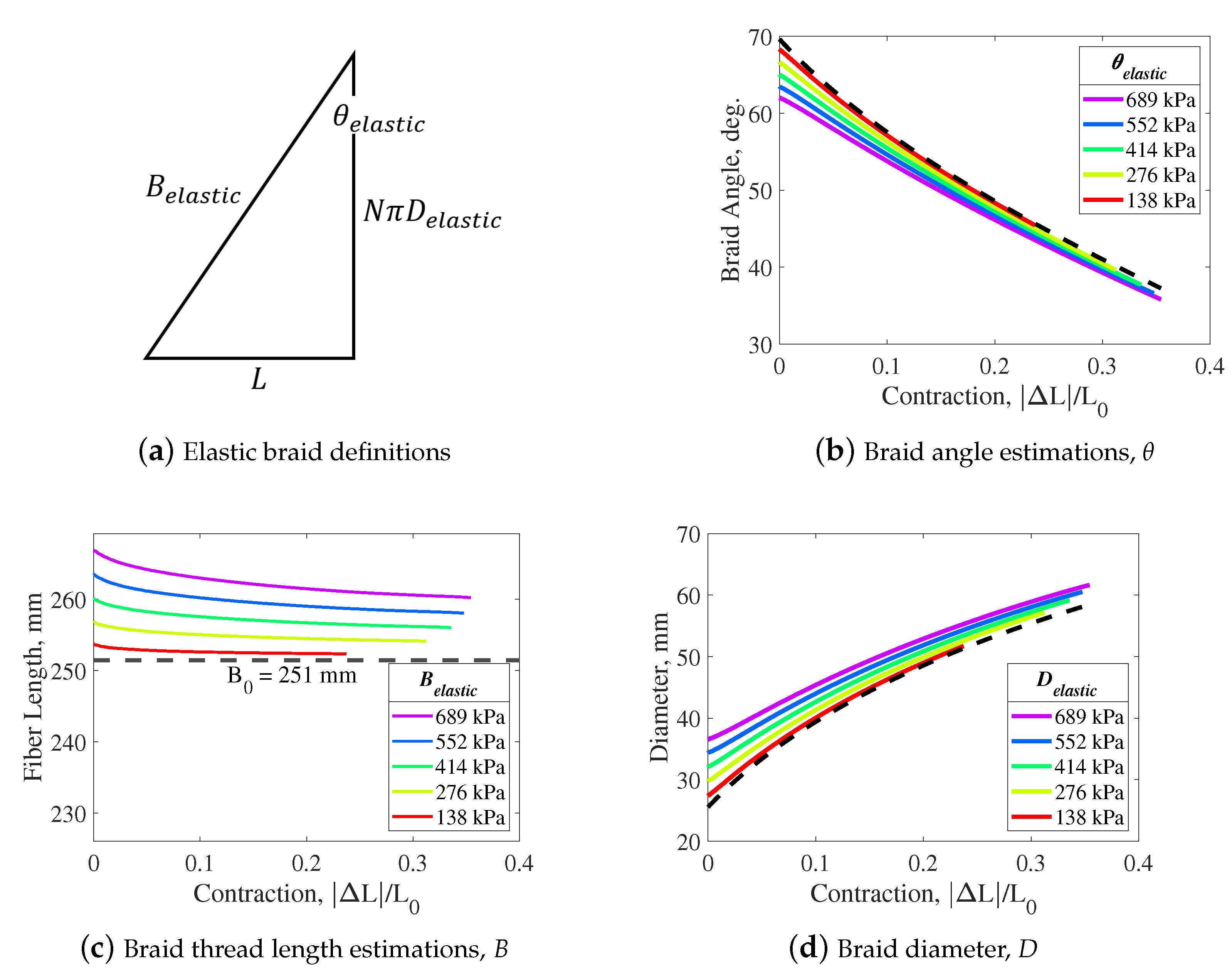
Estimated braid dimensions for a low stiffness braid (GPa)—Comparison between elastic (colored lines) and inelastic (black dashed lines) braid assumptions.
The overall effect of the Kevlar braid’s elasticity is minimal with only small effects on the resulting dimensions and actuation force of the PAM. Therefore, the inelastic braid assumption could be reasonably assumed for basic modeling efforts with this PAM. Future PAM-related research, however, should be careful to not use this conclusion to universally assume that the inelastic braid assumption is sufficient for other PAMs of different constructions. The Kevlar-49 braid used in this work, with a cited modulus of GPa ( psi), has a very high degree of stiffness in comparison to other braid materials that are commonly used such as Nylon (GPa) [34], and polyethylene terephthalate (PET) (GPa) [8].
4.2. Estimated Effects of Lower Stiffness Braid Materials
PAMs commonly use braid materials that have a much lower modulus of elasticity than Kevlar-49 [35]. To investigate the effects of a lower stiffness braid material, a case study is performed. This case study assumes a braid modulus that is 10% of the stiffness of the tested Kevlar-49 (from linear fit of the nonlinear region) (GPa) while maintaining the same actuation forces and initial dimensions of the tested PAM. This assumed modulus value is much closer to that of commonly used materials such as Nylon and PET.
The effect of the braid’s elasticity on the PAM’s dimensions and actuation force is investigated again for comparison (Figure 10b–d). In contrast with the previous results—where a relatively stiff braid was used—the magnitude of stretch estimated for the lower-elasticity material is substantial. The estimated stretch of the braid threads is 15.6 mm (5.8%). This results in a substantial decrease in braid angle of 6.3 degrees (12.3%), and an increase in diameter of up to 11.0 mm (30.1%). These results are comparable to the work of Davis [15], where 5% braid stretch and 33% diameter expansion were observed with a PAM that used a Nylon braid. The similarities between the values observed by Davis and the estimated values in this research support the fidelity of this case study.

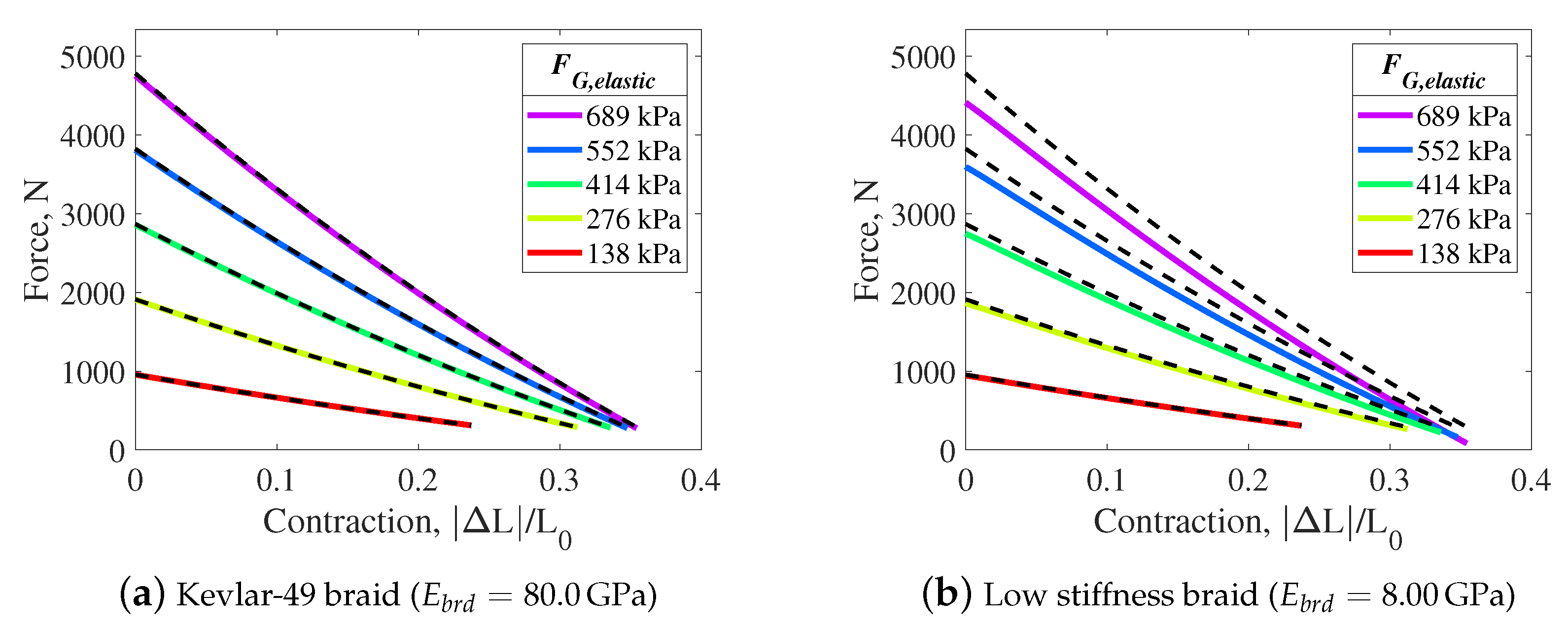
Figure 10.
Gaylord actuation force model estimates for braids of different stiffnesses—comparison between elastic (colored lines) and inelastic (black dashed lines) braid assumptions.
The elasticity of the braid, and respective changes in braid dimensions, result in a substantial decrease in actuation force with the inclusion of braid elasticity effects (Figure 10). When compared to the inelastic braid assumption, the force in the resting length state decreases by up to 370 N (8%) at 689 kPa, while the force at free contraction decreases by up to 210 N (70.4%). Through this example case study, it is evident that the elasticity of the braid can have a substantial effect on the resulting dimensions and actuation force of the PAM.
Table 2 provides further context on the effects of accounting for braid stiffness—in comparison to the inelastic braid assumption—on a PAM’s estimated diameter and actuation force for a range of different braid materials. This table can be used as a reference for future works when considering—based on the braid material used—if the inelastic braid assumption can be reasonably applied for modeling and analysis efforts. In Table 2, six different materials are used to represent the full stiffness range of low- to high-stiffness braid materials. Cited stiffness values for Kevlar-49, PET, and Nylon are used, along with generalized high-, medium-, and low-stiffness braid values; the high-stiffness braid value is based on the experimentally characterized Kevlar-49 braid value (GPa), while the hypothetical medium- and low-stiffness braid materials are 50% and 10%, respectively, of the high-stiffness braid’s value. The table makes clear the relatively small error in using the inelastic braid assumption when relatively stiff braid materials are used, and the relatively large error in using this assumption when relatively soft braid materials are used.
Table 2.
Model differences by assuming the braid is elastic instead of inelastic (at 689 kPa).
5. Conclusions
Prior to this study, the effects of braid elasticity on PAM actuation characteristics were not well studied. As a result, the inelastic braid assumption has been widely used to simplify analysis. A lack of experimental data on the effects of braid elasticity caused this assumption to persist, and its validity must be questioned.
The introduction of a photogrammetric method of measuring PAM dimensions enabled analysis of braid elasticity and its effects on PAM actuation. Photogrammetric measurements showed that the 22.2 mm diameter PAM would expand in diameter in its resting length state by 1.1 mm with an increase in pressure from 0 to 689 kPa. Using the triangle relationship enabled by the cylindrical approximation, this indicated that the Kevlar braid was stretching by up to 0.5%.
Through investigation of braid elasticity using PAM measurements during actuation, the braid was found to operate primarily in the initial nonlinear region of its stress–strain curve. Furthermore, the stress–strain curve developed from the in situ measurements of the PAM was found to closely replicate the nonlinear stress–strain relationship found through tensile testing of individual threads. The linear modulus of elasticity obtained from measurements of the PAM was within 5% of the cited value of Kevlar-49 which aided in assuring the fidelity of the braid elasticity analysis.
The effects of the braid stretch on the resulting dimensions and actuation force of the PAM were quantified. It was found that the Kevlar braid of the tested PAM had an appreciable, but minimal, effect on the dimensions (3.8% maximum increase in diameter) and actuation force (5% maximum decrease). A case study was performed using a modulus of elasticity value similar to that of other commonly used braid materials, and the study found that these less-stiff braid materials would have a significant effect on the dimensions (30.1% maximum increase in diameter) and actuation force (70.4% maximum decrease) of the PAM. The effects of elasticity were especially noticeable in the blocked force state where the actuation force, and resulting tension on the braid threads, is highest in magnitude.
Overall, braid stretch, especially with a lower modulus of elasticity braid materials, can have a substantial effect on the dimensions and actuation force of the PAM. This research demonstrates that the inelastic braid assumption cannot be applied in all situations as has commonly been done in previous work with PAMs. To ensure accurate analyses, the material and loading of the braid must both be considered to ensure that the effects of braid elasticity on PAM actuation are accurately represented.
Author Contributions
This work was conducted collaboratively by all authors. This study was conceptualized and designed by J.M.C. and N.M.W.; Actuator fabrication and experimental setup, J.M.C.; Analysis and data interpretation, J.M.C.; Original draft preparation, J.M.C. Revisions preparation, J.M.C. and N.M.W. Supervisions and project administration, N.M.W. All authors have read and agreed to the published version of the manuscript.
Funding
Research support provided by the U.S. Office of Naval Research under a Basic Research Challenge grant, award No. N000141712063, entitled SEA-STAR: Soft Echinoderm-Inspired Appendages for Strong Tactile Amphibious Robots. Any opinion, findings, and conclusions or recommendations expressed herein are those of the authors.
Data Availability Statement
The data that support the findings of this study are available from the corresponding author, N.M.W., upon reasonable request.
Conflicts of Interest
The authors declare no conflict of interest.
Abbreviations
The following abbreviations are used in this manuscript:
| PAM | Pneumatic Artificial Muscle |
| MTS | Material Testing System |
References
- Huber, J.E.; Fleck, N.A.; Ashby, M.F. The selection of mechanical actuators based on performance indices. Proc. R. Soc. Lond. Ser. Math. Phys. Eng. Sci. 1997, 453, 2185–2205. [Google Scholar] [CrossRef]
- Daerden, F.; Lefeber, D. Pneumatic artificial muscles: Actuators for robotics and automation. Eur. J. Mech. Environ. Eng. 2002, 47, 11–21. [Google Scholar]
- Gaylord, R.H. Fluid Actuated Motor System and Stroking Device. U.S. Patent 2,844,126, 22 July 1958. [Google Scholar]
- Peel, L.D.; Mejia, J.; Narvaez, B.; Thompson, K.; Lingala, M. Development of a simple morphing wing using elastomeric composites as skins and actuators. J. Mech. Des. 2009, 131, 091003. [Google Scholar] [CrossRef]
- Caldwell, D.G.; Tsagarakis, N.; Medrano-Cerda, G. Bio-mimetic actuators: Polymeric pseudo muscular actuators and pneumatic muscle actuators for biological emulation. Mechatronics 2000, 10, 499–530. [Google Scholar] [CrossRef]
- Chambers, J.M.; Carignan, C.R.; Wereley, N.M. Powering a lower limb exoskeleton using pneumatic artificial muscles. In Proceedings of the ASME International Mechanical Engineering Congress and Exposition. American Society of Mechanical Engineers, Columbus, OH, USA, 30 October–3 November 2016; Volume 50534, p. V003T04A051. [Google Scholar]
- Klute, G.K.; Hannaford, B. Accounting for elastic energy storage in McKibben artificial muscle actuators. J. Dyn. Sys. Meas. Control 2000, 122, 386–388. [Google Scholar] [CrossRef] [Green Version]
- Kothera, C.S.; Jangid, M.; Sirohi, J.; Wereley, N.M. Experimental characterization and static modeling of McKibben actuators. J. Mech. Des. 2009, 131, 091010. [Google Scholar] [CrossRef]
- Tondu, B. Modelling of the McKibben artificial muscle: A review. J. Intell. Mater. Syst. Struct. 2012, 23, 225–253. [Google Scholar] [CrossRef]
- Hocking, E.G.; Wereley, N.M. Analysis of nonlinear elastic behavior in miniature pneumatic artificial muscles. Smart Mater. Struct. 2012, 22, 014016. [Google Scholar] [CrossRef]
- Pillsbury, T.E.; Kothera, C.S.; Wereley, N.M. Effect of bladder wall thickness on miniature pneumatic artificial muscle performance. Bioinspir. Biomim. 2015, 10, 055006. [Google Scholar] [CrossRef] [Green Version]
- Solano, B.; Rotinat-Libersa, C. Compact and lightweight hydraulic actuation system for high performance millimeter scale robotic applications: Modeling and experiments. J. Intell. Mater. Syst. Struct. 2011, 22, 1479–1487. [Google Scholar] [CrossRef]
- Robinson, R.M.; Kothera, C.S.; Wereley, N.M. Quasi-static nonlinear response of pneumatic artificial muscles for both agonistic and antagonistic actuation modes. J. Intell. Mater. Syst. Struct. 2015, 26, 796–809. [Google Scholar] [CrossRef]
- Meller, M.A.; Bryant, M.; Garcia, E. Reconsidering the McKibben muscle: Energetics, operating fluid, and bladder material. J. Intell. Mater. Syst. Struct. 2014, 25, 2276–2293. [Google Scholar] [CrossRef]
- Davis, S.; Tsagarakis, N.; Canderle, J.; Caldwell, D.G. Enhanced modelling and performance in braided pneumatic muscle actuators. Int. J. Robot. Res. 2003, 22, 213–227. [Google Scholar] [CrossRef]
- Colbrunn, R.W.; Nelson, G.M.; Quinn, R.D. Modeling of braided pneumatic actuators for robotic control. In Proceedings of the 2001 IEEE/RSJ International Conference on Intelligent Robots and Systems, Expanding the Societal Role of Robotics in the the Next Millennium (Cat. No. 01CH37180), Maui, HI, USA, 29 October 2001–3 November 2001; Volume 4, pp. 1964–1970. [Google Scholar]
- Carlo Ferraresi, W.F.; Walter Franco, W.; Bertetto, A. Flexible pneumatic actuators: A comparison between the McKibben and the straight fibres muscles. J. Rob. Mechatron. 2001, 13, 56–63. [Google Scholar] [CrossRef]
- Tondu, B.; Lopez, P. Modeling and control of McKibben artificial muscle robot actuators. IEEE Control Syst. Mag. 2000, 20, 15–38. [Google Scholar]
- Chou, C.P.; Hannaford, B. Measurement and modeling of McKibben pneumatic artificial muscles. IEEE Trans. Robot. Autom. 1996, 12, 90–102. [Google Scholar] [CrossRef] [Green Version]
- Schulte, H.F. Characteristics of the Braided Fluid Actuator; Schulte, H.F., Jr., Adamski, D.F., Pearson, J.R., Eds.; Technical Report; Office of Vocational Rehabilitation, Department of Health, Education, and Welfare: Washington, DC, USA, 1961.
- Wang, G.; Wereley, N.M.; Pillsbury, T. Non-linear quasi-static model of pneumatic artificial muscle actuators. J. Intell. Mater. Syst. Struct. 2015, 26, 541–553. [Google Scholar] [CrossRef]
- Tiwari, R.; Meller, M.A.; Wajcs, K.B.; Moses, C.; Reveles, I.; Garcia, E. Hydraulic artificial muscles. J. Intell. Mater. Syst. Struct. 2012, 23, 301–312. [Google Scholar] [CrossRef]
- De Volder, M.; Reynaerts, D. Pneumatic and hydraulic microactuators: A review. J. Micromech. Microeng. 2010, 20, 043001. [Google Scholar] [CrossRef] [Green Version]
- Davis, S.; Caldwell, D.G. Braid effects on contractile range and friction modeling in pneumatic muscle actuators. Int. J. Robot. Res. 2006, 25, 359–369. [Google Scholar] [CrossRef]
- Tsagarakis, N.; Caldwell, D.G. Improved modelling and assessment of pneumatic muscle actuators. In Proceedings of the 2000 ICRA. Millennium Conference, International Conference on Robotics and Automation. Symposia Proceedings (Cat. No. 00CH37065), San Francisco, CA, USA, 24–28 April 2000; Volume 4, pp. 3641–3646. [Google Scholar]
- Tondu, B.; Lopez, P. The McKibben muscle and its use in actuating robot-arms showing similarities with human arm behaviour. Ind. Robot. Int. J. 1997, 24, 432–439. [Google Scholar] [CrossRef]
- Chou, C.P.; Hannaford, B. Static and dynamic characteristics of McKibben pneumatic artificial muscles. In Proceedings of the 1994 IEEE International Conference on Robotics and Automation, San Diego, CA, USA, 8–13 May 1994; pp. 281–286. [Google Scholar]
- Doumit, M.; Fahim, A.; Munro, M. Analytical modeling and experimental validation of the braided pneumatic muscle. IEEE Trans. Robot. 2009, 25, 1282–1291. [Google Scholar] [CrossRef]
- Chambers, J.M.; Wereley, N.M. Photogrammetric measurement and analysis of the shape profile of pneumatic artificial muscles. MDPI Actuators 2021, 10, 72. [Google Scholar] [CrossRef]
- Chambers, J.M.; Wereley, N.M. Influence of hydraulic versus pneumatic working fluids on quasi-static force response of fluidic artificial muscles. J. Intell. Mater. Syst. Struct. 2021, 32, 385–396. [Google Scholar] [CrossRef]
- DuPont Advanced Fiber Systems. Kevlar Aramid Fiber Technical Guide; Technical Report; DuPont: Richmond, VA, USA, 2017. [Google Scholar]
- ASTM D3822/D3822M-14(2020); Standard Test Method for Tensile Properties of Single Textile Fibers. American Society for Testing and Materials: West Conshohocken, PA, USA, 2000.
- Tapie, E.; Shim, V.; Guo, Y. Influence of weaving on the mechanical response of aramid yarns subjected to high-speed loading. Int. J. Impact Eng. 2015, 80, 1–12. [Google Scholar] [CrossRef]
- Mark, J.E. (Ed.) Polymer Data Handbook; Oxford University Press: Oxford, UK, 2009. [Google Scholar]
- Raja, S.N.; Basu, S.; Limaye, A.M.; Anderson, T.J.; Hyland, C.M.; Lin, L.; Alivisatos, A.P.; Ritchie, R.O. Strain-dependent dynamic mechanical properties of Kevlar to failure: Structural correlations and comparisons to other polymers. Mater. Today Commun. 2015, 2, e33–e37. [Google Scholar] [CrossRef] [Green Version]
Publisher’s Note: MDPI stays neutral with regard to jurisdictional claims in published maps and institutional affiliations. |
© 2022 by the authors. Licensee MDPI, Basel, Switzerland. This article is an open access article distributed under the terms and conditions of the Creative Commons Attribution (CC BY) license (https://creativecommons.org/licenses/by/4.0/).