Article

Resonant Adaptive MEMS Mirror

1
Mechanical and Mechatronics Engineering, University of Waterloo, Waterloo, ON N2L 3G1, Canada
2
Systems Design Engineering, University of Waterloo, Waterloo, ON N2L 3G1, Canada
3
Electrical and Computer Engineering, University of Waterloo, Waterloo, ON N2L 3G1, Canada
*
Author to whom correspondence should be addressed.
Actuators 2022, 11(8), 224; https://doi.org/10.3390/act11080224
Submission received: 20 June 2022 / Revised: 26 July 2022 / Accepted: 4 August 2022 / Published: 5 August 2022
(This article belongs to the Special Issue Micro/Nano Electromechanical Sensors and Actuators)

Abstract

:
A novel MEMS continuous deformable mirror (DM) is presented. The mirror can be integrated into optical systems to compensate for monochromatic and chromatic aberrations. It is comprised of a 1.6 mm circular plate supported by eight evenly spaced flexural springs. Unlike traditional bias actuated DMs, it uses resonant electrostatic actuation (REA) to realize low- and high-order Zernike modes with a single drive signal. Instead of the hundreds or thousands of electrodes deployed by traditional DMs, the proposed DM employs only 49 electrodes and eliminates the need for spatial control algorithms and associated hardware, thereby providing a compact low-cost alternative. It also exploits dynamic amplification to reduce power requirements and increase the stroke by driving the DM at resonance. The DM was fabricated using a commercial silicon-on-insulator (SOI) MEMS process. Experimental modal analysis was carried out using laser Doppler vibrometry (LDV) to identify mode shapes of the DM and their natural frequencies. We are able to observe all of the lowest eight Zernike modes.

1. Introduction

The performance of optical systems is often limited by aberrations that degrade image resolution and contrast. Aberrations may be induced by atmospheric turbulence, temperature variations, optical misalignment, layer inhomogeneity, or shape imperfection [1,2]. Adaptive optics (AO) seeks to improve the performance of those systems by compensating for optical aberrations. Deformable mirrors (DMs) are the most common adaptive correction elements due to their high optical efficiency and independence from wavelength [3]. Recent progress in AO has shown that DMs can be used in many applications including astronomy [4,5], microscopy [1,6,7,8], and ophthalmology [9,10] to correct optical aberrations and improve image resolution.
Zernike polynomials are used to describe wavefront aberrations [11,12]. DMs deform their reflective surfaces to depict a Zernike mode in order to eliminate the corresponding aberration in the incident wavefront [13]. A distributed actuator array underneath the mirror surface provides the actuation necessary to realize the required deformation. The performance of DMs is evaluated in terms of the realized stroke, power consumption, device complexity, and fabrication costs [14,15].
The last 50 years have seen the development of a large number of DMs. Traditional DMs were initially developed to eliminate optical aberrations in telescopes [16]. However, they were bulky, expensive, and their power consumption was high [17,18,19]. The advent of micromachining and microelectromechanical systems (MEMS) presented an alternative to those mirrors and extended the field of AO into microscopy, laser machining, ophthalmoscopy, and optical coherence tomography [15,20]. MEMS technology enabled the manufacturing of low-cost, low-power-consumption, and compact DMs [3,21]. They are made of either discrete segments [22,23,24,25,26] or a single continuous plate [15,27,28,29]. Piezoelectric, electrostatic, electrothermal, and electromagnetic actuation mechanisms are used in MEMS DMs with the majority relying on either electrostatic or piezoelectric actuation.
Electrostatic actuation [15,22,23,24,27,28,29,30,31] is more popular than others due to its compatibility with microfabrication, simple structure, and fast response time [32,33]. However, it requires high operation voltages and a large number of actuators, which poses complex hardware and control challenges [34,35,36,37,38]. Specifically, DC actuators have “influence functions” that describe the amount of deformation that they create in the reflective surface [13,39]. Deforming the DM into a given Zernike mode requires the solution of a linear system consisting of those functions to find the magnitude of the voltage each of them requires [14]. A complex control system, complicated circuit, and associated hardware are then necessary to supply voltage individually to each of them. More complex, higher-order Zernike modes require the recruitment of larger numbers of actuators. For example, Boston Micromachines Inc.’s DMs [15,24,27] can precisely compensate for low and high order aberrations, but they rely on a large number of electrodes, complex algorithms, and associated hardware.
Piezoelectric actuation [40,41,42,43] can provide large stroke with low voltages, but piezoelectric actuator structures are complicated and suffer from hysteresis and incompatibility to micromachining. Electromagnetic actuation [44,45] produces the largest stroke compare to others. However, it requires provisioning the DM with a coil and permanent magnets. Electrothermal actuation [46,47,48] can generate high forces to reach large stroke, but it suffers from high power consumption and a long response time.
Recent developments in AO have emphasized the need for miniaturized, large-stroke, low-cost, and easy-to-drive DMs to compensate for optical aberrations in real time [39,49,50]. In this paper, we present a novel MEMS DM that can be used to correct wavefront aberrations during real-time scanning. It employs resonant electrostatic actuation (REA) via 49 electrodes to deform a circular plate. REA drives the mirror at resonance and exploits dynamic amplification to increase the stroke with a minimal number of electrodes. The DM surface is continuous, thereby eliminating light diffraction across the facesheet. It can correct both low- and high-order aberrations using a single actuator array driven by a single voltage waveform.
The DM is designed to meet ophthalmology needs and fabricated using a silicon-on-insulator (SOI) MEMS fabrication process [51]. Its natural frequencies and mode shapes are predicted by finite element (FEM) simulations and experimentally verified using laser Doppler vibrometry (LDV). The evolution of the mirror surface at the resonance of the first axisymmetric mode (defocus mode) is measured and compared with the theoretical Zernike defocus mode.

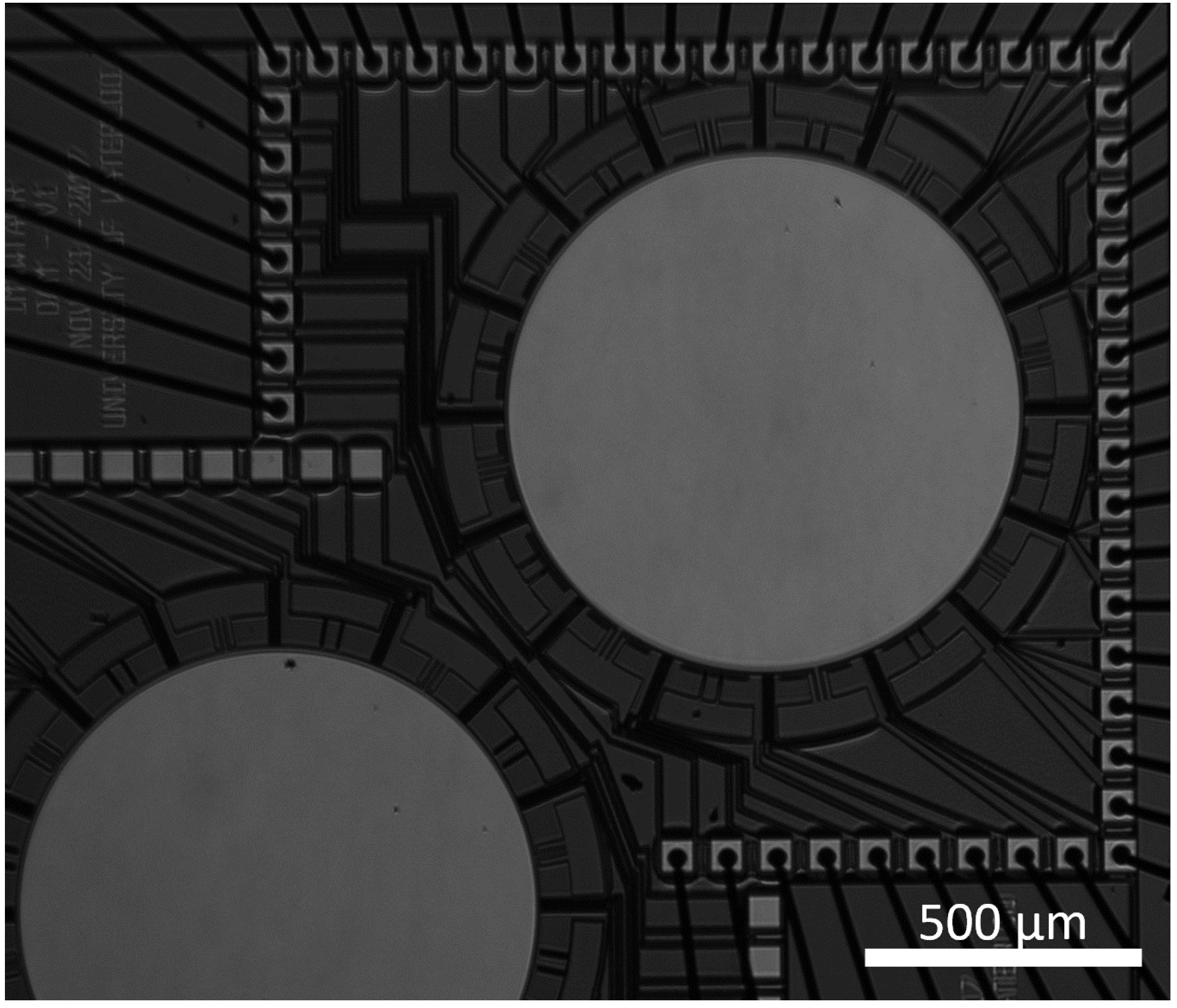
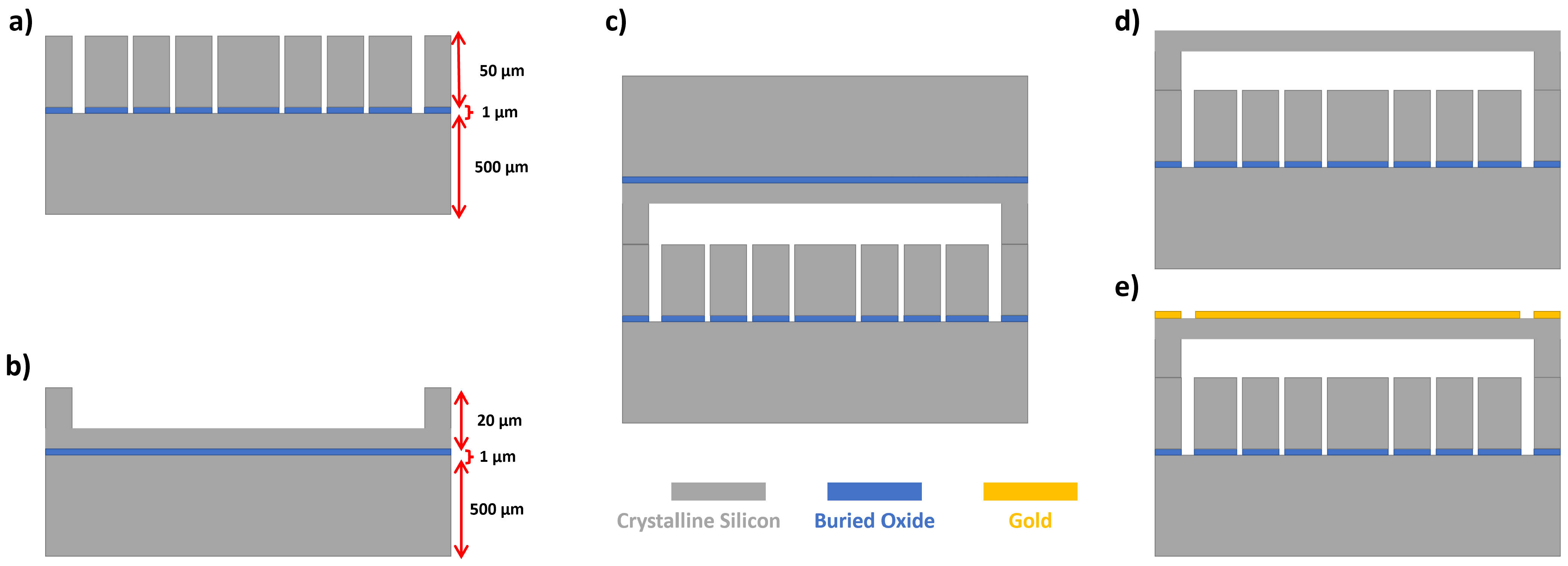
2. Mirror Design and Fabrication

2.1. Design

The DM, shown in Figure 1, is comprised of 10 µm thick circular crystal silicon plate with a diameter of 1.6 mm. A 75 nm thick gold layer is deposited on top of it to create a reflective surface. The plate is supported by eight equally spaced 100 µm long, 15 µm wide, and 10 µm thick beams. The DM is actuated electrostatically via 49 electrodes arranged into four concentric tiers. The air gap between the bottom surface of the plate and the electrodes is 20 µm. The dimensions of the DM are listed in Table 1 and illustrated in Figure 2.
In ophthalmology, fifth order Zernike modes are used to categorize the aberrations induced by the human eye. These aberrations in turn degrade the image resolution of the retina during laser scanning. Therefore, the first design criterion of the proposed DM is to replicate those biologically relevant Zernike modes. FEA found that supporting the circular plate with two to seven evenly spaced beams is not enough to replicate those modes.
Eight identical beams were found to be the minimum number necessary to replicate the desired Zernike modes. It was also found that increasing the support beams stiffness can distort the plate modes away from the Zernike modes. Therefore, COMSOL simulations were carried out to minimize the impact of the support beams on the plate mode shapes. We found that the support beams’ stiffness was low enough to minimize their interference with the plate modes when their dimensions were as follows: length l = 100 µm, width w = 15 µm, and thickness t = 10 µm.
Figure 1. A microscopic picture of the DM.
Actuators 11 00224 g001
Table 1. Dimensions of the DM.
Parameterμm
Mirror radius, a 800
Mirror thickness, t10
Beam length, l100
Beam thickness, h10
Beam width, w15
Capacitive gap, d20
Figure 2. A schematic of the DM and its dimensions.
Actuators 11 00224 g002
The DM operating principle calls for dynamic actuation at the natural frequency of the DM corresponding to the desired Zernike mode. This approach exploits dynamic amplification to guarantee maximum stroke. The third design criterion calls for the operating (natural) frequencies above the f i > 10 kHz, to protect against shot noise and external disturbances, and below f i < 1 MHz to reduce the complexity of the drive circuit. These design criteria along with the limitations of Micragem-Si fabrication process [51] set the mirror plate diameter and thickness.
The fabrication process uses two SOI wafers. The mirror plate and support beams are fabricated the device layer of the top wafer, made of crystalline silicon (100) with a modulus elasticity of E = 129.5 GPa, a density of ρ = 2320 kg/m 3 , and a Poisson’s ratio of v = 0.28 . The electrodes and mirror anchors are patterned into the device layer of the bottom wafer. The two wafers are anodically bonded to form the DM and a 75 nm gold layer is deposited on top of it to create the mirror reflective surface. Figure 3 shows the fabrication steps.

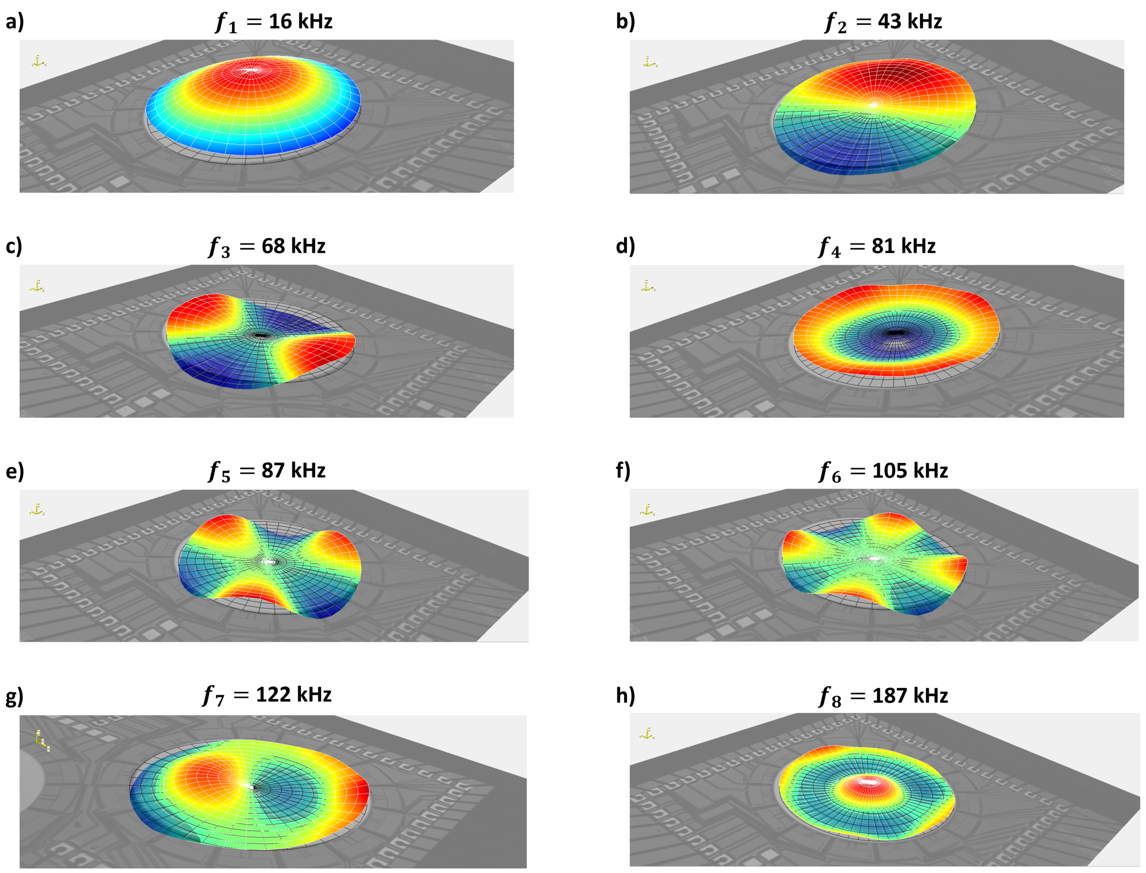
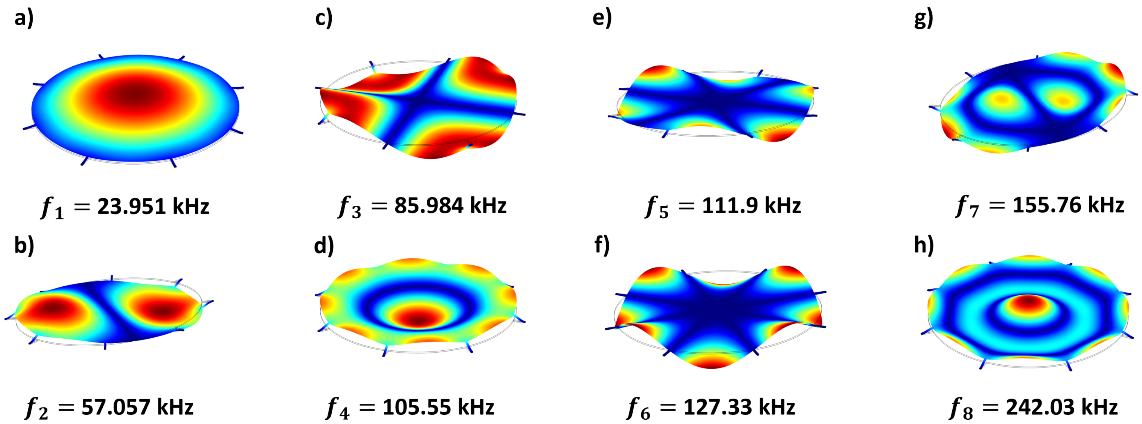
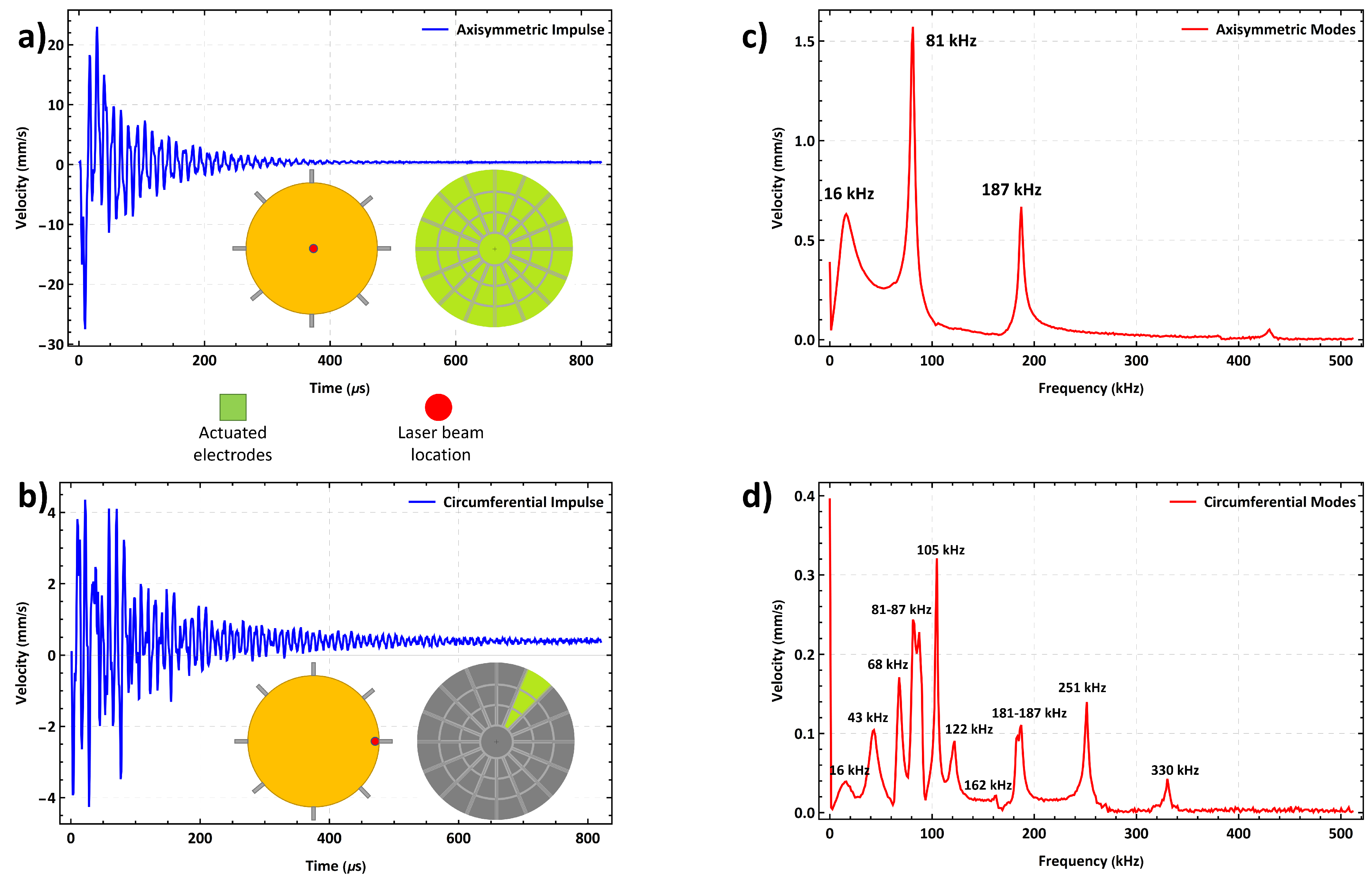
2.2. Predicted Mode Shapes

An eigenfrequency analysis was conducted by using FEA package COMSOL Multiphysics to obtain the DM mode shapes and their natural frequencies. The results show that the defocus mode (1,0), primary coma mode (1,1), astigmatism mode (0,2), primary spherical mode (2,0), trefoil mode (0,3), secondary coma mode (2,1), tetrafoil mode (0,4), and secondary spherical mode (3,0) appear at frequencies of f 1 = 23.951 kHz, f 2 = 57.07 kHz, f 3 = 85.984 kHz, f 4 = 105.55 kHz, f 5 = 111.9 kHz, f 6 = 127.33 kHz, f 7 = 155.76 kHz, and f 8 = 242.03 kHz, respectively. The mode shapes are shown in Figure 4. Note that the colour map for the mode shapes is defined in terms of absolute displacement values. As a result, the locations of maximum and minimum displacements within a mode shape are coloured in red. Aberrations in the DM modes away from Zernike modes are particularly pronounced in the primary and secondary spherical modes. They occur due to the presence and stiffness of the support beams.

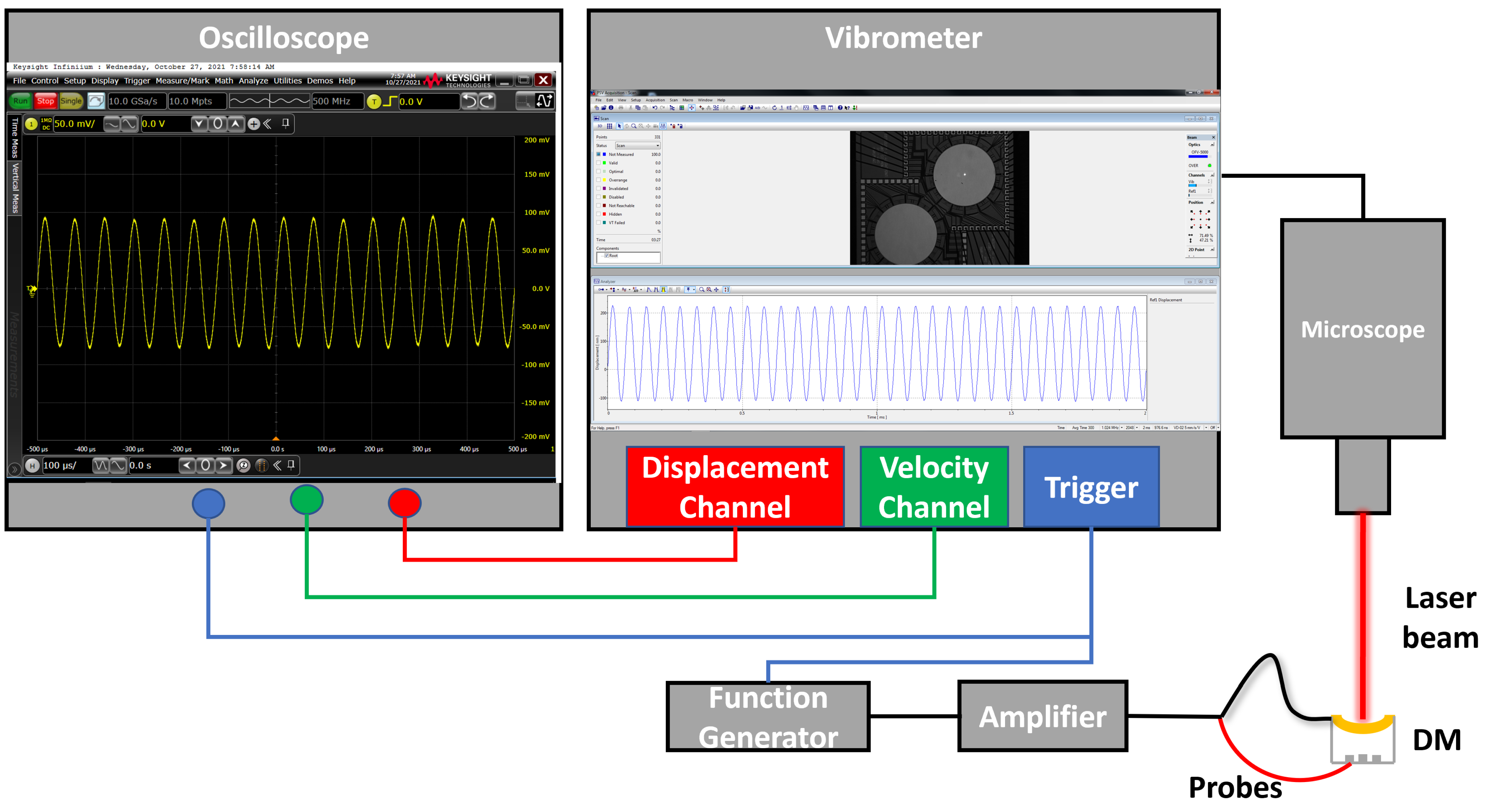
3. Experimental Characterization

Modal analysis was carried out experimentally using LDV. Figure 5 shows a schematic of the experimental setup. A function generator and a voltage amplifier provided the excitation signal. LDV was used to capture out-of-plane displacement and velocity of the target point on the mirror surface. The output signals were discretized using an oscilloscope.
The axisymmetric and circumferential modes were excited by applying an electrostatic forcing pulse train to an axisymmetric and a circumferential actuator arrays, respectively. The spatial distribution of the actuator arrays are highlighted in green in the insets of Figure 6a,b. The voltage waveform in both cases had a frequency of 1 kHz, an amplitude of 75 V, and a pulse width of 20 µs. The response was measured using the vibrometer at the center of the mirror plate and a point on the perimeter for axisymmetric and circumferential modes, respectively, as illustrated in the insets of Figure 6a,b. The time-histories of the velocity response to a single pulse at those points were averaged a 100 times and are shown in Figure 6.
The FFT of the center point velocity, Figure 6c, shows three peaks corresponding to the first three axisymmetric modes, namely defocus (1,0), primary spherical (2,0), and secondary spherical (3,0), with resonant frequencies at f 1 = 16 kHz, f 4 = 81 kHz, and f 8 = 187 kHz, respectively. The FFT of the perimeter point velocity, Figure 6d, shows seven circumferential modes in addition to the three axisymmetric modes described above. Specifically, the peaks at f 2 = 43 kHz, f 3 = 68 kHz, f 5 = 87 kHz, f 6 = 105 kHz, f 7 = 122 kHz, f 9 = 251 kHz, and f 10 = 330 kHz correspond to primary coma (1,1), astigmatism (1,2), trefoil (1,3), tetrafoil (1,4), secondary coma (2,1), pentafoil (1,5), and hexafoil (1,6) Zernike modes, respectively. A mode appearing at 162 kHz was not identified. The tetrafoil (1,4) was also observed at 187 kHz where it was interacting with secondary spherical mode (3,0).

4. Results and Discussion

The DM can correct optical aberrations by taking their counter shape. To achieve that, it is driven by a harmonic excitation force with a frequency tuned to the resonance frequency of the required mode. Recalling that the electrostatic force is given by:
F e = α V 2 ( t ) ( d w ) 2
where α is a parameter dependent on the actuator dimensions, V ( t ) is the driving voltage signal, d is the capacitive gap, and w is the mirror counter deformation. For a harmonic excitation signal
V ( t ) = A cos ( 2 π f t )
the electrostatic force takes the form
F e = α ( d w ) 2 A 2 2 + A 2 2 cos ( 4 π f t )
we note that the signal frequency f is half the forcing frequency and, therefore, resonance excitation requires setting the signal frequency to f = 1 2 f i . Under such an excitation, the DM surface will deform to replicate desired mode shape.
The resonant DM is designed for pulsed laser scanning instead of continuous laser scanning. Therefore, the frequency of the incident pulsed laser beam should be synchronized with the frequency of the mirror oscillations f i . To demonstrate this functionality, axisymmetric and circumferential modes observed above were realized experimentally.
First, the three axisymmetric mode shapes were captured by applying a single harmonic voltage signals with an amplitude of 100 V to the electrodes of the axisymmetric actuation scheme. The signal frequency was set to f = f 1 / 2 , f 4 / 2 , and f 8 / 2 . In each case, the multipoint scan of the LDV was used to capture the resulting mode shape.
The circumferential mode shapes were realized by applying a single harmonic voltage signal with an amplitude of 100 V to the electrodes of the circumferential actuation scheme. The frequency of the signal was set to f = f 2 / 2 , f 3 / 2 , f 5 / 2 , f 6 / 2 , and f 7 / 2 to realize resonant excitation and a LDV multipoint scan was carried out to capture the resulting mode shape. Figure 7 shows the extracted experimental mode shapes.
Comparing the measured mode shapes, Figure 7, to those predicted numerically, Figure 4, we find that they are in qualitative agreement. Furthermore, the order of the modes is preserved between the model and the fabricated DM. However, the measured natural frequencies are uniformly lower than those predicted by the model with the difference varying from 20.9% to 24.5% except for the defocus mode, which is lower by 50%. The uniform drop in natural frequencies suggests that the underlying reason is lower support beam stiffness than that estimated by the FEM model. Inspection of their length and width showed that they matched the design values. The reduced beam stiffness may be a result of support nonideality.
To evaluate the quantitative agreement between the experimental modes and the theoretical Zernike modes, a comparison was carried out for the defocus mode. The harmonic signal of Equation (2) was applied to the axisymmetric excitation scheme with A = 100 V and f = 8 kHz to excite the defocus mode. The evolution of the mirror surface while oscillating in this mode w d ( r , t ) was measured using the LDV at 15 grid-points evenly spaced along a DM diameter starting from the tip of one support beam to the tip of the opposite beam. The mirror dynamic deformation was measured as the relative displacement between the measurement point and the averaged displacement of the beam tips. This corresponds to response of the second term of Equation (3).
A step voltage with a frequency of 1.024 kHz and an amplitude, equal to the root mean square (RMS) of this harmonic excitation signal 70.71 V, was applied to axisymmetric actuation scheme to measure the equilibrium profile around which the mirror surface oscillates w s ( r ) . The LDV was used to measure the steady-state response at the same 15 grid-points. This corresponds to the response of the first term in the Equation (3). The total response was evaluated as
w ( r , t ) = w d ( r , t ) + w s ( r )
A least square fit was deployed to estimate the evolution of the continuous DM surface out of the measured displacements of 15 grid points. The maximum stroke at the mirror center was measured to be 1.2 µm.
Figure 7. Experimental mode shapes obtained by using a laser Doppler vibrometer. (a) Defocus mode at f 1 = 16 kHz. (b) Primary coma at f 2 = 43 kHz. (c) Astigmatism at f 3 = 68 kHz. (d) Primary spherical at f 4 = 81 kHz. (e) Trefoil at f 5 = 87 kHz. (f) Tetrafoil at f 6 = 105 kHz. (g) Secondary coma at f 7 = 122 kHz. (h) Secondary spherical at f 8 = 187 kHz.
Actuators 11 00224 g007
The theoretical Zernike mode (red line) and DM mode (blue line) are compared in Figure 8. The grid points are shown in the figure as green dots. The radial location is normalized with respect to the DM diameter and the displacement is normalized with respect to the stroke. The RMS error (deviation) of the DM mode from the Zernike mode was found to be less than 0.32 over the mirror plate and less than 0.05 over a 1.1 mm diameter circle at the center of the mirror.
Table 2 compares the design and performance of the resonant DM to other state-of-the-art MEMS DMs. While piezoelectrically, electromagnetically, and electrothermally actuated DMs exist, the dominant actuation method is electrostatic. Bifano et al. [52] designed one of the earliest high-performance DMs consisting of a 3.3 mm by 3.3 mm square continuous plate actuated by an array of 140 electrodes. This is the basis of commercial DMs currently offered by Boston Micromachines Inc. (BMC) [53]. Helmbrecht et al. [22] designed a similar sized segmented DM with a larger stroke (7.5 µm) using a smaller lower electrode count. It is the basis of the commercial DMs currently offered by Iris AO Inc. [54]. Cornelissen et al. [27] developed a much larger continuous DM (a 26.8 mm by 26.8 mm) actuated by 4096 electrodes for astronomical imaging applications. It can achieve a stroke of 4 µm under an actuation voltage of 225 V. This is the basis of commercial DMs currently offered by BMC Inc. [55].
Figure 8. A comparison between the normalized measured and Zernike defocus modes.
Actuators 11 00224 g008
Hishinuma et al. [40] and Xu et al. [56] developed piezoelectric DMs with specifications similar to the electrostatic DMs discussed above. In contrast, electromagnetic DMs, such as that of Park et al. [57], offer larger strokes at much lower actuation voltages. They are not, however, suitable for fast wavefront correction due to longer response times. The DM presented in in this work can correct low- and high-order wavefront aberrations in real time because of its fast response time. It is also suitable for miniaturized AO systems given its lower electrode count, elimination of individually addressable electrodes, and their control systems compared to other electrostatic DMs.

5. Conclusions

A novel MEMS adaptive mirror was designed, fabricated, and characterized. The DM shows that resonant electrostatic actuation can be used to realize low- and high-order Zernike modes via a single harmonic voltage signal. This actuation methodology eliminates the need for individually addressable accessible electrodes, complex control algorithms, and associated hardware. The novel mirror and actuator design allowed us to successfully realize eight Zernike modes with only 49 actuators. The DM can be integrated into adaptive optical systems to compensate for low- and high-order wavefront aberrations during real-time scanning. The presented DM can advance the state-of-the-art in aberration correction as a low-cost and high-performance alternative to the more complex DMs.

Author Contributions

Conceptualization, A.K., S.K. and E.A.-R.; methodology, A.K., S.K. and L.M.; software, A.K., S.K., A.E., R.S. and A.G.; validation, A.K., S.K., L.M., R.S., A.G., A.E., M.B., P.H., M.Y. and E.A.-R.; analysis, A.K. and S.K.; investigation, A.K. and S.K.; data curation, A.K and S.K.; writing—original draft preparation, A.K. and S.K.; writing—review and editing, A.K., S.K., M.Y. and E.A.-R.; visualization, A.K. and S.K.; supervision, M.Y. and E.A.-R.; project administration, A.K. All authors have read and agreed to the published version of the manuscript.

Funding

This research was funded by CMC Microsystems. University of Waterloo’s QNFCF facility was used for this work. The significant contributions of CFREF-TQT, CFI, ISED, the Ontario Ministry of Research & Innovation, and Mike & Ophelia Lazaridis to create and maintain this infrastructure are gratefully acknowledged.

Institutional Review Board Statement

Not applicable.

Informed Consent Statement

Not applicable.

Data Availability Statement

Not applicable.

Conflicts of Interest

The authors declare no conflict of interest.

References

  1. Booth, M.J. Adaptive optics in microscopy. Philos. Trans. R. Soc. A Math. Phys. Eng. Sci. 2007, 365, 2829–2843. [Google Scholar] [CrossRef] [PubMed]
  2. Dai, G.M. Wavefront Optics for Vision Correction; SPIE Press: Bellingham, WC, USA, 2008; Volume 179. [Google Scholar]
  3. Booth, M.J. Adaptive optical microscopy: The ongoing quest for a perfect image. Light. Sci. Appl. 2014, 3, e165. [Google Scholar] [CrossRef]
  4. Beckers, J.M. Adaptive optics for astronomy: Principles, performance, and applications. Annu. Rev. Astron. Astrophys. 1993, 31, 13–62. [Google Scholar] [CrossRef]
  5. Davies, R.; Kasper, M. Adaptive optics for astronomy. Annu. Rev. Astron. Astrophys. 2012, 50, 305–351. [Google Scholar] [CrossRef]
  6. Ji, N. Adaptive optical fluorescence microscopy. Nat. Methods 2017, 14, 374–380. [Google Scholar] [CrossRef]
  7. Rodríguez, C.; Ji, N. Adaptive optical microscopy for neurobiology. Curr. Opin. Neurobiol. 2018, 50, 83–91. [Google Scholar] [CrossRef]
  8. Peinado, A.; Bendek, E.; Yokoyama, S.; Poskanzer, K.E. Deformable mirror-based axial scanning for two-photon mammalian brain imaging. Neurophotonics 2021, 8, 015003. [Google Scholar] [CrossRef]
  9. Roorda, A.; Duncan, J.L. Adaptive optics ophthalmoscopy. Annu. Rev. Vis. Sci. 2015, 1, 19–50. [Google Scholar] [CrossRef]
  10. Akyol, E.; Hagag, A.M.; Sivaprasad, S.; Lotery, A.J. Adaptive optics: Principles and applications in ophthalmology. Eye 2021, 35, 244–264. [Google Scholar] [CrossRef]
  11. Booth, M.J.; Neil, M.A.; Juškaitis, R.; Wilson, T. Adaptive aberration correction in a confocal microscope. Proc. Natl. Acad. Sci. USA 2002, 99, 5788–5792. [Google Scholar] [CrossRef]
  12. Lakshminarayanan, V.; Fleck, A. Zernike polynomials: A guide. J. Mod. Opt. 2011, 58, 545–561. [Google Scholar] [CrossRef]
  13. Tyson, R.K.; Frazier, B.W. Principles of Adaptive Optics; CRC Press: Boca Raton, FL, USA, 2022. [Google Scholar]
  14. Ealey, M.A.; Wellman, J.A. Deformable mirrors: Design fundamentals, key performance specifications, and parametric trades. In Active and Adaptive Optical Components; SPIE: Bellingham, WC, USA, 1992; Volume 1543, pp. 36–51. [Google Scholar]
  15. Bifano, T.G.; Perreault, J.; Mali, R.K.; Horenstein, M.N. Microelectromech. deformable mirrors. IEEE J. Sel. Top. Quantum Electron. 1999, 5, 83–89. [Google Scholar] [CrossRef]
  16. Madec, P.Y. Overview of deformable mirror technologies for adaptive optics and astronomy. In Adaptive Optics Systems III; SPIE: Bellingham, WC, USA, 2012; Volume 8447, p. 844705. [Google Scholar]
  17. Ealey, M.A.; Washeba, J.F. Continuous facesheet low voltage deformable mirrors. Opt. Eng. 1990, 29, 1191–1198. [Google Scholar] [CrossRef]
  18. Sinquin, J.C.; Lurçon, J.M.; Guillemard, C. Deformable mirror technologies for astronomy at CILAS. In Adaptive Optics Systems; Hubin, N., Max, C.E., Wizinowich, P.L., Eds.; SPIE: Bellingham, WC, USA, 2008; Volume 7015, pp. 151–162. [Google Scholar] [CrossRef]
  19. Biasi, R.; Gallieni, D.; Salinari, P.; Riccardi, A.; Mantegazza, P. Contactless thin adaptive mirror technology: Past, present, and future. In Adaptive Optics Systems II; Ellerbroek, B.L., Hart, M., Hubin, N., Wizinowich, P.L., Eds.; SPIE: Bellingham, WC, USA, 2010; Volume 7736, pp. 872–885. [Google Scholar] [CrossRef]
  20. Bifano, T. MEMS deformable mirrors. Nat. Photonics 2011, 5, 21–23. [Google Scholar] [CrossRef]
  21. Morgan, R.E.; Douglas, E.S.; Allan, G.W.; Bierden, P.; Chakrabarti, S.; Cook, T.; Egan, M.; Furesz, G.; Gubner, J.N.; Groff, T.D.; et al. MEMS deformable mirrors for space-based high-contrast imaging. Micromachines 2019, 10, 366. [Google Scholar] [CrossRef]
  22. Helmbrecht, M.A.; He, M.; Juneau, T.; Hart, M.; Doble, N. Segmented MEMS deformable-mirror for wavefront correction. In Optomechatronic Micro/Nano Devices and Components II; SPIE: Bellingham, WC, USA, 2006; Volume 6376, p. 63760D. [Google Scholar]
  23. Dagel, D.J.; Cowan, W.D.; Spahn, O.B.; Grossetete, G.D.; Grine, A.J.; Shaw, M.J.; Resnick, P.J.; Jokiel, B. Large-stroke MEMS deformable mirrors for adaptive optics. J. Microelectromech. Syst. 2006, 15, 572–583. [Google Scholar] [CrossRef]
  24. Stewart, J.B.; Bifano, T.G.; Cornelissen, S.; Bierden, P.; Levine, B.M.; Cook, T. Design and development of a 331-segment tip–tilt–piston mirror array for space-based adaptive optics. Sens. Actuators A Phys. 2007, 138, 230–238. [Google Scholar] [CrossRef]
  25. Kempf, C.J.; Helmbrecht, M.A.; Besse, M. Adaptive optics control system for segmented MEMS deformable mirrors. In Adaptive Optics IV; SPIE: Bellingham, WC, USA, 2010; Volume 7595, p. 75950M. [Google Scholar]
  26. Manzanera, S.; Helmbrecht, M.A.; Kempf, C.J.; Roorda, A. MEMS segmented-based adaptive optics scanning laser ophthalmoscope. Biomed. Opt. Express 2011, 2, 1204–1217. [Google Scholar] [CrossRef]
  27. Cornelissen, S.A.; Bierden, P.A.; Bifano, T.G.; Lam, C.L.V. 4096-element continuous face-sheet MEMS deformable mirror for high-contrast imaging. J. Micro/Nanolithogr. MEMS MOEMS 2009, 8, 1–8. [Google Scholar] [CrossRef]
  28. Nakazawa, K.; Sasaki, T.; Furuta, H.; Kamiya, J.; Kamiya, T.; Hane, K. Varifocal scanner using wafer bonding. J. Microelectromech. Syst. 2017, 26, 440–447. [Google Scholar] [CrossRef]
  29. Sasaki, T.; Kamada, T.; Hane, K. High-speed and large-amplitude resonant varifocal mirror. J. Robot. Mechatron. 2020, 32, 344–350. [Google Scholar] [CrossRef]
  30. Qi, B.; Himmer, A.P.; Gordon, L.M.; Yang, X.V.; Dickensheets, L.D.; Vitkin, I.A. Dynamic focus control in high-speed optical coherence tomography based on a microelectromechanical mirror. Opt. Commun. 2004, 232, 123–128. [Google Scholar] [CrossRef]
  31. Banerjee, K.; Rajaeipour, P.; Zappe, H.; Ataman, Ç. A 37-actuator polyimide deformable mirror with electrostatic actuation for adaptive optics microscopy. J. Micromech. Microeng. 2019, 29, 085005. [Google Scholar] [CrossRef]
  32. Younis, M.I. MEMS Linear and Nonlinear Statics and Dynamics; Springer: Berlin/Heidelberg, Germany, 2011; Volume 20. [Google Scholar]
  33. Algamili, A.S.; Khir, M.H.M.; Dennis, J.O.; Ahmed, A.Y.; Alabsi, S.S.; Hashwan, S.S.B.; Junaid, M.M. A review of actuation and sensing mechanisms in mems-based sensor devices. Nanoscale Res. Lett. 2021, 16, 1–21. [Google Scholar] [CrossRef]
  34. Guzmán, D.; de Cos Juez, F.J.; Lasheras, F.S.; Myers, R.; Young, L. Deformable mirror model for open-loop adaptive optics using multivariate adaptive regression splines. Opt. Express 2010, 18, 6492–6505. [Google Scholar] [CrossRef]
  35. Vogel, C.; Tyler, G.; Lu, Y.; Bifano, T.; Conan, R.; Blain, C. Modeling and parameter estimation for point-actuated continuous-facesheet deformable mirrors. JOSA A 2010, 27, A56–A63. [Google Scholar] [CrossRef]
  36. Zou, W.; Burns, S.A. High-accuracy wavefront control for retinal imaging with Adaptive-Influence-Matrix Adaptive Optics. Opt. Express 2009, 17, 20167–20177. [Google Scholar] [CrossRef]
  37. Huang, L.; Ma, X.; Bian, Q.; Li, T.; Zhou, C.; Gong, M. High-precision system identification method for a deformable mirror in wavefront control. Appl. Opt. 2015, 54, 4313–4317. [Google Scholar] [CrossRef]
  38. Haber, A.; Bifano, T. General approach to precise deformable mirror control. Opt. Express 2021, 29, 33741–33759. [Google Scholar] [CrossRef]
  39. Hampson, K.M.; Turcotte, R.; Miller, D.T.; Kurokawa, K.; Males, J.R.; Ji, N.; Booth, M.J. Adaptive optics for high-resolution imaging. Nat. Rev. Methods Prim. 2021, 1, 1–26. [Google Scholar] [CrossRef]
  40. Hishinuma, Y.; Yang, E.H. Piezoelectric unimorph microactuator arrays for single-crystal silicon continuous-membrane deformable mirror. J. Microelectromech. Syst. 2006, 15, 370–379. [Google Scholar] [CrossRef]
  41. Ma, J.; Liu, Y.; Chen, C.; Li, B.; Chu, J. Deformable mirrors based on piezoelectric unimorph microactuator array for adaptive optics correction. Opt. Commun. 2011, 284, 5062–5066. [Google Scholar] [CrossRef]
  42. Wapler, M.C.; Lemke, F.; Alia, G.; Wallrabe, U. Aspherical high-speed varifocal mirror for miniature catadioptric objectives. Opt. Express 2018, 26, 6090–6102. [Google Scholar] [CrossRef] [PubMed]
  43. Pribošek, J.; Bainschab, M.; Piot, A.; Moridi, M. Aspherical high-speed varifocal piezoelectric mems mirror. In Proceedings of the 2021 21st International Conference on Solid-State Sensors, Actuators and Microsystems (Transducers), Online, 20–25 June 2021; IEEE: Piscataway, NJ, USA, 2021; pp. 1088–1091. [Google Scholar]
  44. Cugat, O.; Basrour, S.; Divoux, C.; Mounaix, P.; Reyne, G. Deformable magnetic mirror for adaptive optics: Technological aspects. Sens. Actuators A Phys. 2001, 89, 1–9. [Google Scholar] [CrossRef]
  45. Hossain, M.M.; Lee, J.; Jung, D.; Kong, S.H. Focus-tunable micro-reflective lens: Design and fabrication feasibility with deformable micromirror. Solid-State Electron. 2019, 161, 107633. [Google Scholar] [CrossRef]
  46. Huang, L.; Xue, Q.; Yan, P.; Gong, M.; Li, T.; Feng, Z.; Ma, X. A thermo-field bimetal deformable mirror for wavefront correction in high power lasers. Laser Phys. Lett. 2013, 11, 015001. [Google Scholar] [CrossRef]
  47. Kasprzack, M.; Canuel, B.; Cavalier, F.; Day, R.; Genin, E.; Marque, J.; Sentenac, D.; Vajente, G. Performance of a thermally deformable mirror for correction of low-order aberrations in laser beams. Appl. Opt. 2013, 52, 2909–2916. [Google Scholar] [CrossRef]
  48. Morrison, J.; Imboden, M.; Little, T.D.; Bishop, D. Electrothermally actuated tip-tilt-piston micromirror with integrated varifocal capability. Opt. Express 2015, 23, 9555–9566. [Google Scholar] [CrossRef]
  49. Liu, Z.; Kocaoglu, O.P.; Miller, D.T. In-the-plane design of an off-axis ophthalmic adaptive optics system using toroidal mirrors. Biomed. Opt. Express 2013, 4, 3007–3030. [Google Scholar] [CrossRef]
  50. Chen, Z.; Mc Larney, B.; Rebling, J.; Deán-Ben, X.L.; Zhou, Q.; Gottschalk, S.; Razansky, D. High-Speed Large-Field Multifocal Illumination Fluorescence Microscopy. Laser Photonics Rev. 2020, 14, 1900070. [Google Scholar] [CrossRef]
  51. Micralyne, Inc. MicraGEM-Si Platform Design Handbook (Ver.1.3); Micralyne, Inc.: Edmonton, AB, Canada, 2016. [Google Scholar]
  52. Bifano, T.G.; Perreault, J.A.; Bierden, P.A. Micromachined deformable mirror for optical wavefront compensation. In High-Resolution Wavefront Control: Methods, Devices, and Applications II; Gonglewski, J.D., Vorontsov, M.A., Gruneisen, M.T., Eds.; SPIE: Bellingham, WC, USA, 2000; Volume 4124, pp. 7–14. [Google Scholar] [CrossRef]
  53. Boston Micromachines Inc. Low Actuator Count Deformable Mirrors. Available online: https://bostonmicromachines.com/wp-content/uploads/2021/09/Low-Actuator-Count-DM-2021_3.pdf (accessed on 18 June 2022).
  54. Iris AO Inc. PTT111 Deformable Mirror System. Available online: http://www.irisao.com/documents/irisao.ptt111.pdf (accessed on 18 June 2022).
  55. Boston Micromachines Inc. +K-DM Family. Available online: https://bostonmicromachines.com/wp-content/uploads/2020/04/BMC-K-Deformable-Mirrors.pdf (accessed on 18 June 2022).
  56. Xu, X.H.; Li, B.Q.; Feng, Y.; Chu, J.R. Design, fabrication and characterization of a bulk-PZT-actuated MEMS deformable mirror. J. Micromech. Microeng. 2007, 17, 2439. [Google Scholar] [CrossRef]
  57. Park, B.; Afsharipour, E.; Chrusch, D.; Shafai, C.; Andersen, D.; Burley, G. A low voltage and large stroke Lorentz force continuous deformable polymer mirror for wavefront control. Sens. Actuators A Phys. 2018, 280, 197–204. [Google Scholar] [CrossRef]
Figure 3. (a) DRIE etching to pattern the electrodes. (b) Patterning of the mirror, support beams, and posts. (c) Anodic bonding. (d) Wet etching of the handle layer and buried oxide on top wafer. (e) Gold deposition.
Actuators 11 00224 g003
Figure 4. Predicted DM mode shapes obtained from COMSOL: (a) Defocus at f 1 = 23.95 kHz. (b) Primary coma at f 2 = 57.07 kHz. (c) Astigmatism at f 3 = 85.98 kHz. (d) Primary spherical at f 4 = 105.6 kHz. (e) Trefoil at f 5 = 111.9 kHz. (f) Tetrafoil at f 6 = 127.33 kHz. (g) Secondary coma at f 7 = 155.8 kHz. (h) Secondary spherical at f 8 = 242.0 kHz.
Actuators 11 00224 g004
Figure 5. A schematic of the experimental setup.
Actuators 11 00224 g005
Figure 6. (a) Axisymmetric and (b) circumferential actuation schemes. (c,d) The corresponding FFTs.
Actuators 11 00224 g006
Table 2. Comparison with other MEMS DMs.
AuthorActuationStroke (μm)# ActuatorsSurfaceV (RMS)Aperture (mm)
Bifano [52]E.static2140Cont.2403.3
BMC Inc. [53]E.static1.5–5.5137, 140Cont.
Helmbrecht [22]E.static7.5137, 111Segment1253.5
Iris AO Inc. [54]E.static7111Segment3.5
Cornelissen [27]E.static34096Cont.22526.8
BMC Inc. [55]E.static1.5–5.52048–4092Cont.18.6–25
Hishinuma [40]PZT516Cont.502.5
Xu [56]PZT4.5100Cont.10030
Park [57]E.magnetic1725Cont.<112
This workE.static1.249Cont.1061.6
Publisher’s Note: MDPI stays neutral with regard to jurisdictional claims in published maps and institutional affiliations.

