1. Introduction
The design inspiration of soft pneumatic grippers came from soft “biological” paragons such as octopuses [
1], starfish [
2,
3], and anemone [
4]. Soft pneumatic grippers, different from rigid grippers, are able to change shape for safe, robust, and effective interactions. They have a more flexible contact surface, which can grasp the fragile objects without damaging the surface [
5]. However, soft grippers are usually made from soft material such as silicone rubber; the gripper structure has poor rigidity and limited clamping force. When freely holding heavier objects in 3D space, high stiffness is needed to transmit force and to bear load, especially in the direction normal to the finger’s working plane [
6,
7,
8].
To overcome the shortcomings of low stiffness, various attempts have been made. Culha et al. [
9] presented four design principles for building soft rigid hybrid robot manipulators which incorporate soft and rigid materials. Paez et al. [
10] designed a soft pneumatic actuator with a Yoshimura patterned origami shell, which acted as an additional protection cover while providing specific bending resilience. Zhou et al. [
11] proposed an “exoskeleton” structure with soft–rigid hybrid joint and fiber-reinforced soft pneumatic actuators. Wei et al. [
12] developed a variable stiffness finger with a fiber-reinforced soft actuator and a particle pack. This actuator provides the bending motion of the finger, and the particle pack can rapidly stiffen (through vacuum) to resist external load or to freeze the current state of the finger. Park et al. [
13,
14] fabricated a hybrid gripper to improve the fingertip force and actuation speed simultaneously. Sun et al. [
15] was inspired by the pangolin’s scales, which are flexible in daily activities and tough when threatened by predators. The soft finger consisted of a variable stiffness layer and a pneumatic-driven layer. Glick et al. [
16] adopted the combination of fluidic elastomer actuators and gecko-inspired adhesives to both enhance existing soft gripper properties and generate new capabilities.
Various novel designs with either multiple chambers or hybrid of soft and stiff components have also been proposed in the literature. Zhou et al. [
17] presented a novel soft-robotic gripper composed of an elliptic profile, two-chambered finger and a palm with passive chamber, and the surface array pattern. Tizizanni [
18] proposed modular, variable stiffness inflatable components for pneumatically actuated supernumerary robotic (SR) grasp-assist devices, which included soft rigidizable “finger phalanges” and variable stiffness pneumatic bending actuators. Shahid [
19] showed the design of a soft composite finger with tunable joint stiffness. The finger had two different kinds of silicone, using hybrid actuation of tendon and pneumatic actuation. The finger design by Yang [
20] incorporated a 3D-printed multimaterial substrate and a soft pneumatic actuator. The substrate had four polylactic acid segments interlocked with three shape memory polymer (SMP) joints, whose stiffness was modulated by controlling the temperature. Chen [
21] utilized the triboelectric nanogenerator and a soft–rigid hybrid actuator to form a bionic skeleton–muscle–skin hybrid gripper. This gripper can grasp various objects and output electric signals. Yang [
22] described a fiber-reinforced soft pneumatic actuator with a hybrid jamming substrate having three chambers filled with layers (function as bones) and two chambers filled with particles (function as joints). A hybrid of soft and stiff components with an active “palm” was designed by Subramaniam et al. [
23]. Internal wedges were employed to modulate the deformation of a soft outer reinforced skin when vacuum collapsed the composite structure. Hao et al. [
24] developed a four-fingered soft bionic robotic gripper with variable effective actuator lengths, which enhanced the gripper’s performance significantly. Wu et al. [
25] provided a novel pneumatic soft gripper with a jointed endoskeleton structure. The gripping force was transferred by the rigid endoskeleton. The test results showed that the maximum gripping force was up to 35 N, which was three times greater than that of a fully soft gripper of the same size.
Although different types of design have been proposed to increase structure stiffness, very few designs can resist the out-of-plane bending of the gripper finger. In this paper, a pneumatic soft gripper with an “endoskeleton” is proposed. The chain-type endoskeleton is embedded into the gripper finger with adequate lateral stiffness. The structure retains inherent compliance of the soft gripper and increases the finger rigidity in the plane normal to its working plane. The gripper adopts a rapid type of soft pneumatic gripper [
26], enabling the endoskeleton gripper to react faster and use less air pressure.
2. Gripper Design and Fabrication
2.1. Gripper Structure
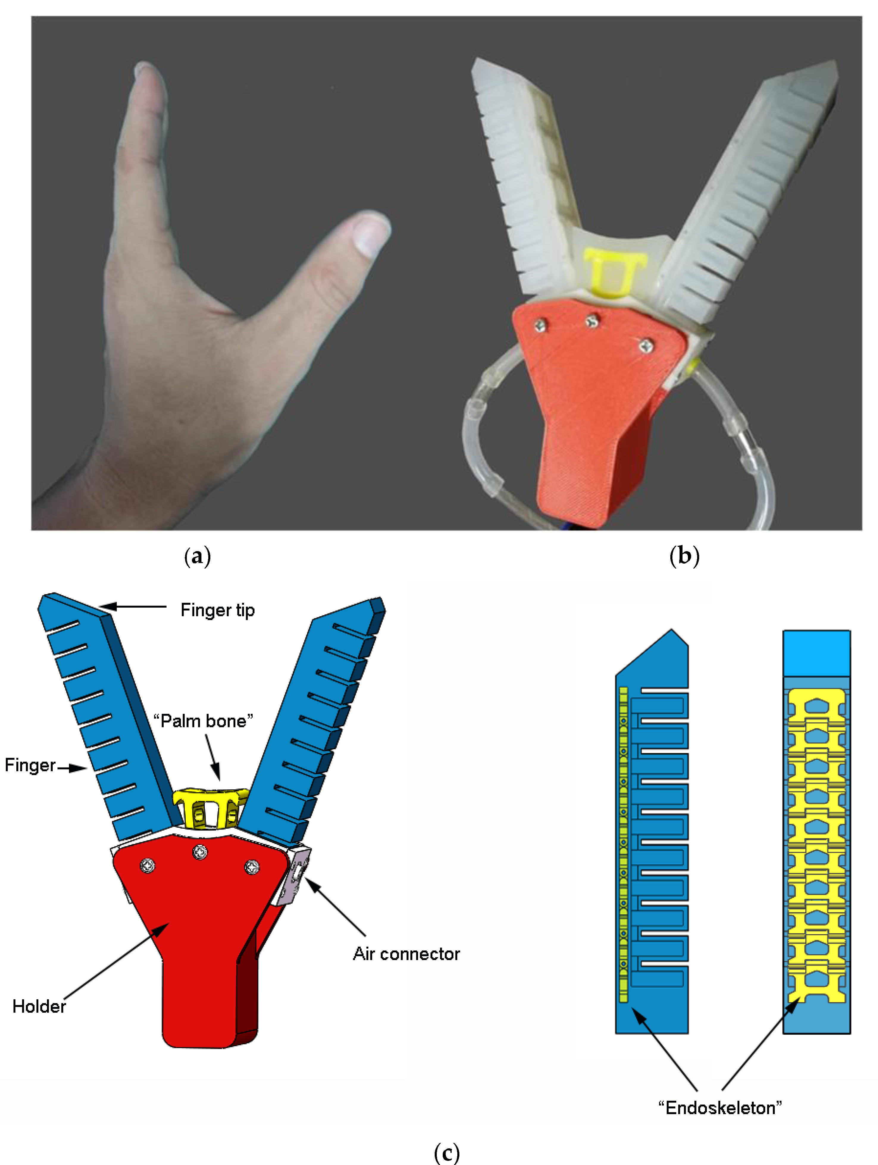
The proposed endoskeleton soft pneumatic gripper is a bionic design of the human index finger and thumb, as shown in
Figure 1a. It can imitate the pinching grasping mode of small objects with fingertips and the enveloping grasping mode of large objects with fingers and palms without changing the effective length of the gripper. The gripper consists of fingers, palm, holder, air connector, and other components, as shown in
Figure 1b. Two fingers and palm have endoskeletons which are highlighted by yellow color and provide a certain support for the soft silicone rubber. The position of the endoskeleton in the finger is illustrated by side view and back view on the right side of
Figure 1c, where the color of the soft silicone material is set to semitransparent.
2.2. Finger
The human phalange contains hard materials such as mineral components and hydroxyapatite, enabling fingers to withstand different kinds of forces, torques, and bending moments, while the flesh and skin that surround the bones allow soft and compliant interacting with the grasped object. The endoskeleton used in the finger of the soft pneumatic gripper is similar to a watch chain, as shown in
Figure 2. Each chain segment is connected by a pin. The hinge structure allows free rotation around the pin, but restricts other relative movements between neighboring segments. The chain segment was fabricated by a 3D printer using CR-PLA material with the 100% filling density. The printing speed was 50 mm/s and the nozzle temperature was 210 °C. The endoskeleton of each finger included ten segments and nine pins. In order to ensure that the endoskeleton and silicone gel have more contact surface and do not separate under the action of air pressure and external load, the chain segment was designed as a hollow structure with recessed sides and round corners. A certain gap was left between the neighboring segments to allow the silicone gel to fill, so as to buffer the movement and avoid wear during the gripping process.
Most soft pneumatic grippers in the literature use three or four fingers to grasp objects together [
27]. In the current design, two rapid type fingers were designed based on the optimized geometric results for soft pneumatic grippers [
28,
29]. The fingertip was trimmed with inclined surfaces to increase interacting surface area when performing fingertip pinching action. The length, width, and height of a single finger were 120 mm, 20 mm, and 22 mm, respectively. The fabrication process of the finger includes three stages: mainbody molding, bottom layer molding, and assembly, as shown in
Figure 3. The mixed Dragon Skin 30 material was first deaerated at 1 MPa in a vacuum deaerator for about 10 min. When the air connector was placed in the lower part of the main body mold, the upper mold part was assembled with the lower part. The deaerated silicone gel solution was then slowly poured into the mold and kept at 50 °C. After two hours, the main body of the finger could be taken out. For the bottom layer, the silicone gel solution was poured into the layer mold with a thickness of 5 mm. When the silicone gel was about to solidify, the endoskeleton was placed on top of the gel, then the remaining silicone was poured. Finally, the main body and the bottom layer were glued together with silicone gel.
2.3. Palm
When gripping large objects, the palm can act as the third supporting pivot in addition to two fingers. This increases the contact area between the gripper and the object, and stabilizes the gripping process. The front end of the palm has a curved surface, imitating the shape between the thumb and index finger of the human hand, shown in
Figure 4a. When no air pressure is applied, the palm and the fingers keep a certain distance. The endoskeleton inside the palm was made by 3D printing, as illustrated in
Figure 4b; the structure was also hollow, which facilitated the penetration of the silicone gel solution and ensured good bonding between soft and hard materials during deformation. The round hole in the palm bone allows the palm to be connected with the holder by screw. The distance from the center of the hole to the arc is 25 mm. During the fabrication process, the palm bone was placed in the mold, and the mold was filled with the silicone gel solution. The palm assembly is shown in
Figure 4c.
2.4. Holder
The fingers in soft pneumatic grippers often are fixed to the holder in a parallel manner. When the gripping object is larger than the size encircled by fingers, negative pressure has to be applied, to bend the finger outwards, compensating for insufficient size. In order to simplify the air pressure source and increase adaptivity to various objects, the proposed gripper has two fingers at an angle of 60°. The holder where the fingers are attached is shown in
Figure 5. It was composed of three parts: (a) finger connector; (b) plate; (c) holder main body, which were assembled by screws. The soft pneumatic gripper can be installed to robotic arms or other devices through the square hole in the main body.
3. Motion Analysis
It is assumed that the silicone gel material in the gripper is uniform, and the air pressure is evenly distributed on the internal wall of the air chamber. In the current gripper design, the chain-type endoskeleton in the finger restricts elongation in its length direction due to a hinge joint. The rotation of the finger can only occur around the hinges. Taking one hinge as the study object, the plane passing through the hinge in the bottom layer of the finger can be seen as the neutral plane when the finger is under bending. When pressure is applied, the rotation of the finger is illustrated in
Figure 6. Due to the presence of the endoskeleton, the finger can be divided into multiple segments. Under the action of internal air pressure, the bending moment around the hinge will be generated. The silicone gel below the hinge is under compression and the main body is stretched. According to Euler–Bernoulli law [
30], the relationship between bending moment and radius is expressed by the following equation.
where
r represents the bending radius, and
is the bending moment. The moment of inertia
of cross-sectional area
with respect to the square of
axis is
Referring to the cross sections C
1 and C
2 in
Figure 6, the bending moment at the
ith hinge is generated by the air pressure
acting on the surface area
.
Assuming the arc length in the neutral plane for the hinge
is
, the relationship between bending angle and arc length is obtained:
Combining (1) and (4), the angle
formed by the curved arc at the ith hinge becomes
The bending angle
of the entire endoskeleton finger is the sum of the angle at each hinge.
Since it is difficult to directly measure
during the experiment, the angle
is used instead of
. The geometric relationship between them is
We combine (6) and (7) to obtain the easy-to-measure bending angle relationship:
When the air pressure is increased to a certain value, the fingertips will touch each other; if the angle
is properly calculated, the inclined surfaces in the fingertips can be in full contact and can be used to pinch lightweight objects. The schematic diagram of the fingertip contact of the finger is shown in
Figure 7. The mathematical relationship between the arc length and the chord length is as follows:
Because
, the above equation can be simplified to
For current gripper design, = 25 mm, = 100 mm, = 20 mm, = 30°, and the maximum bending angle of a single finger, , is 46.2°.
4. Numerical Model
The finite element method was used to simulate the finger bending action under internal pressure. The model was meshed in ABAQUS with 3D solid elements, C3D10H, which is a 10-node hybrid quadratic tetrahedron element, as shown in
Figure 8a. A total number of 3063 nodes and 44,576 elements was employed in the model. Hinge connection type was chosen for the connection between the endoskeleton segments, and the pin was connected with the pin hole in the endoskeleton by kinematic coupling constraint. The end surface of the endoskeleton finger was fixed, and pressure was applied on the internal surfaces in the air chambers.
The endoskeleton was made from CR-PLA material, with a Young’s modulus of 3 GPa and a Poisson’s ratio of 0.25 [
31]. The soft material in the gripper was Dragon Skin 30 silicone gel, with a hardness of 30A and a Poisson’s ratio of 0.49. To describe the hyperplastic behavior of Dragon Skin 30, the Yeoh strain energy model was adopted.
where
W is strain energy density, I
1, I
2, and I
3 are the three invariants of the left Gauchy–Green deformation tensor, and
C10,
C20, and
C30 are material constants. The tensile test as per ASTM/D 412-16 was performed to obtain the stress and strain relationship. The Yeoh material model parameters were then derived by curve fitting the experimental data, as shown in
Figure 8b. The curve fitting was automatically performed in ABAQUS by inputting the experimental results. The constants
C10 = 0.118,
C20 = −0.009, and
C30 = 0.001 were calculated with a correlation coefficient of 0.990.
5. Parameter Optimizations
There are many factors that affect the bending performance, such as the height, the wall thickness, and the spacing of the air cavity. The orthogonal test method was used to study the effects of the above factors and optimize the cavity geometry of the pneumatic finger. The finger width of 20 mm, the finger length of 120 mm, and the number of air cavities were kept unchanged. Firstly, the SolidWorks 3D modeling software was used to model the nine groups of orthogonal test models, and the factors and parameters are shown in
Table 1. Then, the ABAQUS finite element simulation software was used to conduct simulation analysis. The pressure applied in the air cavity of each model was 40 kPa. Data analysis was conducted, as shown in
Table 2. The air pressure applied in the air cavity of each model was 40 kPa. The bending angles for the nine models are shown in
Table 2. In order to reflect the trend changes of each level under different factors, the factors were used as the abscissa, and the bending angle was plotted against the factor and level in
Figure 9.
The wall thickness had the highest influence on the bending angle, followed by height and spacing. The optimal level of each factor corresponds to the largest value of k
i in each column. As can be seen from
Figure 9, the optimal solution is A
1B
1C
3, that is, the air cavity spacing is 1.5 mm, the wall thickness is 1.5 mm, and the air cavity height is 14 mm. The test number for the optimal parameter combinations was defined as the 10th group. The 10th group yielded the greatest bending angle, 65.2°.
6. Gripping Performance
Experimental tests were carried out to investigate the enveloping grasp and pinch grasp with objects of different size and weight. The effect of pressure applied on finger bending angle and fingertip force was analyzed by both experiment and FE method. The experimental air pressure was supplied by U601G air pump (Ustar Model Tools Co., Ltd., Guangzhou, China), which can only generate positive pressure with a maximum value of 410 kPa. The pressure regulating valve is IR1000-01BG (AFR Company), providing a stable air pressure which was displayed on a DP-101 monitor (Panasonic Corporation).
6.1. Finger Bending Test
The deformed finger shape under different air pressure with stress contour by FEA analysis is shown in
Figure 10. It can be seen that, with pure internal pressure loading, the air chamber and hinge zone were highly stressed, while the silicone gel remote from the hinge in the bottom layer showed very low stress. The experimental test of the finger bending is presented in
Figure 11a, establishing x–y coordinates with the end of the finger and the right side of the finger as the origin. The angle between the line connecting the fingertip to the origin and the y-axis is the bending angle
. By entering different air pressures, the bending angle
of the finger is obtained. The plot of air pressure against bending angle is presented in
Figure 11b. The predicted bending angles were lower than experimentally measured angles; the difference increased at higher pressure. When the air pressure increased, the finger bending angle gradually increased and reached 75° at 40 kPa. The mathematical relationship of air pressure and bending angle was obtained by curve fitting the experimental data with a second-order polynomial:
where
is the air pressure, kPa.
As mentioned in
Section 3, the theoretical bending angle when both fingertip surfaces in full contact is 46.2°. This is consistent with the experimental results where under air pressure load of 30 kPa, the bending angle was about 46° and the fingertips were in full contact. When examining the simulation results in
Figure 12, the bending angle was about 42°, slightly smaller than the theoretical value, but the fingertip was in contact as well. If the air pressure is increased, the clamping force can be generated, which is beneficial to the fingertips to pinch the object.
6.2. Fingertip Force Test
The magnitude of the fingertip force affects the effectiveness of the gripper pinch action. The fingertip force was assessed through experiment, illustrated in
Figure 13a. The end of the finger was fixed, and the fingertip was in contact with a force sensor. The measured forces were displayed and recorded when different air pressures were applied. The fingertip forces are plotted against air pressure in
Figure 13b. The curve for the finger without endoskeleton was also tested for comparison. As the pressure increased, the fingertip force increased, but the endoskeleton gripper provided greater forces at the same pressure. Generally, the fingertip force of the endoskeleton gripper was about 1.45 times higher than that of the pure silicone gel gripper. By curve fitting, the mathematical equation for the relationship between fingertip force and air pressure is expressed as
6.3. Gripping Experiment
As a result of the endoskeleton, the gripper finger can resist lateral loading. Therefore, the pneumatic gripper can be placed either parallel or perpendicular to the ground to assess the gripping performance. Objects with different size were gripped by different parts of the gripper, fingertip, finger bottom layer, and palm. For small objects with low weight, it was desirable to use the pinching grasp with fingertips, while for objects with larger size and heavier weight, the enveloping grasp with the fingers and palm were used to have a more stable gripping state.
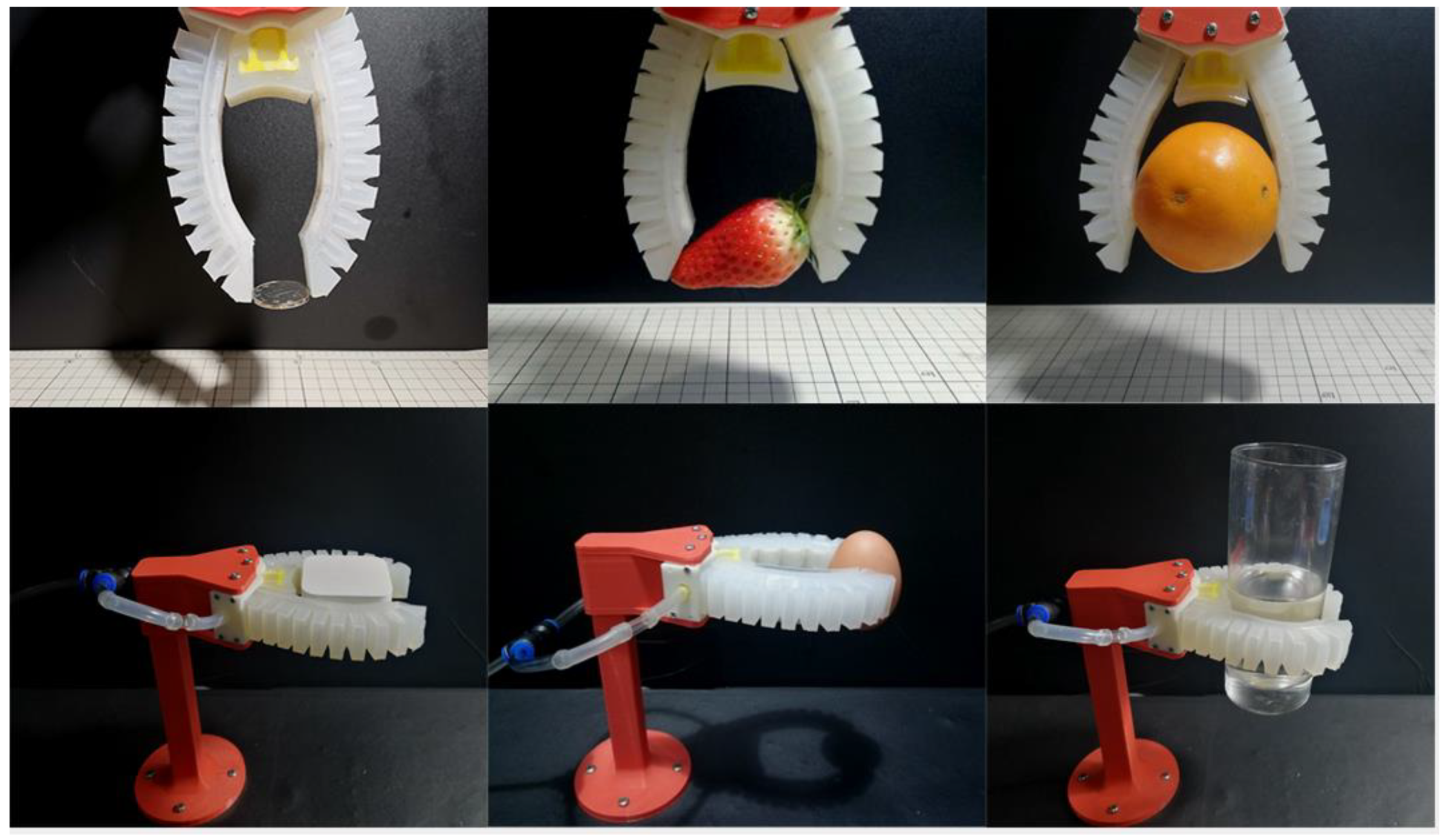
The fingertip gripping experiment is shown in
Figure 14. The tested objects, size, and weight are tabulated in
Table 3. The object size was measured by the maximum distance between the two fingers when they were in contact with the object. The range of the object size was 25.0–80.5 mm, and the weight was 6–450 g. In all cases, the air pressure required for gripping was less than 100 kPa. The object weight that can be gripped was also affected by the size and shape of the object and the friction coefficient at the interface between the silicone rubber and object. For smaller weight and size, it is better to use the fingertip pinching grasp because the fingertip has a more flexible gripping mode and is less confined by the surrounding environment. The enveloping grasp with both finger and palm can withstand a higher weight and larger size, and provide a more stable holding.
7. Conclusions
A soft pneumatic gripper inspired by the gripping action of human thumb and index finger was proposed. The gripper finger was embedded with chain-type endoskeletons, allowing free bending in the working plane but resisting out-of-plane bending. The endoskeleton gripper increased the stiffness, while maintaining the advantages of a soft gripper, i.e., flexibility and compliance. The fingertip force of the endoskeleton gripper was around 1.45 times higher than that of the gripper without endoskeleton.
The gripper successfully gripped objects from 2 mm to 80.5 mm, which was 2% to 80.5% of the gripper finger length. The object weight that the gripper can support was mainly dependent on the friction coefficient between the object and silicone gel. A maximum weight of 450 g was achieved, which was six times heavier than the finger self-weight.
Objects of various shapes, such as square, spherical, curved, cylindrical, and ellipsoidal, can be gripped. During the gripping process, the gripping position and angle can be adjusted according to the surrounding environment of the object. For objects with larger weight and shape, the enveloping grasping mode with fingers and palm had higher stability, and for objects with smaller weight and shape, the use of fingertips to pinch had greater flexibility.
Although the gripper finger achieved the targeted function, the current gripper design has only two fingers. Grasping of some complex geometric objects may not be stable under high-speed movement; it is desirable to design a gripper/hand with multiple fingers in the future work.
Author Contributions
H.L.: conceptualization, methodology, writing—original draft, writing—review and editing, supervision, project administration, fund acquisition. D.X.: investigation, writing—review and editing. Y.X.: investigation, software, writing—original draft. All authors have read and agreed to the published version of the manuscript.
Funding
This work was supported by Zhejiang Province Public Welfare Technology Application Research Project (Grant No. LGJ21E050001).
Institutional Review Board Statement
Not applicable.
Informed Consent Statement
Not applicable.
Data Availability Statement
Not applicable.
Conflicts of Interest
The authors declare that they have no known competing financial interests or personal relationships that could have appeared to influence the work reported in this paper.
References
- Laschi, C.; Cianchetti, M.; Mazzolai, B.; Margheri, L.; Follador, M.; Dario, P. Soft robot arm inspired by the octopus. Adv. Robot. 2012, 26, 709–727. [Google Scholar] [CrossRef]
- Ilievski, F.; Mazzeo, A.D.; Shepherd, R.E.; Chen, X.; Whitesides, G.M. Soft robotics for chemists. Angew. Chem. Int. Ed. 2011, 50, 1890–1895. [Google Scholar] [CrossRef] [PubMed]
- Jittungboonya, P.; Maneewan, T. Tube-Feet Inspired Soft Gripper. In Proceedings of the 9th Thai-Society-of-Mechanical-Engineers International Conference on Mechanical Engineering (TSME-ICoME), Phuket, Thailand, 11–14 December 2018. [Google Scholar]
- Guo, Z.H.; Sun, Z.S.; Li, X.N. Design and Fabrication of Pneumatic Soft Gripper. In Proceedings of the ASME International Mechanical Engineering Congress and Exposition (IMECE2018), Pittsburgh, PA, USA, 9–15 November 2018. [Google Scholar]
- Shepherd, R.F.; Stokes, A.A.; Nunes, R.M.D.; Whitesides, G.M. Soft machines that are resistant to puncture and that self seal. Adv. Mater. 2013, 25, 6709–6713. [Google Scholar] [CrossRef] [PubMed]
- Elgeneidy, K.; Lohse, N.; Jackson, M. Bending angle prediction and control of soft pneumatic actuators with embedded flex sensors-A data-driven approach. Mechatronics 2018, 5, 234–247. [Google Scholar] [CrossRef]
- Wang, H.B.; Totaro, M.; Beccai, L. Toward perceptive soft robots: Progress and challenges. Adv. Sci. 2018, 5, 1800541. [Google Scholar] [CrossRef]
- Yang, Y.; Li, Y.T.; Chen, Y.H. Principles and methods for stiffness modulation in soft robot design and development. Bio-Des. Manuf. 2018, 1, 14–25. [Google Scholar] [CrossRef]
- Culha, U.; Hughes, J.; Rosendo, A.; Giardina, F.; Iida, F. Design principles for soft-rigid hybrid manipulators. In Biosystems and Biorobotics; Springer: Cham, Switzerland, 2017; pp. 87–94. [Google Scholar]
- Paez, L.; Agarwal, G.; Paik, J. Design and analysis of a soft pneumatic actuator with origami shell reinforcement. Soft Robot. 2016, 3, 109–119. [Google Scholar] [CrossRef]
- Zhou, J.S.; Chen, X.J.; Li, J.; Tian, Y.N.; Wang, Z. A Soft Robotic Approach to Robust and Dexterous Grasping. In Proceedings of the 2018 IEEE-RAS International Conference on Soft Robotics (RoboSoft), Livorno, Italy, 24–28 April 2018; pp. 412–417. [Google Scholar]
- Wei, Y.; Chen, Y.H.; Ren, T.; Chen, Q.; Yan, C.X.; Yang, Y.; Li, Y.T. A novel, variable stiffness robotic gripper based on integrated soft actuating and particle jamming. Soft Robot. 2016, 3, 134–143. [Google Scholar] [CrossRef]
- Park, W.; Seo, S.; Bae, J. A hybrid gripper with soft material and rigid structures. IEEE Robot. Autom. Let. 2019, 4, 65–72. [Google Scholar] [CrossRef]
- Park, W.; Seo, S.; Bae, J. Development of a hybrid gripper with soft material and rigid structures. In Proceedings of the 2018 IEEE/RSJ International Conference on Intelligent Robots and Systems (IROS), Madrid, Spain, 1–5 October 2018; pp. 5930–5935. [Google Scholar]
- Sun, T.; Chen, Y.L.; Han, T.Y.; Jiao, C.L.; Lian, B.B.; Song, Y.M. A soft gripper with variable stiffness inspired by pangolin scales, toothed pneumatic actuator and autonomous controller. Robot. CIM-INT Manuf. 2020, 61, 101848. [Google Scholar] [CrossRef]
- Glick, P.; Suresh, S.A.; Ruffatto, D.; Cutkosky, M.; Tolley, M.T.; Parness, A. A soft robotic gripper with gecko-inspired adhesive. IEEE Robot. Autom. Let. 2018, 3, 903–910. [Google Scholar] [CrossRef]
- Zhou, J.S.; Chen, S.; Wang, Z. A soft-robotic gripper with enhanced object adaptation and grasping reliability. IEEE Robot. Autom. Let. 2017, 2, 2287–2293. [Google Scholar] [CrossRef]
- Tiziani, L.; Hart, A.; Cahoon, T.; Wu, F.Y.; Asada, H.H.; Hammond, F.L. Empirical characterization of modular variable stiffness inflatable structures for supernumerary grasp-assist devices. Int. J. Robot. Res. 2017, 36, 1391–1413. [Google Scholar] [CrossRef]
- Shahid, Z.; Glatman, A.L.; Ryu, S.C. Design of a soft composite finger with adjustable joint stiffness. Soft Robot. 2019, 6, 722–732. [Google Scholar] [CrossRef] [PubMed]
- Yang, Y.; Chen, Y.H.; Li, Y.T.; Chen, M.Z.Q.; Wei, Y. Bioinspired robotic fingers based on pneumatic actuator and 3d printing of smart material. Soft Robot. 2017, 4, 147–162. [Google Scholar] [CrossRef]
- Chen, J.; Chen, B.D.; Han, K.; Tang, W.; Wang, Z.L. A triboelectric nanogenerator as a self-powered sensor for a soft-rigid hybrid actuator. Adv. Mater. Technol. 2019, 4, 1900337. [Google Scholar] [CrossRef]
- Yang, Y.; Zhang, Y.Z.; Kan, Z.C.; Zeng, J.L.; Wang, M.Y. Hybrid jamming for bioinspired soft robotic fingers. Soft Robot. 2020, 7, 292–308. [Google Scholar] [CrossRef] [PubMed]
- Subramaniam, V.; Jain, S.; Agarwal, J.; Alvarado, P.V.Y. Design and characterization of a hybrid soft gripper with active palm pose control. Int. J. Robot. Res. 2020, 39, 1668–1685. [Google Scholar] [CrossRef]
- Hao, Y.F.; Gong, Z.Y.; Xie, Z.X.; Guan, S.Y.; Yang, X.B.; Wang, T.M.; Wen, L. A soft bionic gripper with variable effective length. J. Bionic. Eng. 2018, 15, 220–235. [Google Scholar] [CrossRef]
- Wu, Z.; Li, X.; Guo, Z. A Novel Pneumatic Soft Gripper with a Jointed Endoskeleton Structure. Chin. J. Mech. Eng. 2019, 32, 1–20. [Google Scholar] [CrossRef] [Green Version]
- Mosadegh, B.; Polygerinos, P.; Keplinger, C.; Wennstedt, S.; Shepherd, R.F.; Gupta, U.; Shim, J.; Bertoldi, K.; Walsh, C.J.; Whitesides, G.M. Pneumatic networks for soft robotics that actuate rapidly. Adv. Funct. Mater. 2014, 24, 2163–2170. [Google Scholar] [CrossRef]
- Li, S.; Bai, H.D.; Shepherd, R.F.; Zhao, H.C. Bio-inspired design and additive manufacturing of soft materials, machines, robots, and haptic interfaces. Angew. Chem. Int. Edit 2019, 58, 11182–11204. [Google Scholar] [CrossRef] [PubMed]
- Hu, W.P.; Mutlu, R.; Li, W.H.; Alici, G. A structural optimisation method for a soft pneumatic actuator. Robotics 2018, 7, 24. [Google Scholar] [CrossRef]
- Moseley, P.; Florez, J.M.; Sonar, H.A.; Agarwal, G.; Curtin, W.; Paik, J. Modeling, design, and development of soft pneumatic actuators with finite element method. Adv. Eng. Mater. 2016, 18, 978–988. [Google Scholar] [CrossRef]
- Alici, G. An effective modelling approach to estimate nonlinear bending behaviour of cantilever type conducting polymer actuators. Sensor Actuat. B Chem. 2009, 141, 284–292. [Google Scholar] [CrossRef]
- Iwatake, A.; Nogi, M.; Yano, H. Cellulose nanofiber-reinforced polylactic acid. Compos. Sci. Technol. 2008, 68, 2103–2106. [Google Scholar] [CrossRef]
| Publisher’s Note: MDPI stays neutral with regard to jurisdictional claims in published maps and institutional affiliations. |
© 2022 by the authors. Licensee MDPI, Basel, Switzerland. This article is an open access article distributed under the terms and conditions of the Creative Commons Attribution (CC BY) license (https://creativecommons.org/licenses/by/4.0/).


