

A Hybrid Control Strategy for a PMSM-Based Aircraft Cargo Door Actuator

Abstract
:1. Introduction
2. System and Load Model
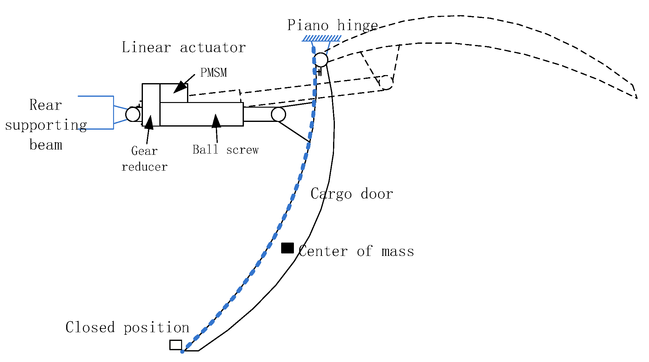
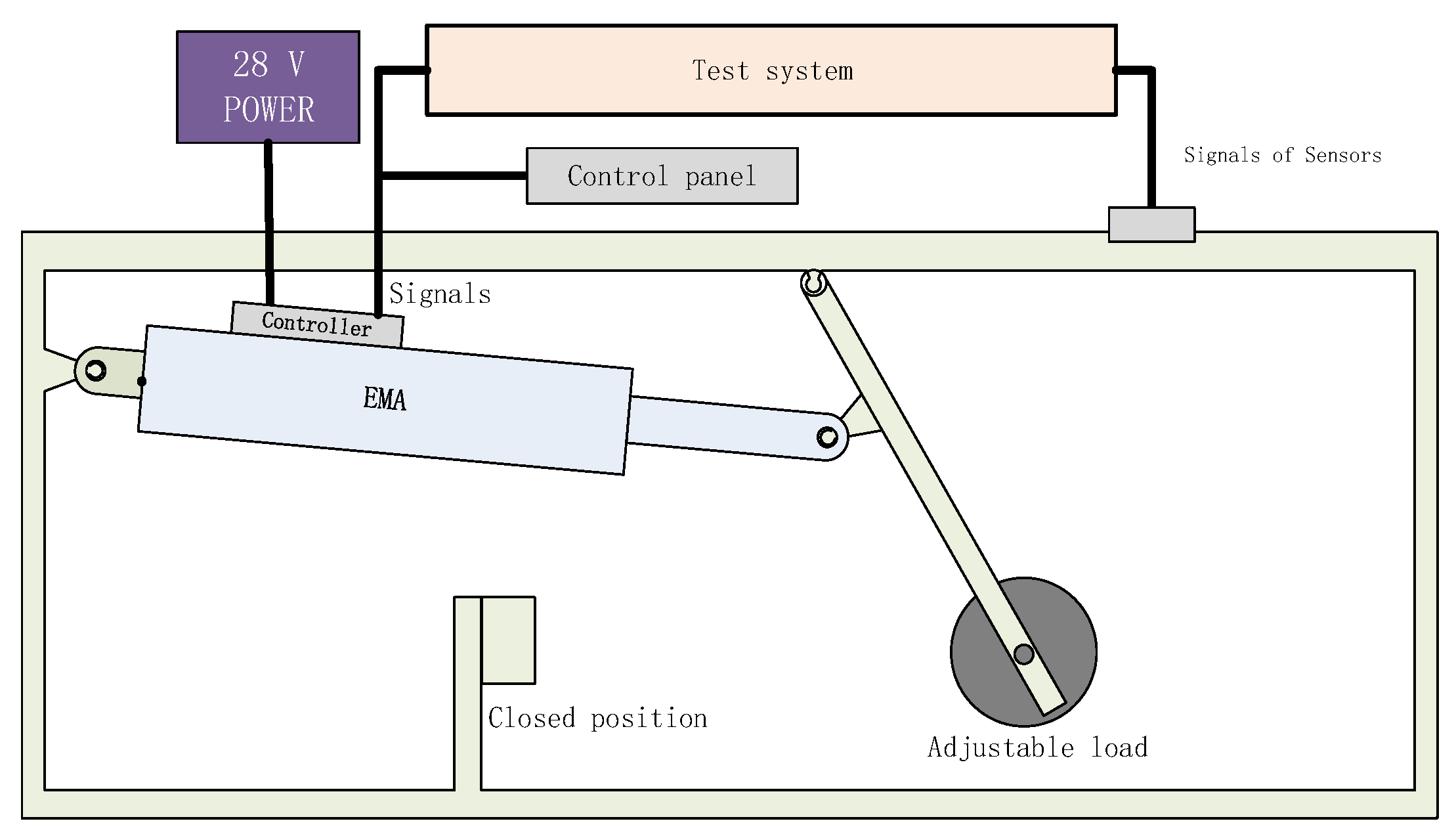
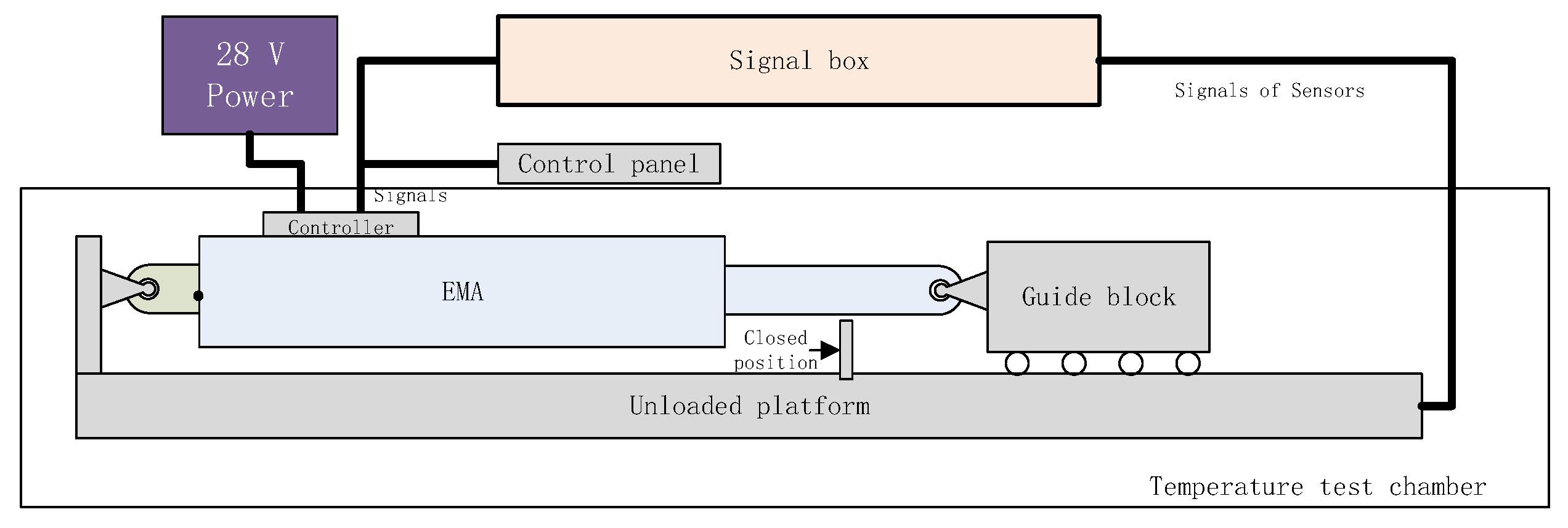
2.1. System Architecture
2.2. PMSM-Based EMA Model
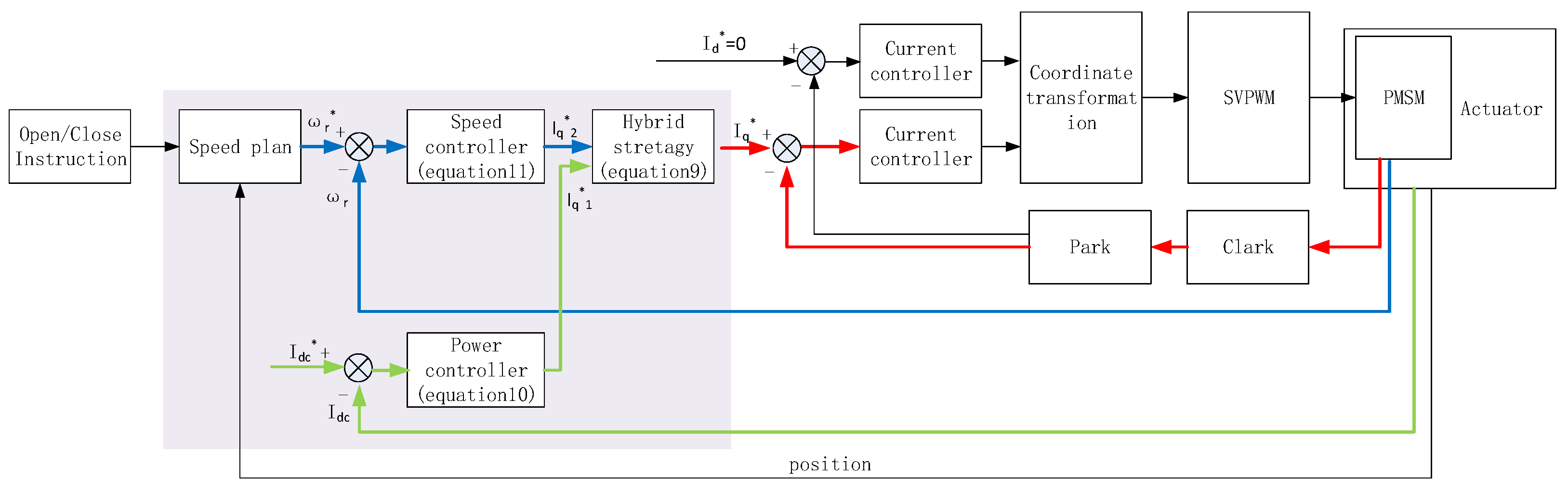
3. Control Strategy
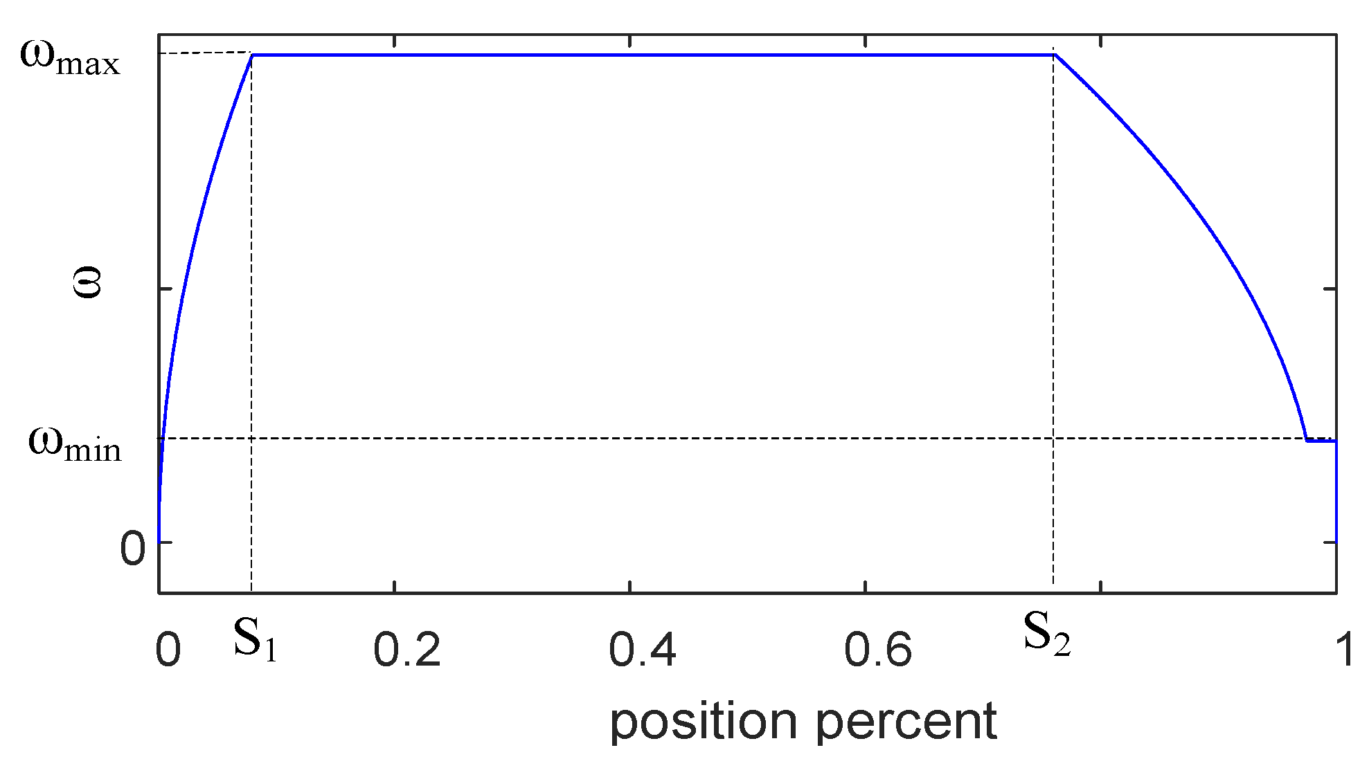
3.1. Speed Curve
3.2. Hybrid Control Strategy
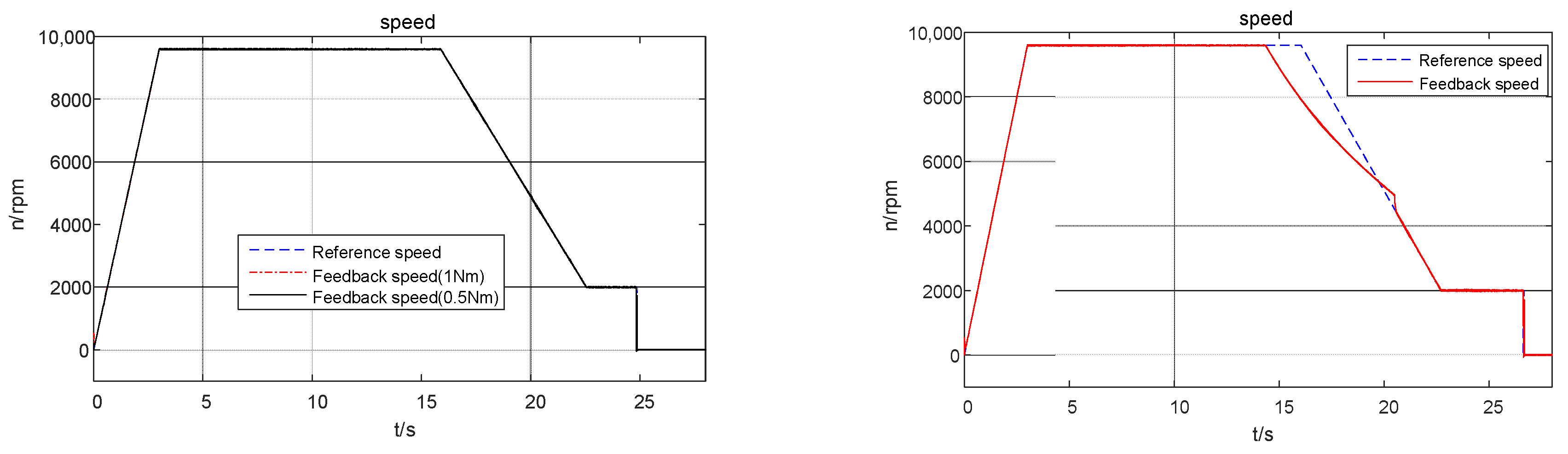
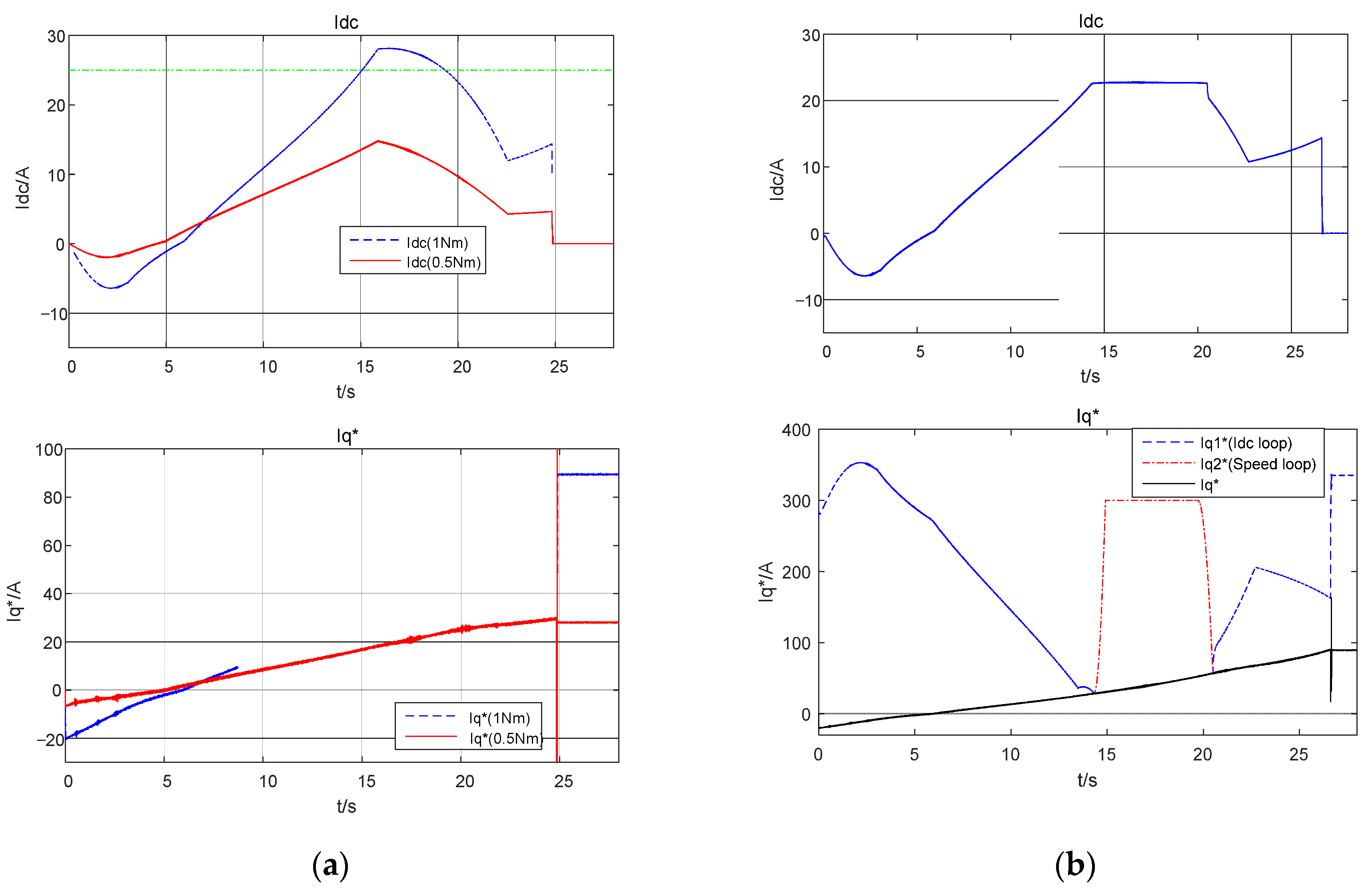
4. Simulation
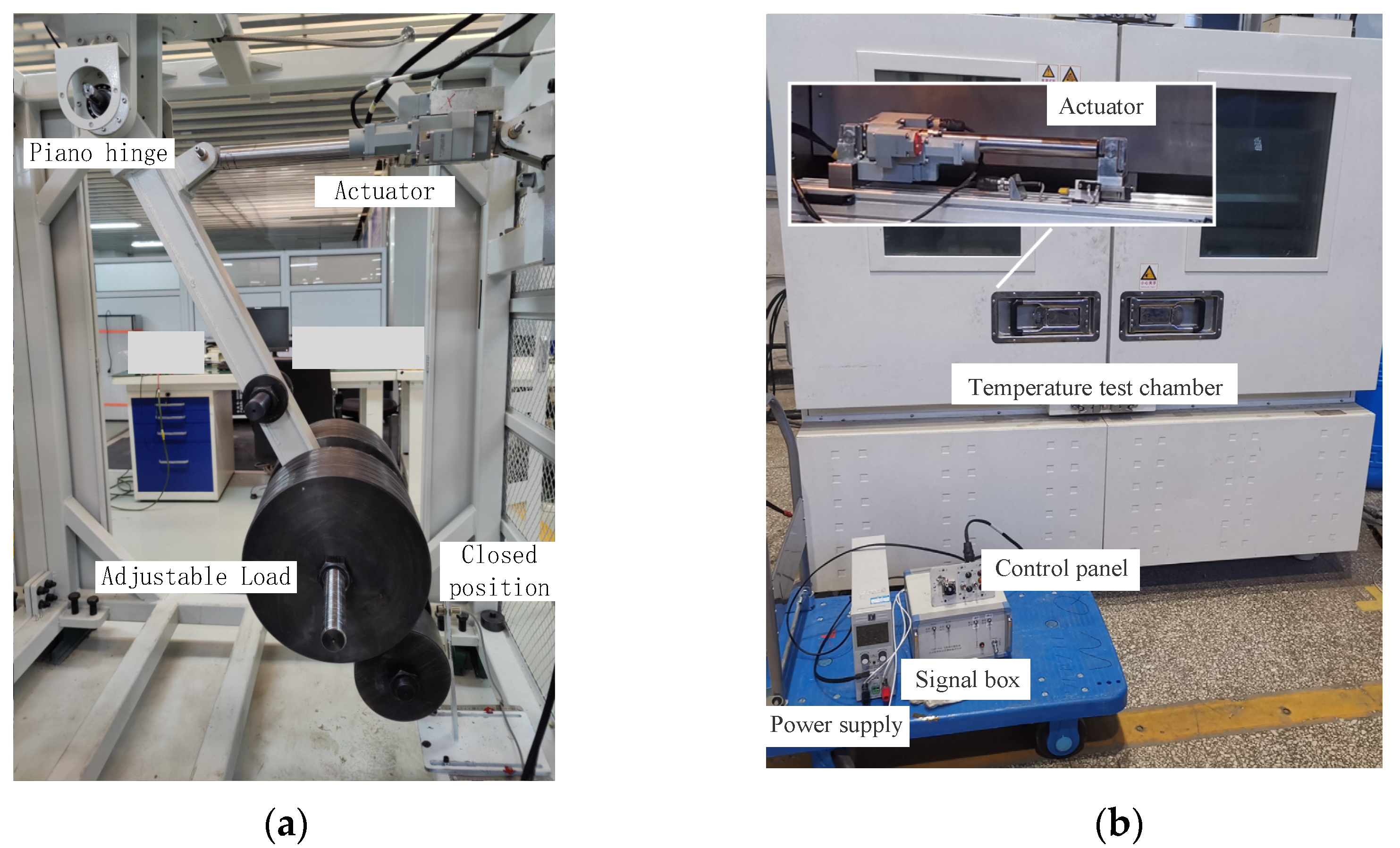
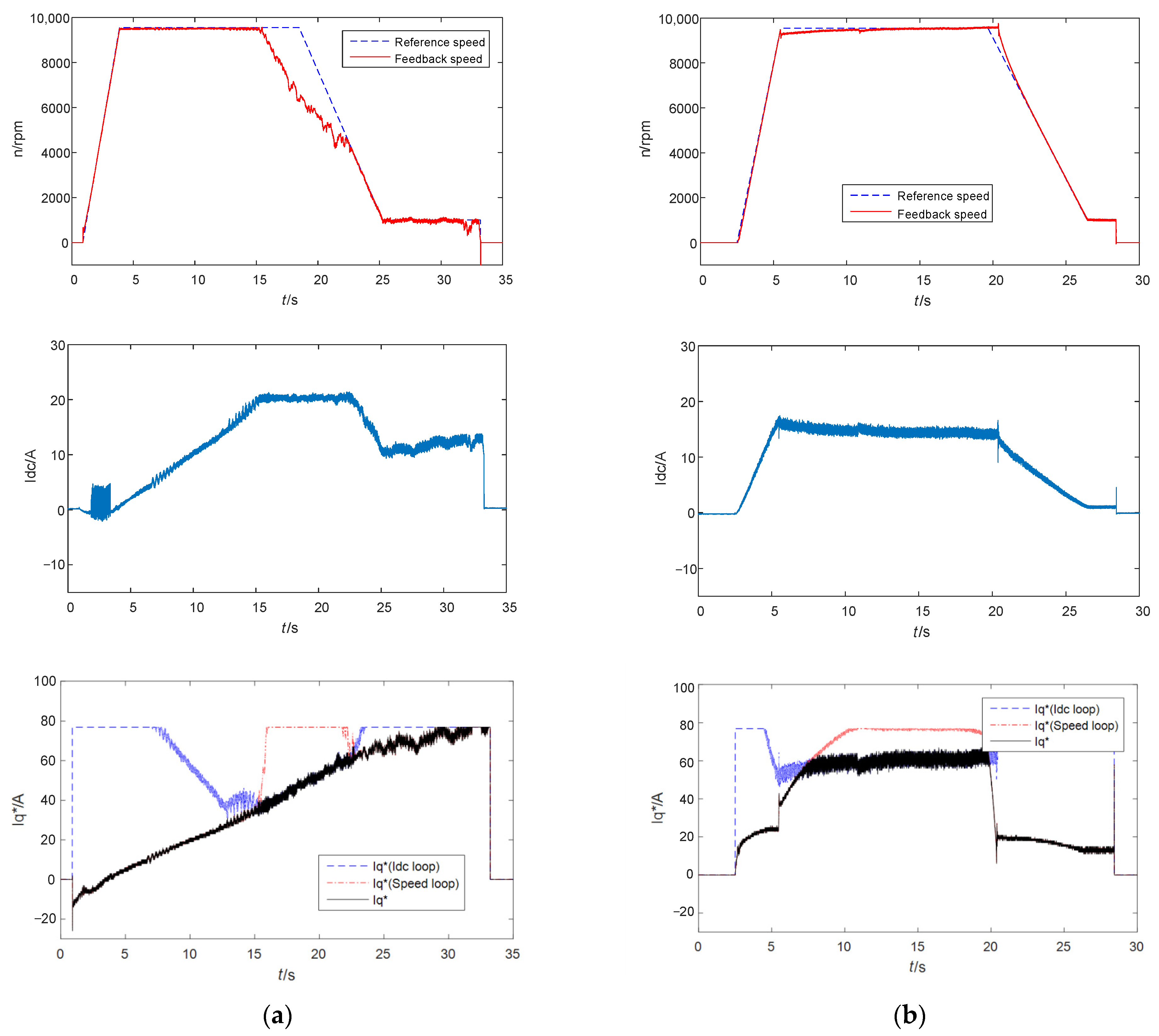
5. Experiments
6. Conclusions
Author Contributions
Funding
Institutional Review Board Statement
Informed Consent Statement
Data Availability Statement
Conflicts of Interest
References
- Sayed, E.; Abdalmagid, M. Review of Electric Machines in More-/Hybrid-/Turbo-Electric Aircraft. IEEE Trans. Transp. Electrif. 2021, 7, 2976–3005. [Google Scholar] [CrossRef]
- Giangrande, P.; Galassini, A. Considerations on the Development of an Electric Drive for a Secondary Flight Control Electromechanical Actuator. IEEE Trans. Ind. Appl. 2019, 55, 3544–3554. [Google Scholar] [CrossRef]
- Volpato Filho, C.J.; Xiao, D.; Vieira, R.P.; Emadi, A. Observers for High-Speed Sensorless PMSM Drives: Design Methods, Tuning Challenges and Future Trends. IEEE Access 2021, 9, 56397–56415. [Google Scholar] [CrossRef]
- Xue, Z.; Wang, Y.; Li, L.; Wang, X. An Adaptive Speed Control Method Based on Deep Reinforcement Learning for Permanent Magnet Synchronous Motor. In Proceedings of the 2021 Chinese Intelligent Systems Conference, Fuzhou, China, 16–17 October 2021. [Google Scholar]
- Peng, W.; Lan, Y.; Chen, S.; Lin, F.; Chang, R. Reinforcement Learning Control for Six-Phase Permanent Magnet Synchronous Motor Position Servo Drive. In Proceedings of the 2020 IEEE International Conference on Knowledge Innovation and Invention (ICKII), Kaohsiung, Taiwan, 21–23 August 2020. [Google Scholar] [CrossRef]
- Cai, W.; Wu, X. Review and Development of Electric Motor Systems and Electric Powertrains for New Energy Vehicles. Automot. Innov. 2021, 4, 3–22. [Google Scholar] [CrossRef]
- Peng, Z. Analysis and Implementation of Constrained MTPA Criterion for Induction Machine Drives. IEEE Access 2020, 8, 176445–176453. [Google Scholar] [CrossRef]
- Xu, W.; Junejo, A.K. An Efficient Antidisturbance Sliding-Mode Speed Control Method for PMSM Drive Systems. IEEE Trans. Power Electron. 2021, 36, 6879–6891. [Google Scholar] [CrossRef]
- Yu, J.; Shi, P.; Dong, W.; Chen, B.; Lin, C. Neural Network-Based Adaptive Dynamic Surface Control for Permanent Magnet Synchronous Motors. IEEE Trans. Neural Netw. Learn. Syst. 2015, 26, 640–645. [Google Scholar] [CrossRef]
- Li, S.; Gu, H. Fuzzy Adaptive Internal Model Control Schemes for PMSM Speed-Regulation System. IEEE Trans. Ind. Inform. 2012, 8, 767–779. [Google Scholar] [CrossRef]
- Lin, P.; Wu, Z.; Liu, K.-Z.; Sun, X.-M. A Class of Linear–Nonlinear Switching Active Disturbance Rejection Speed and Current Controllers for PMSM. IEEE Trans. Power Electron. 2021, 36, 14366–14382. [Google Scholar] [CrossRef]
- Xia, J.; Li, Z.; Yu, D.; Guo, Y.; Zhang, X. Robust Speed and Current Control with Parametric Adaptation for Surface-Mounted PMSM Considering System Perturbations. IEEE J. Emerg. Sel. Top. Power Electron. 2021, 9, 2807–2817. [Google Scholar] [CrossRef]
- Xue, Z.; Li, L.; Wang, X.; Wei, S.; Guo, P.; Nie, Z. A motion control strategy of electro-mechanical actuator for cargo door based on FPGA. In Proceedings of the CSAA/IET International Conference on Aircraft Utility Systems, Online, 18–21 September 2020; pp. 463–468. [Google Scholar]
- Cao, Z.; Liu, H.; Zhou, Y.; Zhang, C. Energy optimization Charateristic Analysis of More Electric Aircraft Flight Control System. In Proceedings of the 2018 IEEE 2nd International Electrical and Energy Conference (CIEEC), Beijing, China, 4–6 November 2018; pp. 227–231. [Google Scholar]
- Alexander, R.; Meyer, D.; Wang, J. A Comparison of Electric Vehicle Power Systems to Predict Architectures, Voltage Levels, Power Requirements, and Load Characteristics of the Future All-Electric Aircraft. In Proceedings of the 2018 IEEE Transportation Electrification Conference and Expo (ITEC), Long Beach, CA, USA, 13–15 June 2018; pp. 194–200. [Google Scholar]
- Chu, J.; Hu, Y.; Huang, W.; Li, Y.; Yang, J.; Wang, M. Direct active and reactive power control of PMSM. In Proceedings of the 2009 IEEE 6th International Power Electronics and Motion Control Conference, Wuhan, China, 17–20 May 2009; pp. 1808–1812. [Google Scholar]
- Szenasy, I.; Varga, Z.; Szeli, Z. Optimum control strategy for PMSM in field-weakening region by constant power. In Proceedings of the 2015 International Conference on Electrical Systems for Aircraft, Railway, Ship Propulsion and Road Vehicles (ESARS), Aachen, Germany, 3–5 March 2015; pp. 1–6. [Google Scholar]
- Bin, W.; Mehdi, N. Control of Synchronous Motor Drive; Wiley-IEEE Press: New York, NY, USA, 2017; pp. 353–391. [Google Scholar]
- Jones, A.B. Ball Motion and Sliding Friction in Ball Bearings. ASME J. Basic Eng. 1959, 81, 1–12. [Google Scholar] [CrossRef]


| Quantity | Value | Unit |
|---|---|---|
| Rated power | 700 | W |
| Rated voltage | 28 | V |
| Rated torque | 0.3 | Nm |
| Rated speed | 10,000 | rpm |
| Flux linkage | 0.0029 | Wb |
| Stator resistance | 0.013 | Ω |
| d-axis or q-axis inductance | 0.028 × 10⁻³ | mH |
| Pole pairs | 4 | |
| Frictional resistance coefficient | 2 |
Publisher’s Note: MDPI stays neutral with regard to jurisdictional claims in published maps and institutional affiliations. |
© 2022 by the authors. Licensee MDPI, Basel, Switzerland. This article is an open access article distributed under the terms and conditions of the Creative Commons Attribution (CC BY) license (https://creativecommons.org/licenses/by/4.0/).
Share and Cite
Wang, X.; Wang, X.; Xue, Z.; Guo, P.; Liu, S. A Hybrid Control Strategy for a PMSM-Based Aircraft Cargo Door Actuator. Actuators 2022, 11, 256. https://doi.org/10.3390/act11090256
Wang X, Wang X, Xue Z, Guo P, Liu S. A Hybrid Control Strategy for a PMSM-Based Aircraft Cargo Door Actuator. Actuators. 2022; 11(9):256. https://doi.org/10.3390/act11090256
Chicago/Turabian StyleWang, Xin, Xiaolu Wang, Zhao Xue, Peng Guo, and Shuai Liu. 2022. "A Hybrid Control Strategy for a PMSM-Based Aircraft Cargo Door Actuator" Actuators 11, no. 9: 256. https://doi.org/10.3390/act11090256
APA StyleWang, X., Wang, X., Xue, Z., Guo, P., & Liu, S. (2022). A Hybrid Control Strategy for a PMSM-Based Aircraft Cargo Door Actuator. Actuators, 11(9), 256. https://doi.org/10.3390/act11090256