Article

Motion Analysis of Wire Rope Maintenance Device

School of Mechanical Engineering, Hubei University of Technology, Wuhan 430068, China
*
Author to whom correspondence should be addressed.
Actuators 2023, 12(10), 392; https://doi.org/10.3390/act12100392
Submission received: 15 September 2023 / Revised: 12 October 2023 / Accepted: 17 October 2023 / Published: 19 October 2023
(This article belongs to the Section Actuators for Land Transport)

Abstract

:
This work outlines a design for a wire rope maintenance device that is based on commonly used, low-dropping point lubricating grease for wire rope lubrication and operates along the strand’s twist direction. Unlike similar existing devices, this device scrapes abrasives from the wire rope’s surface along the strand’s twist direction and applies lubricating grease in the same direction. It addresses issues related to the accumulation of old lubricating grease between strands, as well as the problems of a heavy weight, high traction force requirements, complex operation, unstable motion, potential surface damage to the wire rope, and the strong pollution found in existing products. The wheel system of this device was kinematically modeled and subjected to force analysis, and its accuracy was verified through simulations and experiments. Test results show that when this device is used for cleaning and lubricating wire ropes, it requires less than 150 N of traction force, maintains a stable speed of 0.6 m/s, and ensures coaxiality within ±0.1 mm, thus meeting the maintenance requirements of ropeway wire ropes. In future work, the effects of different factors, such as changes in scraper shape and size, lubricating grease application speed, and temperature and pressure inside the grease storage chamber can be studied to understand their influence on the application of grease to wire ropes.

1. Introduction

Wire rope is a key component in ropeway equipment. Due to the fact that ropeway equipment is mostly built in harsh mountainous or seaside climates, wire ropes used in ropeway often deteriorate due to large temperature and humidity changes during use. The impurities produced not only cover the surface of the wire rope, but also penetrate into the wire rope over time. During use, the wire rope also generates heat due to friction with the wire rope grip, which accelerates oxidation, carbonization, or condensation into coke, forming hard scales and abrasives. This can cause wear and tear on the wire rope’s grip jaws, as well as burrs on the inner surface, resulting in a vicious cycle.
To achieve optimal performance, most ropeway wire ropes require constant maintenance during use, usually by spraying lubrication with a spray lubrication machine once a year, but the dirt inside the wire rope cannot be removed. This approach is not only costly and inefficient, but also potentially dangerous in some situations, and often fails to achieve the desired results. Poor maintenance can lead to frequent replacement of wire ropes or even cause serious accidents due to ropeway breakage. Therefore, the study of wire rope maintenance devices can greatly improve work efficiency, reduce labor costs, and reduce the risk of using and maintaining ropeways, which is of great significance.
The research object of this paper is an overhead cableway wire rope maintenance device, which has certain differences from the maintenance of port wire ropes [1] but is similar to the structure required for climbing robots. This work primarily investigates rope-climbing robots such as the six-wheeled vertical cable-moving robot [2,3], dual-wheeled vertical rope-climbing robot [4], expandable-wheel horizontal cable obstacle-surmounting robot [5], four-wheeled horizontal cable-moving robot [6], spring-clamping-wheel inclined cable inspection robot [7,8], and pole-climbing robots with designs based on vertical poles with significant diameter variations and surface obstacles [9], as well as track-type, pole-climbing robots [10]. Their respective advantages and disadvantages are summarized. Furthermore, considering the application scenarios of this study, improvement proposals are presented based on existing climbing robot structures.
Kim, H.M., and colleagues conducted research on the design of a six-wheeled bridge cable inspection robot [11]. One of its primary advantages is the adjustable cable gripping capability during cable climbing. This is achieved by controlling the movement of the linkages through motorized forward and reverse rotations, allowing for the adjustment of the clamping force based on the cable’s surface conditions. This enables the robot to adapt to cables of different diameters. Subsequently, they improved the robot by equipping it with maintenance equipment and adding a safety landing mechanism [12]. They also modified the wheel-based structure to a track-based structure [13]. Moreover, they increased the effective payload to 9 kg, enhancing the robot’s obstacle-surmounting capabilities and stability when climbing steel ropes [14]. Finally, they conducted on-site tests at the Yong-Jong Grand Bridge in South Korea [15], discussing the actual environmental conditions of suspension bridges and other potential applications of the robot.
Fengyu Xu has developed a novel wheel-based cable inspection robot [16]. This robot is capable of climbing any inclined cable with a diameter ranging from 60 to 205 mm while maintaining stability under a load of less than 4 kg. An effective landing mechanism based on gas dampers restricts landing speed and ensures safe landing on cables inclined at 29 to 90 degrees. Furthermore, structural improvements have enabled the robot to perform inspections on typical spiral cables with diameters ranging from 100 to 205 mm [17]. The dual-sided clamping wheels have been replaced with triple-sided clamping wheels [18], determining the robot’s obstacle-passing capability and two key parameters affecting its obstacle-passing performance: wheel radius and positive pressure. A simulation was conducted for the robot’s obstacle-surmounting path and performance. In the laboratory, effective payload and obstacle-climbing experiments were conducted on the climbing robot [19], and comprehensive climbing load tests were performed under vibration conditions, with the effective payload increased to 10 kg [20].
In summary, researchers have extensively studied the application of climbing robot platforms on fixed wire ropes, but specific wire rope maintenance devices have been rarely discussed. Existing wire rope maintenance devices often require the use of elevators to scrape off old grease, which can cause significant damage to the wire rope itself. For fixed wire ropes, lubrication is typically done through spray lubrication, which cannot effectively remove dirt inside the wire rope and results in excessive lubricant waste, leading to environmental pollution.
This work outlines a design for a wire rope maintenance device that undergoes static, kinematic, and dynamic analysis to ensure the coaxiality of the lubricant application shape with the steel wire rope axis within a specified range. This guarantees that the device can move at a speed of 0.6 mm/s with a traction force below 200 N while simultaneously removing old lubricant and applying new lubricant. Distinguishing itself from existing products, this device incorporates motion along the strand’s twist direction, allowing for a more precise removal of lubricant residues between strands and preventing lubricant accumulation, as illustrated in Figure 1. Furthermore, the accuracy and stability of this device were verified through simulations and experiments. Test results show that after operating the device, the coaxiality of the lubricant coating formed on the steel wire rope surface, following cleaning and lubrication, remains within an acceptable range. Existing products typically employ large hoists to remove old lubricant from steel wire ropes, and while specific traction force values are not provided in the paper, they are significantly higher than what can be achieved manually. Compared to existing steel wire rope lubrication methods, this maintenance device offers several advantages: it is lightweight (weighing only 3 kg in total), easy for a single worker to carry, it requires only two simple installation steps, is cost-effective due to its modular design for easy component replacement, and it is safe and reliable. During operation, the device applies minimal traction force, preventing damage to the steel wire rope. Moreover, it includes a separate lubricant storage chamber to prevent lubricant wastage and environmental pollution. This device introduces a novel solution for the maintenance of ropeway steel wire ropes.
The structure of this paper is organized as follows: Section 2 introduces the structure of the wire rope maintenance device. Section 3 analyzes the static characteristics of the robot. Section 4 examines the robot’s motion characteristics. Section 5 tests the robot through simulation and experiments. Finally, Section 6 discusses the conclusions and outlines future work.

2. Structure

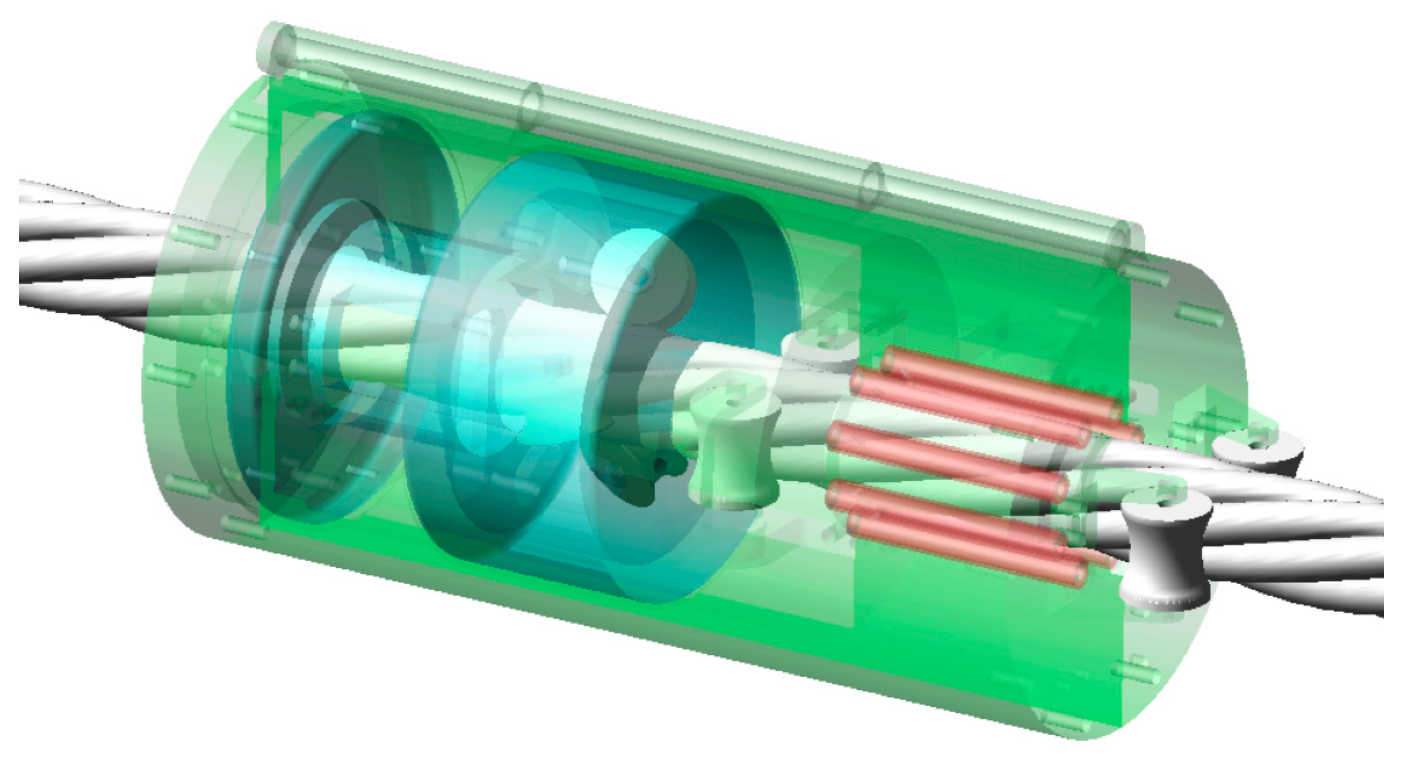
To achieve the moving mode of rotating and advancing along the twist of the wire strands, this wire rope maintenance device is mainly composed of three parts: a housing module, a heating module, and a rotor module (Figure 2). The heating module and the rotor module are fixed by the housing module, wherein the heating module softens the grease by heating, and the rotor module can rotate freely along the axial direction in the housing module to apply grease. The basic parameters of the wire rope maintenance device are shown in Table 1.
The housing module consists of two shells connected by a shaft to form an integral structure (Figure 3). The inner part of the shell is provided with a groove for fixing the rotor module. There are two guide wheels and a handle included with each shell. The housing module controls the axial movement of the entire robot on the wire rope through the guide wheels, and reduces friction through the roller wheels. The handle is provided to fix the hook and wire rope. The shell is provided with two buckles for quick installation on the wire rope. The two shells are provided with an oil inlet and an oil outlet. The old grease is extruded through the oil outlet, and the new grease is injected into the rotor module through the oil inlet.
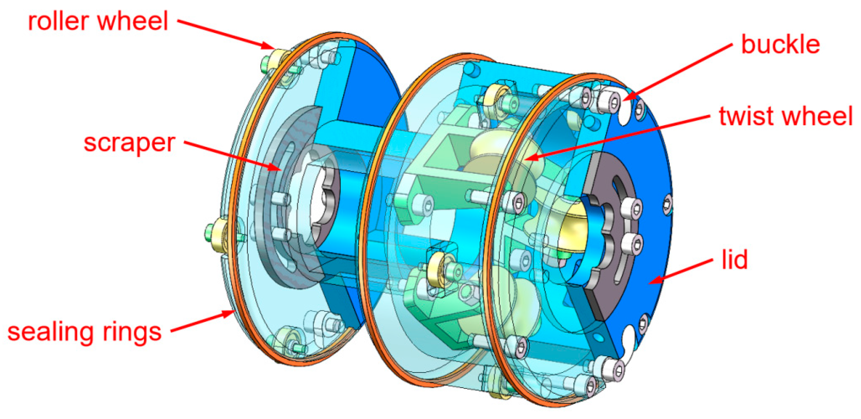
The rotor module is composed of two shells with buckles for quick installation on the wire rope (Figure 4). There are three twist wheels arranged in the rotor module to make the rotor module move along the twist of the wire strands, and two lids are arranged to protect the wheels from the grease. Both the shells and the lids are equipped with replaceable PTFE oil scraper blades. The former scrapes the old grease, while the latter shapes the new grease. The contact surface between the rotor module and the housing module is provided with three sealing rings for sealing and 10 roller wheels for reducing friction.
To prepare for maintenance, first unlock the rotor module and secure it to the wire rope. Then, place the outer shell module onto the rotor module and engage the fasteners to begin operation.

3. Static Analysis

When the wire rope maintenance device is in normal operation, the outer shell will not rotate around the wire rope. During this process, two guide wheels are symmetrically distributed on both sides of the wire rope, and the six twist wheels will rotate around the wire rope during operation due to changes in surface roughness and vibration of the wire rope. At the same time, the guide wheels play a role in preventing detachment during operation, preventing the device from accidentally detaching from the wire rope.

3.1. Static Analysis of the Guide Wheels

Taking the operational state of a wire rope maintenance device on a horizontal wire rope as an example, it is assumed that the contact points between the guide wheels and the wire rope are symmetrically distributed on both sides of the wire rope centerline CD, and the guide wheels are in a critical state, i.e., the edges of the wheels are in a separated state from the surface of the wire rope. At this time, point P is assumed to be the center of mass of the device, and the force components acting on the contact points of the two guide wheels are shown in Figure 5a.
One set of guide wheels was analyzed separately and the force analysis Figure 5b was obtained. The following equation can be obtained by balancing conditions:
N 11 = P 1 cos α + Q 1 sin α
T 1 = P 1 sin α + Q 1 cos α
By the balance conditions, the following formula can be obtained from Figure 5b:
P 1 = N 11 cos α + μ N 11 sin α
When the wire rope maintenance device is exactly in the critical state, the two guide wheels together bear half of the weight of the device, as shown in Figure 5a. By the principle of torque balance, the following formula can be obtained:
F y = 0 P 1 + P 2 = M g + a
M = 0 P 1 l 1 + l 2 = P 2 l 3
When the transverse displacement of the wire rope is too large, it may cause contact interference with the surface of the guide wheels. This acceleration can be measured using a high-speed camera to capture images and the principles of computer image processing.
According to the above formula, the critical condition for preventing the device from slipping off the wire rope is:
N 11 M g + a l 3 l 1 + l 2 + l 3 μ sin α + cos α
The critical condition for the device not to rotate with the wire rope while in operation is:
M g + a r l 1 · μ i = 1 2 N i 1 + N i 2

3.2. Static Analysis of the Twist Wheels

One set of twist wheels was analyzed separately, and the force composition of the contact point on the three twist wheels is shown in Figure 6a. Considering the equidistance between the twist wheels and the characteristic of a 120° angle, the force analysis of the twist wheels is shown in Figure 6b.
By the balance conditions, the following formula can be obtained:
F 4 sin α = N 4 F 4 cos α = G 4 + f 4 f 4 = μ N 4 F 4
where N 41 is the normal force on the upper side of the left twist wheel’s surface, N 42 is the normal reaction force on the lower side of the left twist wheel’s surface, N 4 is the normal resultant force on the left twist wheel surface, f 4 is the friction force on the surface of the twist wheel, μ is the friction coefficient on the surface of the twist wheel, and F 4 is the supporting force of the fixed seat of the twist wheel.

4. Kinematic Analysis

The surface of the wire rope will accumulate some obstacles. Although the obstacles are very small, due to the small shape of the wire rope maintenance device, the obstacles will still affect the motion performance of the device.
To simplify things, we propose the following hypothesis:
  • In the process of climbing obstacles, the device does not always rotate around the wire rope. There are two guide wheels outside, while the two internal guide wheels and three twist U-shaped wheels with 120° spacing rotate around the wire rope.
  • During the climbing process, there is relative sliding between the moving wheel of the device and the contact point.
  • In the climbing process, there is an error in the lay distance of the wire rope, and the axis of the wire rope maintenance device may be offset from the center of the wire rope at a certain angle during operation.

4.1. Kinematic Analysis of the Guide Wheels

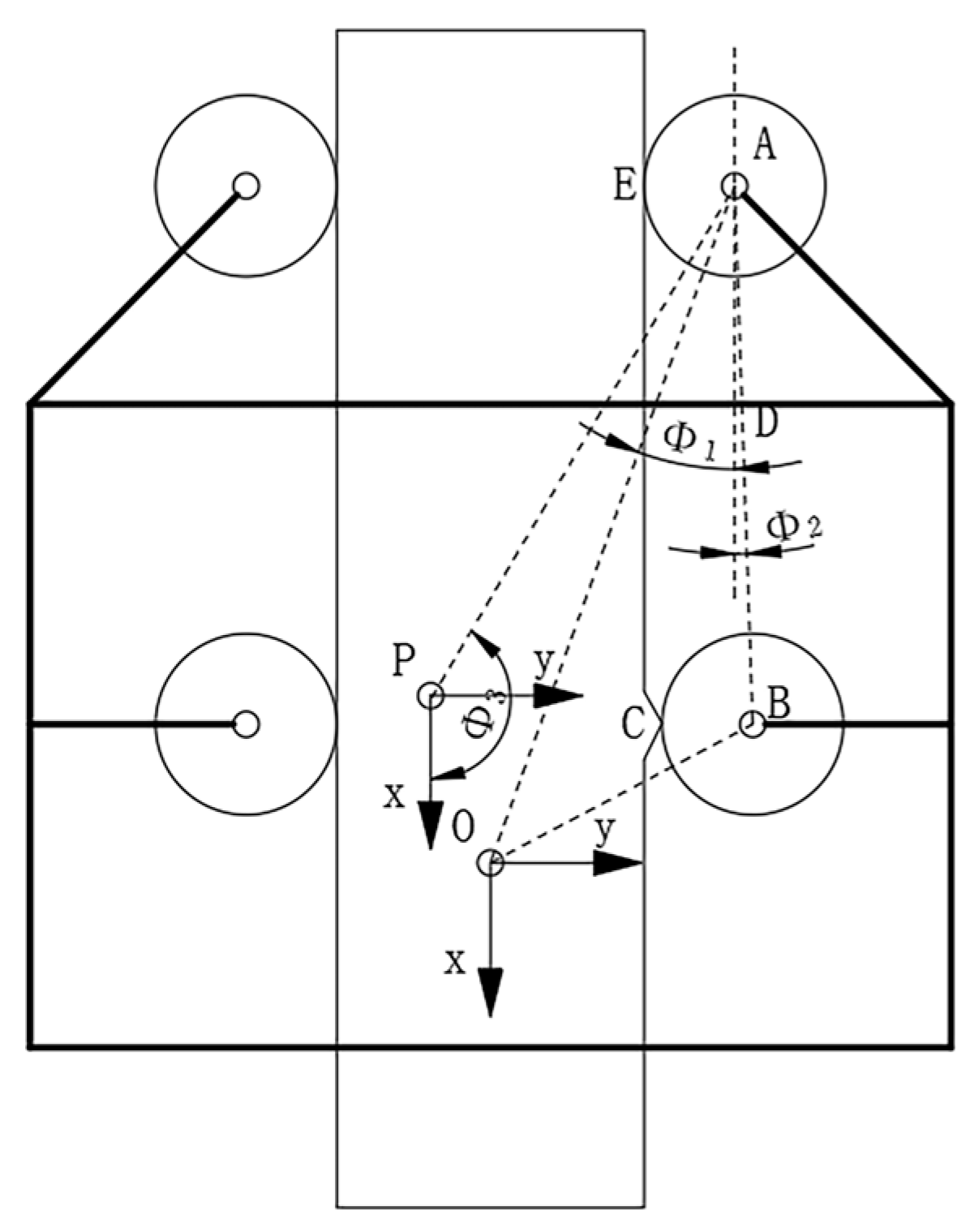
For the guide wheels, during the climbing process of the wire rope maintenance device, assuming the device moves at a constant speed and there are obstacles on the wire rope, the position model of the guide wheels of the wire rope maintenance device is simplified to a two-dimensional plane model, as shown in Figure 7.
Performing a kinematic analysis on the wire rope maintenance device, we set the center of the scraper blade as point O and established an x-y plane coordinate system. The -x axis is the direction of motion for the wire rope maintenance device, and the radius of each guide wheel is denoted as r while the radius of the wire rope is denoted as R. Setting the centers of the guide wheels on the right side as A and B respectively, we obtain the coordinates of the center point of guide wheel A is obtained:
x A = L O A cos Φ 1 y A = L O A sin Φ 1 = r + R
From Figure 7, the following vector equation is obtained:
E A + A B = E C + C B
Converting the above equation, the following is obtained:
x B = x A + L A B cos Φ 2 y B = y A + L A B sin Φ 2
Substituting the coordinates of point a, the following is obtained:
x B = L O A cos Φ 1 + L A B cos Φ 2 y B = L O A sin Φ 1 + L A B sin Φ 2
Then we can obtain the angle of deviation between the line connecting the centers of the two wheels on the right side and the axis of the wire rope is also obtained:
Φ 2 = a c r t a n y A y B L A B 2 y A y B 2
By taking the derivative of the equation, the velocity of the center point of guide wheel A is the following:
x A ˙ = Φ 1 ˙ L O A sin Φ 1 y A ˙ = Φ 1 ˙ L O A cos Φ 1
The center point of guide wheel B is obtained:
x B ˙ = Φ 1 ˙ L O A sin Φ 1 Φ 2 ˙ L A B sin Φ 2 y B ˙ = Φ 1 ˙ L O A cos Φ 1 + Φ 2 ˙ L A B cos Φ 2
By taking the derivative of the velocity of the center points of guide wheels A and B, the acceleration of the center points of guide wheels A and B is obtained:
x A ¨ = Φ 1 ¨ 2 L O A cos Φ 1 y A ¨ = Φ 1 ¨ 2 L O A sin Φ 1
By computing the derivative of the formula, the angular velocity and angular acceleration of the AB rod, as well as the acceleration of guide wheel B is obtained:
Φ 2 ˙ = y A ˙ L A B cos Φ 2
Φ 2 ¨ = y A ¨ + Φ 2 ˙ 2 L A B sin Φ 2 L A B cos Φ 2
x B ¨ = L O A sin Φ 1 L A B sin Φ 2 = x A ¨ L A B Φ 2 ¨ sin Φ 2 + Φ 2 ˙ 2 cos Φ 2 y B ¨ = 0
Assuming point P is the center of gravity of the device, the coordinates, velocity, and acceleration of point P is obtained:
x P = x A + L A P cos Φ 3 y P = y A + L A P sin Φ 3
x P ˙ = x A ˙ Φ 3 ˙ L A P sin Φ 3 y P ˙ = y A ˙ + Φ 3 ˙ L A P cos Φ 3
x P ¨ = x A ¨ Φ 3 ¨ L A P sin Φ 3 Φ 3 ˙ 2 L A P cos Φ 3 y P ¨ = y A ¨ + Φ 3 ¨ L A P cos Φ 3 Φ 3 ˙ 2 L A P sin Φ 3
The above equations constitute the kinematic analysis equations for the climbing motion of the guide wheels of the wire rope maintenance device. The relevant motion parameters of the guide wheels can be determined through these equations.

4.2. Kinematic Analysis of the Twist Wheels

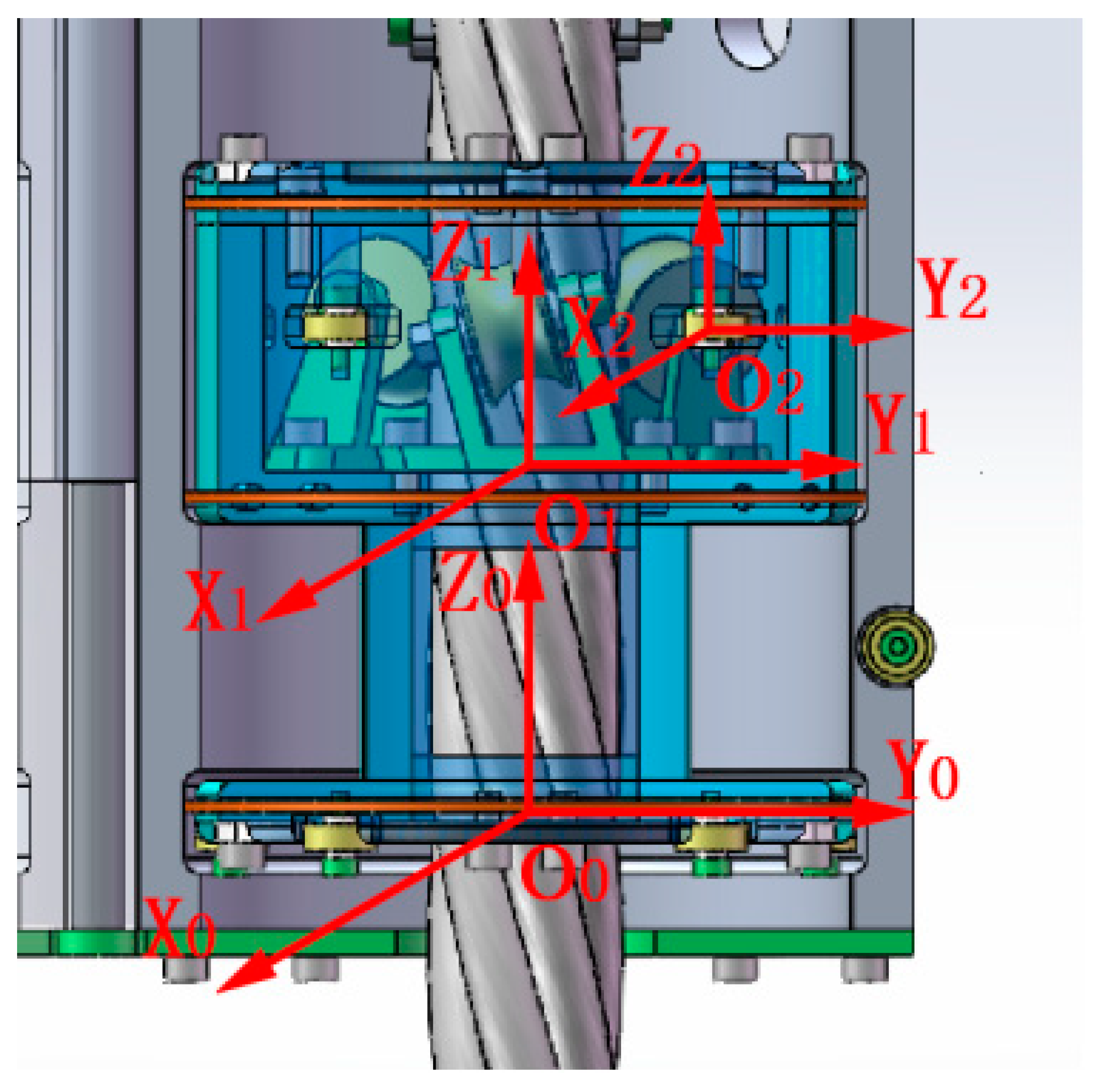
For the twist wheels, a global coordinate system O 0 was established for the wire rope maintenance device, as shown in Figure 8. The Z 0 axis is aligned with the axis of the wire rope, and the positive direction is the same as the direction of device operation. The origin is set at the center of the scraper blade O 0 . The { O 1 } represents the wheel set system composed of three twist wheels, and the origin is the intersection point of the plane formed by the centers of three twist wheels and the Z 0 axis. The representation of point O 1 on O 0 is denoted as 0,0 , Z 1 . The { O 2 } represents the coordinate system established with the center of the twist wheel as the origin.
At a certain moment during the operation of the device, the Z 0 axis is collinear with the Z 1 axis, the angle between the X 0 and X 1 axes are denoted as α , the inclination angle of the twist wheel is denoted as θ , and the distance from the center of the twist wheel to the x-y plane of O 1 is denoted as β . The relevant matrix coordinate system can be obtained as shown below.
T 1 0 = cos α sin α 0 0 sin α cos α 0 0 0 0 1 Z 1 0 0 0 1
T 2 1 = cos α 0 sin α 0 0 1 0 r + R sin α 0 cos α β 0 0 0 1
By setting the position of the contact point between the twist wheel and the wire rope in the corresponding coordinate system { O n } as f i n i = 1 ,   2 ,   3 , we can obtain the coordinates of the corresponding contact point on { O 2 }.
f i 2 = 0 r 0 T
After applying, the transformation matrix is obtained:
f i 0 = T 1 0 T 2 1 f i 2 = R sin α R cos α Z 1 + β T
In the working state, the twist wheels will be in close contact with the wire rope. At the same time, the twist wheel set can slide relative to the shell around the axis. This module will rotate together with the wire rope, working in a spiral path. When the twist wheel set rotates around the axis α ° , its trajectory projected onto the Z 0 axis of the global coordinate system is obtained:
Z 1 = R α tan θ
Substituting the above, the matrix is obtained:
f i 0 = R sin α R cos α R α tan θ + β T
The three twist wheels are evenly distributed on a circular path, with lines connecting them to the circumference forming angles of 120° each. From this, the contact point formula for each twist wheel is obtained:
f i 0 = R s i n 120 ° i 1 + α R c o s 120 ° i 1 + α R t a n 120 ° i 1 + α + β

5. Experiments

During the operation of the wire rope maintenance device, there is friction between the guide wheels and the wire rope. When there is sliding friction, it can have an impact on the working efficiency and the strength of the workpiece. Therefore, it is advisable to maintain a rolling friction state as much as possible. In this state, the moments in all directions of the moving wire rope maintenance device are balanced. The following will provide a kinetic analysis of the axial motion of the wire rope maintenance device.
A physical simulation analysis of the wire rope maintenance device was conducted in Adams, and the shell was made transparent, as shown in Figure 9. Based on the kinematic model, the relevant data changes during the climbing of the wire rope by the maintenance device can be obtained. The radius of each guide wheel is 14 mm, and the radius of each twist wheel is 15 mm. To verify the motion state of the wire rope maintenance device during climbing, relevant mechanical simulations were performed. Constraints and driving settings for the wheel set were applied in the forward kinematic simulation of the wire rope maintenance device, and a simulation motion of 9 s and 500 steps was conducted.
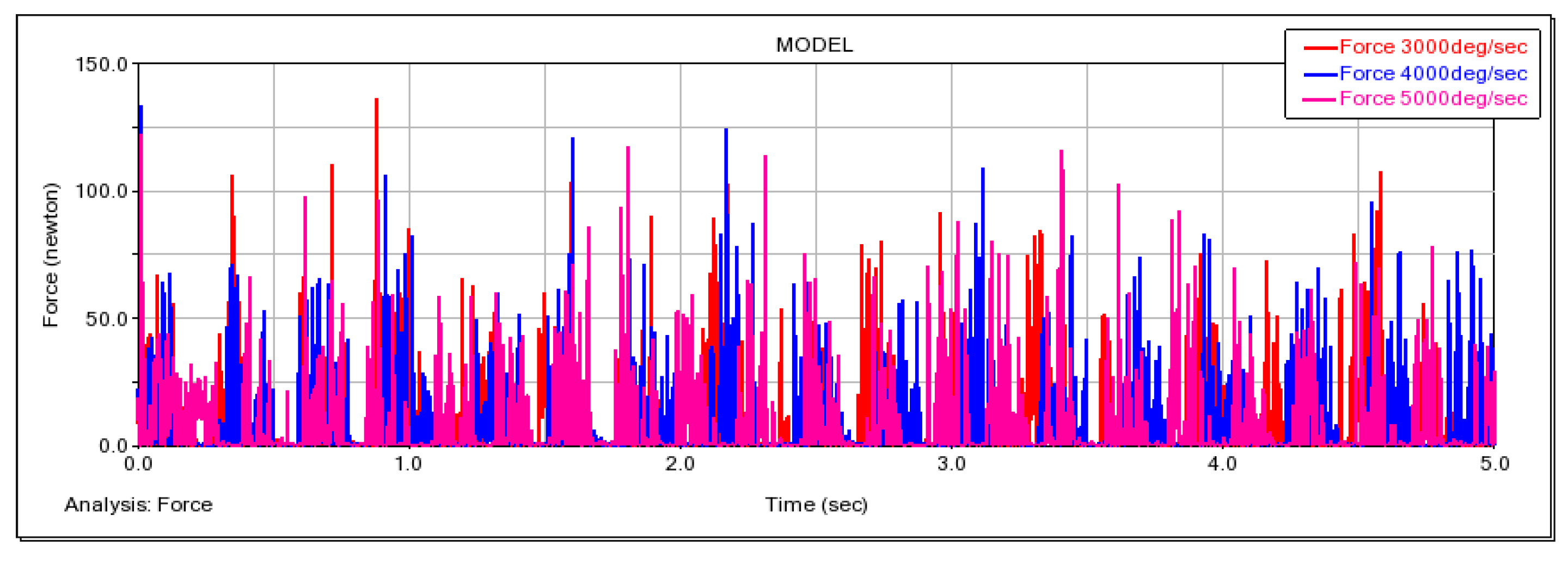
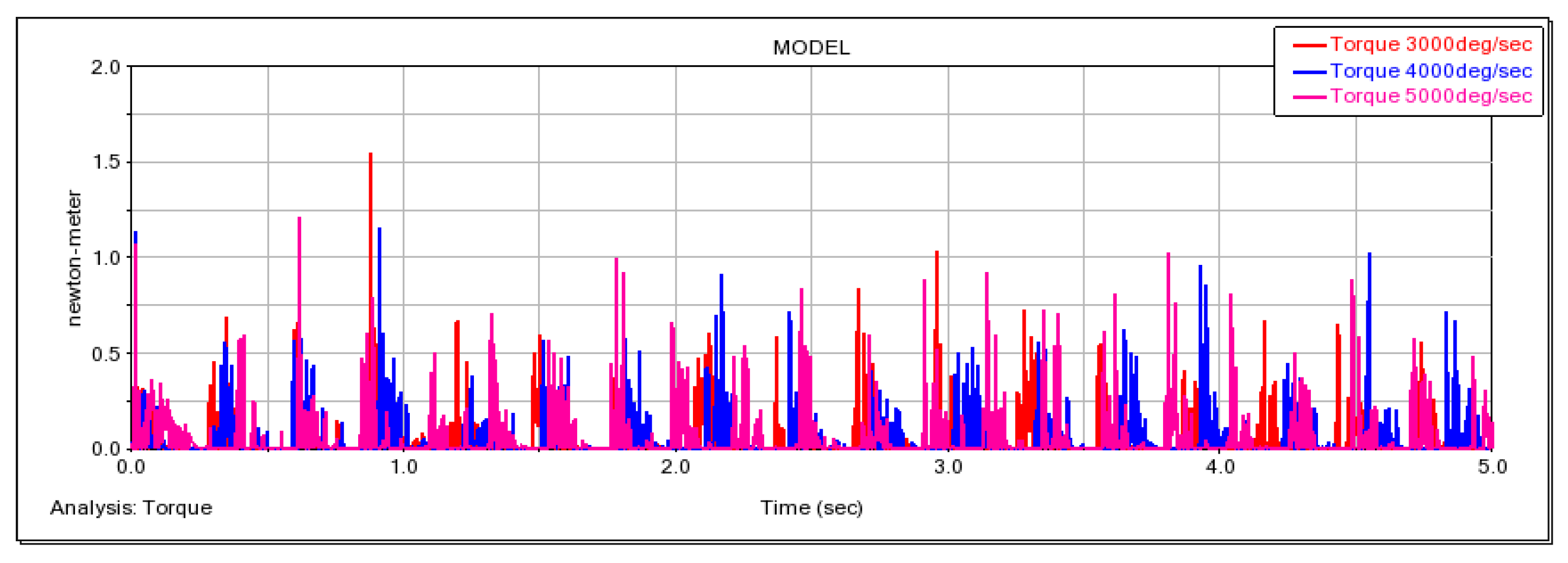
Based on the design of the wire rope maintenance device, we conducted a study on the device’s motion curve. By assigning three stable velocity states to the guide wheel, namely 3000 deg/s, 4000 deg/s, and 5000 deg/s, the wire rope maintenance device starts moving on the wire rope. At the same time, the static friction coefficient is set to 0.3 and the dynamic friction coefficient is set to 0.1. The overall motion velocity of the wire rope maintenance device, as well as the torque and traction force of the guide wheel, are obtained. The corresponding curves are shown in Figure 10, Figure 11 and Figure 12.
Due to the different positions of the guide wheel and the twist wheel, there are certain deviations in displacement, velocity, and acceleration during the operation. At the beginning, due to the presence of inertia, the torque on the guide wheel is maximum, and then it tends to stabilize. During the motion, there are obstacles on the surface of the wire rope, resulting in continuously changing motion resistance, which leads to fluctuations in the torque on the guide wheel within a certain range. The simulation results are shown in Figure 12.
At the same time, during the motion, there is also a certain range of fluctuation in the coaxiality between the axis of the wire rope maintenance device and the axis of the wire rope, but it remains relatively stable, as shown in Figure 13.
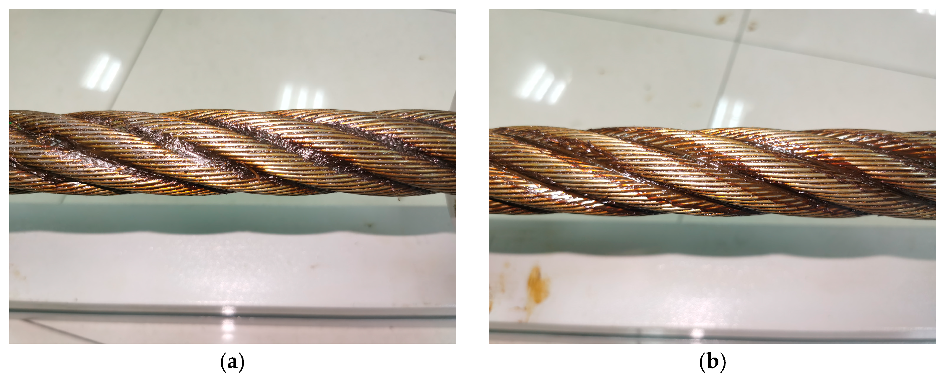
An experimental platform was set up for the wire rope maintenance device, as shown in Figure 14. Scrape tests were conducted on the waste grease on the surface of the wire rope, as illustrated in Figure 15. The experimental data obtained are shown in Table 2. The experiments demonstrated that the device could be easily pulled with a force of 150 N to scrape off the old lubricating grease from the wire rope surface.
The experimental results indicate that the device can work stably on the fixed wire rope at a speed of 0.6 m/s with a traction force of less than 150 N. Furthermore, the fluctuation between the central axis of the device and the central axis of the wire rope remains within ±0.1 mm, which is in line with expectations. These experimental findings are consistent with the results predicted by the aforementioned equations, confirming the accuracy of the theoretical derivation.

6. Conclusions and Future Work

This paper introduces a novel wire rope maintenance device, primarily composed of a heating module, a rotor module, and a housing module, capable of working stably on a fixed wire rope with a traction force of less than 150 N at a speed of 0.6 m/s. Based on the actual working environment, the motion of the rotor module of the wire rope maintenance device was modeled. By analyzing the model parameters of the wire rope maintenance device, the relevant motion parameter equations for the guide wheel and twist wheel were determined. This analysis revealed the impact of the wheel assembly’s position and the input angle on the displacement, velocity, and acceleration output of the wire rope maintenance device, providing a theoretical basis for the rapid selection of operational parameters for the wire rope maintenance robot in real working environments. Furthermore, the stability of the grease coating of the device was validated through simulations and experiments. Test results indicate that, following the operation of the device, the coaxiality of the grease formed on the wire rope surface after cleaning and lubrication remains within a range of ±0.1 mm, and the operating speed is suitable to meet the maintenance requirements of ropeway wire ropes. This device can be used not only in applications involving grease cleaning and coating, but also in scenarios related to wire rope inspection and lubrication performance testing.
In our future research endeavors, we will place a significant focus on exploring methods for detecting steel wire rope wear. These methods include: the automatic identification of surface damage on steel wire ropes through image processing techniques and pattern recognition [21]; the detection of localized faults in steel wire ropes by measuring magnetic flux using magnetic leakage detection technology [22]; the maintenance of power lines through a vision-based OGW strand detection method [23]; the implementation of multi-image stitching for partially overlapping regions in different defect images using an effective Scale-Invariant Feature Transform (SIFT) algorithm [24]; and the assessment of the stress state of steel wire ropes using ultrasonic wave methods [25].
Furthermore, we will delve into the influence of lubricating grease characteristics on steel wire rope wear, encompassing aspects such as: the exacerbation of wear on friction liners with an increase in sliding speed or load [26]; the decrease in friction, with friction levels dependent on the surface characteristics of the steel wire rope and plastic sheath, the gap between the plastic sheath and steel wire rope, and the extrusion process of the plastic sheath, as grease thickness increases [27]; a noticeable reduction in wear and friction coefficients with rising temperature [28]; the impact of lubricants on reducing damage-inducing fretting wear during the running-in phase, particularly in grease-lubricated contacts [29]; and the direct proportionality between the loss modulus of friction-enhancing lubricating grease and the friction coefficient [30].
In addition, we will explore factors influencing grease thickness applications, including: the presence of a critical rolling speed for specific lubricants and operating conditions, below which a decrease in film thickness is observable [31]; the influence of non-Newtonian properties of coating fluids on coating performance and quality [32]; viscous fluid coating thickness being contingent on liquid viscosity and deposition velocity as well as scraper length, stiffness, shape, and constraints, with maximum deposition thickness occurring when the scraper’s tip is tangent to the solid [33]; the linear increase in boundary yield stress with rising lubricant viscosity and sliding speed [34]; the role of internal stress fields within the reservoir in determining coating thickness [35]; and the increase in lubricating grease film thickness with rising rolling speed and its tendency to level off with balanced thickening agent usage in the contact zone [36].
Specifically, we will investigate the effects of different application speeds, oil chamber pressures, grease viscosities, and scraper shapes on grease thickness distribution. Through systematic experimentation and analysis, our aim is to unveil the behavior of lubricating grease under specific conditions, providing a deeper understanding of the extent to which different parameters affect lubrication effectiveness. This research will contribute to optimizing the design and performance of lubrication systems, enhancing the efficiency and lifespan of steel wire ropes. We anticipate that this study will offer robust support for engineering practices and technological innovations in related fields, promoting the development and application of lubrication science.

Author Contributions

Conceptualization, W.W. and H.Y.; methodology, W.W. and H.Y.; software, H.Y. and Y.C.; validation, J.C. and W.Z.; formal analysis, W.W.; investigation, X.H.; resources, W.W.; data curation, H.Y.; writing—original draft preparation, H.Y.; writing—review and editing, W.W.; visualization, Y.C.; supervision, W.W.; project administration, W.W. All authors have read and agreed to the published version of the manuscript.

Funding

This research was funded by National Nature Science Foundation of China grant number 61976083.

Data Availability Statement

No new data were created or analyzed in this study. Data sharing is not applicable to this article.

Conflicts of Interest

The authors declare no conflict of interest.

Abbreviations

A / B Two points of contact between the guide wheel and the wire rope M Total mass of the device
N 11 Normal reaction on the upper side of the right guide wheel’s surface N 12 Normal reaction under the right guide wheel’s surface
N 21 Normal reaction on the upper side of the left guide wheel’s surface N 22 Normal reaction under the left guide wheel’s surface
T 1 Tangential reaction of the wire rope to the guide wheel P 1 / P 2 Vertical force at the point of contact between the guide wheel and the wire rope
Q 1 / Q 2 Transverse force at the point of contact between the guide wheel and the wire rope α Angle between the normal reaction and the vertical direction
μ Friction coefficient between the guide wheel and wire rope’s surface L 1 Distance from the center of mass to the vertical line of the wire rope
L 2 Vertical distance between the contact point of the guide wheel and the center of the wire rope L 3 Vertical distance between the contact point of the guide wheel, wire rope, and the wire rope’s center of mass
a Acceleration of transverse vibration of the wire rope g Acceleration of gravity
N i 1 Twist the normal force to the upper side of the wheel’s surface(i = 3, 4, 5) N i 2 Apply the normal reaction to the lower side of the wheel’s surface(i = 3, 4, 5)
N 4 Normal force on the surface of the twist wheel f 4 Friction force on the surface of the twist wheel
μ 1 Friction coefficient of the twist wheel’s surface F 4 Supporting force of the twist wheel’s fixed seat against the twist wheel
F 5 Pressure between the underside of the rotor and the housing r Twist wheel radius
F 6 Resistance of lubricating oil to the movement of the twist wheel f 5 Friction between the bottom of the rotor and the housing
f 6 Friction between the side of the rotor and the inside of the housing μ Coefficient of sliding friction between the rotor surface and housing
F 6 a Resistance between the lower surface of the rotor and the grease F 6 b Resistance between the upper surface of the rotor and the grease
F 6 Resistance difference between the upper and lower surfaces of the rotor p Fluid pressure
ρ Grease density r Radius of the guide wheel
R Radius of wire rope Φ 1 Angle between the line between the center of the guide wheel and the center of the scraper and the vertical line (acute Angle)
Φ 2 Deviation angle (acute angle) of the unilateral two-wheel centerline relative to the wire rope axis Φ 3 Angle between guide wheel center A and the scraper center and vertical line (obtuse Angle)
x A ˙ / y A ˙ Center point speed of guide wheel A x B ˙ / y B ˙ Center speed of guide wheel B
x A ¨ / y A ¨ Center point acceleration of guide wheel A x B ¨ / y B ¨ Center point acceleration of guide wheel B
Φ 2 ˙ Angular velocity of bar AB Φ 2 ¨ Angular acceleration of the AB bar
x P / y P Center of gravity coordinates of the device x P ˙ / y P ˙ Center of gravity velocity of device
x P ¨ / y P ¨ Acceleration of the center of gravity of the device α The angle between the center axis X 0 of the scraper and the center axis X 1 of the twist wheel
θ Twist wheel inclination β Distance between the center of the twist wheel and the x-y plane of the twist wheel support
f i j Point of contact between the twist wheel and the wire rope (j = 0, 1, 2, i = 1, 2, 3) V a Speed of the guide wheel in normal working condition
V b Speed of the twist wheel in normal working condition C Pitch of the wire rope

References

  1. Patil, M.B.P.; Chaudhari, H.D. Wire rope lubrication system for harbor mobile cranes. Int. J. Eng. Sci. Res. Technol. 2018, 7, 227–231. [Google Scholar]
  2. Zheng, M.; Li, Y.; Li, J.; Yuan, K. Structure design and kinematical analysis of a new type cable climbing robot. In Proceedings of the 2010 Second International Conference on Intelligent Human-Machine Systems and Cybernetics, Nanjing, China, 26–28 August 2010; Volume 1, pp. 284–287. [Google Scholar]
  3. Kim, H.M.; Cho, K.H.; Jin, Y.H.; Liu, F.; Choi, H.R. Development of a climbing robot for inspection of bridge cable. J. Korea Robot. Soc. 2012, 7, 83–91. [Google Scholar] [CrossRef]
  4. Xi, F.; Jiang, Q. Dynamic obstacle-surmounting analysis of a bilateral-wheeled cable-climbing robot for cable-stayed bridges. Ind. Robot-Int. J. Robot. Res. Appl. 2019, 46, 431–443. [Google Scholar] [CrossRef]
  5. dos Santos, C.H.F.; Abdali, M.H.; Martins, D.; Alexandre, C.B.A. Geometrical motion planning for cable-climbing robots applied to distribution power lines inspection. Int. J. Syst. Sci. 2021, 52, 1646–1663. [Google Scholar] [CrossRef]
  6. Jiang, W.; Ye, G.C.; Zou, D.H.; Yan, Y. Mechanism configuration and innovation control system design for power cable line mobile maintenance robot. Robotica 2021, 39, 1251–1263. [Google Scholar] [CrossRef]
  7. Wang, Z.; He, B.; Zhou, Y.; Liu, K.; Zhang, C. Design and implementation of a cable inspection robot for cable-stayed bridges. Robotica 2021, 39, 1417–1433. [Google Scholar] [CrossRef]
  8. Fang, G.; Cheng, J. Design and implementation of a wire rope climbing robot for sluices. Machines 2022, 10, 1000. [Google Scholar] [CrossRef]
  9. Chen, G.; Yang, H.; Cao, H.; Ji, S.; Zeng, X.; Wang, Q. Design of an embracing-type climbing robot for variation diameter rod. Ind. Robot-Int. J. Robot. Res. Appl. 2019, 46, 56–72. [Google Scholar] [CrossRef]
  10. Li, P.; Duan, X.; Sun, G.; Li, X.; Zhou, Y.; Liu, Y. Design and control of a climbing robot for inspection of high mast lighting. Assem. Autom. 2019, 39, 77–85. [Google Scholar] [CrossRef]
  11. Kim, H.M.; Cho, K.H.; Liu, F.; Choi, H. Development of cable climbing robotic system for inspection of suspension bridge. In Proceedings of the 28th International Symposium on Automation and Robotics in Construction, ISARC, Seoul, Republic of Korea, 29 June–2 July 2011. [Google Scholar]
  12. Kim, H.M.; Cho, K.H.; Jin, Y.H.; Liu, F.; Koo, J.C.; Choi, H.R. Development of cable climbing robot for maintenance of suspension bridges. In Proceedings of the 2012 IEEE International Conference on Automation Science and Engineering (CASE), Seoul, Republic of Korea, 20–24 August 2012; pp. 606–611. [Google Scholar] [CrossRef]
  13. Cho, K.H.; Jin, Y.H.; Kim, H.M.; Moon, H.; Choi, H.R. Caterpillar-based cable climbing robot for inspection of suspension bridge hanger rope. In Proceedings of the Automation Science and Engineering (CASE), Madison, WI, USA, 17–20 August 2013. [Google Scholar]
  14. Cho, K.H.; Kim, H.M.; Jin, Y.H.; Liu, F. Inspection robot for hanger cable of suspension bridge: Mechanism design and analysis. IEEE/ASME Trans. Mechatron. 2013, 18, 1665–1674. [Google Scholar] [CrossRef]
  15. Cho, K.H.; Jin, Y.H.; Kim, H.M.; Moon, H.; Koo, J.C.; Choi, H.R. Multifunctional robotic crawler for inspection of suspension bridge hanger cables: Mechanism design and performance validation. IEEE/ASME Trans. Mechatron. 2017, 22, 236–246. [Google Scholar] [CrossRef]
  16. Xu, F.; Wang, X.; Wang, L. Cable inspection robot for cable-stayed bridges: Design, analysis, and application. J. Field Robot. 2011, 28, 441–459. [Google Scholar] [CrossRef]
  17. Xu, F.; Hu, J.; Wang, X.; Jiang, G. Helix cable-detecting robot for cable-stayed bridge: Design and analysis. Int. J. Robot. Autom. 2014, 29, 406–414. [Google Scholar] [CrossRef]
  18. Xu, F.; Hu, J.L.; Jiang, G. The obstacle-negotiation capability of rod-climbing robots and the improved mechanism design. J. Mech. Sci. Technol. 2015, 29, 2975–2986. [Google Scholar] [CrossRef]
  19. Xu, F.; Shen, J.; Jiang, G. Kinematic and dynamic analysis of a cable-climbing robot. Int. J. Adv. Robot. Syst. 2015, 12, 99. [Google Scholar] [CrossRef]
  20. Xu, F.; Jiang, Q.; Lv, F.; Wu, M.; Zhang, L. The dynamic coupling analysis for all-wheel-drive climbing robot based on safety recovery mechanism model. Appl. Sci. 2018, 8, 2123. [Google Scholar] [CrossRef]
  21. Ho, H.-N.; Kim, K.-D.; Park, Y.-S.; Lee, J.-J. An efficient image-based damage detection for cable surface in cable-stayed bridges. Ndt. E Int. 2013, 58, 18–23. [Google Scholar] [CrossRef]
  22. Park, S.; Kim, J.-W.; Lee, C.; Lee, J.-J. Magnetic flux leakage sensing-based steel cable nde technique. Shock Vib. 2014, 2014, 929341. [Google Scholar] [CrossRef]
  23. Song, Y.; Wang, H.; Zhang, J. A vision-based broken strand detection method for a power-line maintenance robot. IEEE Trans. Power Deliv. 2014, 29, 2154–2161. [Google Scholar] [CrossRef]
  24. Li, X.; Gao, C.; Guo, Y.; He, F.; Shao, Y. Cable surface damage detection in cable-stayed bridges using optical techniques and image mosaicking. Opt. Laser Technol. 2019, 110, 36–43. [Google Scholar] [CrossRef]
  25. Ji, Q.; Jian-Bin, L.; Fan-Rui, L.; Jian-Ting, Z.; Xu, W. Stress evaluation in seven-wire strands based on singular value feature of ultrasonic guided waves. Struct. Health Monit. 2022, 21, 518–533. [Google Scholar] [CrossRef]
  26. Ma, W.; Zhu, Z.C.; Xu, L.; Chen, G.A. Sliding friction and wear properties of friction linings with friction-promoting grease applied. Proc. Inst. Mech. Eng. Part J J. Eng. Tribol. 2014, 228, 595–607. [Google Scholar] [CrossRef]
  27. Dundu, M.; Ward, M. The effects of grease and tendon mass variances on the coefficient of friction in unbonded post-tensioning tendons. J. S. Afr. Inst. Civ. Eng. 2016, 58, 62–65. [Google Scholar] [CrossRef]
  28. Feng, C.; Zhang, D.; Chen, K.; Guo, Y. Study on viscoelastic friction and wear between friction linings and wire rope. Int. J. Mech. Sci. 2018, 142, 140–152. [Google Scholar] [CrossRef]
  29. Dyson, C.J.; Chittenden, R.J.; Priest, M.; Fox, M.F.; Hopkins, W.A. Representative tribometer testing of wire rope fretting contacts: The effect of lubrication on fretting wear. Tribol. Trans. 2020, 63, 557–574. [Google Scholar] [CrossRef]
  30. Feng, C.; Zhang, D.; Grecov, D.; Chen, K. Effect of rheological properties of friction-enhancing greases on the friction between friction lining and wire rope. Tribol. Int. 2020, 144, 106143. [Google Scholar] [CrossRef]
  31. Kupka, I.; Hartl, M.; Lika, M. Thin lubricating films behaviour at very high contact pressure. Tribol. Int. 2006, 39, 1726–1731. [Google Scholar] [CrossRef]
  32. Takeaki, T. Coating flows of power-law non-newtonian fluids in slot coating. Nihon Reoroji Gakkaishi 2011, 38, 223–230. [Google Scholar]
  33. Seiwert, J.; Quere, D.; Clanet, C. Flexible scraping of viscous fluids. J. Fluid Mech. 2013, 715, 424–435. [Google Scholar] [CrossRef]
  34. Guo, L.; Wong, P.L.; Guo, F. Effects of viscosity and sliding speed on boundary slippage in thin film hydrodynamic lubrication. Tribol. Int. 2017, 107, 85–93. [Google Scholar] [CrossRef]
  35. Smit, W.J.; Kusina, C.; Joanny, J.-F.; Colin, A. Stress field inside the bath determines dip coating with yield-stress fluids in cylindrical geometry. Phys. Rev. Lett. 2019, 123, 148002. [Google Scholar] [CrossRef] [PubMed]
  36. Zhang, Z.; Wang, Y.; Lin, J.; Wang, D. Study on factors influencing film formation of grease and calculation model for grease film thickness. Greases 2022, 10, 123. [Google Scholar] [CrossRef]
Figure 1. The lubricant coating on the wire rope’s surface. (a) The lubricant coating formed by applying lubricant using existing products and (b) the lubricant coating formed by applying lubricant along the strand’s twist direction.
Actuators 12 00392 g001
Figure 2. Overall structure of the wire rope maintenance device.
Actuators 12 00392 g002
Figure 3. Structure of the housing module.
Actuators 12 00392 g003
Figure 4. Structure of the rotor module.
Actuators 12 00392 g004
Figure 5. The force analysis of guide wheels. (a) The critical state of the rope maintenance device disengagement and (b) guide wheels contact force analysis.
Actuators 12 00392 g005
Figure 6. The force analysis of the twist wheels. (a) Twist wheel climbing model and (b) force analysis of the twist wheels.
Actuators 12 00392 g006
Figure 7. Guide wheels obstacle climbing model.
Actuators 12 00392 g007
Figure 8. Climbing diagram of wire rope maintenance device.
Actuators 12 00392 g008
Figure 9. The forward motion simulation model in Adams.
Actuators 12 00392 g009
Figure 10. Simulation of the overall motion velocity of the wire rope maintenance device.
Actuators 12 00392 g010
Figure 11. Simulation of the torque on the guide wheel of the wire rope maintenance device.
Actuators 12 00392 g011
Figure 12. Simulation of the traction force on the guide wheel of the wire rope maintenance device.
Actuators 12 00392 g012
Figure 13. Fluctuation in the relative position between the axis of the device and the axis of the steel wire.
Actuators 12 00392 g013
Figure 14. Maintenance device and experimental platform. (a) Before installing the housing module, and (b) the traction test of the wire rope maintenance device.
Actuators 12 00392 g014
Figure 15. Scraping test for waste grease on the surface of wire rope. (a) Before scraping and (b) after scraping.
Actuators 12 00392 g015
Table 1. Basic parameters of wire rope maintenance device.
Weight3 kg
Radius of the guide wheels14 mm
Radius of the guide wheels15 mm
Radius of the wire rope20 mm
Pitch of the wire rope300 mm
Twist wheel inclination15°
Table 2. Parameters for Wire Rope Maintenance Device Traction Experiment.
Startup SpeedTraction Force
0.4 m/s51.3 N
0.6 m/s107.7 N
0.8 m/s147.3 N
Disclaimer/Publisher’s Note: The statements, opinions and data contained in all publications are solely those of the individual author(s) and contributor(s) and not of MDPI and/or the editor(s). MDPI and/or the editor(s) disclaim responsibility for any injury to people or property resulting from any ideas, methods, instructions or products referred to in the content.