Abstract
This research project investigated the additive manufacturing of pneumatic actuators based on the principle of droplet dosing using an Arburg Freeformer 300-3X 3D printer. The developed structure consists of a porous inner filling and a dense, airtight chamber. By selectively varying the filling densities of the porous inner filling, different membrane deflections of the actuator were achieved. By linking the actuators, a pneumatic network actuator was developed that could be used in endorobotics. To describe the membrane deflection of an additively manufactured pneumatic actuator, a mathematical model was developed that takes into account the influence of additive manufacturing and porous filling. Using a dedicated test rig, the predicted behavior of the pneumatic actuators was shown to be qualitatively consistent. In addition, a pneumatic network actuator (PneuNet) with a diameter of 17 mm and a height of 76 mm, consisting of nine chambers with different filling densities, could be bent through 82° under a pressure of 8 bar. Our study shows that the variation of filling densities during production leads to different membrane deflections. The mathematical model developed provides satisfactory predictions, although the influence of additive manufacturing needs to be determined experimentally. Post-processing is still a necessary step to realize the full bending potential of these actuators, although challenges regarding air-tightness remain. Future research approaches include studying the deflection behavior of the chambers in multiple directions, investigating alternative materials, and optimizing the printing process to improve mechanical properties and reliability.
1. Introduction
A pneumatic actuator (PA) is a device that converts energy stored in compressed air into mechanical motion. PA can be used in a wide range of applications such as industrial automation, robotics, and transportation. PA are also favored in the field of soft robotics because of their comparatively simple production and light weight [1]. PA systems are particularly well-suited for endorobots due to their capability to interact with soft tissues, making them an ideal choice for applications in the field of medical soft robotics. Over the past years, additive manufacturing of medical devices and personalized medicine have become increasingly important [2,3]. This enables the development of PA with greater design freedom and the possibility of realizing complex geometries. In addition, additive manufacturing can automate production and reduce time-consuming activities such as post-processing or component assembly [4].
Pneumatic network actuators, also known as PneuNets, can generate uniform bending motion along their interconnected pneumatic chambers. The walls of the chambers perpendicular to the longitudinal axis are thinner than those parallel to the longitudinal axis. When compressed air is applied to these chambers, they expand along the path of least resistance, resulting in a larger deflection w. To prevent axial expansion, a flexible spine-like confining structure connects the chambers and accommodates the inner channels [4,5]. This design ensures that PneuNet undergoes bending deformation around this structure, rather than stretching (Figure 1).
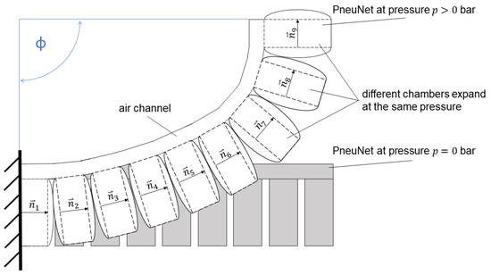
Figure 1.
Bending of a 9-chamber PneuNet with non-constant bending radius at the same pressure p to obtain a total bending angle . The individual chambers expand differently at the same pressure, resulting in a different normal vector of the chamber.
The internal pressure in all chambers remains constant, ensuring synchronized expansion throughout the PneuNets for uniform bending movement. In addition to uniform bending motion, PneuNets are capable of a wide range of motion patterns [6]. Previous studies have successfully demonstrated classical bending motion in a vertical plane [4,7]. Simultaneously, Liu et al. adopted an approach using two interconnected chamber systems to generate bending deformations in two vertical planes [6]. In addition, the combination of bending and torsion was investigated by introducing a chamber angle of 90° with respect to the longitudinal axis of PneuNets [8,9]. Mosadegh et al. assessed the geometric requirements for higher activation rates [5]. To mimic the bending behavior of a human finger, segmented PneuNets were used [10]. These innovative motion patterns were achieved through strategic changes in the geometric structure of PneuNet [4,11].
The development and manufacture of PneuNets require considerable time and effort. Typically, actuators are manufactured from two cast parts made of silicone or thermoplastic polyurethane (TPU) and must then be sealed airtight, for example, by laser welding. The introduction of additive manufacturing could reduce the production costs of PneuNets, while allowing for faster customization. In addition, additive manufacturing would enable the realization of more complex geometries for PneuNets, which would not be readily achievable with conventional manufacturing methods. This could encourage the development of more precise and powerful PneuNets that are versatile in their motion patterns and applications. Another key advantage of additive manufacturing is its ability to selectively create nonuniform bending deformations. However, it is apparent that the implementation of a PA using additive manufacturing involves some challenges, such as creating an airtight structure [4] and fabricating a mechanically heterogeneous structure [1]. Mastering these challenges requires a high degree of control over the manufacturing processes.
This research focuses on the development of a PneuNet with individual motion patterns that can be additively manufactured. This study follows a three-step approach: First, the realization of a printable airtight chamber is investigated. The goal is to design a chamber that can be manufactured using 3D printing techniques while maintaining a high level of airtightness (up to 8 bar) to ensure reliable actuation. In the second phase, the operation of a single PA is characterized by the variation of the filling density of the chamber. The focus was on adjusting the expansion of the actuator to a given pressure. This allows for the customization of motion patterns and opens new possibilities for precise and customized actuators. Finally, in the Section 3, a PneuNet with non-uniform bending motion is printed. By combining the previously developed chamber and material concepts, it is possible to realize targeted and complex bending deformations in PneuNet.
2. Materials and Methods
A Freeformer 300-3X (Arburg GmbH & Co. KG, Lossburg, Germany) was used to produce the actuators (Figure 2). This 3D printer allows the simultaneous processing of three different thermoplastic materials and operates according to the droplet dispersion principle [12]. Similar to an injection molding machine, plastic granules are melted in an extruder screw and forwarded to the ejection unit. The droplets are generated by a high frequency piezoelectric nozzle shutter. The droplets are positioned on the moving build platform in the heated assembly space. This process allows the mechanical properties of a material to be tailored to specific requirements. Two key parameters for the realization of a printable PA are the form factor and filling density .
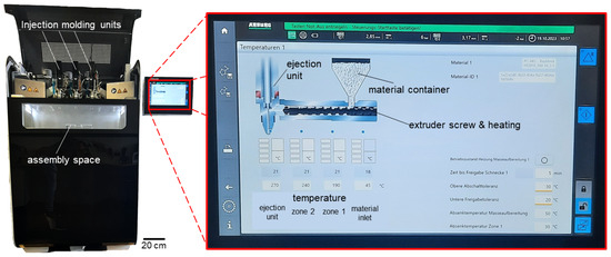
Figure 2.
The Freeformer 300-3X has three injection units. As shown on the display, the plastic granules are melted by an extruder screw similar to an injection molding machine. The melted granules is forwarded to the ejection unit where droplets are generated by a piezoelectric high frequency nozzle shutter. The droplets are additively deposited onto the build platform in the heated assembly space.
is defined as the ratio of the droplet width to the droplet height (Figure 3) and depends on the dosing and temperature settings of the Freeformer and material used. When different materials are used in the printing process, the droplet height should be approximately the same for all materials to achieve a satisfactory print result. This ensures uniform material processing and adhesion. The materials Desmopan 9385A (Covestro AG, Leverkusen, Germany) with a Young’s modulus at 20 °C according to the manufacturer’s data sheet and Bayblend FR3010 (Covestro AG) were used. Armat11 (Arburg GmbH & Co. KG, Loßburg, Germany) was used as a water-soluble support material.

Figure 3.
Coalescence between two droplets with a form factor depending on the droplet width and droplet height ; (a) contact between the surfaces; (b) merging at the contact surface; (c) molecular diffusion and bonding across the interface. The more the droplets overlap, the greater the adhesion.
describes the amount of material or droplets used to fill a part. It can vary from 0% to 100%. Changes to can affect and cause overfilling of the part. This property created an airtight structure that proved advantageous for the desired applications. In addition, coalescence (Figure 3) between the droplets plays an important role. Depending on the strength of the coalescence, the bond between the droplets can be referred to as an adhesive force [13].
The adhesion force is lowest when there is only contact between the surfaces. Merging at the contact surfaces leads to a higher adhesion force, and if molecular diffusion and interlocking occurs at the interfaces, this increases the adhesion force.
By understanding and selectively controlling these parameters (Table 1) it is possible to additively manufacture actuators. In the following sections, the effects of these factors on the material behavior and performance of the manufactured PAs are examined in more detail. Figure 4 shows a print layer for different for a .

Table 1.
The processing parameters form factor , filling density and temperature distribution within the extruder screw and ejection unit of the Freeformer of the materials used.

Figure 4.
A printing layer for different fill densities (15% to 40%) with a form factor . The drop chains are arranged at a 45° angle within a square. The next print layer would deposit the drop chains at a 90° angle to the previous drop chain, forming the porous fill. Depending on the fill densities , the distance between the droplet chains and thus the porous filling can be adjusted.
2.1. Airtight Chamber
An essential part of this study was the fabrication of an airtight chamber using Desmopan as the main material. A test chamber was constructed with three main components: an outer shell that acted as an airtight barrier, an inner filling () that performed specific functions, and a connection for the supply of compressed air. The outer shell had a wall thickness of 0.8 mm. To assess air tightness, the chamber was pressurized to 8 bar and held under water. The appearance of air bubbles would indicate a leak.
2.2. Porous Filling
In this section, we focus on the effects of the porous filling on a PA (Figure 5). For this purpose, of 15, 20, 25, 30, 35, and 40% were investigated. The main objective was to analyze the influence of on the transverse deflection w of a PA (Figure 6).
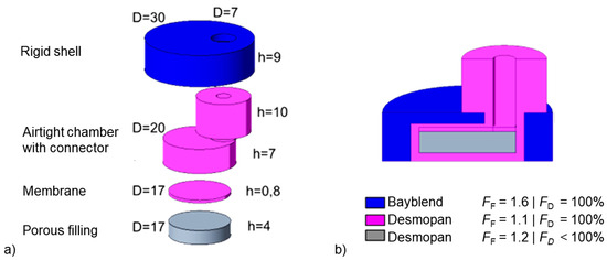
Figure 5.
Exploded view (a) of an airtight PA with a porous filling in a rigid shell. The porous filling is inside the airtight chamber (b), which allows for additive manufacturing. The individual parts with their respective diameters D and heights h are identified by their color, what material they are made of and what form factor and filling density are assigned to them.
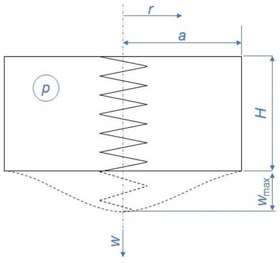
Figure 6.
The sketch shows an equivalent representation of the filling and deflection w with increasing differential pressure p in the chamber. The geometry is cylindrical with height H and radius .
The mathematical description of the system is based on the behavior of a circular membrane under differential pressure and follows a strain-energy/virtual deflection approach [14]. Such an approach was also used for the description of similar PA [10]. From Figure 6, the transverse deflection
and radial deflection
under load are initially assumed, where and are constants. Further, the membrane is subjected to radial
and transverse strains
once it deforms. This deformation of the membrane is associated with strain energy
where E is Young’s modulus, h is membrane thickness, and v is Poisson’s ratio. Since the porous filling also expands, the associated strain energy
is assumed according to Hooke’s law for spring systems. This is described approximately by the mean deflection. The spring/filling constant
describing the filling is approximately interpreted as a linear model similar to a tension rod. The circular fill area is approximated by the fill densities . The adhesive force of the printed droplets from the Freeformer influences how strongly individual droplets and the printed layers bond to each other, thus influencing the spring/fill constant. This influence due to the specific additive manufacturing is represented with the factor and was determined by iterative recalculation of the experimental data. The total strain energy
is the sum of membrane and porous fill strain energy (Equations (5) and (6)). Using the constraints
and substitutes Equations (1)–(8) it is possible to determine the constants
Next, the change in work performed by the differential pressure acting through a virtual displacement must be equal to the change in deformation energy associated with the virtual displacement:
There is no explicit solution for given by Equation (11). Therefore, Equation (11) was set to zero and solved numerically:
The nonlinear Equation (12) was solved using the MATLAB trust-region-dogleg algorithm (The MathWorks, Inc., Natrick, MA, USA) implemented in the fsolve function.
An experiment was performed to validate the mathematical description and investigate the relationship between and deflection w. The test rig is shown in Figure 7.
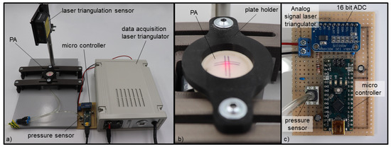
Figure 7.
Measurement setup (a) for investigating the pressure-deformation behavior of a pneumatic actuator (PA). The PA is attached to a plate holder (b). A laser triangulator is mounted vertically above and axially aligned with the PA and sends the measurement data as an analog signal to the microcontroller with a 16-bit ADC (c), which also measures the pressure.
The maximum deflection, , was measured using a laser triangulation sensor (HL-G112-S-J, Panasonic, Kadoma, Japan) at pressures of 0 to 8 bar on the actuator. The applied pressure was recorded using a basic board-mounted pressure sensor (ABPDANN010BGAA5, Honeywell International Inc., Charlotte, NC, USA). The sensor signals were recorded with a microcontroller (ArduinoNano, Arduino S.r.l., Monza, Italy), and then evaluated using MATLAB. It was assumed that the deflection changes accordingly by varying at the same pressure (see Equation (12)). Three actuators were manufactured for each , and ten measurements were performed for each actuator. Since Desmopan is a viscoelastic material, a waiting period of 3 min (relaxation of the material) was kept after the pressure setting before the membrane deflection was measured. The PA were mounted in a rigid PC-ABS shell such that only axial deflection could occur under a pressure load. The mark indicates the center of the membrane and thus the highest point of deflection .
The results of these tests allowed for a quantitative investigation of the effects of different on PA. Conclusions regarding the stiffness of the filling were drawn from a comparison of the measured strain heights at different , and the correction factor for additive manufacturing was determined. This makes it possible to gain a comprehensive understanding of how an actuator with a porous filling works.
2.3. Pneumatic Network Actuator (PneuNet)
The geometry was designed using Creo Parametric 5.0 (PTC Inc., Boston, MA, USA). Individual airtight chambers were combined to form a PneuNet (Figure 8). Nine chambers were stacked and laterally connected by an air channel (). The air channel was also the backbone of the actuator. This allowed the actuator to bend only in one direction in the Eyz-plane, and the same pressure was applied to all chambers via the air channel. The chambers were filled with different densities to reduce the distal radius of curvature. Thus, chambers 1 and 2 were designed with a 40% filling density, and chambers 3 and 4 were designed with a 35% filling density, resulting in a larger radius of curvature under a compressive loading. To achieve a smaller radius of curvature at the distal end, chambers 6 and 7, and chambers 8 and 9, were designed with filling densities of 30% and 15%, respectively. To ensure that the chamber interstices of the PneuNet were printable, they were constructed with Desmopan filling (). The actuator was firmly integrated into a base plate of PC-ABS (Bayblend FR3010), through which the compressed air was also connected.
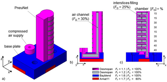
Figure 8.
System design of the PneuNet with nine chambers in isometric view (a), sectional view of the air channel (b) and sectional view of the chambers (c). The color indicates what material the parts are made of and what form factor and filling density they have. The interstices between the chambers had to be filled so that the PneuNet could be manufactured additively (build direction in positive z-axis).
As the chambers of the PneuNet (Figure 8) expand under pressure, the total bending angle
of the PA can be described as a function of the first chamber and the last chamber (Figure 1). Evaluation included a graphical analysis using ImageJ 1.54d software (National Institute of Health, MD, USA). The measurement process included both untreated samples and those that underwent post-processing. In the post-processing phase, the chamber interstices were carefully incised with a scalpel to increase the total bending angle.
3. Results
3.1. Airtight Chamber
The test chamber withstands a pressure of 8 bar without air bubbles appearing under water. Figure 9 shows the cross-section of a test chamber. The enlargement shows that the chamber was compactly fused and airtight. The chamber top above the filling was less homogeneous and less transparent than the sidewalls. An airtight structure can be achieved by selectively overfilling of this area.
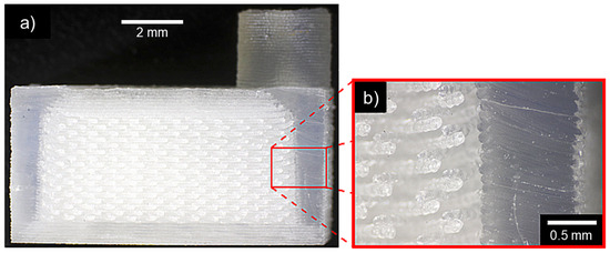
Figure 9.
Cross-section of a manually cut test chamber (a) and contour of the outer shell (b) for airtightness testing. The outer shell has a compact structure and the interior of the chamber is formed by a porous filling.
3.2. Porous Filling
Airtight chambers with different filling densities ( = 15% to 40% in steps of 5%) were printed (Figure 10). The expansions under compressive loading for different filling densities are shown in Figure 11 with for the mathematical model. With increasing pressure, the expansion also increased. The lower the filling level, the greater the expansion. Thus, at a pressure of 2 bar, the expansion was reduced by 35% if a filling ratio of 40% was used instead of 15%. The difference in expansion increased to 55% when the pressure was increased to 8 bar. It can also be seen that the difference in expansion between a filling ratio of 15% and 20% and between a filling ratio of 25% and 30% is quite small (<5% on average).

Figure 10.
Manufactured pneumatic actuator PA in a rigid shell that expands under the applied pressure (b) to a maximum transverse deflection . The marking in (a) indicates the center of the PA. The compressed air supply is located below the PA (c).
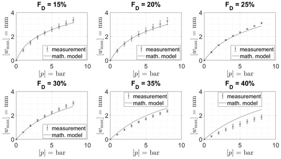
Figure 11.
The maximal deflection of the membrane under varying filling densities using pressure p was based on a model with the correction factor additive manufacturing , along with the measured values.
3.3. Pneumatic Network Actuator (PneuNet)
Individual airtight chambers, with their respective filling levels, were combined to form a PneuNet. Up to nine chambers were printed vertically (Ø = 17 mm; height = 76 mm) on a base platform in one piece from of the Freeformer. The printed PneuNet at a pressure of 8 bar is shown in Figure 12a,b. A higher bending angle was observed when the chamber was cut in the post-processing. A section cut through the actuator is shown in Figure 12c, so that different chamber fillings are visible. According to the previous results (Section 3.2), filling densities of 15%, 30%, 35%, and 40% were selected because they have large differences in their membrane deflection. Thus, the radius of curvature between the two chambers could be influenced.
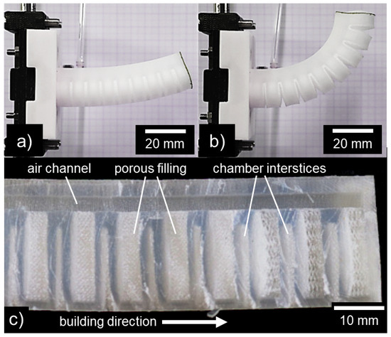
Figure 12.
PneuNet at pressure load of 8 bar without cut chamber interstices (a) and with cut chamber interstices (b). Different fill levels can be seen from a sectional view of a manually cut PneuNet (c).
Because Desmopan layers with an FD of 25% had to be printed between two chambers interstices for production-related reasons, the interstices were cut after printing. This allowed the full bending potential of the pneumatic net actuator to be exploited. A comparison of the bending angles of the PneuNet with and without a cut in the chamber interstices is shown in Figure 13. The bending angle increased by 60° at 8 bar, when the chamber interstices were cut.
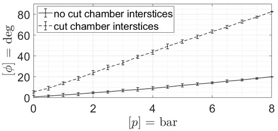
Figure 13.
Total bending angle of the PneuNet over pressure p with and without cut chamber interstices.
4. Discussion
The present study deals with the fabrication and characterization of a pneumatic net actuator via additive manufacturing using a Freeformer 300-3X (Arburg GmbH & Co. KG, Lossburg, Germany). Additive manufacturing enables customizable geometries and shorter production times than conventional processes such as casting. This could facilitate the realization of complex motion trajectories and enable cost-effective personalization when used in, e.g., medical devices. Especially for individual adaptation of motion patterns in the field of flexible endoscopy, this could be a decisive advantage.
By varying the filling densities, different membrane deflections of a PA could be achieved. A detailed analysis of the individual chambers, considering different filling densities, showed a clear dependence of the membrane deflection on the filling density.
The mathematical model developed to describe the membrane deflection gave satisfactory results. The inclusion of the strain energy of the filling, according to Hooke’s law, in the equations for membrane deflection improved the accuracy of the model. The factor represents the influence of additive manufacturing, especially the adhesion force of the droplet connections. However, this factor can only be determined experimentally, emphasizing the need for a more comprehensive mathematical description. The assumption that this factor depends on several parameters, such as printing speed, printing temperature, form factor, and filling density, opens up room for further investigation and analysis.
To utilize the full bending potential of the pneumatic net actuator, postprocessing was still required. The idea of making chamber interstices from water-soluble support material to facilitate this step has not yet been implemented, as this would compromise the airtightness of the structure. Nevertheless, the relatively simple post-processing already shows the potential of this actuator.
Further research is required to understand the behavior of the chambers when they expand in multiple directions, as is the case with a PneuNet. It is only then possible to develop a precise mathematical description of the entire actuator. This could lead to a better understanding of the performance and possible applications, and form the basis for the optimization of such actuators.
In addition, the additively manufactured porous inner filling will be investigated in more detail in the future. Of particular interest here is how the droplets bond with the neighboring droplets. This requires a suitable non-destructive visualization method such as a CT-scan.
It should be noted that only the use of thermoplastic polyurethane has been investigated here. Other materials can be used to further exploit the potential. The additive manufacturing process here was focused on feasibility. Further investigations with different material parameters and adaptation of the printing process could lead to actuators with improved mechanical properties, more reliable behavior and miniaturization.
5. Conclusions
In conclusion, this study successfully explored the additive manufacturing of PneuNet using a Freeformer. By strategically varying the filling densities within individual chambers, distinct membrane deflection behaviors were achieved. The developed mathematical model, enriched with the incorporation of the strain energy of the filling material, provided satisfactory results.
However, further investigation is warranted to understand the multidirectional expansion chamber behavior inherent in PneuNet. By exploiting the potential of additive manufacturing for intricate designs and personalized production, PA could play a pivotal role in the field of soft robotics and medical devices.
Author Contributions
Conceptualization, G.A.G.; methodology, G.A.G. and J.H.; software, G.A.G. and J.H.; validation, G.A.G. and J.H.; formal analysis, G.A.G.; investigation, G.A.G. and J.H.; resources, G.A.G. and P.P.P.; data curation, J.H.; writing—original draft preparation, G.A.G. and P.P.P.; writing—review and editing, G.A.G. and P.P.P.; visualization, G.A.G. and J.H.; supervision, P.P.P.; project administration, P.P.P.; funding acquisition, P.P.P. All authors have read and agreed to the published version of the manuscript.
Funding
This publication was funded by the German Research Foundation (DFG) grant “Open Access Publication Funding/2023-2024/University of Stuttgart” (512689491).
Institutional Review Board Statement
Not applicable.
Informed Consent Statement
Not applicable.
Data Availability Statement
The data presented in this study are available in the article.
Acknowledgments
The authors would like to thank the DFG for financial support (INST 41/1123 FUGG) to obtain the Freeformer 300-3X.
Conflicts of Interest
The authors declare no conflict of interest.
Abbreviations
The following abbreviations are used in this manuscript:
| a | radius of the clamping edge |
| filling Area | |
| droplet width | |
| droplet height | |
| D | Spring/filling constant |
| radial strain | |
| transverse strain | |
| E | Young’s modulus of the membrane |
| filling densities | |
| form factor | |
| h | thickness of the membrane |
| H | Actuator chamber height |
| correction factor additive manufacturing | |
| PA | pneumatic actuator |
| PneuNet | pneumatic network actuator |
| p | differential pressure on the membrane |
| r | radial coordinate |
| u | radial deflection |
| membrane strain energy | |
| filling strain energy | |
| v | Poisson’s ratio |
| maximum transverse deflection | |
| w | transverse deflection |
References
- Ashuri, T.; Armani, A.; Jalilzadeh Hamidi, R.; Reasnor, T.; Ahmadi, S.; Iqbal, K. Biomedical soft robots: Current status and perspective. Biomed. Eng. Lett. 2020, 10, 369–385. [Google Scholar] [CrossRef] [PubMed]
- Garcia, L.; Kerns, G.; O’Reilley, K.; Okesanjo, O.; Lozano, J.; Narendran, J.; Broeking, C.; Ma, X.; Thompson, H.; Njapa Njeuha, P.; et al. The Role of Soft Robotic Micromachines in the Future of Medical Devices and Personalized Medicine. Micromachines 2021, 13, 28. [Google Scholar] [CrossRef] [PubMed]
- Hentschel, L.; Kynast, F.; Petersmann, S.; Holzer, C.; Gonzalez-Gutierrez, J. Processing Conditions of a Medical Grade Poly(Methyl Methacrylate) with the Arburg Plastic Freeforming Additive Manufacturing Process. Polymers 2020, 12, 2677. [Google Scholar] [CrossRef] [PubMed]
- Stano, G.; Arleo, L.; Percoco, G. Additive Manufacturing for Soft Robotics: Design and Fabrication of Airtight, Monolithic Bending PneuNets with Embedded Air Connectors. Micromachines 2020, 11, 485. [Google Scholar] [CrossRef] [PubMed]
- Mosadegh, B.; Polygerinos, P.; Keplinger, C.; Wennstedt, S.; Shepherd, R.F.; Gupta, U.; Shim, J.; Bertoldi, K.; Walsh, C.J.; Whitesides, G.M. Pneumatic Networks for Soft Robotics that Actuate Rapidly. Adv. Funct. Mater. 2014, 24, 2163–2170. [Google Scholar] [CrossRef]
- Liu, Y.; Chen, W.; Xiong, C. Simulation and fabrication of a pneumatic network actuator with capability of bending in multi-planes. In Proceedings of the 2019 IEEE/ASME International Conference on Advanced Intelligent Mechatronics (AIM), Piscataway, NJ, USA, 8–12 July 2019; pp. 313–317. [Google Scholar] [CrossRef]
- Manns, M.; Morales, J.; Frohn, P. Additive manufacturing of silicon based PneuNets as soft robotic actuators. Procedia CIRP 2018, 72, 328–333. [Google Scholar] [CrossRef]
- Wang, T.; Ge, L.; Gu, G. Programmable design of soft pneu-net actuators with oblique chambers can generate coupled bending and twisting motions. Sens. Actuators A Phys. 2018, 271, 131–138. [Google Scholar] [CrossRef]
- Ge, L.; Wang, T.; Zhang, N.; Gu, G. Fabrication of Soft Pneumatic Network Actuators with Oblique Chambers. JoVE (J. Vis. Exp.) 2018, 138, e58277. [Google Scholar] [CrossRef]
- Wang, J.; Fei, Y.; Pang, W. Design, Modeling, and Testing of a Soft Pneumatic Glove With Segmented PneuNets Bending Actuators. IEEE/ASME Trans. Mechatron. 2019, 24, 990–1001. [Google Scholar] [CrossRef]
- Hu, W.; Mutlu, R.; Li, W.; Alici, G. A Structural Optimisation Method for a Soft Pneumatic Actuator. Robotics 2018, 7, 24. [Google Scholar] [CrossRef]
- von Zeppelin, D.; Manka, M. ARBURG Plastic Freeforming. Eng. Biomater. 2017, 143, 90. [Google Scholar]
- Charlon, S.; Le Boterff, J.; Soulestin, J. Fused filament fabrication of polypropylene: Influence of the bead temperature on adhesion and porosity. Addit. Manuf. 2021, 38, 101838. [Google Scholar] [CrossRef]
- Hermida, A. Deflection of circular membrane under differential pressure. NASA Tech Briefs Mag. 1998, 1998, 58. [Google Scholar]
Disclaimer/Publisher’s Note: The statements, opinions and data contained in all publications are solely those of the individual author(s) and contributor(s) and not of MDPI and/or the editor(s). MDPI and/or the editor(s) disclaim responsibility for any injury to people or property resulting from any ideas, methods, instructions or products referred to in the content. |
© 2023 by the authors. Licensee MDPI, Basel, Switzerland. This article is an open access article distributed under the terms and conditions of the Creative Commons Attribution (CC BY) license (https://creativecommons.org/licenses/by/4.0/).