Abstract
The permanent magnet eddy current coupling is widely used in fan and pump equipment as an energy-saving speed control device. The traditional coupling speed adjustment method occupies too much axial space, limiting its application in the process of upgrading old equipment. This paper proposes a novel flux adjustable permanent magnet eddy current coupling with a double-sided conductor to reduce the coupling axial distance while increasing the coupling output torque. The relative angle between the permanent magnet rings is controlled to adjust the output torque, and the double-sided conductor structure is used to improve the output torque. The working principle of the proposed design is illustrated. An analytical model for estimating the regulation performance of the proposed structure is proposed, which introduces the regulated reluctance into the equivalent magnetic circuit method. Based on this model, the expressions for magnetic flux density, eddy current density, and output torque are established. Finally, the accuracy of the analytical model was verified by the 3D finite element method, and the parameter sensitivity analysis was performed. The analysis results show that this device can achieve a relatively large range of output torque regulation under the condition of a fixed air gap, and the output torque is greatly improved by adopting a double-sided conductor structure.
1. Introduction
Permanent magnet eddy current coupling (PMECC) is an energy transfer device without mechanical contact that can achieve speed regulation of the load equipment by adjusting the air gap length [1,2,3,4]. The permanent magnet rotor in PMECC forms an air gap magnetic field that cuts the moving conductor, which generates induced eddy currents. The induced magnetic field generated by the induced eddy currents interacts with the original magnetic field to produce the load torque [5,6,7,8]. PMECC is widely used in large fan and pump loads and motor drive systems, with vibration isolation, energy efficiency, and no harmonic pollution [9,10,11,12]. As the requirement for energy efficiency increases, more and more old equipment needs energy-saving reconstruction, but the axial space is difficult to increase. Therefore, reducing the axial displacement of the coupling becomes meaningful.
Nehl et al. proposed the fundamental concept of permanent magnet eddy current coupling. The structure includes a conductor rotor and a permanent magnet rotor. The relative motion between the rotors achieves contactless energy transfer and a two-dimensional finite element method is used to analyze the device’s current density distribution and output torque characteristics. The relative motion of the permanent magnet rotor and the conductor rotor achieves contactless energy transfer. The loading speed can be flexibly adjusted by changing the axial air gap between the rotors. Moreover, the current density distribution and output torque characteristics of the device are analyzed by employing the two-dimensional finite element method [13]. To increase the output torque, Wallace A proposed an improved structure with a double-sided conductor rotor and a double-sided permanent magnet rotor [14]. Aldo Canova has designed two types of radial flux permanent magnet eddy current couplings, a single-sided permanent magnet rotor and a double-sided, permanent magnet rotor structure. The proposed structure avoids the problem of axial force generated by axial magnetic flux in PMECC [5]. Jang-Young Choi proposed an eddy current brake with Halbach permanent magnet array structure to enhance the output torque further [15]. To reduce magnetic leakage, Mohammadi proposed an axial flux built-in permanent magnet eddy current coupling [16]. Wang proposed a hybrid permanent magnet eddy current coupling, combining a radial flux coupling and two axial flux couplings. This structure improves the output torque and transfer efficiency [17]. Structural innovation is continuously developing for permanent magnet eddy current couplings.
However, the axial space of the old equipment is precious, and the air gap adjusting mechanism is bound to increase the axial space, which is necessary for the permanent magnet eddy current coupling to be improved. Fortunately, flux-adjustable permanent magnet eddy current coupling can achieve fixed air gap speed regulation, reducing the coupling’s axial space significantly. In recent years, some scholars have studied flux adjustable permanent magnet eddy current coupling. Tian proposed a radial flux permanent magnet eddy current coupling with a double-layer permanent magnet rotor, which changes the effective air gap flux by adjusting the relative position between the two permanent magnet layers to achieve output torque regulation [18]. Li proposed a hybrid excitation permanent magnet eddy current coupling, which adds a field excitation stator to the traditional field-controlled axial flux permanent magnet to achieve effective air gap flux regulation [19,20]. Subsequently, he proposed an interior permanent magnet eddy current coupling with a non-rotary mechanical flux adjuster. The main idea of the article is to reduce the area of the effective air gap flux by guiding the magnetic field through the ferrous adjuster to achieve output torque regulation [21,22]. Li proposed a novel flux-tunable permanent magnet eddy current coupler with three permanent magnet rotors, which achieves the optimization of the regulation methods and establishes the analytical model of the structure. However, the axial space occupied by the three permanent magnet rotors is large. In addition, the segmented torque calculation will produce errors at the boundary of the segmented interval [23]. Yang proposed a magnet-rotating-type axial magnetic coupling, which changes the air gap length by rotating the angle between the permanent magnet and the conductor rotor to adjust the output torque [4,24]. Kong proposed a flux-tunable permanent magnet eddy current coupler with three permanent magnet rings to further reduce axial space. An analytical model for the full working condition is proposed, but the analytical model is complicated [25]. Radial flux PMECC has severe problems with magnetic leakage, poor heat dissipation, and high installation requirements. In contrast, axial flux PMECC has apparent advantages over radial flux coupling in transfer efficiency, heat dissipation performance, and axial space. Therefore, the axial flux PMECC is employed in this paper. Yang also adopts the axial flux structure, but the proposed improvement cannot achieve the full range of output torque regulation, which limits its application range.
In this paper, a novel double-sided conductor flux adjustable PMECC (DCFA-PMECC) is proposed. The output torque of the load can be regulated by changing the relative angle of the adjusted permanent magnet ring and the fixed permanent magnet ring. The proposed DCFA-PMECC realizes flux regulation under a fixed air gap and reduces the axial space of the coupling. To evaluate the performance of the proposed coupling, an analytical model of the coupling based on the equivalent circuit method is established. The innovation of this method is to introduce the dynamic process of regulation reluctance to simulate the relative angle change of APR and FPR and to calculate the eddy current and output torque under the asymmetric magnetic field. Finally, the accuracy of the model is verified by the three-dimensional finite element method, and sensitivity analysis is performed on the structural parameters. The analysis results show that the proposed structure can achieve the full range of output torque regulation.
2. Topology
The structure of the proposed DCFA-PMECC is shown in Figure 1, which consists of a permanent magnet rotor (PMR), an upper conductor rotor (UCR), and a lower conductor rotor (LCR), all of which are coaxial. Different from the conventional PMECC, the PMR is composed of an external fixed permanent magnet ring (FPR), an internal fixed permanent magnet ring, and adjustable permanent magnet ring (APR), with the permanent magnets arranged in alternating magnetization directions and fixed in the iron core. The magnetization direction is circumferential. The copper disk in the conductor rotor is closely mounted with the back iron and has an air gap with the PMR, and the APR is controlled to rotate to adjust the relative position of the APR and FPR. In addition, the parameter symbols of the proposed coupling are shown in Figure 2 cross-sectional drawing, where Figure 2a shows the cross-section at the average radius and Figure 2b shows the cross-section in the radial direction.
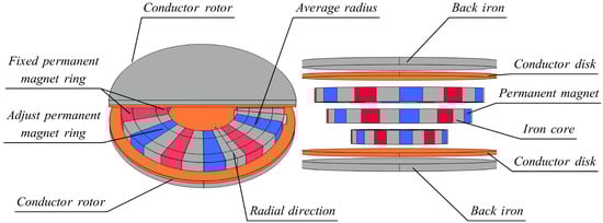
Figure 1.
The structure of the proposed DCFA-PMECC.
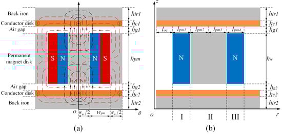
Figure 2.
Structural parameters and magnetic flux path of DCFA-PMECC: (a) Cross section at average radius, (b) cross section in the radial direction.
3. Analytical Model
Figure 3 shows the flux distribution for the three regulation states, where Figure 3a shows the initial moment of state 1, where there is no mechanical angle between the permanent magnets of the FPR and those of the APR. Most of the magnetic fluxes pass through the copper disk to form loops. At this state, the effective air gap flux density is maximum, and the output torque is largest; the magnetic field distribution changes with the gradual increase in the relative angle between APR and FPR. Figure 3b shows the magnetic field distribution of the relative angle between 0 to 15 degrees. The magnetic flux is divided into three parts: the first part forms a loop through the copper disk, the second part is the permanent magnets form a loop through the iron core and air gap, and the third part is the permanent magnets NS of APR and the permanent magnets SN of FPR forming a loop through the copper disk. As the relative angle increases, the effective air gap flux through the copper disk decreases, and the leakage flux between the APR and FPR increases, eventually decreasing output torque. When the relative angle of APR reaches 15 degrees, the magnetic flux distribution is shown in Figure 3c. In this case, the iron core of FAR and the spaced iron core of APR are properly contacted, resulting in a reduction of the equivalent reluctance, and most of the flux passes through the iron core to form a loop with the permanent magnets. The green flux in Figure 3b changes to purple flux in Figure 3c. In addition, the regulation leakage flux between the APR and FPR adjacent permanent magnets is significantly increased. At this time, the effective air gap flux density is reduced to 0.06T, and the output torque is close to zero. To obtain the analytical model of the proposed DCFA-PMECC, the following assumptions are made.
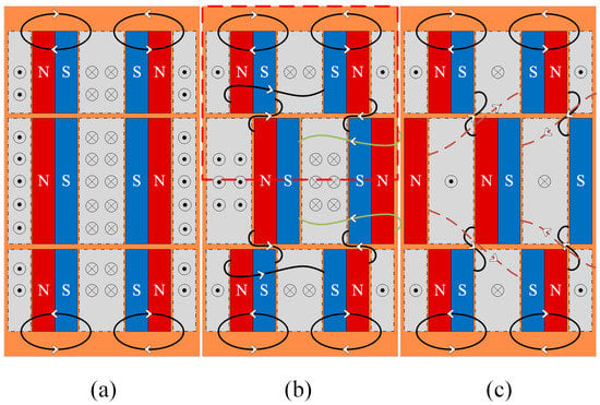
Figure 3.
Flux distribution of DCFA-PMECC at regulation state: (a) , (b) , and (c) .
(1) The relative permeability of ferromagnetic materials is a constant and is not affected by environmental factors.
(2) All the field quantities are periodically symmetrically distributed in the radial direction.
(3) The influence of magnetic saturation and end effects on the calculation is not considered.
(4) Set the radial length of APR equal to the radial length of UFPR plus the radial length of LFPR, because the magnetic field generated by APR has to be the same as that of FPR to achieve the flux symmetry balance regulation.
3.1. Field Analysis
To visualize the magnetic field distribution under regulation, the static magnetic field distribution is first analyzed by ignoring the effect of the induced magnetic field. To intuitively analyze the magnetic field distribution under the regulation state, first analyze the static magnetic field distribution without considering the influence of the induced magnetic field. Since the inner FPR and outer FPR are arranged symmetrically, only the magnetic equivalent magnetic circuit model of the outer FPR permanent magnet and the APR half of the permanent magnet is considered. Considering the small air gap between FPR and APR, the effect of the air gap between the two rings on the magnetic field is ignored. Figure 4 shows the two-dimensional flux closed-loop diagram of upper part one half pole pair, where the fluxes include effective air gap flux, leakage flux, regulation effective flux, and regulation leakage flux. The red dashed part in Figure 3b is the upper part one-half pole pair. The magnetomotive force of the permanent magnets in FPR and APR can be calculated as follows:
where is the coercivity of the permanent magnet; and is the radial length of the permanent magnet.
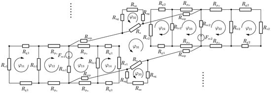
Figure 4.
Equivalent circuit diagram of upper part one half pole pair.
The magnetic flux equation in the equivalent magnetic circuit model based on Kirchhoff’s voltage law can be established as follows:
where is the magnetic flux of the flux loop in Figure 4. The flux loop is divided into three parts, I is the equivalent loop of the FAR part, is the equivalent loop of the APR part, and is the equivalent loop of the regulation reluctance part, where the equivalent reluctance of the I part can be expressed as
where is the equivalent reluctance of the FPR permanent magnet, is the air gap reluctance between FPR and the upper conductor disk, is the air gap reluctance between FPR and the lower conductor disk, and the reluctance of the air gap and copper disk can be combined due to the approximate permeability of air and copper. is the leakage reluctance of the upper conductor disk and FPR, is the leakage reluctance of the lower conductor disk and FPR, and is the reluctance of the iron core of FPR.
where is the vacuum permeability. is the relative permeability of the permanent magnet. is the radial offset leakage distance of the permanent magnet, . is the relative offset distance between APR and FPR, , and is the relative angle. is the area of air gap reluctance change due to the relative angle change. is the equivalent area of the permanent magnet iron core of the FAR. is the area of the iron core change.
where and are the equivalent surface area of the iron core in the UFPR, and the equivalent surface area of the permanent magnets in the UFPR, respectively. is the equivalent change area of the permanent magnet in UFPR, which can be calculated according to the principle of the shortest magnetic circuit as follows:
Similarly, part is the equivalent loop equation of APR, where the reluctance to can be expressed as follows:
where , , , , , and denote the equivalent reluctance of the permanent magnets in the APR, the air gap reluctance between the APR and the upper conductor disk, the air gap reluctance between the APR and the lower conductor disk, the leakage reluctance between the upper conductor disk and the APR, the leakage reluctance between the lower conductor disk and the APR, and the equivalent reluctance of iron core in APR, respectively.
where is the area of air gap reluctance change, is the equivalent area of permanent magnet core of FAR, and is the area of core change, which can be calculated as follows:
where and are the equivalent surface area of the iron core in the APR, and the equivalent surface area of the permanent magnets in the APR, respectively. is the equivalent change area of the permanent magnet in APR, which can be calculated according to the principle of the shortest magnetic circuit as follows:
Part is the equivalent circuit of the regulation section, where the reluctance to can be expressed as follows:
where is the regulation reluctance, is the regulation air gap reluctance, is the iron core reluctance through the regulation loop, is the back iron reluctance through the conductor rotor in the regulation loop.
where is the effective air gap flux area of the regulation loop
The DCFA-PMECC is symmetrical for both sides of the conductor rotor, and the magnetic field on the surface of the conductor disc is periodically distributed. Therefore, considering the static magnetic flux density on the surface of the conductor disc on one side for 1/2 pole pairs is sufficient. The approximate axial component can be estimated as follows:
3.2. Induction Field Analysis
The flux distribution of DCFA-PMECC in the dynamic case is shown in Figure 2a. The red loop is the static magnetic field generated by the permanent magnet with the direction of the eddy current perpendicular to the paper, and the black loop is the induced magnetic field generated by the eddy current. The induced magnetic field and the static magnetic field are superimposed to form the air-gap magnetic field, and the air-gap flux density can be calculated as follows:
Based on the law of electromagnetic induction, the density of eddy currents in the copper disk can be calculated as follows:
where is the conductivity of copper, is the slip angular velocity between the conductor rotor and the permanent magnet rotor, and is the average radius of the permanent magnet rotor.
The equation for the integral form of is obtained according to the Ampere Loop Theorem as follows:
According to the boundary conditions, the general solution of the induced magnetic flux density is as follows:
where , , .
The analytical equation for the total air-gap flux density of UFPR when considering eddy current effects is obtained as follows:
The analytical equation for the total air-gap flux density of APR and the regulating magnetic flux part under the condition of considering the eddy current effect are obtained as follows:
3.3. Torque Calculation
The eddy current in the rotor of the DCFA-PMECC conductor produces output torque along with eddy current loss, so the output torque is closely related to the eddy current loss. The eddy current loss on the copper disk can be expressed as follows:
where is the length of the regulation reluctance
The three-dimensional axial distribution of the eddy current needs to be considered, and the Russell–Norsworthy factor is used to correct the two-dimensional model, as given below:
As a result, the output torque of the upper part of one-half polar pair can be obtained as follows:
Similarly, the output torque of the lower part one-half pole pair can be calculated as follows:
where is the Russell–Norsworthy factor of the lower part of the one-half pole pair. is the length of the lower part regulation reluctance. , , are the lower part APR eddy current density, LFPR eddy current density, regulation section eddy current density, respectively.
Iron loss mainly exists in the conductor disc back iron, can be calculated as follows:
where is the iron consumption coefficient, f is the slip frequency, B is the iron core magnetic density, and m is the rotor iron core weight.
The input power of DCFA-PMECC mainly consists of three parts: iron loss, copper loss, and output power, the output power and mechanical efficiency of DCFA-PMECC are as follows:
4. Figures and Tables
In this section, the output torque equation Equation (28) is used to predict the performance of the coupling in regulation states and to verify the accuracy of the proposed model. The results are compared with the 3D finite element simulation model. The magnetic field distribution and eddy current density in different regulation states are compared extensively. The sensitivity analysis of the structure parameters is performed to evaluate the proposed structure’s eddy current loss and efficiency. The main structural parameters of the proposed DCFA-PMECC are shown in Table 1.

Table 1.
Parameters of the studied model.
4.1. Magnetic Field Distribution
Figure 5 shows the 3D finite element simulation results of the coupling at 120 rpm with the relative angle varying from 0 to 15 degrees. The magnetic field distribution is shown on the left side of the figure, and the eddy current distribution is shown on the right side. As can be seen from the figure, the location of the eddy current distribution corresponds to the location of the magnetic flux density, and the stronger the magnetic flux density, the greater the eddy current density. The magnetic flux density decreases with increasing relative angle. Figure 5a–c shows the flux density distribution and eddy current distribution of the conductor rotor at state 1, state 2, and state 3, respectively. At state 1, the maximum flux density of the conductor rotor is 0.83 T, and the maximum eddy current density is A/m, and the strongest magnetic field is concentrated in the corresponding position of the iron core. As shown in Figure 5b, the flux density at the APR position gradually decreases as the relative angle increases. A part of the regulation flux loop forms a loop through the air gap and the iron core, and another part forms a loop through the iron core and the copper disk, resulting in a decrease in the effective air gap flux density and eddy current density. When the relative angle reaches 15 degrees, the flux density distribution is shown in Figure 5c. The flux passes through the iron core and air gap, the maximum effective air gap flux density drops significantly to 0.068 T, and the eddy current density drops to A/m, and the output torque tends to zero at this time. Continuing to increase the relative angle, the flux density on the surface of the copper disk decreases further, but the effect on the output torque results is so weak that it is not considered.
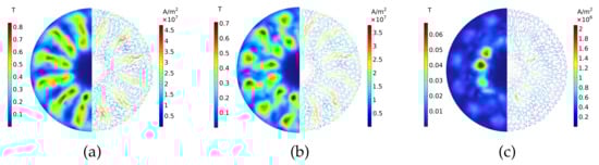
Figure 5.
Magnetic field intensity and eddy current density distribution on the surface of the copper disk at different relative angles: (a) , (b) , (c) .
4.2. Output Torque Regulation Characteristic
To analyze the relationship between slip speed and output torque and the accuracy of the analytical model, the output torque from the analytical calculation was compared with the corresponding results from the 3D finite element model. The air gap thickness is fixed at 3 mm, and the slip speed is adjusted from 0 rpm to 150 rpm. The characteristic curve of the output torque with the variation of the slip speed is shown in Figure 6a. The output torque increases linearly with increasing slip speed, and the results fit better at low slip speeds. When the slip speed exceeds 120 rpm, the analytical calculation results gradually exceed the FEM results. The results of the analytical and FEM models at different relative angles in the figure are in relatively close agreement, and the relative error is below on average. The analysis results show that the accuracy of the improved equivalent magnetic circuit model is better within the normal operating range of the coupling. Compared with the single conductor flux adjustable PMECC under the same slip speed condition, the output torque growth rate is up to 89.4%. The output torque of the proposed DCFA-PMECC is significantly increased.
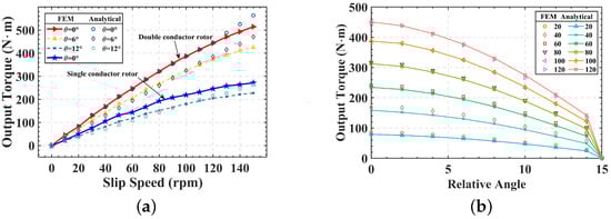
Figure 6.
Output torque—slip speed characteristic curve (a) compared with single-conductor rotor structure; (b) output torque-relative angle characteristic curves.
In Figure 6b, the output torque-relative angle characteristic curves of the proposed DCFA-PMECC are predicted by the analytical method and compared with the 3D finite elements. The relative angle range from 0 to 15 degrees at an air gap of 3 mm. As can be observed from Figure 6, the results of the analytical model calculations are very close to those of the 3D finite element model over the entire relative angle range. The results show that the proposed DCFA-PMECC can achieve the full range of output torque regulation under a fixed air gap and significantly reduce the axial space occupied by the adjusting mechanism.
4.3. Sensitivity Analysis of Structural Parameters
Based on the structural parameters in Table 1, sensitivity analysis is performed on the pole arc coefficient, air gap thickness, and pole pairs of the proposed DCFA-PMECC. The effects of different parameters on the output torque are investigated to provide a basis for the coupling design.
The output torque-slip speed characteristic curves are given in Figure 7a for six different pole arc coefficients from 0.5 to 1 with differential speed regulation in the range of 0 rpm to 120 rpm. The output torque gradually increases with the increase in the pole arc factors. There is a negative growth in output torque when the pole arc coefficient increases to 1. The increments of the output torque for different pole arc factors are shown in Figure 7b. The increase in output torque slows down as the arc factor increases. The increase in output torque slows down as the arc factor increases. As can be seen from Figure 7b, the increments of the pole arc factors 0.7 and 0.8 are the same, indicating that the output torque varies linearly between 0.6 and 0.8. The result shows that as the pole arc factors increase, the device’s energy efficiency ratio per unit volume decreases, and the appropriate pole arc factor should be selected according to the output torque demand.
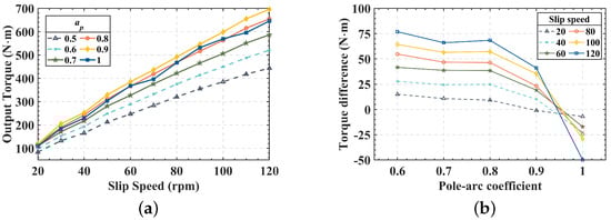
Figure 7.
Polar arc coefficient—output torque characteristic curve (a) output torque under different slip speed; (b) output torque difference at different polar arc coefficient.
The air gap is a crucial factor affecting the performance of the Coupling. To investigate its effect on the output torque, the slip speed-output torque characteristics under the air gap variation from 1 to 30 mm are analyzed, and the results are shown in Figure 8a Output torque decreases with the increasing air gap. The increments between different air gaps are shown in Figure 8b. From the graph, it is evident that the output torque drop rate fluctuates up and down when the air gap is between 1–5 mm. When the air gap exceeds 5 mm, the output torque drop rate decreases slowly and finally drops to zero as the air gap continues to increase. The results show that the air gap regulation causes a high degree of nonlinearity in the output torque, making it difficult to control the output torque accurately.
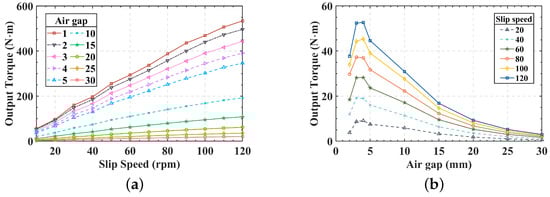
Figure 8.
Air gap—output torque characteristic curve: (a) output torque under different slip speed; (b) output torque increments at different air gap.
Figure 9a shows the pole pairs-output torque characteristics of the slip speed in the 20 rpm to 120 rpm range. The graph shows that there is a gradual increase with the number of pole pairs rising from 4 to 8. A possible reason for this phenomenon is that the eddy current distribution position corresponds to the permanent magnet, and the number of eddy current rings will increase with the increase in the number of pole pairs, while the flux density does not change, which eventually makes the output torque rise. The amount of output torque decreases after the 8 pole pairs. The reason for this phenomenon is that increasing the number of pole pairs decreases the pole spacing, resulting in a significant increase in the leakage flux between adjacent permanent magnets and a decrease in the effective air gap flux. Figure 9b shows the polar pair-output torque characteristic curves for the relative angle varying from 0 to 15 degrees. The results show that the peak output torque is concentrated around 8 pole pairs, and the optimal pole pairs do not vary with the relative angle.
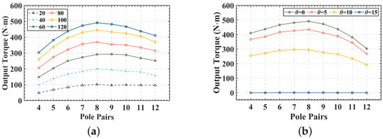
Figure 9.
Pole pair—output torque characteristic curve: (a) output torque at different slip speed; (b) output torque at different relative angle.
4.4. Dynamic Characteristics
Figure 10a shows the time-output torque characteristics under different slip speeds, and Figure 10b shows the time-output torque characteristics with a sudden change of slip speed during operation. At the initial stage, there is no eddy current in the conductor disc. With the addition of slip speed, the eddy current in the conductor rotor gradually increases, the output torque increases, and the final output torque tends to be dynamic stability. In Figure 10b, the yellow line shows that the slip speed decreases from 90 rpm to 40 rpm, and the blue line shows that the slip speed increases from 30 rpm to 80 rpm. The slip speed starts to change at 0.05 s and ends at 0.06 s. The output torque rapidly reaches a new dynamic stability state with the change of the slip speed.
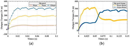
Figure 10.
Dynamic characteristics of DCFA—PMECC (a): Time—output torque characteristics at different slip speed; (b) Time—output torque characteristics of slip speed sudden change.
4.5. Loss and Efficiency
The structural parameters of the coupling refer to Table 1. The characteristic curves of copper loss, iron loss, and efficiency of the coupling are shown in Figure 11 with the settings of different slip speeds. As can be seen from the graph, with the increase in the speed of the difference from 20 rpm to 120 rpm, the copper loss increases from 0.16 kW to 5.84 kW, and the iron loss increases from 1.3 W to 13.9 W. The copper loss is much larger than the iron loss, and the coupling efficiency decreases as the slip speed increases.
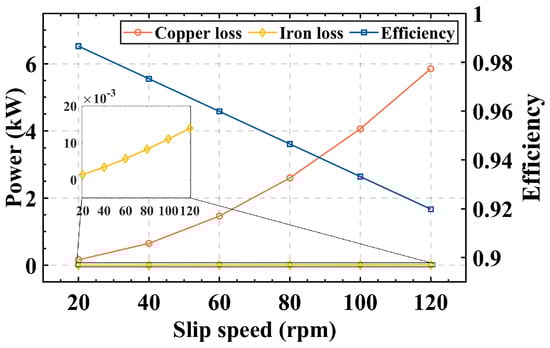
Figure 11.
The copper loss, iron loss, and efficiency of the DCFA-PMECC.
5. Conclusions
In this paper, a novel double-sided conductor flux adjustable permanent magnet eddy current coupling has been proposed, which realizes the effective regulation of output torque by adjusting the relative angle of APR and FPR. It significantly reduces the axial space occupied by the traditional coupling air gap regulation device and solves the axial space limitation problem for upgrading old equipment. The double-sided conductor structure is also used to increase the output torque and reduce the leakage of permanent magnets. A variable regulation reluctance model based on the equivalent magnetic circuit method is proposed to simulate the whole variation state. The output torque of the proposed model is predicted using this method and compared with the 3D finite element model. The results demonstrate the proposed analytic model’s high accuracy in the slip speed range of less than 120 rpm. The maximum output torque is 445 N*m when the relative angle is 0 degrees and decreases to 0.23 N*m when the relative angle is increased to 15 degrees, which shows that the proposed DCFA-PMECC can achieve almost the full range of output torque regulation. Subsequently, the sensitivity of the structural parameters of the proposed DCFA-PMECC was analyzed, and the results showed that the increase in the pole arc coefficient led to higher output torque. However, the energy efficiency ratio per unit volume of the device decreased. The output torque decreases non-linearly as the air gap increases. The air gap decreases rapidly in the range of 0 to 5 mm and decreases gradually after the air gap exceeds 5 mm. Compared with the single conductor flux adjustable PMECC, the proposed DCFA-PMECC improves the output torque by up to 89.4% at the same slip speed. The study in this paper shows that the proposed DCFA-PMECC can achieve a nearly full range of output torque regulation at the fixed air gap and effectively increase the output torque of the coupler.
Author Contributions
Conceptualization, D.K. and D.W.; methodology, D.K., D.W., Y.N. and K.S.; software, D.K. and Y.Q.; validation, Y.Q. and Y.L.; formal analysis, D.K. and D.W.; investigation, D.K., D.W. and Y.Q.; resources, D.W.; data curation, D.K. and D.W.; writing—original draft preparation, D.K. and D.W.; writing—review and editing, D.K., D.W., Y.N., K.S., Y.Q. and Y.L.; visualization, Y.Q. and Y.L.; supervision, D.W.; project administration, D.W.; funding acquisition, D.W. All authors have read and agreed to the published version of the manuscript.
Funding
This work is supported by the National Natural Science Foundation of China under Grant 52077027 and Shenyang Major Technical Research Project, China No. 2022021000014.
Institutional Review Board Statement
Not applicable.
Informed Consent Statement
Not applicable.
Data Availability Statement
The data presented in this study are available on request from the corresponding author.
Conflicts of Interest
The authors declare no conflict of interest. The funders had no role in the design of the study; in the collection, analyses, or interpretation of data; in the writing of the manuscript; or in the decision to publish the results.
Nomenclatures
| The magnetomotive force of the permanent magnets in FPR | |
| The magnetomotive force of the permanent magnets in APR | |
| The coercivity of the permanent magnet | |
| The conductivity of the conductor | |
| The slip angular velocity between the conductor rotor and the permanent magnet rotor | |
| B | The iron core magnetic density |
| The remanent magnetic flux density of the PM | |
| The vacuum permeability | |
| The relative permeability of the permanent magnet | |
| The relative permeability of the iron core | |
| p | The number of pole pairs |
| The radial length of the permanent magnet | |
| The radial length of the iron core | |
| The air-gap length bettwen UCR and PMR | |
| The thickness of copper disk in UCR | |
| The iron core thickness | |
| The air-gap length bettwen LCR and PMR | |
| The thickness of copper disk in LCR | |
| The magnet thickness | |
| The magnet height of UFPR | |
| The half magnet height of APR | |
| The half magnet height of APR | |
| The magnet height of LFPR | |
| The air-gap reluctance between FPR and the upper conductor disk | |
| The air-gap reluctance between the APR and the upper conductor disk | |
| The air-gap reluctance between FPR and the lower conductor disk | |
| The air-gap reluctance between the APR and the lower conductor disk | |
| The equivalent reluctance of the back iron in the FPR | |
| The equivalent reluctance of the back iron in the APR | |
| The leakage reluctance of the upper conductor disk and FPR | |
| The leakage reluctance of the lower conductor disk and FPR | |
| The reluctance of the iron core of FPR | |
| The equivalent reluctance of the FPR permanent magnet | |
| The leakage reluctance between the upper conductor disk and the APR | |
| The leakage reluctance between the lower conductor disk and the APR | |
| The equivalent reluctance of the permanent magnets in the APR | |
| The equivalent reluctance of iron core in APR | |
| The regulation reluctance | |
| The regulation air gap reluctance | |
| The iron core reluctance through the regulation loop | |
| The back iron reluctance through the conductor rotor in the regulation loop | |
| The average radius of the permanent magnet rotor | |
| J | The density of eddy currents in the copper disk |
| The Russell–Norsworthy factor of upper part one-half polar pair | |
| The Russell–Norsworthy factor of lower part one-half polar pair | |
| The iron consumption coefficient | |
| f | The slip frequency |
| The relative angle | |
| The length of the upper part regulation reluctance | |
| The length of the lower part regulation reluctance |
References
- Dai, X.; Liang, Q.; Cao, J.; Long, Y.; Mo, J.; Wang, S. Analytical Modeling of Axial-Flux Permanent Magnet Eddy Current Couplings With a Slotted Conductor Topology. IEEE Trans. Magn. 2016, 52, 8000315. [Google Scholar] [CrossRef]
- Mohammadi, S.; Kirtley, J.; Niaz Azari, M. Modelling of Axial-flux Eddy-current Couplers. IET Electr. Power Appl. 2020, 14, 1238–1246. [Google Scholar] [CrossRef]
- Belguerras, L.; Mezani, S.; Lubin, T. Analytical Modeling of an Axial Field Magnetic Coupler with Cylindrical Magnets. IEEE Trans. Magn. 2021, 57, 8000305. [Google Scholar] [CrossRef]
- Kenne Telezing, B.J.; Yang, C.; Ombolo, P.D.; Peng, Z.; Tai, J.; Zhu, L. Torque Characteristics Analysis of a Novel Hybrid Superconducting Magnetic Coupling With Axial-Flux Using a Magnetic Equivalent Circuit Model. IEEE Access 2022, 10, 45594–45604. [Google Scholar] [CrossRef]
- Canova, A.; Vusini, B. Analytical Modeling of Rotating Eddy-Current Couplers. IEEE Trans. Magn. 2005, 41, 24–35. [Google Scholar] [CrossRef]
- Lubin, T.; Rezzoug, A. 3-D Analytical Model for Axial-Flux Eddy-Current Couplings and Brakes Under Steady-State Conditions. IEEE Trans. Magn. 2015, 51, 8203712. [Google Scholar] [CrossRef]
- Lubin, T.; Rezzoug, A. Steady-State and Transient Performance of Axial-Field Eddy-Current Coupling. IEEE Trans. Ind. Electron. 2015, 62, 2287–2296. [Google Scholar] [CrossRef]
- Lubin, T.; Mezani, S.; Rezzoug, A. Simple Analytical Expressions for the Force and Torque of Axial Magnetic Couplings. IEEE Trans. Energy Convers. 2012, 27, 536–546. [Google Scholar] [CrossRef]
- Jin, P.; Tian, Y.; Lu, Y.; Guo, Y.; Lei, G.; Zhu, J. 3-D Analytical Magnetic Field Analysis of the Eddy Current Coupling With Halbach Magnets. IEEE Trans. Magn. 2020, 56, 7501904. [Google Scholar] [CrossRef]
- Wallace, A.; von Jouanne, A. Industrial Speed Control: Are PM Couplings an Alternative to VFDs? IEEE Ind. Appl. Mag. 2001, 7, 57–63. [Google Scholar] [CrossRef]
- Wallace, A.; von Jouanne, A.; Williamson, S.; Smith, A. Performance Prediction and Test of Adjustable, Permanent-Magnet, Load Transmission Systems. In Proceedings of the Conference Record of the 2001 IEEE Industry Applications Conference, Chicago, IL, USA, 30 September–4 October 2001; 36th IAS Annual Meeting (Cat. No.01CH37248). IEEE: Chicago, IL, USA, 2001; Volume 3, pp. 1648–1655. [Google Scholar] [CrossRef]
- Tonoli, A.; Amati, N. Dynamic Modeling and Experimental Validation of Eddy Current Dampers and Couplers. J. Vib. Acoust. 2008, 130, 021011. [Google Scholar] [CrossRef]
- Nehl, T.; Lequesne, B.; Gangla, V.; Gutkowski, S.; Robinson, M.; Sebastian, T. Nonlinear Two-Dimensional Finite Element Modeling of Permanent Magnet Eddy Current Couplings and Brakes. IEEE Trans. Magn. 1994, 30, 3000–3003. [Google Scholar] [CrossRef]
- Wallace, A.; Lamb, K. A High Efficiency, Alignment and Vibration Tolerant, Coupler Using High Energy-Product Permanent Magnets. IEE Conf. Publ. 1995, 5, 232–236. [Google Scholar] [CrossRef]
- Choi, J.Y.; Jang, S.M. Analytical Magnetic Torque Calculations and Experimental Testing of Radial Flux Permanent Magnet-Type Eddy Current Brakes. J. Appl. Phys. 2012, 111, 07E712. [Google Scholar] [CrossRef]
- Mohammadi, S.; Mirsalim, M.; Vaez-Zadeh, S.; Talebi, H.A. Analytical Modeling and Analysis of Axial-Flux Interior Permanent-Magnet Couplers. IEEE Trans. Ind. Electron. 2014, 61, 5940–5947. [Google Scholar] [CrossRef]
- Wang, S.; Guo, Y.; Cheng, G.; Li, D. Performance Study of Hybrid Magnetic Coupler Based on Magneto Thermal Coupled Analysis. Energies 2017, 10, 1148. [Google Scholar] [CrossRef]
- Tian, M.; Zhao, W.; Wang, X.; Wang, D.; Yang, Y.; Diao, J.; Ma, X. Analysis on a Novel Flux Adjustable Permanent Magnet Coupler With a Double-Layer Permanent Magnet Rotor. IEEE Trans. Magn. 2018, 54, 8109205. [Google Scholar] [CrossRef]
- Li, Y.; Lin, H.; Yang, H.; Fang, S.; Wang, H. Analytical Analysis of a Novel Flux Adjustable Permanent Magnet Eddy-Current Coupling with a Movable Stator Ring. IEEE Trans. Magn. 2018, 54, 8000404. [Google Scholar] [CrossRef]
- Li, Y.; Lin, H.; Huang, H.; Yang, H.; Tao, Q.; Fang, S. Analytical Analysis of a Novel Brushless Hybrid Excited Adjustable Speed Eddy Current Coupling. Energies 2019, 12, 308. [Google Scholar] [CrossRef]
- Li, Y.; Lin, H.; Tao, Q.; Lu, X.; Yang, H.; Fang, S.; Wang, H. Analytical Analysis of an Adjustable-Speed Permanent Magnet Eddy-Current Coupling With a Non-Rotary Mechanical Flux Adjuster. IEEE Trans. Magn. 2019, 55, 5. [Google Scholar] [CrossRef]
- Li, Y.; Lin, H.; Yang, H. A Novel Squirrel-Cage Rotor Permanent Magnet Adjustable Speed Drive With a Non-Rotary Mechanical Flux Adjuster. IEEE Trans. Energy Convers. 2021, 36, 1036–1044. [Google Scholar] [CrossRef]
- Li, Z.; Zhang, L.; Qu, B.; Yang, H.; Wang, D. Evaluation and Analysis of Novel Flux-adjustable Permanent Magnet Eddy Current Couplings with Multiple Rotors. IET Electr. Power Appl. 2021, 15, 754–768. [Google Scholar] [CrossRef]
- Yang, F.; Zhu, J.; Yang, C.; Ding, Y.; Hang, T. A Simple Method to Calculate the Torque of Magnet-Rotating-Type Axial Magnetic Coupler Using a New Magnetic Equivalent Circuit Model. IEEE Trans. Magn. 2022, 58, 8003212. [Google Scholar] [CrossRef]
- Deshan, K.; Dazhi, W.; Wenhui, L.; Sihan, W.; Zhong, H. Analysis of a Novel Flux Adjustable Axial Flux Permanent Magnet Eddy Current Coupler. IET Electr. Power Appl. 2023, 17, 181–194. [Google Scholar] [CrossRef]


Disclaimer/Publisher’s Note: The statements, opinions and data contained in all publications are solely those of the individual author(s) and contributor(s) and not of MDPI and/or the editor(s). MDPI and/or the editor(s) disclaim responsibility for any injury to people or property resulting from any ideas, methods, instructions or products referred to in the content. |
© 2023 by the authors. Licensee MDPI, Basel, Switzerland. This article is an open access article distributed under the terms and conditions of the Creative Commons Attribution (CC BY) license (https://creativecommons.org/licenses/by/4.0/).