Abstract
The wearable force feedback glove provides a promising solution for enhancing immersion during teleoperation. In this study, a lightweight five-finger exoskeleton force feedback glove (EFFG) was designed, enabling driving force detection and flexible force feedback. This wireless prototype weighs only 278 g. The glove features a bionic structure and optimized linkage length to ensure operator safety while providing extensive coverage of the finger working space. Moreover, a detailed illustration of the kinematic and dynamic analyses, as well as the circuit structure, was presented. With this prototype as the basis, an isomorphic teleoperation system is designed to achieve force feedback during teleoperation. Concurrently, a driving force-based impedance controller was proposed to enable smooth and precise force feedback. Finally, the performance of the EFFG prototype was evaluated in both unconstrained and constrained environments, demonstrating that the proposed glove is lightweight, capable of detecting driving force, and provides flexible force feedback.
1. Introduction
Effective force interaction is crucial for the human–machine interface during teleoperation. It is difficult to make accurate decisions if the operator lacks a sense of the working environment [1]. As an intuitive and effective force interaction mechanism, the force feedback glove allows users to touch and manipulate virtual objects in an intuitive and direct way via the dexterous manipulation and sensitive perception capabilities of the hands [2], which significantly enhances their ability to understand the remote scene [3].
Over the past decade, force feedback devices with various mechanisms have been proposed and widely adopted in virtual reality [4], human–machine teleoperation [5,6,7], micromanipulation [8], medical training, and rehabilitation [9,10]. Based on their working principle and working space, force feedback devices can be classified into grounded and ungrounded devices [11]. Grounded force feedback devices are fixed in place and apply force from the ground (or from a desk) [12]; many products of this type have been put forward, and various end effectors such as pens [13,14], scissors [15,16], and soft balls have been used depending on the purpose of the system. However, the restricted workspace makes it difficult for the user to move freely, thus leading to a lack of flexibility. This is effectively addressed by ungrounded feedback devices, in which the interaction force derived from the operator is applied to other parts of the user’s body, allowing for a significant improvement in flexibility and enabling the user to feel the virtual object more naturally.
Ungrounded feedback devices, also known as wearable force feedback devices, can be divided into active feedback force and passive feedback force according to working principle. Compared with gloves providing active feedback force, gloves with passive feedback force are promising in terms of safety and low weight, but simulating the variable stiffness of virtual objects is more challenging. Therefore, Wang D X et al. [17] proposed a variable stiffness passive force feedback, in which the stiffness of the glove is tuned by changing the structural stiffness; the switch between free and constrained space is realized in real time by locking/unlocking the revolute joints of the glove using a servo motor, but the structure is complex. Wang D M et al. [18] developed a force feedback glove using a magnetorheological (MR) damper to provide viable feedback force, while it has the shortcoming of a slow response time.
Compared with the passive force feedback gloves, the active force feedback can provide flexible stiffness and variable feedback force, which has been adopted in various commercial force feedback devices. The CyberGrasp [19] is one of the most successful haptic gloves available on the market. The actuation tendons pull the glove mechanism to provide force feedback up to 12 N to each finger in the direction opposite the fingers closing (only one direction force feedback). The glove mounted on the back of the hand weighs 350 g, but the separate control and actuator unit has a weight of 20 kg, which makes the device’s portability difficult. Due to lack of position sensors, the CyberGrasp needs an extra data glove (CyberGlove) to provide sensing. To solve this problem, Zhou M et al. [20] proposed a sensing and force-feedback exoskeleton (SAFE) glove. The glove is a wireless and self-contained mechatronic system that mounts over the dorsum of a bare hand and provides haptic force feedback to each finger. A force sensor is installed at the end of the glove to sense fingertip force, but due to the complex structure, the glove only achieved two fingers, and the weight was 275 g.
To reduce the weight of gloves, Zheng et al. [21] and Wang et al. [22] designed a force feedback glove using a cylinder as power source to achieve flexible force feedback by varying the pressure inside the cylinder. The glove can achieve a feedback force up to 16 N and weighs 245 g; however, the glove lacks the closed-loop control of force, and the compressibility of the gas leads to inaccurate feedback forces and a slow response. To enhance the inaccuracy of the feedback force, in 2016, Sarakoglou et al. [23] designed a motor-driven exoskeleton force feedback glove, which enables the measurement of motor torque through a torque sensor at the end of the motor and the measurement of finger position using a position encoder. Moreover, Nguyen et al. [24] developed a glove that measures driving force, they used a series elastic actuator (SEA) mechanism in their actuation system. This mechanism consists of a linear motor, a spring, and a linear potentiometer to generate the desired force. This glove measures the driving force by measuring the deformation of the spring mounted at the end of the actuator and achieving dynamic force response with the PID algorithm. To achieve a smooth transition from free workspace to constrained workspace, Park et al. [11] designed a smooth transition control strategy to switch between two controllers without any sudden movement of the motor at the boundaries of different control strategies.
The parameters of the relevant studies discussed above are listed in Table 1. From the above analysis, a well-designed glove should possess the following characteristics:

Table 1.
Performance of the relevant exoskeleton force feedback glove.
- (1)
- A lightweight and simple structure;
- (2)
- The capability of realizing the measurement of driving force and position;
- (3)
- The capability of realizing soft and precise force feedback;
- (4)
- A large workspace and without causing harm to the operator.
As shown in Table 1, while many studies have attempted to achieve the aforementioned goals, some gloves possess one or more of the desired characteristics; however, designing gloves that encompass all of these characteristics remains a challenge [25]. In order to meet all these requirements, in this study, a lightweight, wearable exoskeleton glove that enables driving force and driving position measurement is designed, integrated, and tested. The glove uses a triple-link structure to achieve force transfer and covers most of the finger’s movement space with good wearability and safety. The designed data glove enables indirect measurement of finger driving force through a force sensor at the end of the actuator. A prototype of a five-degrees-of-freedom force feedback exoskeleton was built. Then, an isomorphic teleoperation control framework is designed to achieve motion control of the remote actuator and feedback sensing of the contact force. In addition, a closed-loop control algorithm based on impedance theory was developed, which can generate the required driving force and achieve a smooth transition between the two motion phases of the free and constrained space.
The sections of this paper are organized as follows: In Section 1, we explain the purpose of this study. In Section 2, we describe the structure design, including the drive system design, mechanical analysis, and workspace analysis. In Section 3, we describe the details of the proposed control algorithm based on impedance control theory. The performance verification is presented in Section 4, including the dynamic response characteristics in the free and constrained motion states. The glove is discussed in Section 5, and the conclusions are given in Section 6.
2. Mechanical System
In this study, a novel EFFG was designed to meet the specified requirements discussed in introduction. As shown in Figure 1, the designed glove mainly consists of a sensory-enabled motor, a three-link force transfer mechanism, and a finger connector. The glove provides both motion control and force feedback. The total weight of the EFFG was 278 g, which includes a 7.4-volt rechargeable battery (38 g), a control unit (25 g), five actuators (per 30 g), and five drive links (per 13 g).
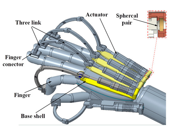
Figure 1.
CAD model of five-degree exoskeleton force feedback glove.
2.1. Transmission Structure
Each finger, excluding the thumb, is composed of three bones (proximal phalanx (PP), middle phalanx (MP), and distal phalanx (DP)) and three joints. Inspired by the mechanism of human fingers, this study designed a three-linkage transmission structure. As shown in Figure 2, the three-link transmission unit comprises three curved links connected to each other via hinges, and the ends of the linkages are connected to the actuator and the fingertip, respectively, ensuring smooth force transmission. During working, the first connecting Link1 rotates around point A, causing the motor to move relative to the base plate; thus, the force-sensing side of the linear actuator is connected to the base plate by a spherical joint, and the base plate is attached to the back of the hand with Velcro.
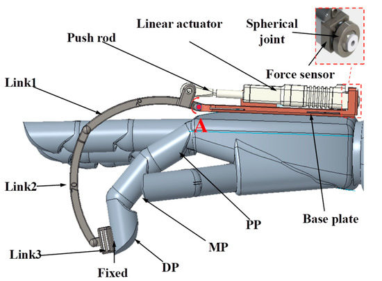
Figure 2.
Transmission structure unit of the force feedback glove.
According to the research by Kapandji et al. [25], the axes of human fingers are non-standard orthogonal to the sagittal plane, and the surface of the human finger bending motion is a curved surface since the relative directions of the finger joint axes are not perfectly parallel. A simple rigid connection is unsuitable because the joint-axis misalignment between the finger and the glove mechanism can generate an uncomfortable tangential force on the user’s fingertip. As a result, the five transmission structure units are connected with bandages instead of rigid connections, allowing the finger to bend in the direction of abduction/adduction freely while minimizing uncomfortable forces.
The length of the links is optimized based on anthropomorphic data [26] and simulation analysis, adhering to the following optimization criteria: the linear actuator motion range is 16 mm, and the length of the links should ensure that (1) the working space of the exoskeleton glove matches the finger’s movement space; (2) to prevent collisions, the links should not interfere with the movement of the finger; and (3) the limit state of the motor is close to the limit state of the finger extension. Table 2 lists the optimized dimensions of each finger link.
Table 2.
Length of links for different fingers.
Three-dimensional printing technology was employed to fabricate the components, and a robust tough resin with a bending strength of 38–56 Mpa was selected as the material to achieve high structural stiffness and reduced mass. Furthermore, the optimized dimensions also ensure the safety of the force feedback gloves. Since the linear actuator has a limited range, the limit state of the motor should be close to the limit state of finger extension but not exceed it, thus preventing potential damage to the hand during the transition of the motor stretch. Even if an accidental failure of the linear motor occurs, it would not cause serious mechanical injury to the finger. The physical view of the glove in extreme bending/extension shown in Figure 3 verifies its safety.
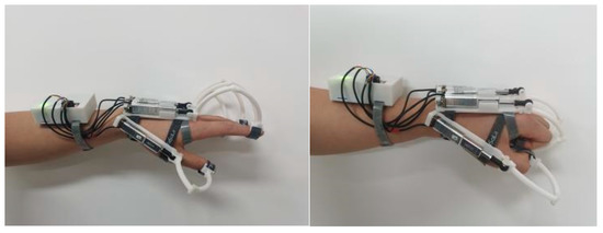
Figure 3.
Physical view of the glove in extreme bending/extension.
2.2. Kinematic and Workspace Analysis
For each force feedback unit, the exoskeleton and the human finger can be modeled as a six-bar linkage mechanism. As shown in Figure 4, the base plate is solidly connected to the hand, representing the ground. Each human finger consists of three links, as does the exoskeleton. Both the end link of the mechanism and the fingertip are attached with Velcro, so there are six links in total (one ground link, three finger links, and two exoskeleton links) and six revolute pairs.
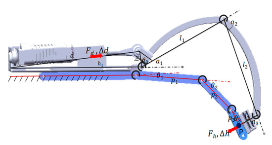
Figure 4.
Kinematic diagram of the single exoskeleton glove unit.
According to Grubler’s formula, the degrees of freedom (DOF) of this unit can be calculated using (1).
where n is the number of connecting links; is the number of lower pairs; and is the number of higher pairs. Because the number of DOF of the mechanism is two, the mechanism allows any arbitrary movement of the fingertip in the flexion–extension plane.
When the motor moves along the red axis in Figure 4, it drives the end of the force feedback glove in the red direction. The relationships between the fingertip position P, the finger joint angle, and the exoskeleton joint angle are:
where are the finger joint angles; are the exoskeleton joint angles, respectively; is the length of the exoskeleton linkage; and is the length of the fingertip.
The relationship between the exoskeleton joint angle and the motor length is
where represents the length of the linear motor; and are the designed parameters that represent the length of the base plate, the length between the pivot point and the force transmission point, and the inherent angle between the force transmission link and connecting link 1, respectively.
The relationship between the exoskeleton joint angle and the finger joint angle is as follows:
where:
Therefore, if the joint angle of the human finger is known, the joint angle of the exoskeleton and the length of the linear motor can be calculated with (5)–(6). Conversely, if the length of the linear motor and the joint angle of the exoskeleton are known, the current joint angle of the human finger can be determined.
Additionally, this study analyzed the workspace performance through simulation. The MATLAB Robotics Toolbox [27] was used to simulate the movement of both the human hand and the haptic glove. Each finger is modeled as a serial kinematically rigid robot using the standard Denavit–Hartenberg (DH) notation. According to references [28,29,30], the anthropometric data, including the average length of the index finger knuckle and the minimum and maximum joint angles, are presented in Table 3.
Table 3.
Parameters of the finger and the exoskeleton.
With this information, the 2D motion space of the single finger and the exoskeleton structure is obtained. As depicted in Figure 5, the orange point clouds represent the exoskeleton motion points, and the motion space of the human finger is depicted with blue points. The simulation result demonstrates that the designed mechanism is capable of covering a substantial portion of the operational workspace of the finger. This conclusion is verified by the physical picture of the wearer in different bending states (Figure 6). Moreover, the limitation in achieving the tight grip position helps prevent potential harm to the wearer’s finger joints in case of motor malfunction. The motion spaces of the other fingers are consistent with this pattern.
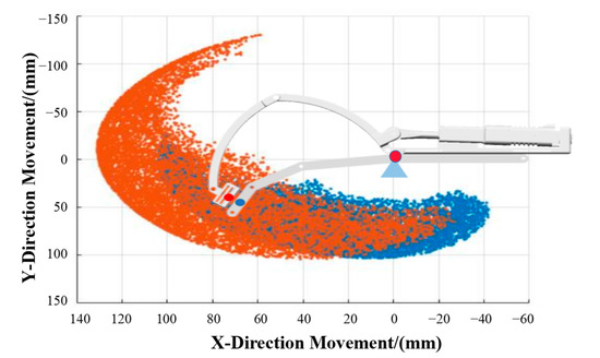
Figure 5.
Workspace simulation of the human finger and the exoskeleton.
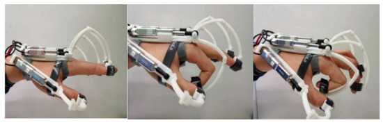
Figure 6.
Exoskeleton gloves in different bending states.
2.3. Force Sensing and Transmission
Real-time measurement of the feedback force is necessary for closed-loop force control. Nevertheless, traditional fingertip force sensors might not be well suited for exoskeleton systems. The limitations of this approach include: (1) The fingertip force sensor requires bulky fixtures to attach to the fingers. Moreover, one fingertip force sensor requires at least three communication wires, resulting in a confusing structure and lack of stability; (2) The force sensor needs to be in close contact with the fingertips; excessive mounting preload can produce severe uncomfortable compression and even cause insufficient blood supply to the fingers. A small mounting preload can cause the force sensor to slip or even to make poor contact with the force sensor, resulting in serious dynamic measurement errors. In addition, the mounting preload is not fixed for each wear, which further reduces the measurement accuracy and stability of the force sensor and leads to oscillation in the response of the force closed-loop control algorithm. For these reasons, mounting the force sensor directly on the fingertip dose not facilitate precise force measurement. In this design, an indirect force measurement method was utilized. As Figure 7 shows, a compact force sensor, enabling force detection within a range of [−50 N, 50 N] with a resolution of 1 N (Inspire robot Inc., Beijing, China.), was connected to the motor’s end to measure the drive force, The rendering of the gripping force is achieved through the designed three-link structure, which transfers the actuator-generated driving force to the finger.
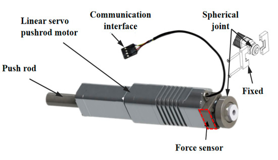
Figure 7.
Linear servo with force sensing.
Below, we analyze the relationship between the driving force and the fingertip force, which focuses on the device’s ability to transmit the desired force to the fingertips, and to determine whether there is a fixed positive correlation.
Since the weight of the links is relatively small compared to the transmitted force, the weight factor of the exoskeleton can be neglected. Furthermore, the gradual rate of change in the user’s finger movements implies that the acceleration of each link during finger motion can be set aside. For the reasons listed above, the force transmission can be simplified as a quasi-static force analysis.
As shown in Figure 8, is the pulling force generated by the actuator and is the normal force applied to the fingertip. According to the static equilibrium equations, the relationship between the driving force and the effective orthogonal decomposition force of link 2 on link 1 is as follows:
where:
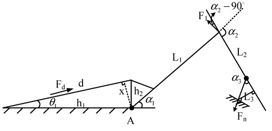
Figure 8.
Force transfer analysis diagram.
The static force analysis of link 2 is a s follows:
The relationship between the force perceived at the fingertip and the driving force of the motor can be obtained with (10) the following:
Therefore, the driving force and finger force are positively correlated.
2.4. Electrical Design
In terms of electrical design, the focus was on designing compact interface circuit boards to ensure portability and durability. As depicted in Figure 9, the electrical system comprises a microcontroller, a wireless communication module, five channels of A/D acquisition (for fingertip pressure sensors), five linear servo motor communication channels, and a rechargeable battery.
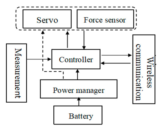
Figure 9.
Block diagram of the electrical system.
The controller communicates with the actuator by means of a bus with a maximum frequency of 921,600 bps. Actuators were distinguished by assigning different ID codes, enabling the controller to manage up to 254 motors on one communication channel.
The Arduino microcontroller (Nano), a miniaturized high-performance microprocessor, was applied as the control module. The processor performs the following functions: (1) measuring the driving force and the drive position of the actuator; (2) sending commands to the actuator to control the force applied to the fingertips; (3) communicating with the teleoperated master unit to control the movement of the remote bionic mechanical hand; (4) communicating with the teleoperation master unit to obtain the desired feedback force back for the operator.
The microcontroller operates at a frequency of 16 MHz. Communication between the glove and the master is realized through a wireless Bluetooth module, which transmits data at an update rate of 9600 Hz and communicates with the linear actuator at a frequency of 128,000 Hz.
3. Control System
Limited by the drawbacks of fingertip force sensors discussed in Section 2.3, currently, EFFGs have difficulty in achieving the measurement of feedback forces. In this study, an exoskeleton structure was designed with a driving force sensor installed at the end of the motor. The structure enables indirect acquisition of the actual feedback force exerted on the finger through the force transfer mechanism. In other words, the feedback force of the fingertip can be analytically calculated by (7)–(10). However, the results of the analysis and related research indicate that the parameters related to the force transfer function such as the lengths of each finger phalange (p1, p2, and p3) vary for each individual, making theoretical calculations unsuitable for direct application. As stated in (7)–(10), the transfer relationship between the driving force and the fingertip sensing force is non-linear, but positively correlated at a specified location. In this study, an indirect closed-loop force feedback method is proposed for haptic interaction in isomorphic systems.
3.1. Architecture of Isomorphic Teleoperation Systems
As depicted in Figure 10, the designed isomorphic teleoperation systems comprise a force feedback glove and a humanoid hand. The humanoid hand is a commercially available manipulator, with a similar mechanism to the exoskeleton glove, featuring five driving DOFs. The driving force can be measured indirectly through the driving current. When the user wears the glove, assisted by vision, the user controls the extension or bending of the fingers by driving the movement of the exoskeleton glove; therefore, the movement of the slave robot is controlled based on the measured length of the glove’s motor actuator. When the slave manipulator makes contact with an object, the gripping force exerted by the remote actuator is transmitted to the operator through the exoskeleton glove.
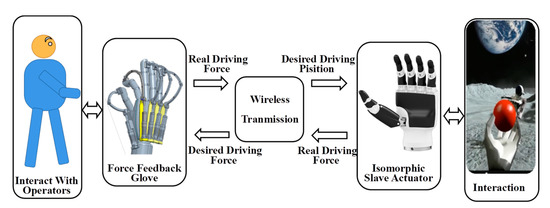
Figure 10.
Schematic of isomorphic teleoperation systems.
Figure 11 presents the control diagram for the isomorphic teleoperation system. In the free workspace, the desired force of the impedance controller is set to 0. The exoskeleton glove extends or flexes under the traction of human fingers, and the motion of the slave hand is controlled by the bending position of the exoskeleton glove (the code value of the motor). When the slave manipulator is in contact with an object, the desired force and desired position (Fd, Xd) of the controller are set to the driving force and driving position (Fs, Xs) applied by the remote actuator. In other words, the driving force applied to the fingers by the exoskeleton glove is equivalent to the driving force applied to the object by the slave actuator. This provides the operator with an immersive gripping sensation and enables more intuitive and secure control of the robot.
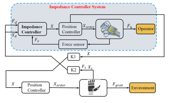
Figure 11.
Teleoperation control system.
3.2. Modeling of Impedance Controller
The core of the control system is achieving a smooth control method for the required driving force. According to the previous related studies [23,24], the response characteristics of the PID can cause sudden rotation of the motor at the moment of contact with an object, causing a shock sensation for the operator’s hand. Therefore, Y. Park designed a transition balance strategy based on scaling factors to achieve smooth transitions from free mode to interactive mode, but with a decreased response speed [11]. As a compliant control algorithm, in this study, the impedance control method is employed for the control of the exoskeleton force feedback as it offers both flexibility and accurate tracking of the desired forces [31].
Impedance control can be classified into two types: force-based and position-based impedance control. The former relies on an accurate dynamics model, while the latter functions by inputting a desired contact force and mapping it to the desired position of the target. In this study, position-based impedance control was selected, as the linear motor employed is capable of achieving precise position control.
The impedance controller model is a second-order model [32], mathematically represented as follows:
where are the actual driving position, driving velocity, and acceleration of the EFFG; denote the desired driving position, driving velocity, and acceleration; and indicates the difference between the desired driving force of the exoskeleton and the real driving force measured by the force sensor.
In the control process of exoskeleton gloves, the desired driving force and stiffness in the free workspace are set to zero, enabling the human finger to move freely. The position of the slave actuator tracks the driving position of the exoskeleton, which is controlled by the operator. In the interaction mode, the desired driving force of EFFG is set to match the driving force applied by the slave actuator, while the desired position is set to the driving position when the slave actuator is in contact. This enables the operator to feel the gripping force applied by the slave actuator.
4. Experiments
This section first summarizes the key physical parameters of the EFFG prototype. Subsequently, a test bench is designed to quantitatively assess the performance through a series of experiments primarily focusing on transparency in free and constrained spaces. Finally, the overall performance is tested to evaluate the characteristics of the designed control method. The same control method was applied to all five fingers, with experiments conducted using the operator’s index finger as an example.
4.1. Physical Characteristics
The total weight of the designed EFFG prototype is 278 g, including the battery. As a wireless wearable force feedback device, it offers enhanced wearing performance. The theoretical power consumption is 2.1 W, with a battery capacity of 7.4 V/1500 mAh and an experimental working time of 25 min under no load; the working time under load is about 15 min. The main physical characteristics of the force feedback gloves are presented in Table 4.
Table 4.
Performance data for exoskeleton force feedback gloves.
Compared with similar mechanical exoskeleton systems proposed in recent years (Table 1), it can be concluded that our designed EFFG is lightweight. Its wireless design eliminates the need for cumbersome transmission lines, resulting in enhanced wearability. Furthermore, the EFFG enables the detection of driving force and improves the accuracy of the feedback force.
4.2. Performance Evaluation
4.2.1. System Setup
To assess the performance of the force feedback glove, a wearable measurement system was designed. As shown in Figure 12, an industrial force sensor (15 mm (d) × 9 mm (h) ZNLBM-IX-10 KG, CHINO sensor, 0.1%) was fixed to the lower surface of the finger to measure the fingertip force transmitted by the exoskeleton. The force signal was transmitted through a signal collector and displayed on a computer. The force sensor was powered by a 12 V DC power supply. The performance of the EFFG in both simulated free and constrained spaces was evaluated.
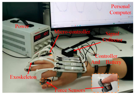
Figure 12.
The performance test platform.
4.2.2. Performance in the Free Workspace
Based on the experiment and related studies [33], the impedance parameters in the impedance controller were set to k = 0, m = 0.1, and b = 1.5, and the desired driving force of the exoskeleton was set to = 0. In an ideal free workspace performance, the operator should be able to move their fingers effortlessly. The resistance in the free working space mainly arises from the response speed of the impedance control, which is directly related to the impedance parameters. Therefore, optimizing these parameters could potentially enhance performance.
Resistance is a critical factor in determining the sensation of freedom in the workspace. In this study, the operator wore the EFFG and moved their fingers back and forth five times within a span of 30 s. As shown in Figure 13, the code 0–2000 represents the position codes of the motor, where code 0 indicates the fully extended state of the finger, and code 2000 corresponds to a fully bent state. is the force of fingertip force sensor, reflecting the force directly felt by the operator. The experimental results reveal that the preload force on the finger is about 1.2 N, and the resistance during free motion ranges from 0.4 N to 0.8 N. These results demonstrate that the EFFG controller designed based on impedance theory exhibits relatively low resistance in the free workspace, enabling the finger to move freely.
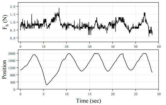
Figure 13.
The movement position and corresponding fingertip force during finger free movement in free workspace.
The measured finger force () not being zero in the free workspace is reasonable, as the function of the impedance control is to map the error between the measured driving force and the desired driving force to the desired position, thereby enabling the finger to move freely.
4.2.3. Performance in the Constrained Workspace
The control method based on impedance theory in a constrained workspace enables the rendering of feedback force. The real-time driving force exerted by the motor on the target object is used as the desired driving force at the fingertip, and the actual driving position of the manipulator is taken as the desired position for impedance control.
The measured force of the force sensor represents the feedback force applied to the fingertip. In the experiment, the finger initially remains stationary. It is set such that the object is grasped with a motor driving force of 30 N at T = 4 s.
The force measured by the force sensor is shown in Figure 14, where represents the measured driving force of the motor and represents the measured fingertip force, the red dotted line indicates the beginning and end of the response phase. The initial pressure on the finger reflects the pre-tensioning of the bandage, with a value of approximately 1.1 N. According to the response curve, the response time of the driving force to reach the first peak is 0.36 s, and the response time of the finger to feel the steady feedback force is 0.48 s. Moreover, it can be observed that the driving force of the linear motors responds rapidly to the target force without significant fluctuations; the operator would not feel a big vibration due to the sudden rotation of the motor, fulfilling the requirement for force tracking.
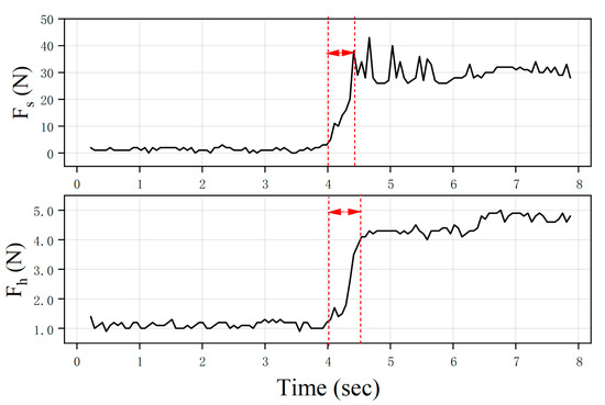
Figure 14.
The driving force and corresponding fingertip force during the recreating of hand forces in a constrained workspace.
4.2.4. Performance of Overall Motion
In this evaluation scenario, the EFFG is worn on the finger and kept stationary at the beginning. Before T1, the operator moves their fingers freely, and the resistance force on the finger at this time is around 0.5 N, consistent with the value observed in the free workspace experiment. At T1, a desired driving force of 30 N is set to simulate the force feedback after gripping an object.
The measured driving force () and finger pressure () curve depicted in Figure 15 demonstrates that due to the adoption of impedance control, the driver can respond rapidly to the target force without causing substantial jumps. The operator does not experience the sudden shock sensation caused by the motor’s abrupt rotation. However, unwanted chattering is present in the feedback force, primarily due to the jitter of fingers while overcoming the resistance force, reducing the measurement accuracy of the fingertip. This is also the reason for the absence of fingertip force sensors, as described before. The position data show some variation during the response period, which is reasonable as the glove provides the required force feedback by pulling the finger through the motor.
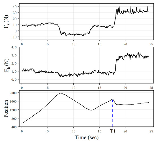
Figure 15.
Force response curve with overall motion.
4.2.5. Comparison with PID Control Methods
As a classical closed-loop control method, the PID control algorithm has the advantages of fast response and ease of use, and it has been widely used in industry, medicine, and other fields. Therefore, this paper explores the performance of the PID control algorithm in achieving feedback force presentation in the constraint workspace and compares its performance with that of the impedance control algorithm.
Consistent with the experiments of evaluating constrained space performance based on impedance control, in the initial stage, the finger is in a relaxed state, and the initial value of represents the preload force of the sensor, which is approximately 1.87 N. At T = 2.7 s, it is assumed that the motor of the slave actuator grasps the object with a driving force of 30 N. As shown in Figure 16, the motor reaches the required driving force in 0.58 s. However, due to the sudden rotation of the motor, the feedback force felt by the finger rapidly increases within 0.32 s, with an overshoot of about 15%. In comparison, the fingertip achieves the desired feedback force within 0.48 s using the impedance control method, demonstrating a smoother response with an overshot not exceeding 5%. Additionally, periodic oscillation can be observed in the regulation process to achieve the desired driving force in PID control. This is reasonable, as PID achieves regulation based on the error with the desired force. However, the error cannot decay due to the effect of physiological jitter in the human finger.
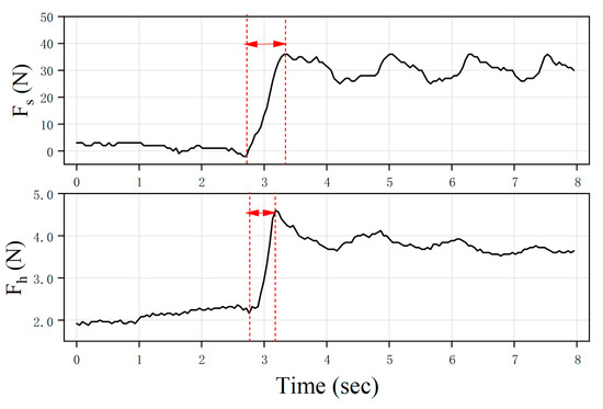
Figure 16.
The driving force and finger force response characteristic curve with PID control methods.
5. Discussion and Future Work
This paper presents the design and experimental evaluation of a new haptic glove. Based on the performance requirements outlined in Section 1, the main contributions and novelty of this glove are summarized as follows:
- (1)
- Size and weight—The entire system, including the glove skeleton, battery, and actuator unit, weighs only 278 g. In addition to being lightweight, it is also portable, wireless, and self-contained, with no need for additional external devices or complex transmission lines. This improves the sense of wearing and flexibility of gloves;
- (2)
- Safety and large workspace—The three joints of each link are driven by a single actuator unit through a push–pull cable mechanism. The designed transfer mechanism is capable of covering a huge workspace of the fingers. Moreover, the limit state of the motor is close to the limit state of finger extension, which helps prevent potential harm to the wearer’s finger joints in the event of motor malfunction, even if there is an accidental failure of the linear motor;
- (3)
- Flexible and fast dynamic force response—A compact miniature force sensor is mounted at the end of the motor to measure driving force. Based on the measurement of driving force, a closed-loop force control based on the impedance algorithm is designed. Compared to the PID control algorithm, the designed impedance control algorithm exhibits more flexible dynamic force response and avoids sudden motor movement at the boundaries of different work strategies.
Compared to commercial and other force feedback gloves [17,18,19,20,21,22,23,24,25], the proposed glove mechanism has the following disadvantages: (1) Lack of soft wearability—The glove is mounted on the finger through Velcro, and each finger needs to be fixed separately, resulting in a complicated wearing process. Furthermore, the finger is connected to the rigid linkage structure directly, resulting in an uncomfortable feeling; (2) Slow response speed—While the response speed under constrained workspace has increased by more than 50% compared to that reported in the literature [11], the response speed remains relatively low, especially in the free workspace. The adopted motor’s movement speed is 50 mm/s, which enables the finger to fully extend/contract 180 times in one minute, meeting the requirement of fast hand movements. However, the control algorithm requires further optimization to enhance movement speed and the feedback force resolution; (3) Limited maximum feedback force—A simple three-link structure was designed, and when the force is larger, the link will produce bending deformation, limiting the maximum feedback force.
In future research, the control algorithm will be further refined to focus on enhancing the response speed and reducing the obstruction force in the free workspace; for example, by further optimizing the impedance parameters or using adaptive impedance control. Additional investigation into the mapping relationship between the glove’s driving force and the driving force of the slave actuator is warranted. Moreover, the proposed device will be integrated with the haptic feedback device [34] developed in our lab to further augment immersion. Furthermore, performance evaluations will be conducted on our wearable locator-based teleoperation system with various operators.
6. Conclusions
This paper presents the design and experimental evaluation of a new lightweight five-finger exoskeleton glove. The design employs a lightweight three-link structure to achieve stable and reliable force transmission. The mechanism has a total mass of 278 g for all five fingers and features a completely wireless system, as well as a motor integrated with a force sensor. This allows for real-time driving force measurement in closed-loop force control, improving force feedback accuracy. The analysis of the workspace illustrates that the design structure can achieve a large fingertip working space without motion interference. Relevant experiments show that the mean obstruction force during free motion is approximately 0.5 N. The designed impedance controller, based on driving force, can achieve smooth feedback force control without huge sudden motor movement at the boundaries of different work strategies.
Author Contributions
Conceptualization, S.P., X.C. and P.W.; methodology, S.P. and M.Y.; algorithm, S.P., X.G. and M.Y.; experiments, S.P. and M.Y.; research, S.P. and X.C.; writing—original draft preparation, S.P., M.Y. and X.C.; writing—review and editing, S.P., M.Y., X.C. and P.W.; supervision, X.C. and P.W. All authors have read and agreed to the published version of the manuscript.
Funding
This research was funded by the National Natural Science Foundation of China (Nos. 51905530, 51901244, 52005494, and 91748209) and Program 173.
Institutional Review Board Statement
Not applicable.
Informed Consent Statement
Not applicable.
Data Availability Statement
Not applicable.
Conflicts of Interest
The authors declare no conflict of interest.
References
- Miyazaki, R.; Hirose, K.; Ishikawa, Y.; Kanno, T.; Kawashima, K. A Master–Slave Integrated Surgical Robot With Active Motion Transformation Using Wrist Axis. IEEE/ASME Trans. Mechatron. 2018, 23, 1215–1225. [Google Scholar] [CrossRef]
- Lin, Y.; Zhao, H.; Zhang, Y.; Ding, H. A Data-Driven Motion Mapping Method for Space Teleoperation of Kinematically Dissimilar Master/Slave Robots. In Proceedings of the 2018 IEEE International Conference on Robotics and Biomimetics (ROBIO), Kuala Lumpur, Malaysia, 12–15 December 2018; pp. 862–867. [Google Scholar]
- Pacchierotti, C.; Sinclair, S.; Solazzi, M.; Frisoli, A.; Hayward, V.; Prattichizzo, D. Wearable Haptic Systems for the Fingertip and the Hand: Taxonomy, Review, and Perspectives. IEEE Trans. Haptics 2017, 10, 580–600. [Google Scholar] [CrossRef] [PubMed]
- Blake, J.; Gurocak, H.B. Haptic Glove with MR Brakes for Virtual Reality. IEEE/ASME Trans. Mechatron. 2009, 14, 606–615. [Google Scholar] [CrossRef]
- Cho, S.K.; Jin, H.Z.; Lee, J.M.; Yao, B. Teleoperation of a Mobile Robot Using a Force-Reflection Joystick with Sensing Mechanism of Rotating Magnetic Field. IEEE/ASME Trans. Mechatron. 2010, 15, 17–26. [Google Scholar] [CrossRef]
- Lee, S.; Sukhatme, G.S.; Kim, G.J.; Park, C.-M. Haptic Control of a Mobile Robot: A User Study. In Proceedings of the IEEE/RSJ International Conference on Intelligent Robots and Systems, Lausanne, Switzerland, 30 September–4 October 2002; Volume 3, pp. 2867–2874. [Google Scholar]
- Chen, X.; Agrawal, S.K. Assisting Versus Repelling Force-Feedback for Learning of a Line Following Task in a Wheelchair. IEEE Trans. Neural Syst. Rehabil. Eng. 2013, 21, 959–968. [Google Scholar] [CrossRef]
- Bolopion, A.; Régnier, S. A Review of Haptic Feedback Teleoperation Systems for Micromanipulation and Microassembly. IEEE Trans. Autom. Sci. Eng. 2013, 10, 496–502. [Google Scholar] [CrossRef]
- Coles, T.R.; Meglan, D.; John, N.W. The Role of Haptics in Medical Training Simulators: A Survey of the State of the Art. IEEE Trans. Haptics 2011, 4, 51–66. [Google Scholar] [CrossRef]
- Ferre, M.; Galiana, I.; Wirz, R.; Tuttle, N. Haptic Device for Capturing and Simulating Hand Manipulation Rehabilitation. IEEE/ASME Trans. Mechatron. 2011, 16, 808–815. [Google Scholar] [CrossRef]
- Park, Y.; Jo, I.; Lee, J.; Bae, J. A Dual-Cable Hand Exoskeleton System for Virtual Reality. Mechatronics 2018, 49, 177–186. [Google Scholar] [CrossRef]
- Richard, C.; Cutkosky, M.R. Contact Force Perception with an Ungrounded Haptic Interface. In Proceedings of the ASME International Mechanical Engineering Congress and Exposition, American Society of Mechanical Engineers. Dallas, TX, USA, 16–21 November 1997; Volume 18244, pp. 181–187. [Google Scholar]
- Vulliez, M.; Zeghloul, S.; Khatib, O. Design Strategy and Issues of the Delthaptic, a New 6-DOF Parallel Haptic Device. Mech. Mach. Theory 2018, 128, 395–411. [Google Scholar] [CrossRef]
- Herbin, P.; Pajor, M. ExoArm 7-DOF (Interactive 7-DOF Motion Controller of the Operator Arm) Master Device for Control of Loading Crane. In Proceedings of the Advances in Manufacturing; Hamrol, A., Ciszak, O., Legutko, S., Jurczyk, M., Eds.; Springer International Publishing: Cham, Switzerland, 2018; pp. 439–449. [Google Scholar]
- Qin, H.; Song, A.; Liu, Y.; Jiang, G.; Zhou, B. Design and Calibration of a New 6 DOF Haptic Device. Sensors 2015, 15, 31293–31313. [Google Scholar] [CrossRef] [PubMed]
- Perret, J.; Parent, Q.; Giudicelli, B. HGlove: A Wearable Force-Feedback Device for the Hand. In Proceedings of the 14th Annual EuroVR Conference, Laval, France, 12–14 December 2017. [Google Scholar]
- Guo, Y.; Yang, X.; Wang, H.; Zhang, Y.; Xu, W.; Wang, D. Five-Fingered Passive Force Feedback Glove Using a Variable Ratio Lever Mechanism. Actuators 2021, 10, 96. [Google Scholar] [CrossRef]
- Wang, D.; Wang, Y.; Pang, J.; Wang, Z.; Zi, B. Development and Control of an MR Brake-Based Passive Force Feedback Data Glove. IEEE Access 2019, 7, 172477–172488. [Google Scholar] [CrossRef]
- Aiple, M.; Schiele, A. Pushing the Limits of the CyberGraspTM for Haptic Rendering. In Proceedings of the 2013 IEEE International Conference on Robotics and Automation, Karlsruhe, Germany, 6–10 May 2013; pp. 3541–3546. [Google Scholar]
- Ben-Tzvi, P.; Ma, Z. Sensing and Force-Feedback Exoskeleton (SAFE) Robotic Glove. IEEE Trans. Neural Syst. Rehabil. Eng. 2015, 23, 992–1002. [Google Scholar] [CrossRef]
- Zheng, Y.; Wang, D.; Wang, Z.; Zhang, Y.; Zhang, Y.; Xu, W. Design of a Lightweight Force-Feedback Glove with a Large Workspace. Engineering 2018, 4, 869–880. [Google Scholar] [CrossRef]
- Wang, Z.; Wang, D.; Zhang, Y.; Liu, J.; Wen, L.; Xu, W.; Zhang, Y. A Three-Fingered Force Feedback Glove Using Fiber-Reinforced Soft Bending Actuators. IEEE Trans. Ind. Electron. 2020, 67, 7681–7690. [Google Scholar] [CrossRef]
- Sarakoglou, I.; Brygo, A.; Mazzanti, D.; Hernandez, N.G.; Caldwell, D.G.; Tsagarakis, N.G. HEXOTRAC: A Highly under-Actuated Hand Exoskeleton for Finger Tracking and Force Feedback. In Proceedings of the 2016 IEEE/RSJ International Conference on Intelligent Robots and Systems (IROS), Daejeon, Korea, 9–14 October 2016; pp. 1033–1040. [Google Scholar]
- Le, D.T.G.; Nguyen, L. An Efficient Force-Feedback Hand Exoskeleton for Haptic Applications. Int. J. Intell. Robot Appl. 2021, 5, 395–409. [Google Scholar] [CrossRef]
- Kapandji, I.A. The Physiology of the Joints, Volume I., Upper Limb. Am. J. Phys. Med. Rehabil. 1971, 50, 96. [Google Scholar]
- Ma, Z.; Ben-Tzvi, P. Design and Optimization of a Five-Finger Haptic Glove Mechanism. J. Mech. Robot. 2015, 7, 041008. [Google Scholar] [CrossRef]
- Robotics, Vision and Control. Fundamental Algorithms in MATLAB | Emerald Insight. Available online: https://www.emerald.com/insight/content/doi/10.1108/ir.2012.04939faa.005/full/html (accessed on 6 December 2022).
- Freivalds, A. Biomechanics of the Upper Limbs: Mechanics, Modeling and Musculoskeletal Injuries; CRC Press: Boca Raton, FL, USA, 2011. [Google Scholar]
- Churchill, E.; McConville, J.T. Sampling and Data Gathering Strategies for Future USAF Anthropometry. 1976. [Google Scholar]
- Houbec, K.; Tillman, B.; Connolly, J. Human Factors, Habitability and Environmental Health and the Human Integration Design Handbook. In Proceedings of the Industrial Engineering Research Conference (IERC), Cancun, Mexico, 5–9 June 2010. [Google Scholar]
- Li, J.; Wang, Y.; Liu, Z.; Jing, X.; Hu, C. A New Recursive Composite Adaptive Controller for Robot Manipulators. Space Sci. Technol. 2021, 2021, 9801421. [Google Scholar] [CrossRef]
- Qi, Y.; Jia, Y.; Zhao, B.; Zhong, R. Impedance Control of Space Manipulator Based on Improved Neural Network. Chinses Space Science and Technology 2022, 42, 82. [Google Scholar] [CrossRef]
- Song, P.; Yu, Y.; Zhang, X. A Tutorial Survey and Comparison of Impedance Control on Robotic Manipulation. Robotica 2019, 37, 801–836. [Google Scholar] [CrossRef]
- Yu, M.; Cheng, X.; Peng, S.; Cao, Y.; Lu, Y.; Li, B.; Feng, X.; Zhang, Y.; Wang, H.; Jiao, Z.; et al. A Self-Sensing Soft Pneumatic Actuator with Closed-Loop Control for Haptic Feedback Wearable Devices. Mater. Des. 2022, 223, 111149. [Google Scholar] [CrossRef]


Disclaimer/Publisher’s Note: The statements, opinions and data contained in all publications are solely those of the individual author(s) and contributor(s) and not of MDPI and/or the editor(s). MDPI and/or the editor(s) disclaim responsibility for any injury to people or property resulting from any ideas, methods, instructions or products referred to in the content. |
© 2023 by the authors. Licensee MDPI, Basel, Switzerland. This article is an open access article distributed under the terms and conditions of the Creative Commons Attribution (CC BY) license (https://creativecommons.org/licenses/by/4.0/).