Article

A Novel High-Voltage-Cable Stripping Robot

College of Mechanical & Electrical Engineering, Hohai University, Changzhou 213022, China
*
Author to whom correspondence should be addressed.
Actuators 2023, 12(5), 201; https://doi.org/10.3390/act12050201
Submission received: 4 April 2023 / Revised: 6 May 2023 / Accepted: 11 May 2023 / Published: 12 May 2023

Abstract

:
One of the primary duties in the regular maintenance of electrical distribution networks is the cable stripping operation. In this paper, a unique robot is proposed to overcome drawbacks of the conventional manual operation of cable stripping, such as poor efficiency, low safety, and high labor intensity. This innovative cable-stripping robot is made up of a rotating mechanism, a cable gripping component, and a cutter feeding mechanism that can be adjusted depending on the working environment and workload. The robot’s motors, sensors, main control chip, and wireless communication modules are all carefully selected. A carefully designed cascade controller is created for the robot in an effort to lessen damage to the aluminum core. While the outside location loop uses the PID algorithm, the inner speed control loop uses fuzzy PID. The robot can successfully accomplish cable stripping work and demonstrates its potential to reduce labor intensity. Cable stripping experiments are conducted to validate the effect of the robot and its controller.

1. Introduction

One of the most direct and efficient ways to cut down on outages and increase the dependability and quality of the electrical power supply is through routine maintenance of the distribution network [1,2]. The demand for live work maintenance is rising, along with the amount of repair operations on the distribution network, which is crucial infrastructure for safeguarding the national economy and peoples’ livelihoods [3]. Currently, electrically disconnecting, stripping, wiring, and connecting the lead cable are the key live working responsibilities. The human sawing process used in traditional cable stripping, however, has a number of drawbacks, including low safety, high labor intensity, and low levels of mechanization.
Japanese researchers have been working on different distribution network operation robots since the 1980s. The most well-known of these was the first-generation master-slave-mode robot “Phase I,” a double-arm manipulator mounted on a mobile crane [4]. The robot increased productivity while also lightening the operator’s hard workload. Soon after, Kyushu Electric Power Group successfully produced “Phase II” and “Phase III” [5,6], the second and third generations of power operating robots. On the back of “Phase I”, “Phase II”, and “Phase III”, a vision system was added. The insulated bucket truck was used in conjunction with a remote control system for a hydraulically driven robot arm created by the U.S. Electric Power Sector. The distribution network break could be realized by the robot arm, and the lead wire could be connected, but the stripping effect and distribution quality were not good [7]. An electric work robot with a wireless operator that could send commands and receive working data was created in Spain in the early 1990s [8]. An agricultural distribution network robot with the ability to adapt to any terrain was developed by Yuliang Zhao et al., and its specialized tools could operate in confined spaces [9]. Wu Han [10] created an automatic stripping system for hot wire connections that included a locking and stripping element, a supporting component, a guiding mechanism, and a drive subsystem. A high-voltage live working robot system with two components—the robot subsystem and the operator platform subsystem—was created by T. Lei et al. [11]. A robotic distributed operation terminal energized installing tool was created by Jinlu Zhang et al. [12], and primarily fulfilled the functions of clamping pierce pliers, threading/stripping/clamping branches, and other independent operations. A wire-breaking distribution network electrical robot that could perform replacement and disconnect operations was designed by Yu Yan et al. [13], but no actual prototype was created for validation. An auxiliary robotic arm that could perform tasks including cutting wires, removing insulation, and joining cables was proposed by Hiroaki Seki et al. [14]. The robotic arm, however, was too hefty to move on its own. For 10 kV overhead lines, JiaBo Feng et al. developed an automatic energized line maintenance robot [15] that could do tasks such as wire stripping, voltage sensing, installing wire clips, and cutting off the lead wire. A complicated dual-armed robot system for grid maintenance was created by Liming Zhang et al. [16], and included an operator module, a reference board platform module, an insulated cover, and a set of dual-collaborative UR-10 manipulators.
A thorough investigation of the created cable-stripping tools exposes a number of issues, including an excessively complex robot structure, insulating layer residue retention, subpar stripping quality, and a low level of automation. Since they are integrated with the connector and cannot work independently, the wire-stripping tools developed in the existing literature are subsystems of the entire power operation robot rather than a standalone component. Additionally, there are no sensors built into the wire-stripping devices mentioned in the literature that can identify cables and cable cores. Instead, based on the cable model, a fixed thickness of the insulation skin is set, which may result in the cable core being cut by a blade. The wire stripping effect is in fact not perfect, and the cable core frequently sustains severe damage, according to earlier literature on the work effect of wire-stripping instruments.
This study suggests a unique 10 kV distribution network cable-stripping robot and investigates its management scheme in order to accomplish the function of active cable insulation skin stripping. The following is a list of the study’s primary contents.
(1) The structural plan of the automatic cable-stripping robot is created in accordance with the operational environment and design specifications, and the necessary driven torques are computed.
(2) The hardware and software layers of the control system are developed. For the robot, a cascade algorithm is developed. A PID algorithm is used in the controller’s outer loop to achieve position tracking, and a fuzzy PID algorithm is used in the inner loop to regulate the speeds of the robot’s three motors.
(3) The results of stripping experiments on 120 mm2 overhead insulated aluminum stranded cables show the robot’s capabilities. Comparing the fuzzy PID algorithm’s stripping effect to that of the standard PID algorithm further demonstrates its superiority.

2. Introduction of the Novel Cable—Stripping Robot

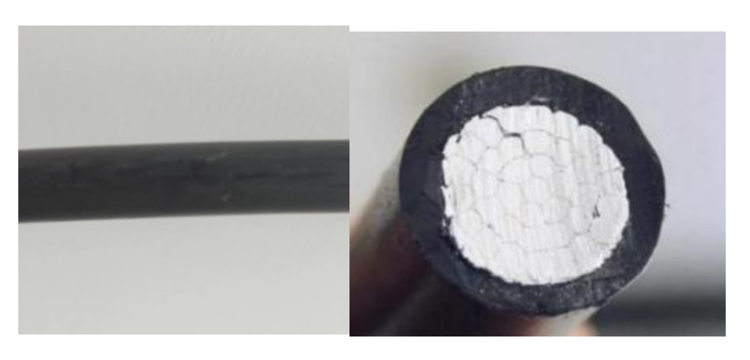
2.1. Operating Environment and Design Requirements

Power lines can be broadly categorized into two types, distribution lines and transmission lines, based on their various uses [17,18,19]. As seen in Figure 1, distribution lines, which typically include 380 V low voltage lines and 10 kV lines, are utilized to distribute power directly to users [20]. Transmission lines are used to link two public substations that operate at higher voltages, often at 35 kV and above. The robot used in this study is made to automatically remove the insulation from cables with 10 kV distribution lines and overhead wires made of 120 mm2 aluminum strands.
The following specifications are presented for the 10 kV distribution network cable stripping robot taking into account working conditions and features of the cable-peeling operation.
(1) The robot’s mass shouldn’t be more than 5 kg, and it should be portable and tiny in size.
(2) To outpace the typical manual speed, the insulation stripping speed should be greater than 5 cm/min.

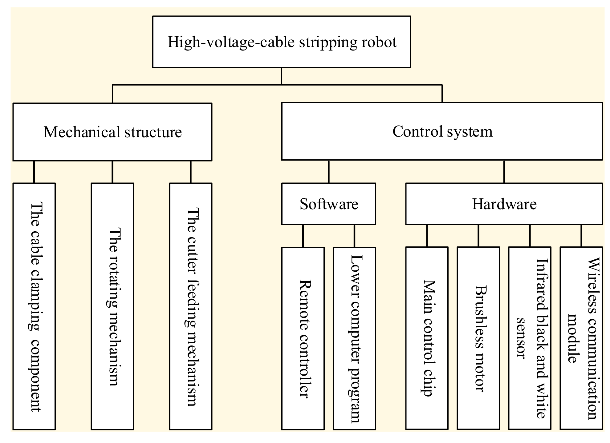
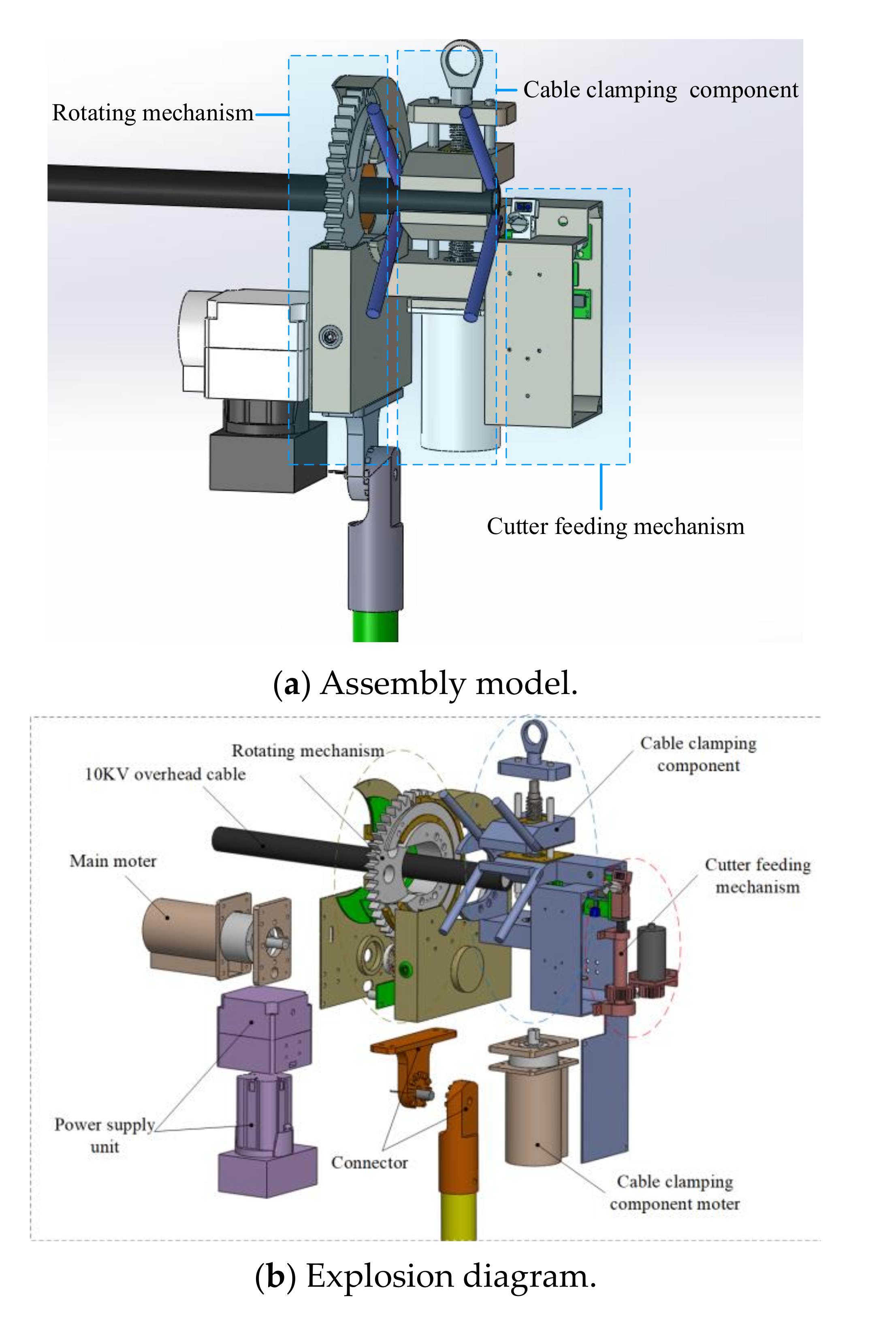
2.2. Description of the Robot Structure

A mechanical construction and control system make up the bulk of the high-voltage-cable stripping robot’s design, as shown in Figure 2. A rotating mechanism, a cable clamping component, and a cutter feeding element are the majority of the machinery’s three parts, while software and hardware comprise the control system.
Figure 3 displays the three-dimensional model of the high-voltage wire-stripping robot described in this study. The main line is clamped using the cable clamping component to stop any shaking while working. The cutter feed mechanism has a feed depth adjustment that can be made in accordance with the cable’s outer diameter and insulation thickness. The insulating skin is sliced rotationally using the revolving mechanism. The main structure of the wire stripping robot is made of an aluminum alloy, which has the benefits of being lightweight, strong, corrosion-resistant, and low density.

2.2.1. Torque Calculation of Screw Motor

The output of the screw motor torque is translated into the axial thrust and axial rotational torque of the screw in the cable clamping component. The axial torque of the screw is computed using the following formula
F = 2 π η T P
where T is the screw torque, F the screw thrust, P the screw lead, and η is the transmission efficiency.
The torque Mr, produced by the circumferential component force of the lead screw, can be calculated as follows depending on the thread lift angle λ and the lead screw’s thrust F
M r = F d 2 tan λ
The formula for calculating the friction force of the smooth rod slide rail of the lead screw at both ends of the V-type clamp is as follows
f = μ F N = μ M r L = 2 π μ η T tan λ d 2 L P
where μ is the friction coefficient, and L is the center distance between the lead screw and the smooth rod slide rail.
The following prerequisites must be met for the V-type clamp to correctly clamp the main line
F = m g + 4 f
Combing Equations (1)–(4), Equation (5) is obtained
T > m g L P 2 π η ( L 4 μ tan λ d 2 )
where mg is the gravity of the lower V-shaped fixture with m = 0.5 kg, L represents the center distance between the lead screw and the smooth rod slide rail, and L = 0.017 m; the lead screw P = 0.003 m, the middle diameter d2 = 0.0125 m, the helix angle λ = 4.37, the transmission efficiency η is taken as 0.5, and the friction coefficient of polished rod guide rail is taken as μ = 0.03, and finally we obtain T > 0.0048 N∙m.

2.2.2. Torque Calculation of Screw Motor

In the cutter feeding mechanism, the required motor torque is set to T1, the gravity of the cutter holder is m1g, and the ratio of the motor output shaft to the cutter holder lifting shaft is 1.2. Then it is known from Equation (6)
T 1 = 5 m 1 g P 1 12 π η 1
where, m1g is about 0.49 N, the lead P1 = 0.001 m, the transmission efficiency is 0.5, and the final result is T1 = 0.0013 N∙m.

2.2.3. Torque of the Rotating Mechanism Motor

The cutter feeding mechanism and the cable clamping mechanism are both powered by the rotating mechanism’s motor to enable a rotary stripping motion. The combined mass of the cutter feeding mechanism and the cable clamping mechanism weighs 1.2 kg, and their combined center of mass is located 0.24 m from the axis of the insulated wire. As a result, the two mechanisms that the half-gear drives have the following torque:
M 2 = m 2 g d 2 = 2.82   N · m
The rotating mechanism’s motor output shaft gear has 12 teeth, and a complete gear with 42 teeth is formed by bolting together the open gear side and the half-gear. This results in a transmission ratio of i = 3. The rotating mechanism motor’s torque is as follows
T 2 = M 2 i = 0.94   N · m

3. Controlling System of the Cable-Stripping Robot

Hardware and software make up the robot’s controlling system. In the former, there are modules for wireless communication, sensors, power, and the core chip. Controlling algorithms are primarily referred to as software. Figure 4 depicts the control system’s overall structure.

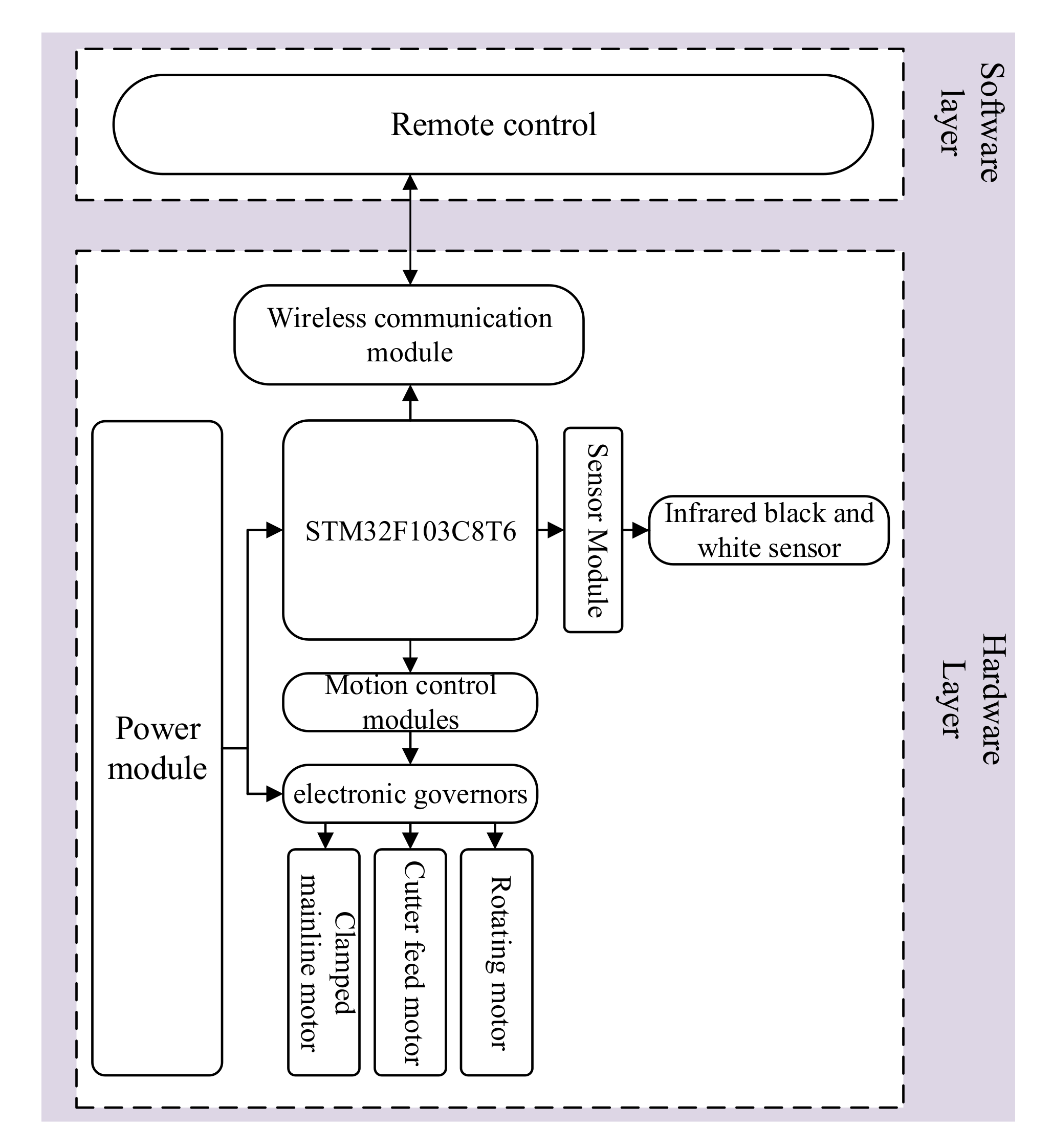
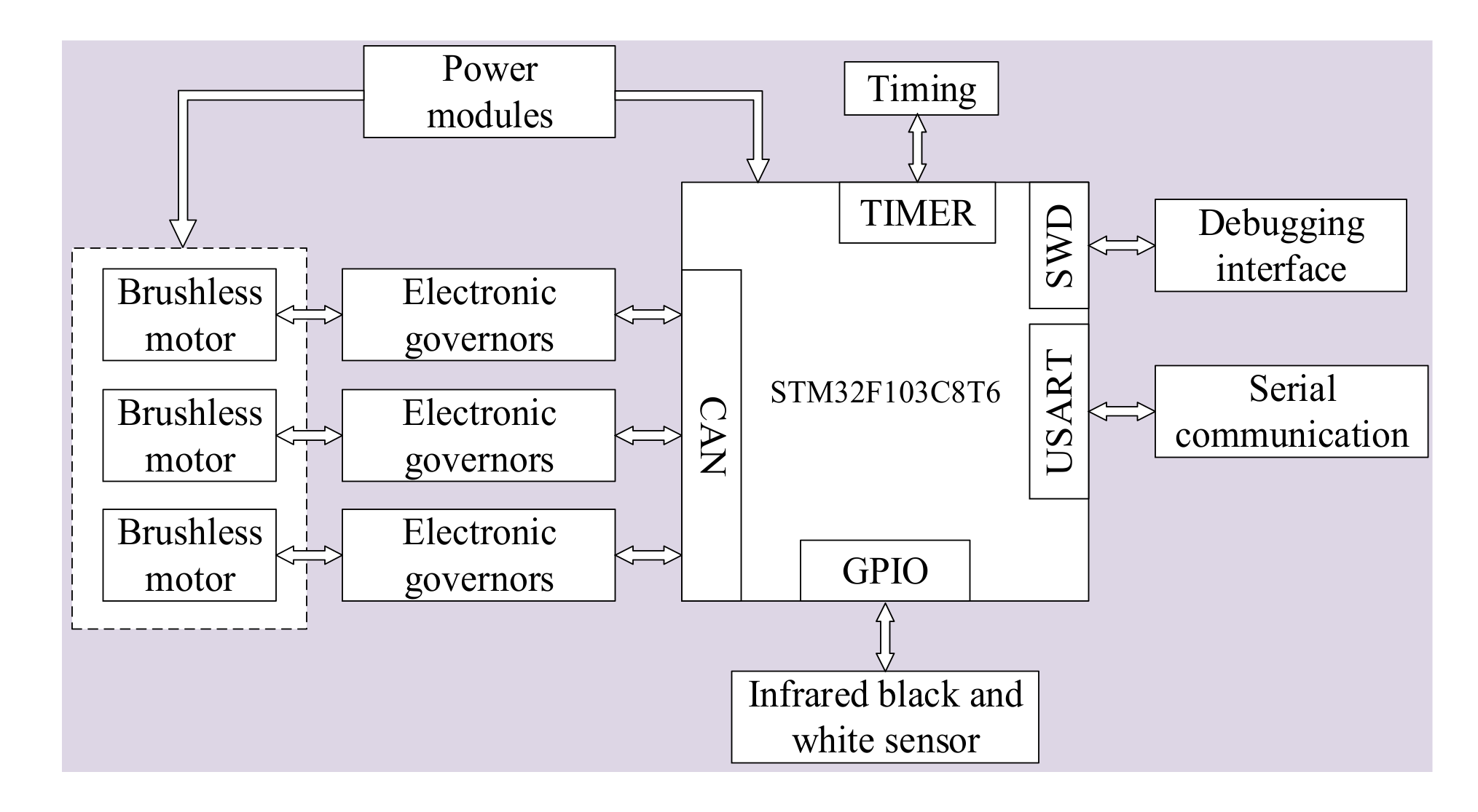
3.1. Hardware Design

Figure 5 depicts the control system’s hardware layout. STM32F103C8T6 is the type of the main chip. This microprocessor is responsible for powering the entire robotic system, controlling motors, and transmitting and receiving signals.

3.1.1. Motors and Electronic Governors

The high-voltage-wire stripping robot’s motion control system is primarily made up of three DC brushless motors and three electronic governors. The robot’s technical specifications in Section II state that the cable clamping motor requires a minimum torque of 0.0048 Nm, the tool feeding motor a minimum torque of 0.0013 Nm, and the rotating stripping motor a minimum torque of 0.94 Nm. It was decided to use a DC brushless geared motor of type M3508 from DJI Corp. with electronic governors of type C620, a rated torque (i.e., maximum continuous torque) of 3 Nm, and a rated speed of 469 rpm.

3.1.2. Infrared Black and White Sensor

Controlling the height of the cutter rise—or the separation between the cutter and the insulated main line—is important for the cutter feed mechanism. The insulating skin stagnation may not be cut if the distance is too great, and if the gap is too small, the wire core may be scratched. The sensor made by HJduino Corp. is used in accordance with the cutter feeding mechanism’s movement characteristics. It has the feature or function that the light source uses a high-brightness condensing LED [18,19], and the receiving tube compares the intensity of various reflected light in order to distinguish between the white wire core and the black insulating skin. When the white wire core is identified, the sensor’s output is low, and the cutter stops moving. When the black insulating skin is detected, the sensor’s output is high and the cutter rises.
The purpose of this sensor is to differentiate between the insulation skin and the wire core. Silver makes up the wire core. The sensor will identify the cable core after the sensor detects the cable core when the blade has completely split open the insulating skin. The motor commands the blade to stop moving at this point since the sensor’s output signal is low. When the blade does not cut into the cable core, this is because the blade is in contact with the insulation skin, which is black rubber material. The object detected by the sensor is the insulation skin. At this time, the sensor output signal is high, and the motor controls the blade to continue cutting until the sensor detects the cable core. The blade only then stops cutting.

3.1.3. Wireless Communication Module

It is decided to use the wireless communication chip CC2530F256, which operates between 2400 and 2450 MHz, and transmits data at a rate of 3300 bps [20,21]. A pair of ZigBee modules are utilized to achieve serial data receipt and transmission; one module is linked to the remote control and the other to the robot.

3.2. Control Algorithm of the Cable-Stripping Robot

In this study, the position loop of the cutter feeding mechanism is controlled by the cascade PID algorithm, and the speed loop of the rotary stripping mechanism is controlled by the fuzzy PID strategy. The fuzzy method is chosen in order to make it easier for wire strippers to adapt to the cutting force of various cable diameters and to obtain better results when removing insulation skin.

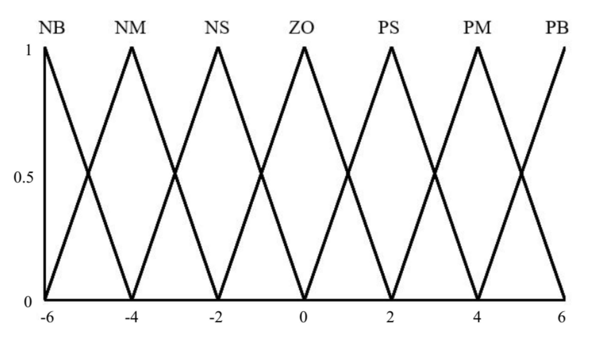
3.2.1. Fuzzy PID Strategy

By continuously gathering error e and error change rate ec and immediately adjusting Kp, Ki, and Kd based on fuzzy rules, fuzzy controllers enable PID parameters to adapt to the system [21]. The expression of the PID controller rectified by fuzzy logic is as follows [22]:
K p = K p + Δ K p K i = K i + Δ K i K d = K d + Δ K d
where K p , K i , and K d are actual PID parameters, K p , K i , and K d are initial PID parameters, and K p , K i , and K d are outputs of the fuzzy regulator.
In this study, the change rate ec of the error e and the error e error are used as inputs to the fuzzy regulator. The error e represents the difference between the rotator stripping motor’s planned speed and the measured actual speed. Seven linguistic variables, NB, NM, NS, ZO, PS, PM, and PB are chosen as fuzzy subsets [23], and the fuzzy domain is set to [−6, 6]. The quantization levels are then separated into seven levels [−6, −4, −2, 0, 2, 4, 6].
The output variables K p , K i , and K d , as well as the theoretical domains of the input quantities e and ec, are chosen to match to the fuzzy rules’ affiliation functions. This study selects a triangle membership function with reduced processing, taking into account that the software runs on the chip STM32F103C8T6. Figure 6 depicts the triangle membership function. Triangular membership functions are used with input quantities e and ec as well as output quantities.
Fuzzy control rules for input quantities e, ec, and output quantities K p , K i , and K d are shown in Table 1.
There are 49 possible fuzzy rules that may be created by combining the above fuzzy speculation table with formulas based on the input amount deviation e and deviation change rate ec. The center of gravity method is used to solve the fuzzy rules [24,25,26].
z 0 = i = 0 n μ c ( z i ) z i i = 0 n μ c ( z i )
where z0 is the exact value after defuzzification, zi the value of the theoretical domain, and μc(zi) the value of the affiliation degree.

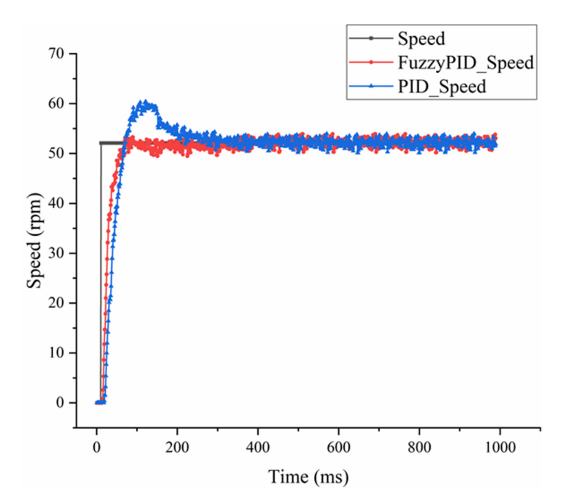
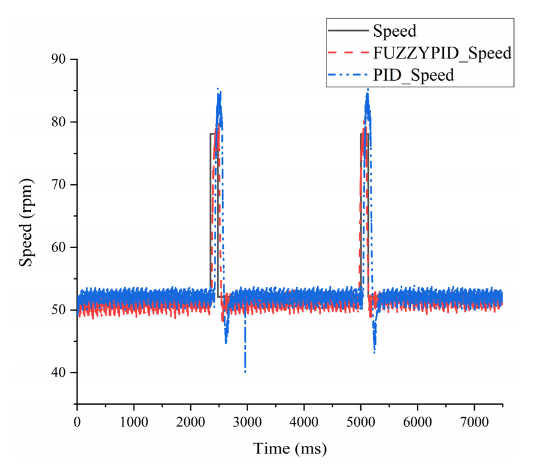
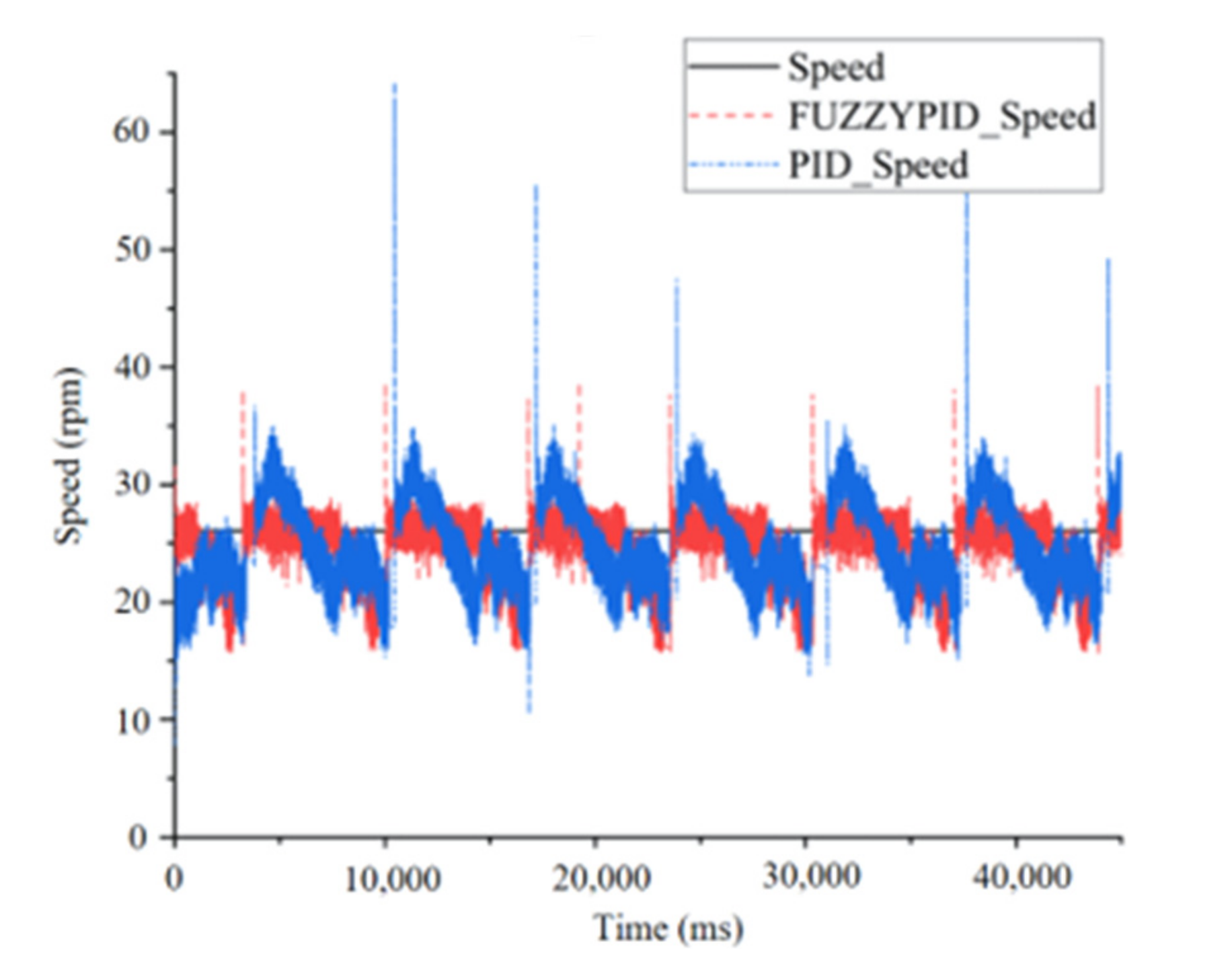
3.2.2. Fuzzy PID Controller and Its Experimental Validations

The insulation skin of the cable will be compressed as a result of the cable’s bending, changing its thickness. The displacement cannot be known since it is hard to determine with accuracy how thick the insulation skin is. As a result, it is inappropriate to operate the cutting module’s motor in position control mode. The motor’s current changes dramatically as a result of the extreme variations in torque it experiences during the cutting operation. In addition, depending on the size of the current, it is impossible to discriminate between the insulation skin and cable core. Consequently, it is incorrect to use current mode. This article uses a speed mode to maintain an appropriate low speed mode for the motor. The motor causes the blade to abruptly stop moving when the sensor detects the cable core; as a result, the motor’s expected speed is set to 0, which can produce effective functioning outcomes.
Considering the rotating mechanism’s cutting force fluctuates throughout the working process, the speed of the rotating motor needs to be accurately calibrated. As a result, a fuzzy PID controller, as seen in Figure 7, is used to tune the motor in the rotating mechanism.
The initial values of the PID controller are set to be K p = 6 , K i = 0.01 , and K d = 0.1 . The theoretical domains of deviation e and deviation rate of change ec are [−270, 270] and [−90, 90], respectively. The theoretical domains of K p , K i , and K d are set to [−1.5, 1.5], [−0.01, 0.01], and [−0.1, 0.1], respectively. The quantization factors are 60, 9000, and 900.
Figure 8 displays the step response curves of the classic PID and fuzzy PID with a motor speed of 52 rpm under no-load conditions. The fuzzy algorithm achieves the target speed in just 20 ms, but the traditional PID controller requires 40 ms. It is obvious that the fuzzy PID control response is faster than the classic PID control response. Comparing the fuzzy PID controller to the traditional PID algorithm, overshooting is significantly minimized.
The results of the fuzzy PID controller can better adapt to the transilience of inputs due to the online tuning of the PID parameters, resulting in the system having smaller errors and faster responses, as shown in Figure 9. Responses of the classic PID have larger overshoots at sudden changes.

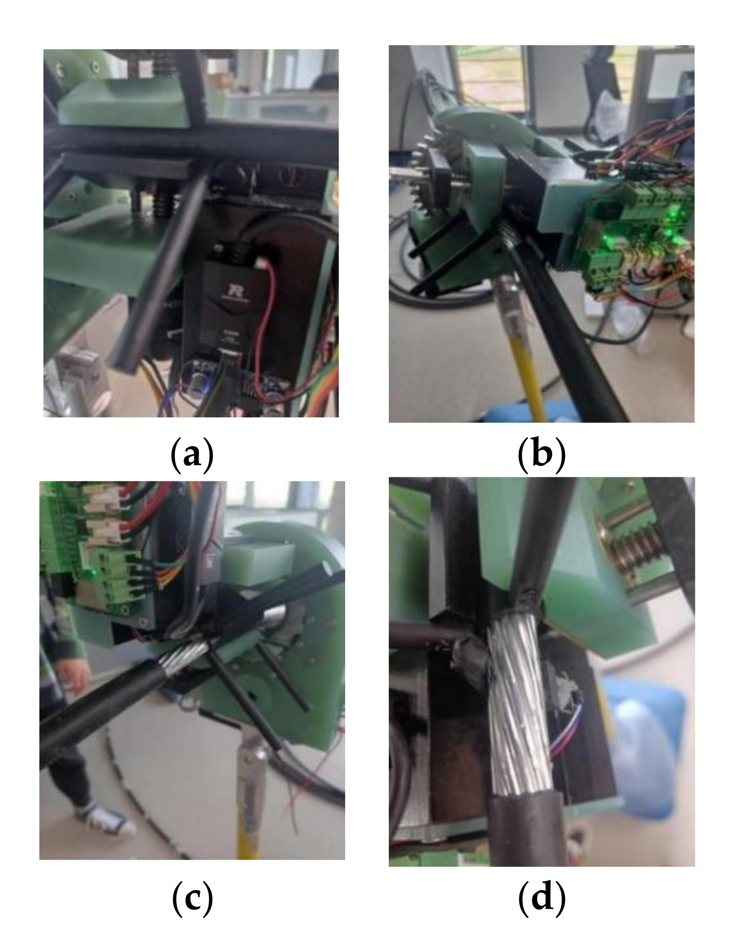
4. Prototype and Validations

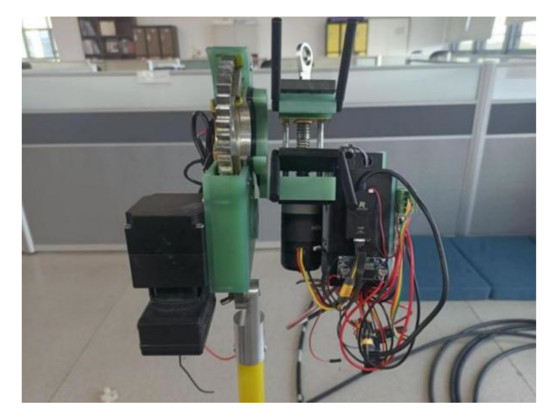
4.1. Prototype of the Robot and Its Workflow

Figure 10 depicts the high-voltage-cable stripping robot prototype. Through the Zigbee wireless communication protocol, the remote control talks to the cable-stripping robot. The entire robot is powered by a DC-24V hand drill battery. The wire remover robot’s approximate 3 kg total mass satisfies the design index of no more than 5 kg suggested in Section 2.
The robot’s workflow diagram is depicted in Figure 11 and explained as follows.
(1) The system is first set up and ready for commands to be sent from the remote control. The robot grips the cable surface through its top and lower V-shape blocks as soon as the start command is delivered.
(2) The cutter will then be lifted to the cable’s insulating surface.
(3) Thirdly, while the cutter keeps rising slowly, the rotating mechanism propels the cutter feeding mechanism and the cable gripping mechanism to rotate in order to remove the insulation skin. The cutter doesn’t stop rising until the infrared black and white sensor notices the white wire core.
(4) The revolving stripping mechanism stops rotating, the cutter returns to its starting position, and the cable gripping mechanism is released once the cable insulation skin has been stripped to the required length.

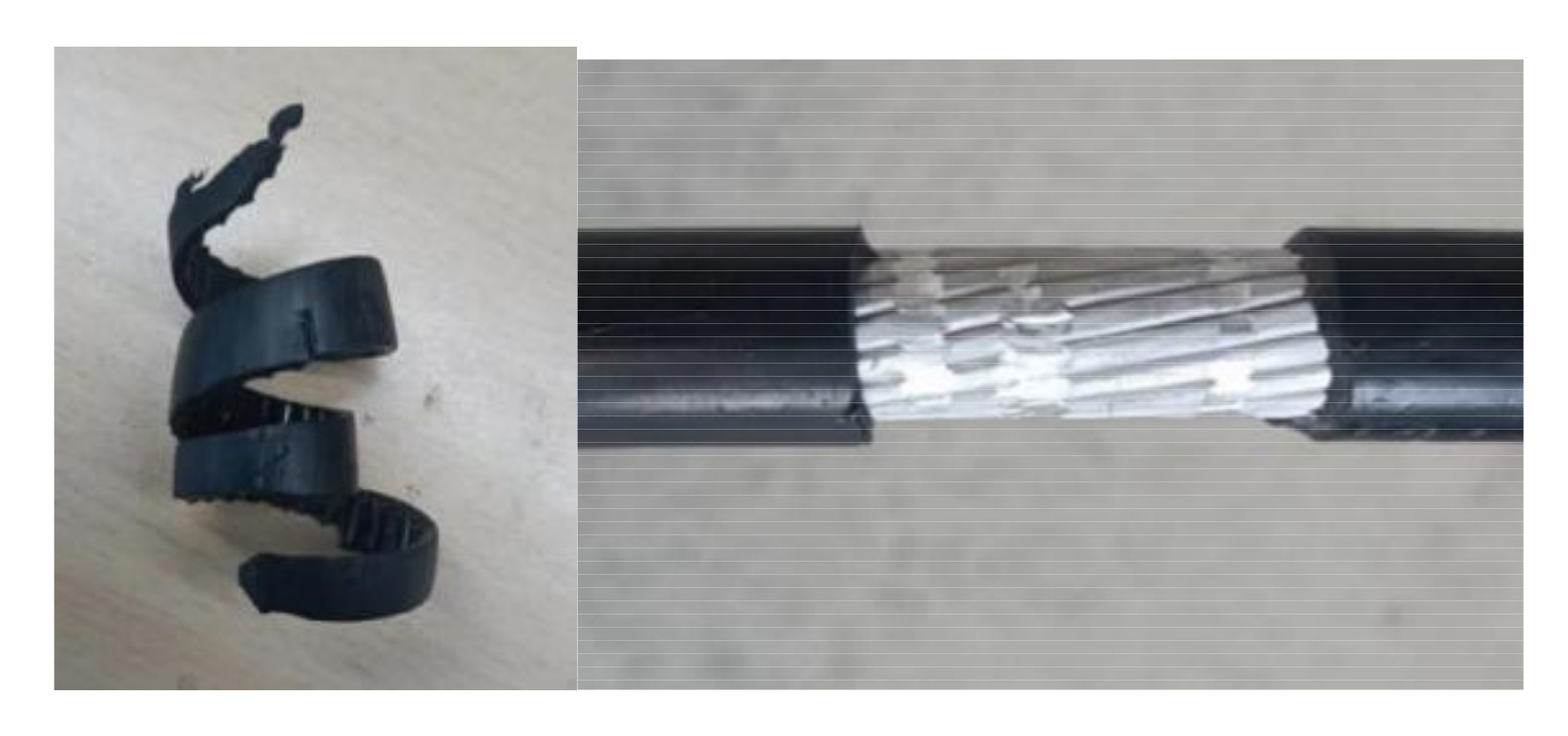
4.2. Experiments and Discussions

The experiment makes use of a cable with a 120 mm2 cross section area (this type of cable is frequently used in 10 kV distribution networks). Figure 12 depicts the cable’s cross-section. Table 2 displays the cable’s essential characteristics.
The rotary stripping motor’s speed command is set to 26 rpm. The wire is travelling at a pace of 7 cm/min, which satisfies the design index of 5 cm/min put forth in section II. For the robot, the impacts of stripping are compared using the traditional PID cascade controller and the fuzzy PID cascade controller, respectively. Figure 13 depicts the fuzzy PID cascade controller’s experimental process.
Both the traditional PID and the fuzzy PID speed response curves are displayed in Figure 14. The speed fluctuation range is between 17.25 rpm and 31.05 rpm, and the fluctuation rate is roughly 60%, as can be seen from the traditional PID speed response curve graph. The time course for the entire ascent was around 5 s, and the actual speed was 17.25 rpm. Because of the gravity of the cutter feed mechanism, when it reaches the maximum of the downward rotational movement, the rotating motor speed overshoots significantly.
The speed fluctuation range of the fuzzy PID strategy’s response curves is between 17.25 rpm and 25.30 rpm, with a 35% fluctuation rate. During the first 2.5 s of the entire ascent, the speed is unable to attain the desired value of 25.30 rpm, but in the second 2.5 s, thanks to the fuzzy PID’s real-time online adjustment of the three PID parameters, the speed is once again close to the desired value. The real speed of the rotating motor is around 24.15 rpm when the cutter feed mechanism reaches the peak of the downward rotational motion, nearly completely unaffected by the acceleration effect of the cutter feeding mechanism due to its own gravity. The rotating motor performs more smoothly during actual use.
Figure 15 displays the results of the stripping process using the traditional PID. The cutting force between the cutter and the insulation layer is not consistent because of the speed’s wide variations. Additionally, the insulation layer chip width varies and is inconsistent, which causes the cutter feeding mechanism to vibrate more and causes significant damage to the cable core.
Figure 16 displays the stripping outcome using a fuzzy PID cascade controller. The speed variation is less as compared to a traditional PID control, and the cable core is obviously not damaged as much.

5. Conclusions

A brand-new high-voltage-cable stripping robot for a 10 kV distribution network is suggested in this research. A rotating mechanism, a cable clamping element, and a cutter feeding element make up the mechanical framework. The control system is thoughtfully designed. A fuzzy PID cascade controller was created with the intention of minimizing damage to the aluminum core. To remove the insulation skin from 120 mm2 overhead insulated cables, a comparative experiment is conducted between the conventional PID controller and the suggested fuzzy PID controller. Results reveal that the fuzzy PID controller has improved resilience and capacity, and the robot can successfully accomplish cable-stripping tasks, demonstrating its potential use in maintaining distribution grids.

Author Contributions

Conceptualization, J.Z.; software, W.A. and Z.W.; experiments, S.H. and H.Z. All authors have read and agreed to the published version of the manuscript.

Funding

This research was funded by National Natural Science Foundation of China 52275285, and Science and technology planning projects of Changzhou CE20215052, China.

Institutional Review Board Statement

Not applicable.

Informed Consent Statement

Not applicable.

Data Availability Statement

The data that support the findings of this study are available from the corresponding author upon reasonable request.

Acknowledgments

This work was supported by National Natural Science Foundation of China (52275285); Science and technology planning projects of Changzhou (CE20215052), China.

Conflicts of Interest

The authors declare no conflict of interest.

Nomenclature

FThe screw thrust
TThe screw torque
PThe screw lead
ηTransmission efficiency
MrCircumferential component torque
μThe friction coefficient

References

  1. Gao, X.; Sun, L.; Zhang, W. Design and Development of High Voltage Live Drainage Robot System. Mach. Des. Res. 2021, 37, 10–14. [Google Scholar] [CrossRef]
  2. Du, Y.; Liu, Y.; Shao, Q.; Sheng, G.; Jiang, X.; Luo, L. Single Line-to-Ground Faulted Line Detection of Distribution Systems with Resonant Grounding Based on Feature Fusion Framework. In Proceedings of the 2020 IEEE Power & Energy Society General Meeting (PESGM), Montreal, QC, Canada, 2–6 August 2020; p. 1. [Google Scholar] [CrossRef]
  3. Sun, J.; Yang, Q.; Xu, W.; He, W. A Distribution Line Fault Location Estimation Algorithm Based on Electromagnetic Time-Reversal Method Calculated in the Finite Difference Time Domain. IEEE Trans. Electromagn. Compat. 2022, 64, 865–873. [Google Scholar] [CrossRef]
  4. Takaoka, K.; Yokoyama, K.; Wakisako, H.; Yano, K.; Higashijima, K.; Murakami, S. Development of the fully-automatic live-line maintenance robot-Phase III. In Proceedings of the 2001 IEEE International Symposium on Assembly and Task Planning (ISATP2001). Assembly and Disassembly in the Twenty-first Century. (Cat. No.01TH8560), Fukuoka, Japan, 29 May 2001; pp. 423–428. [Google Scholar] [CrossRef]
  5. Yano, K.; Maruyama, Y.; Morita, K.; Nakashima, M. Development of the semi-automatic hot-line work robot system “Phase II”. In Proceedings of the ESMO’95—1995 IEEE 7th International Conference on Transmission and Distribution Construction, Op-eration and Live-Line Maintenance, Columbus, OH, USA, 29 October–3 November 1995; pp. 212–218. [Google Scholar] [CrossRef]
  6. Nakashima, M.; Yano, K.; Maruyama, Y.; Yakabe, H. The hot line work robot system “Phase II” and its human-robot in-terface “MOS”. Proceedings 1995 IEEE/RSJ International Conference on Intelligent Robots and Systems. Human Robot Interaction and Cooperative Robots, Pittsburgh, PA, USA, 5–9 August 1995; Volume 2, pp. 116–123. [Google Scholar] [CrossRef]
  7. Pouliot, N.; Montambault, S. LineScout Technology: From inspection to robotic maintenance on live transmission power lines. In Proceedings of the 2009 IEEE International Conference on Robotics and Automation, St. Louis, MO, USA, 25–28 March 1985; pp. 1034–1040. [Google Scholar]
  8. Penin, L.F.; Aracil, R.; Ferre, M.; Pinto, E.; Hernando, M.; Barrientos, A. Telerobotic system for live power lines maintenance: ROBTET. In Proceedings of the 1998 IEEE International Conference on Robotics and Automation (Cat. No.98CH36146), Leuven, Belgium, 20–20 May 1998; Volume 3, pp. 2110–2115. [Google Scholar]
  9. Zhao, Y.; Qi, H.; Xu, W.; Li, J.; Zhao, J. Research on Master-slave Controlling Remote Operation of Live Working Robots in Agricultural Distribution Network. In Proceedings of the 2018 IEEE 3rd Advanced Information Technology, Electronic and Automation Control Conference (IAEAC), Chongqing, China, 12–14 October 2018; pp. 1401–1405. [Google Scholar] [CrossRef]
  10. Han, W. An Automatic Stripping Device for Hot-line Connection of 10 kV Cables. J. Phys. Conf. Ser. 2021, 2005, 012211. [Google Scholar] [CrossRef]
  11. Lei, T.; Xie, Z.; Wang, K.; Zhong, L.; Chen, D. Design of high voltage live operation robot system. In Proceedings of the 2021 International Conference on Wireless Communications and Smart Grid (ICWCSG), Hangzhou, China, 13–15 August 2021; pp. 473–476. [Google Scholar]
  12. Zhang, J.; Hu, Y.; Xu, S.; Zhang, T.; Ren, S.; Wang, M. Design and analysis of terminal live installation tool for robot in distribution work. Procedia Comput. Sci. 2021, 183, 412–417. [Google Scholar] [CrossRef]
  13. Yan, Y.; Liu, L.; Zhou, Z.; Fan, Y. Development of Live Working Robot for Distribution Network. IOP Conf. Ser. Earth Environ. Sci. 2019, 237, 062026. [Google Scholar] [CrossRef]
  14. Seki, H.; Nakayama, S.; Uenishi, K.; Tsuji, T.; Hikizu, M.; Makino, Y.; Kakiuchi, A.; Kanda, Y. Development of assistive robotic arm for power line maintenance. Precis. Eng. 2020, 67, 69–76. [Google Scholar] [CrossRef]
  15. Feng, J.; Zhang, W. Autonomous Live-Line Maintenance Robot for a 10 kV Overhead Line. IEEE Access 2021, 9, 61819–61831. [Google Scholar] [CrossRef]
  16. Liming, Z.; Yulong, H.; Shanjun, X.; Tong, Z.; Junlong, G.; Mingrui, W. Mechanical design and finite element analysis of live working robot for 10kV distribution power systems. Procedia Comput. Sci. 2021, 183, 331–336. [Google Scholar] [CrossRef]
  17. Zhang, M.; Du, J. Design and development of smart socket based on STM32. J. Comput. Methods Sci. Eng. 2020, 20, 227–243. [Google Scholar] [CrossRef]
  18. Hu, Y.; Chen, C.; Wu, H.; Song, C. Study on structural optimization design and cascade PID control of maglev actuator for active vibration isolation system. J. Vib. Control 2016, 24, 1829–1847. [Google Scholar] [CrossRef]
  19. Li, J.; Zhang, L.; Huang, X.; Zhang, Q.; Wang, G. Cascade PID control algorithm for wind turbine blade mold temperature based on improved RBF neural network. Acta Energ. Sol. Sin. 2022, 43, 330–335. [Google Scholar] [CrossRef]
  20. Lyu, D.; Su, H.; Li, Y.; Zhang, Z.; Long, H.; Zhao, J. An Embedded Linear Model Three-Dimensional Fuzzy PID Control System for a Bionic AUV under Wave Disturbance. Math. Probl. Eng. 2022, 2022, 4126595. [Google Scholar] [CrossRef]
  21. Tang, X.; Wang, C.; Hu, Y.; Liu, Z.; Li, F. Adaptive Fuzzy PID Based on Granular Function for Proton Exchange Membrane Fuel Cell Oxygen Excess Ratio Control. Energies 2021, 14, 1140. [Google Scholar] [CrossRef]
  22. Zhang, L.; Zhang, L.; Yang, J.; Gao, M.; Li, Y. Application Research of Fuzzy PID Control Optimized by Genetic Algorithm in Medium and Low Speed Maglev Train Charger. IEEE Access 2021, 9, 152131–152139. [Google Scholar] [CrossRef]
  23. Jiang, W.; Liu, G.; Wang, T.; Gao, K. Variable universe fuzzy PID control based on adaptive contracting-expanding factors. Eng. Mech. 2021, 38, 23–32. [Google Scholar]
  24. Zhou, J.; Li, Z.; Li, X.; Wang, X.; Song, R. Human–Robot Cooperation Control Based on Trajectory Deformation Algorithm for a Lower Limb Rehabilitation Robot. IEEE/ASME Trans. Mechatron. 2021, 26, 3128–3138. [Google Scholar] [CrossRef]
  25. Fan, R.; Li, Y. An Adaptive Fuzzy Trajectory Tracking Control via Improved Cerebellar Model Articulation Controller for Electro-Hydraulic Shovel. IEEE/ASME Trans. Mechatron. 2021, 26, 2870–2880. [Google Scholar] [CrossRef]
  26. Wang, T.; Wang, H.; Hu, H.; Lu, X.; Zhao, S. An adaptive fuzzy PID controller for speed control of brushless direct current motor. SN Appl. Sci. 2022, 4, 71. [Google Scholar] [CrossRef]
Figure 1. Power distribution lines.
Actuators 12 00201 g001
Figure 2. General scheme of the cable-stripping robot.
Actuators 12 00201 g002
Figure 3. A 3D model of the high-voltage-cable stripping robot.
Actuators 12 00201 g003
Figure 4. The overall structure of the controlling system.
Actuators 12 00201 g004
Figure 5. Hardware scheme of the controller.
Actuators 12 00201 g005
Figure 6. The triangular membership function.
Actuators 12 00201 g006
Figure 7. Speed loop fuzzy PID.
Actuators 12 00201 g007
Figure 8. Speed response curves of the rotating mechanism activated by the classic PID and fuzzy PID controller, respectively.
Actuators 12 00201 g008
Figure 9. Responses of classic PID and fuzzy PID under activation of rectangular wave signals.
Actuators 12 00201 g009
Figure 10. Prototype of the cable-stripping Robot.
Actuators 12 00201 g010
Figure 11. The work flowchart of the robot.
Actuators 12 00201 g011
Figure 12. The cable and its cross-section.
Actuators 12 00201 g012
Figure 13. Cable-stripping process of the robot employing fuzzy algorithm. (a) Start working; (b) Feed motion; (c) Forward motion; (d) Stripping complete.
Actuators 12 00201 g013
Figure 14. Speed response curves of classic PID and fuzzy PID.
Actuators 12 00201 g014
Figure 15. Stripping effect of the robot using classic PID cascade controller.
Actuators 12 00201 g015
Figure 16. Stripping effect of the robot using fuzzy PID cascade controller.
Actuators 12 00201 g016
Table 1. Fuzzy rule speculations.
K . ec
NBNMNSZOPSPMPB
eNBPB/NB/PSPB/NB/NSPM/NM/NBPM/NM/NBPS/NS/NBZO/ZO/NMZO/ZO/PS
NMPB/NB/PSPBNB/NSPM/NM/NBPS/NS/NMPS/NS/NMZO/ZO/NSNS/ZO/ZO
N
S
PM/NB/ZOPM/NM/NSPM/NS/NMPS/NS/NMZO/ZO/NSNS/PS/NSNS/PS/ZO
ZOPM/NM/ZOPM/NM/NSPS/NS/NSZO/ZO/NSNS/PS/NSNM/PM/NSNM/PM/ZO
P
S
PS/NM/ZOPS/NS/ZOZO/ZO/ZONS/PS/ZONS/PS/ZONM/PM/ZONM/PB/ZO
PMPS/ZO/PBZO/ZO/NSNS/PS/NSNM/PS/PSNM/PM/PSNM/PB/PSNB/PB/PB
P
B
ZO/ZO/PBZO/ZO/PMNM/PS/PMNM/PM/PMNM/PM/PSNB/PB/PSNB/PB/PB
Table 2. Main parameters of the high-voltage-cable with 120 mm2 section area.
TypeNominal Cross-Sectional Area (mm2)Number of Aluminum WiresAluminum Wire Diameter (mm)Insulation Layer Thickness (mm)
JKLYJ120240.82.5
Disclaimer/Publisher’s Note: The statements, opinions and data contained in all publications are solely those of the individual author(s) and contributor(s) and not of MDPI and/or the editor(s). MDPI and/or the editor(s) disclaim responsibility for any injury to people or property resulting from any ideas, methods, instructions or products referred to in the content.

