Article

Dual Synthetic Jets Actuator and Its Applications Part V: Novel Valveless Continuous Micropump Based on Dual Synthetic Jets with a Tesla Structure

College of Aerospace Science and Engineering, National University of Defense Technology, Changsha 410073, China
*
Author to whom correspondence should be addressed.
Actuators 2023, 12(6), 226; https://doi.org/10.3390/act12060226
Submission received: 5 May 2023 / Revised: 25 May 2023 / Accepted: 27 May 2023 / Published: 29 May 2023

Abstract

:
The valveless micropump based on dual synthetic jets is a potential fluid pumping device that has the ability to transport fluid continuously. In order to improve the performance of this device, a novel valveless continuous micropump based on dual synthetic jets with a Tesla structure was proposed by combining a double Tesla symmetrical nozzle and a dual synthetic jets actuator. The mechanism of the novel micropump and its flow field characteristics were analyzed, combined with numerical simulation and a PIV experiment. The performance of the novel micropump was compared with that of a dual synthetic jet micropump based on a traditional shrinking nozzle. The novel micropump achieved continuous flow with a larger and more stable flow rate in one cycle. The maximum pump flow speed reached 12 m/s. Compared with the traditional type, the pump flow rate was increased by 5.27% and the pump flow pulsation was reduced by 214.93%. The backflow and vortex inside the nozzle were prevented and inhibited effectively by the Tesla structure. The velocity and influence range of the pump flow increased with the intensification of driving voltage in a certain range.

1. Introduction

The microfluidic system holds immense potential for a wide range of applications, including drug delivery [1,2,3], biochemical applications [4,5,6,7,8], robotics [9,10], micro-electronics cooling [11,12,13], and more. As the core of this system, micropump plays a crucial role in its overall functionality. It can be used for energy conversion, directional and quantitative fluid transfer, and even as a power source for micro-robots. Without the micropump, the whole system would not work properly. Micropumps can be classified into two categories: mechanical and non-mechanical [14]. Non-mechanical micropumps can generate constant/steady flows (compared with oscillatory pumping). Their performance, however, is often limited by the properties of the selected fluid. Mechanical micropumps often use the motion of a solid (such as a gear or diaphragm) or liquid to generate the pressure difference needed to move fluid. The motion often causes an unsteady flow. The piezoelectric pump is a type of non-mechanical micropump that utilizes the inverse piezoelectric effect of piezoelectric materials. The application of alternating current excitation can deform the piezoelectric material, thereby driving the fluid. The piezoelectric pump has the advantages of a compact structure, low energy consumption, a flexible control mode, and fast response times. Valveless piezoelectric pumps are particularly noteworthy as they enable the directional transport of fluid by optimizing the pump structure. This design avoids the hysteresis of the mechanical valve under high-frequency conditions and the problem of fatigue damage.
Conventional valveless pumps, such as contract/expansion tube valveless pumps, are not widely applicable in microfluidic systems due to their shortcomings, such as their inability to continuously discharge and large outflow pulsation. In 1998, Glezer, A. et al. [15] developed the first piezoelectric synthetic jet actuator (SJA) with superior working characteristics, which has been extensively studied by researchers and introduced into the field of micropump research [16]. Luo, X.B. et al. [17] first applied synthetic jets to a micropump in 2002. The feasibility of a synthetic jet micropump was verified through numerical simulation, providing a novel approach for valveless micropump design. Building on this foundation, Luo, Z.B. et al. [18] designed a valveless micropump based on synthetic jets with a filter by employing two piezoelectric diaphragms in 2005 that avoided the blockage caused by impurities from the outside and significantly increased the flow rate of the pump. Dau, V.T. et al. [19], Choi, J.P. et al. [20], He, X.H. et al. [21], Munas, F.R. et al. [22], and Van, L.L. et al. [23] developed different structures for valveless piezoelectric micropumps based on synthetic jets, such as the planar [19,20,22,23] and vertical [21] structures, and carried out a large number of numerical simulations and experimental studies on them. Through excellent structure design, these researchers enabled the micropump to have the ability of directional fluid transport and improved the directivity of fluid flow. Some of them achieved a continuous pumping flow of the micropumps [21,22,23]. However, these micropumps had some drawbacks, such as a less compact structure, insufficient development space for synthetic jets, low pump flow, and large pulsations. Tran, C.D. et al. [24] proposed a micropump based on synthetic jets with a Tesla coupled nozzle in 2020 on the basis of these predecessors. Through the novel Tesla coupled nozzle, the energy contained in the vortices on either side of the synthetic jet was utilized during the blowout phase. During the suction stage of the pump, the main stream stagnated, causing the cavity to only absorb air from the side roads. However, this design still has some drawbacks, such as unstable pump flow and an inability to withstand high ballasts.
In summary, although the valveless micropump based on synthetic jets can generate a continuous jet flow through the structure design, there are some issues such as unsteady pump flow, ballast invalidation, and low energy utilization rate. The fundamental reasons for this are that the synthetic jet actuators cannot pump fluid continuously and the environment on both sides of the diaphragm is inconsistent. In 2006, the piezoelectric dual synthetic jets actuator (DSJA) was invented by Luo, Z.B. et al. [25,26], which solved the above problems by sharing one PZT diaphragm with two cavities. Building on this innovation, Luo’s team developed a continuous micropump based on dual synthetic jets [27] and conducted numerical simulations and performance analyses on it. The simulation results showed that the micropump had the characteristics of continuous flow and low pulsation.
In order to further improve the performance of the continuous micropump based on dual synthetic jets, this paper designed a novel valveless continuous micropump based on dual synthetic jets with a Tesla structure. This micropump combined the novel double Tesla symmetrical nozzle with a dual synthetic jets actuator. The mechanism and flow field characteristics of the novel micropump were analyzed through numerical simulation and particle image velocimetry (PIV) experiments, which laid a theoretical foundation for the engineering application of a valveless continuous micropump based on dual synthetic jets.

2. Structure and Numerical Methods

2.1. Structure and Mechanism

The structure and specific parameters of the novel micropump designed in this paper are shown in Figure 1. The micropump was composed of a nozzle and actuator cavity. The actuator cavities featured two shrinking outlets. The interior of the nozzle contained a flow guide baffle, two suction channels, and a Tesla symmetrical structure. The idea of this structure was inspired by the Tesla principle of preventing undesired backflow. The outlet area of the nozzle measured 3 mm × 30 mm.
The working mechanism of the valveless continuous micropump based on dual synthetic jets is illustrated in Figure 2. The piezoelectric diaphragm underwent an inverse piezoelectric effect under the external alternating current excitation, vibrating in the actuator cavity along the normal direction of the diaphragm. In the first half cycle, as shown in Figure 2a, when the piezoelectric diaphragm vibrated to the left, the left cavity was compressed, while the right cavity expanded. The compressed air in the left cavity formed a jet in the left outlet of the actuator cavity. Under the action of the Coanda surface at the bottom of the flow guide baffle, the jet flowed into the main channel along the curved surface. The jet was in the forward flow state and was directly expelled through the nozzle contraction outlet and stabilization section, unaffected by the Tesla backflow channel through which it flowed. At the same time, the right cavity expanded and formed a low-pressure region. Since the Tesla structure only allowed the fluid to pass through in one direction, it could obstruct the reverse flow of the main channel. Therefore, the right cavity could only take in air from the outflow field through the suction channel. In the second half cycle, the diaphragm vibrated to the right; thus, the flow field was contrary to the above description. The left cavity provided the main flow in the first half cycle, while the right cavity did so in the second half cycle, resulting in a continuous flow within one cycle at the nozzle.

2.2. Numerical Model and CFD Method

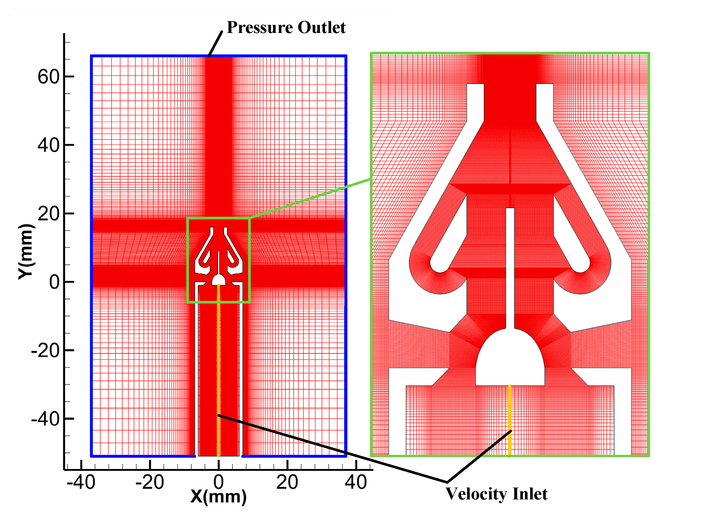
The established two-dimensional numerical model of the valveless continuous micropump based on dual synthetic jets is shown in Figure 3. The numerical model used was the X-L model [28]. The velocity inlet boundary condition was given directly in terms of its time-dependent displacement. The calculation expression was as follows:
u x = 2 π f A m · sin 2 π f t + Φ 0 , u l l , t 0
where u x l , t and u l l , t are, respectively, the axial and radial components of the velocity at any point on the surface of the diaphragm ( x 1 , l ), where A m is the amplitude of the center point of the diaphragm.
In this study, the UDF file was imported to define the velocity inlet. The diaphragm vibration amplitude was specified as A m = 0.01857   m m and the frequency was specified as f = 600 Hz. Then, the formulas were as follows:
u 1 x = 0.7 sin 2 π · 600 · t u 2 x = 0.7 sin 2 π · 600 · t + π
where u 1 x and u 2 x are the normal velocities of the left and right diaphragm, respectively.
The simulation software used in this study was Ansys Fluent 2021R2. The SST k-ω turbulence model was selected for numerical calculation. The vibration diaphragm adopted the velocity inlet boundary while the wall adopted the non-slip wall boundary, and the surrounding outlet was set as the pressure outlet. The fluid medium was an incompressible gas. The pressure-based solver was chosen for calculation as it requires a small amount of memory and has a high degree of resilience in solving, making it suitable for a wide range of flow systems, from low-speed incompressible flows to high-speed compressible flows. The Semi-Implicit Method for Pressure Linked Equations (SIMPLE) was used for the pressure and velocity coupling, and the momentum and energy equations were discretized using the second-order upwind scheme. Structured grids were employed throughout the computational domain, which was locally encrypted inside the nozzle and at the exit. The number of grids was 244,666. A cycle of the actuator was divided into 80 steps for calculation, that is, the time step Δ t = 1 / 80 T = 1 / 80 × 600 s = 2.08333 × 10 5 s .

2.3. Grid Independence Verification

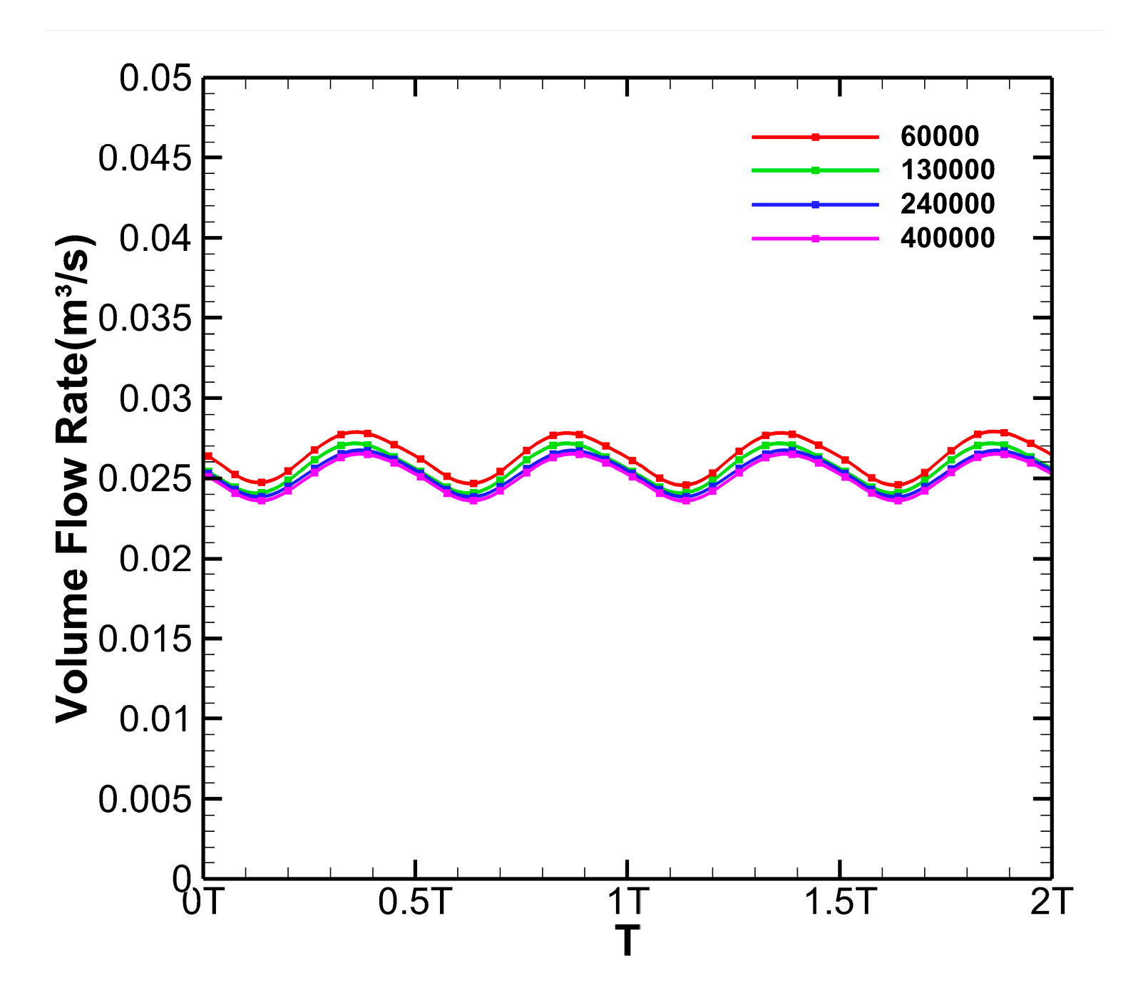
The numerical calculation was carried out on the two-dimensional models, with the number of grids being 60,000, 130,000, 240,000, and 400,000 by learning a considerate method [29]. After calculating for 50 cycles, the instantaneous flow rate curve in the nozzle outlet within two cycles was obtained, as shown in Figure 4. The instantaneous flow rate results calculated by the four grid quantities had few differences. The difference and average flow rate are shown in Table 1. The flow rate decreased slightly with the increase in the number of grids and gradually tended to be stable. Compared with the calculation results where the number of grids was 400,000, the errors in the calculations with the other numbers of grids were, respectively, 4.74%, 2.15%, and 0.92%. In order not to compromise the calculation accuracy and efficiency, this paper adopted a model with a grid number of 240,000 for numerical calculation.

2.4. PIV Experimental Method

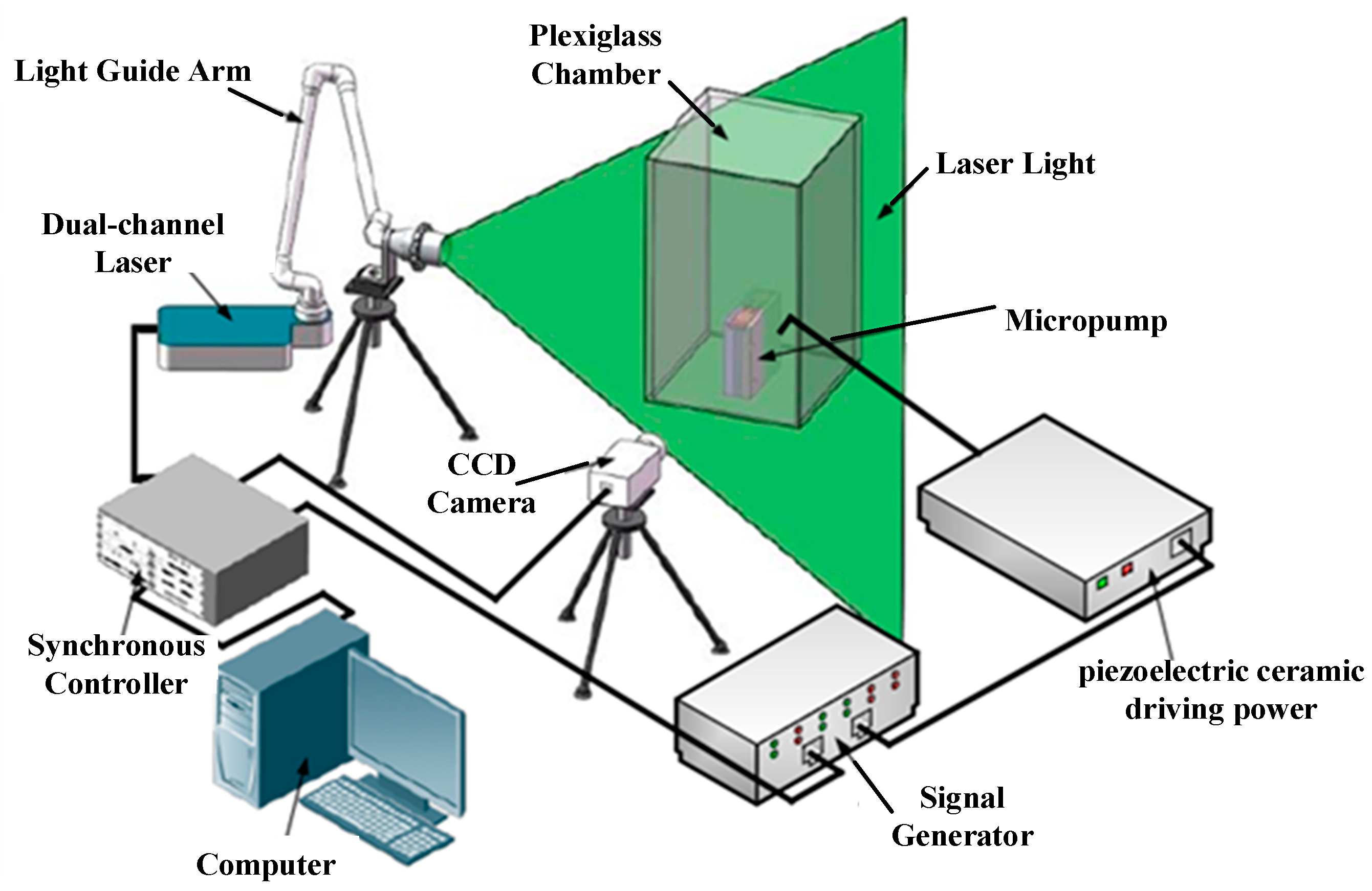
The composition of the PIV experimental system is shown in Figure 5. The PIV system mainly included a high-energy dual-channel laser, three-dimensional light guide arm, 24 mm F/2.8 long lens, 532 ± 5 nm narrow-band filter, cross-frame CCD camera (2456 × 2056), synchronous frequency-locking controller, image acquisition card, and MicroVec V3 system PC software. The micropump was placed in a plexiglass chamber (200 mm × 200 mm × 600 mm), which was filled with smoke particles less than 4µm in diameter as PIV tracer particles. Two signals with the same frequency and phase were generated by the signal generator, one of which was provided to the actuator by the piezoelectric ceramic driving power supply, and the other was used as the external trigger signal of the synchronous controller to realize the phase-locked measurement of the flow field. In the experiment, the image magnification was 21.3136 μm/pixel. The operating frequency of the time-averaged flow field image acquisition was 7 Hz. The images taken at this frequency could be traversed through the whole cycle of the valveless duel synthetic jet micropump. A total of 50 pairs of images were taken, and the mean value of the images was taken as the velocity vector of the time-averaged flow field. A cycle of the valveless dual synthetic jet micropump flow field was divided into 16 phase points by using synchronization and phase-locked technology, and 10 pairs of images were taken for the flow field at each phase point. The mean value was taken as the velocity vector of the phase point. The laser light was located at the middle section of the micropump, and the nozzle exit pointed to the laser light.

3. Results and Analysis

3.1. Instantaneous Flow Field

A cycle could be divided into four stages according to the diaphragm vibration regularity (taking the left cavity as the research object): accelerated blowing stage, 0 < t ≤ 1/4T (the first stage); deceleration blowing stage, 1/4T < t ≤ 1/2T (the second stage); accelerated suction stage, 1/2T < t ≤ 3/4T (the third stage); and deceleration suction stage, 3/4T < t ≤ T (the fourth stage).
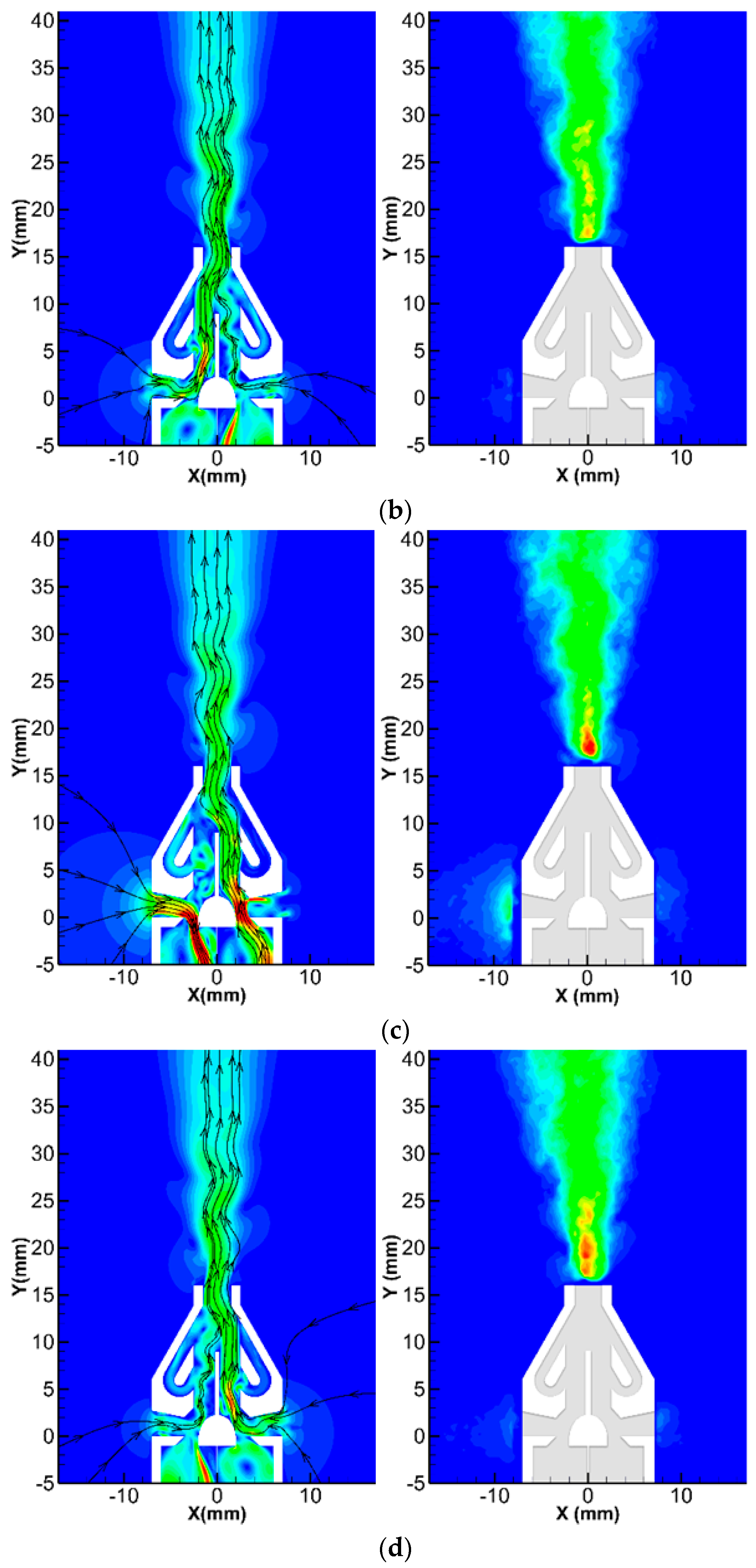
Figure 6 shows the velocity and streamline of the flow field in the simulation and the PIV diagram of the operation of the valveless micropump based on dual synthetic jets in one cycle. When t = 1/4T, as shown in Figure 6a, the left cavity of the micropump was at the end of the accelerated blowing stage. At this stage, the entire micropump was manifested as accelerated blowing in the left cavity and accelerated suction in the right cavity. The air in the left cavity was constantly compressed and ejected from the left cavity outlet. Under the action of the Coanda effect, the jet flowed into the left main channel along the curved surface at the bottom of the flow guide baffle. The jet then continued to develop downstream and was expelled after flowing through the nozzle contraction outlet and stabilization section. During the accelerated blowing stage, the air at the edge of the cavity outlet experienced strong shear action from the jet stream, leading to the formation of a vortex inside the suction channel. The vortex sucked up part of the main stream, resulting in an overflow shunt at the upper end of the channel. The vortex also drove the overflow shunt to move back into the main stream to avoid flow loss. The jet in the contraction outlet deflected towards the center at the end of the flow guide baffle and collided with the wall of the contraction outlet, causing some of the air to separate from the main stream and flow into the Tesla backflow channel. The air in the Tesla backflow channel flowed along the channel and collided with the air in the right main channel, forming a mass of large and small whirlpools that prevented the right cavity from inhaling air in the right main channel. Therefore, the right cavity outlet could only inhale air from the outside through the right suction channel. This entire process also elucidated the working mechanism of the Tesla structure, specifically, how it functioned to impede the reverse flow.
The PIV diagram shows that there was a clear air inhalation phenomenon around the right suction channel, which was asymmetric in comparison to the left side. This suggested that the right cavity was currently inhaling air from the outside through the right suction channel. In the left suction channel, some air was observed escaping from the channel, confirming the presence of a vortex in the left channel. The flow field around the left and right suction channels was consistent with the simulation results.
When t = 1/2T, as shown in Figure 6b, the left cavity of the micropump was at the end of the deceleration blowing stage. At this stage, the left cavity was still being compressed, but the degree of compression was constantly decreasing, as was the intensity of the jet from the left cavity. The jet ejected in the previous stage developed into the left main channel. The high-speed flow generated low pressure in the left main channel, allowing external air with relatively high pressure to enter the left main stream via the left suction channel due to the pressure difference. There was also a pressure difference between the main jet in the contraction outlet and the relatively static air in the right main channel. Additionally, the main jet had an ejection effect on the air in the right main channel, making the air flow into the main jet. Since it was then at the end of the deceleration blowing stage, the right cavity no longer inhaled air. The air inhaled from the outside during the previous period had no time to stagnate and flowed directly into the right main channel under the guidance of the structure, supplementing the air in the right main channel. These figures illustrate the complete jet flow phenomenon from the exterior into the main jet.
As observed in the PIV diagram, the air speed near the right suction channel at this stage was significantly reduced compared with the previous stage. This indicated that the right cavity was at the end of the deceleration suction stage, and the suction speed was greatly reduced. During this time, the inhaled air was added to the right main channel, and the left suction channel was slightly inhaling air. This action, which was contrary to the previous stage, also confirmed the phenomenon described in the simulation: the outside air was replenished in the left main channel due to the pressure difference.
Figure 6c,d, respectively, show the flow conditions of the micropump when t = 3/4 t and t = T. In these periods, the left cavity was at the end of the accelerated suction stage and the deceleration suction stage, respectively, and the flow conditions were exactly opposite to those when t = 1/4T and t = 1/2T. In the first half cycle, the micropump was characterized by left blowing and right suction, while in the second half cycle, it was characterized by left suction and right blowing. Consequently, the micropump exhibited continuous flow at the jet nozzle within a single cycle.

3.2. TimeMean Flow Field

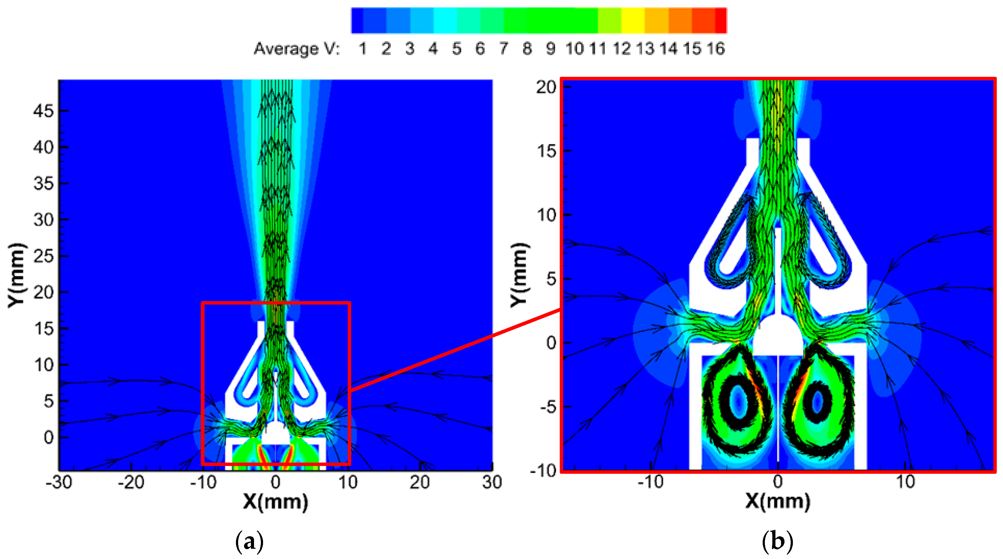
Figure 7 shows the time-mean flow field of the micropump in one cycle. Within a cycle, the micropump continuously inhaled air from the outside. The air flowed successively through the suction channel, the flow guide baffle, and the main channel, and was finally ejected through the nozzle, showing a shape similar to the steady jet outside the nozzle. This process realized the micropump function of directional transport air. In addition, the time-mean flow field had a clear dividing line at the throat outlet of the cavity, which indicated that the cavity did not eject or inhale air in one cycle, and the total mass flow rate of the cavity in one cycle was still zero, although there was a mass exchange between the cavity and the outside surroundings.
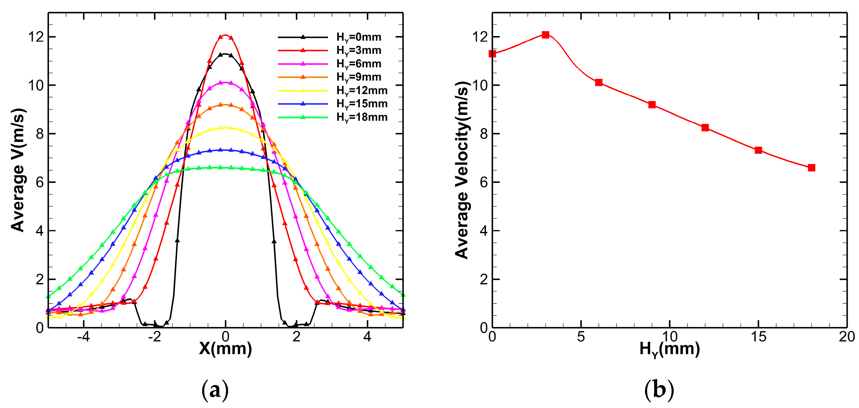
The velocity distribution and maximum velocity magnitude at different altitudes (0 H Y 18 is equal to 16 mm Y 34 mm) are given in Figure 8a, showing the law of velocity distribution in a downstream flow. At position H Y = 0 , the velocity presented unimodal symmetry, with lower magnitude on both sides of the center and a large velocity gradient in the X direction. At position H Y = 3 , the central maximum velocity magnitude and the velocity on both sides of the center increased. For the velocity gradient in the X direction, the gradient decreased on both sides of the center but increased in the middle. As H Y continued to grow, the peak magnitude of the unimodal symmetric velocity distribution gradually decreased; this was accompanied by a larger range on both sides of the center and a flatter distribution. Due to the wall boundary layer on both sides of the nozzle stabilization section at H Y = 0 , the velocity magnitude here was close to 0. The jet was compressed and ejected at the nozzle contraction section. The closer the jet was to the center, the higher the energy was. The energetic central jet formed strong shear with the stationary air in the boundary layer, thus showing a unimodal symmetric velocity distribution. When H Y increased, the wall limit disappeared, and the jet gradually expanded to both sides. The expansion became clearer with the increase in altitude. After expansion, the energy concentrated in the middle of the jet was dispersed to both sides, resulting in the development of velocity distribution from unimodal symmetry to flat. The velocity (maximum velocity) of the flow field center at different altitudes was obtained, as shown in Figure 8b. As the distance increased, the maximum velocity magnitude first increased and then decreased, reaching a maximum at approximately 12 m/s at position H Y = 3 , and was approximately linear at the velocity decay stage.
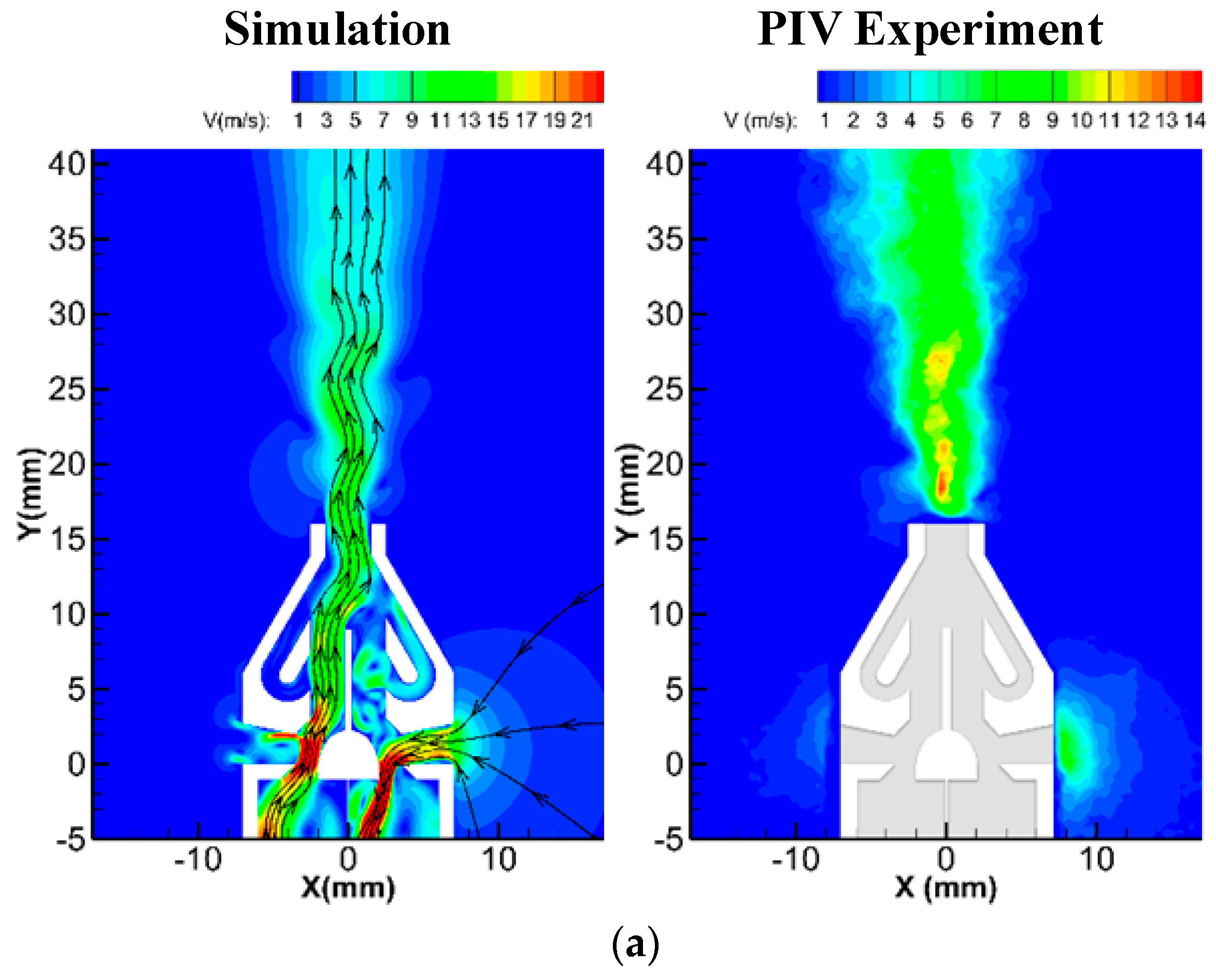
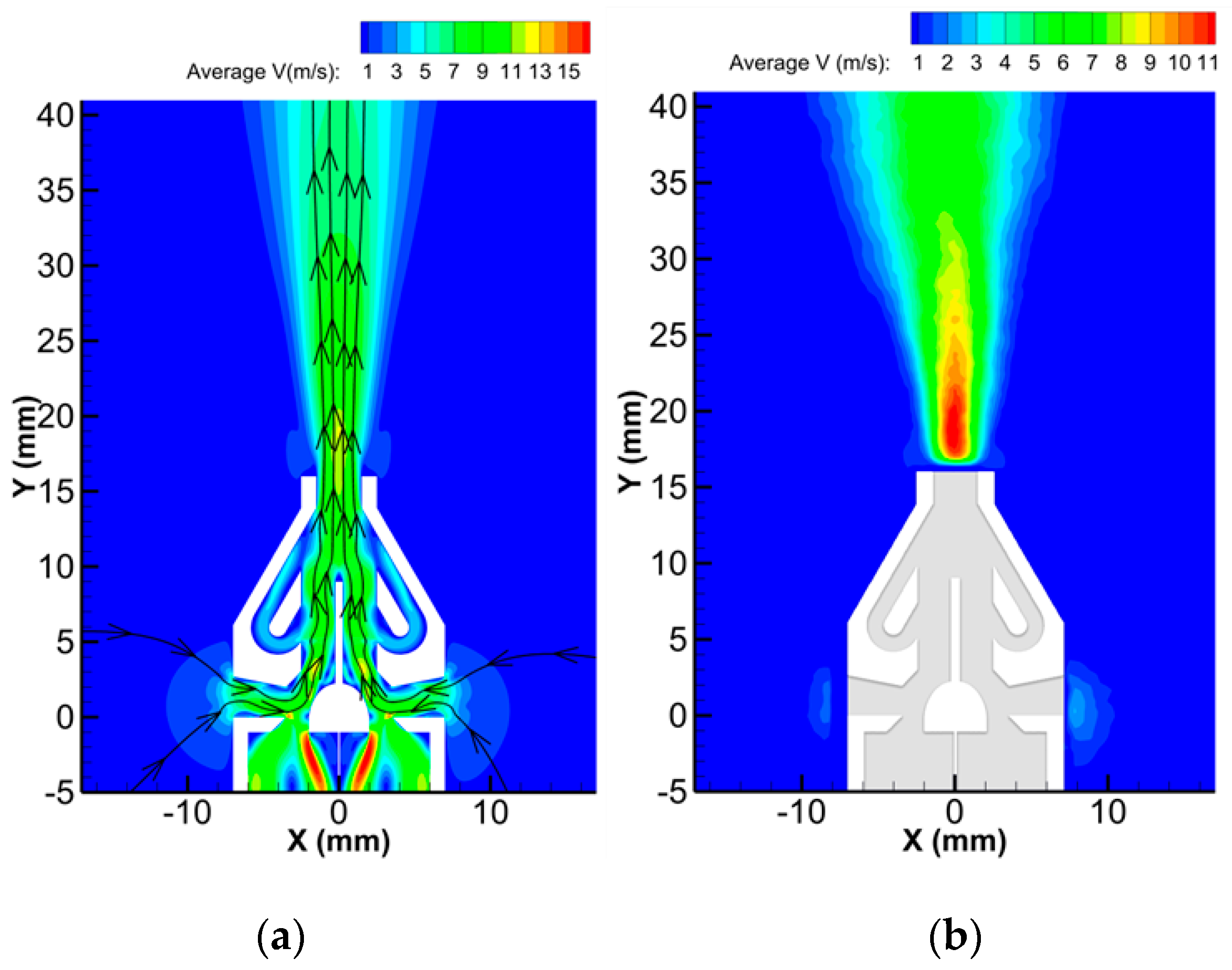
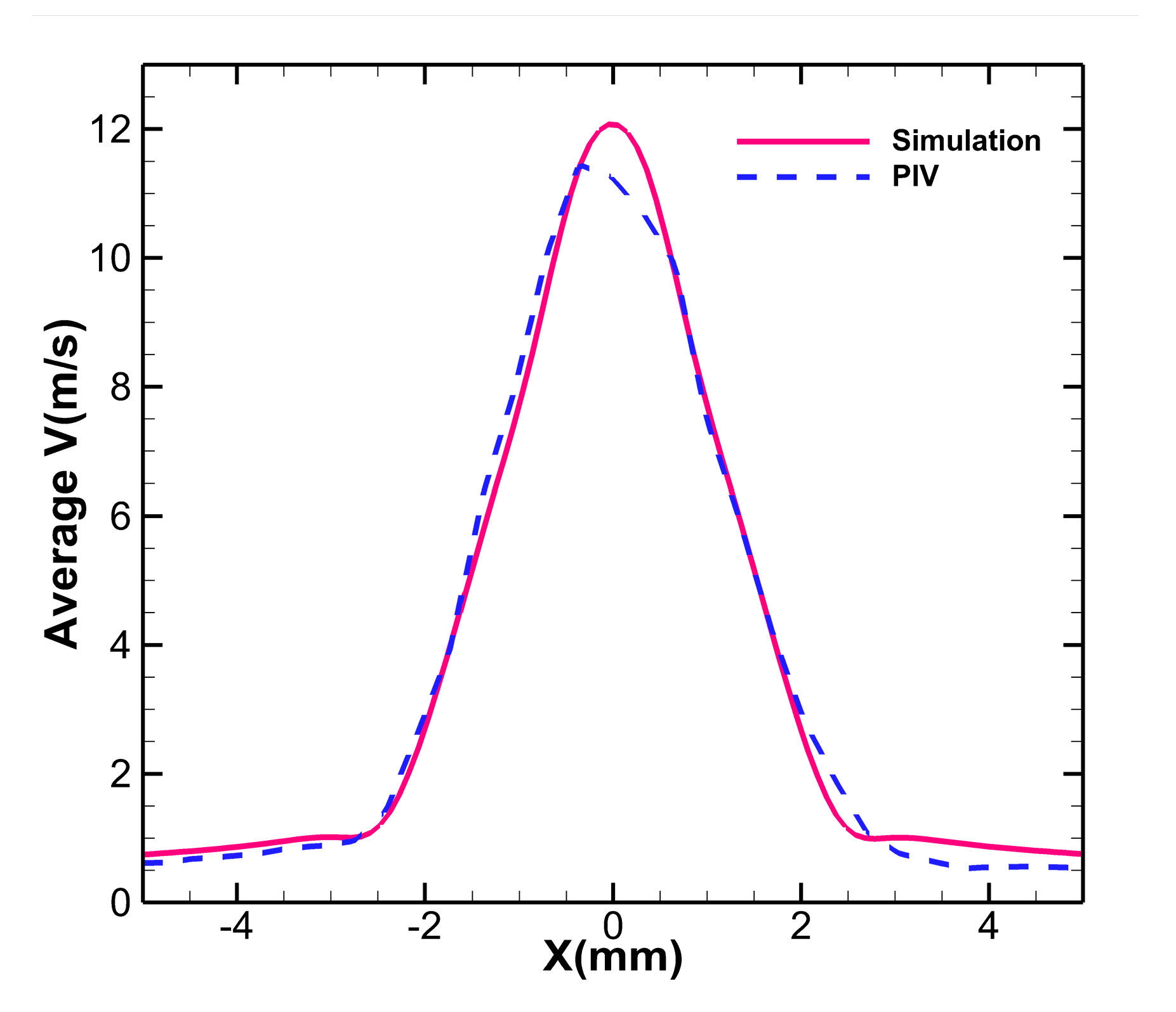
The PIV experimental system was used to photograph the real flow field downstream of the micropump. Time equalization processing was carried out and the simulation flow field was compared, as shown in Figure 9. At this time, the diaphragm driving voltage was 150 V and the driving frequency was 660 Hz. The real flow field diagram shows that the jet flowed out continuously from the nozzle, and there was no backflow at the nozzle exit. The downstream velocity field was similar to that of the steady jet flow and was in agreement with the simulation results. Outside the suction channel, the suction velocity shown in the PIV diagram was not clear. This was because as the momentum during the suction process was smaller than that during the injection process, the disturbance caused by the suction process was weaker. Additionally, after the air had flowed into the suction channel, the camera of the PIV device was unable to capture the particles, resulting in inaccurate shots of the flow field in this region. Figure 10 compares the velocity distribution of the real flow field with the simulation result at H Y = 3 . The velocity distribution of the real flow field also presented a form of unimodal symmetry, which was in high agreement with the simulation result.

3.3. PIV Results Analysis

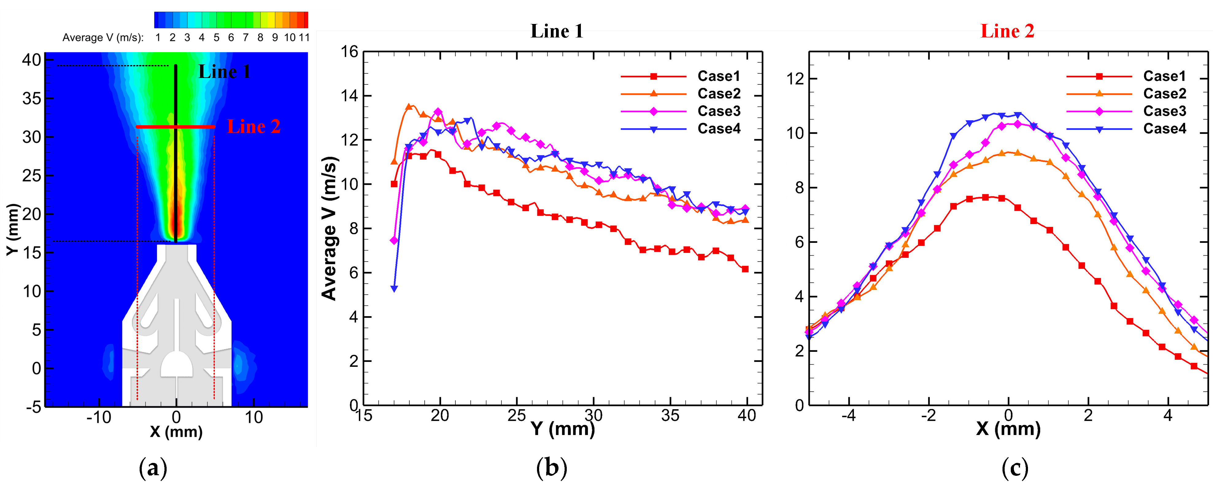
By changing the driving voltage amplitude, the micropump performance and downstream flow field changes were investigated. The PIV system was used to photograph the time-mean flow field of the micropump under different driving voltage amplitudes, as shown in Figure 11. As shown in the figure, the shape of the downstream jet did not change as the driving voltage amplitude increased, but the influence range of the jet expanded. Here, the angle between the two rays was used to measure the influence range of the jet. Table 2 shows the relationship between voltage amplitude and the angle.
At Y = 40 mm, which was 24 mm downstream of the nozzle, the influence range of the jet increased from 38.5° (in voltage 150 V) to 43.1° (in voltage 210 V), representing an increase of 11.95%. When the driving voltage amplitude was 240 V, the influence range was slightly reduced to 42.2°. Although the range of influence decreased somewhat, it may have been caused by the shooting error. Thus, with the further increase in driving voltage amplitude, the range of influence gradually tended to stabilize.
The velocity magnitude of the flow field center (X = 0 mm) in the range of Y = 17~40 mm was extracted and compared, as shown in Figure 12b. When the voltage was 150 V, the velocity reached its maximum at approximately Y = 20 mm and decayed with the increase in distance. When the voltage was increased to 180 V, the velocity generated by the diaphragm increased, and the velocity of the downstream flow field also increased significantly. The maximum velocity magnitude grew from 11 m/s to approximately 13.5 m/s. The local velocity of the corresponding position also integrally increased by approximately 1–2 m/s, and the penetrability of the jet was enhanced. As the driving voltage continued to rise, the maximum velocity of the jet decreased slightly by approximately 0.5 m/s, but the velocity at the same position still increased. Moreover, the position of the maximum velocity moved downstream constantly. The maximum velocity was near Y = 18 mm at 180 V, Y = 20 mm at 210 V, and Y = 22 mm at 240 V. It is known from previous studies that the influence range of jets increases with voltage amplitude. Since the jet developed downstream in an “S” form, the larger influence range meant that the jet was “getting fatter”. Although the velocity generated by the diaphragm increased after the voltage rose, the “fatter” jet led to a dispersion of energy in the jet center. Thus, the maximum velocity of the jet was reduced, which also indicated that the penetrability of the micropump had reached the threshold.
Figure 12c shows the velocity distribution at Y = 32 mm under different driving voltage amplitudes. With the growth in voltage, the velocity magnitude presented an overall upward trend, which was reflected in the increase of the maximum velocity and both sides. The area enclosed by the velocity distribution curve and the coordinate axis became larger, which meant that the larger the flow rate, the more gas could be transported and the stronger the transport capacity. Therefore, although increasing the voltage could not effectively improve the penetrability of the micropump jet, it could enhance the transport capability of the micropump.

3.4. Comparison with the Traditional Shrink Nozzle

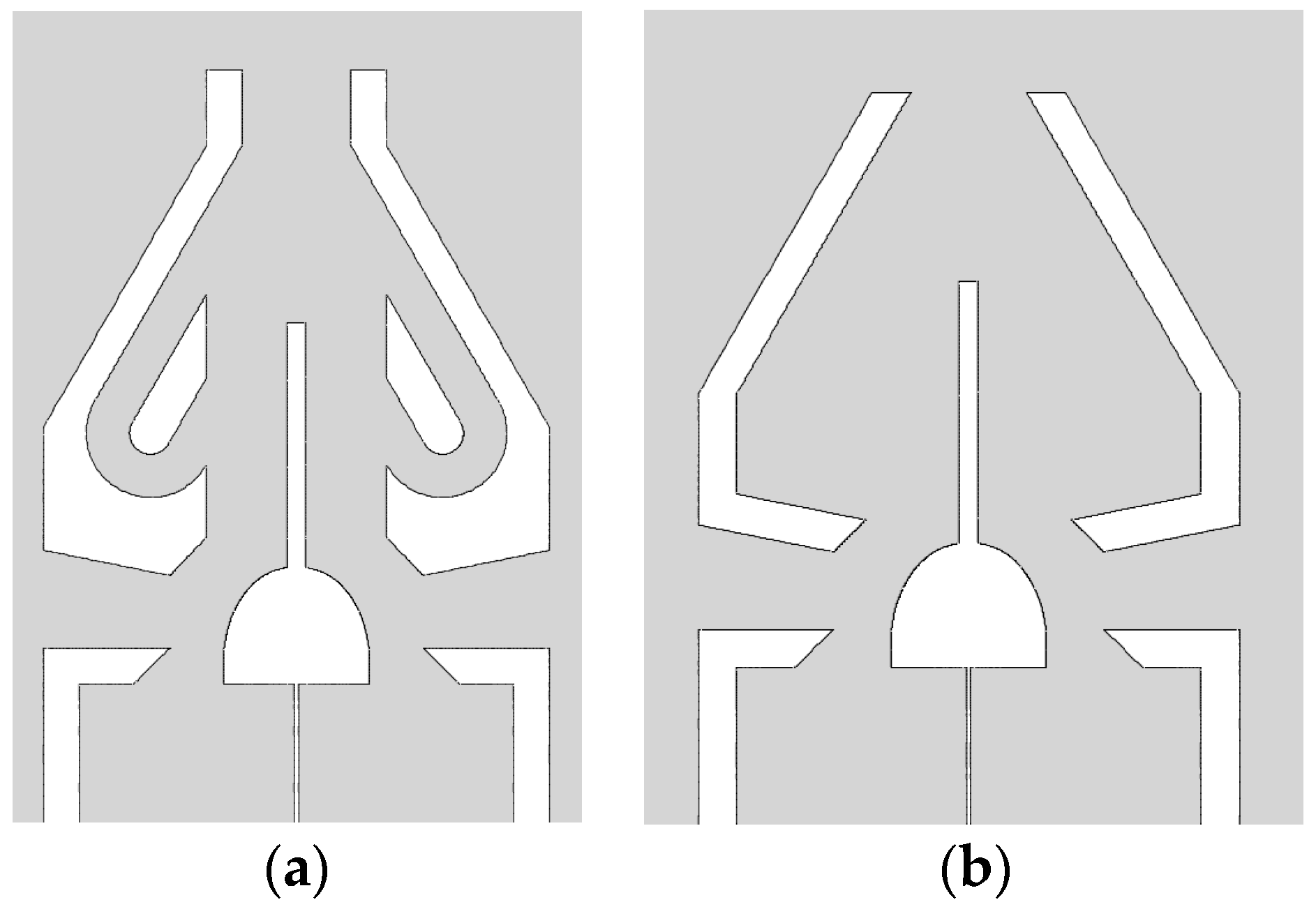
In order to reflect the advantages of the novel Tesla symmetrical nozzle over the traditional shrink nozzle, a simulation investigation of the shrink nozzle was carried out. The structure is shown in Figure 13, which adopted the same CFD method. The number of grids was 173,428.
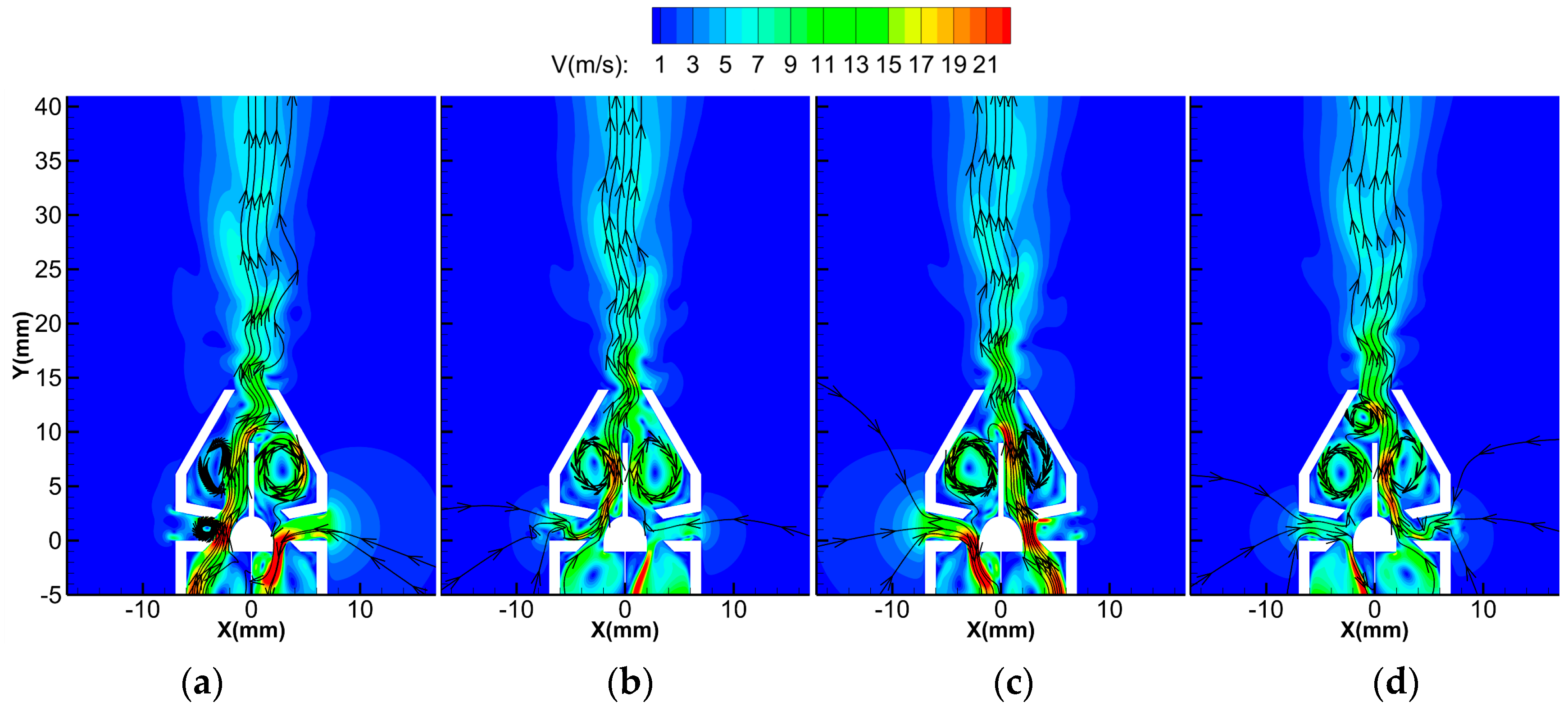
Figure 14 shows the flow field inside the shrink nozzle in one cycle. In the first stage, large vortices were formed on both sides inside the nozzle. Part of the main jet flowed into the right vortex under attraction, taking away the energy. At the same time, attracted by the vortex, the main jet deflected to the right at the end of the flow guide baffle and impinged on the wall of the contraction outlet, further consuming the energy of the main jet. The figure also shows that at the bottom of the right vortex, some air flowed out of the vortex and was sucked into the right cavity along with the gas in the suction channel. This phenomenon is called “self-absorption”. This phenomenon hinders the jet from developing downstream, affecting the speed of the jet, and can even cause the jet to continuously circulate in the nozzle. Therefore, the occurrence of the “self-absorption” phenomenon should be avoided as far as possible. In the second stage, the two vortices were still in existence. At this time, there was no energy being continuously added to the main jet. The main jet, which had not yet developed downstream, could not resist the attraction of the right vortex and was sucked into it, increasing the energy of the right vortex.
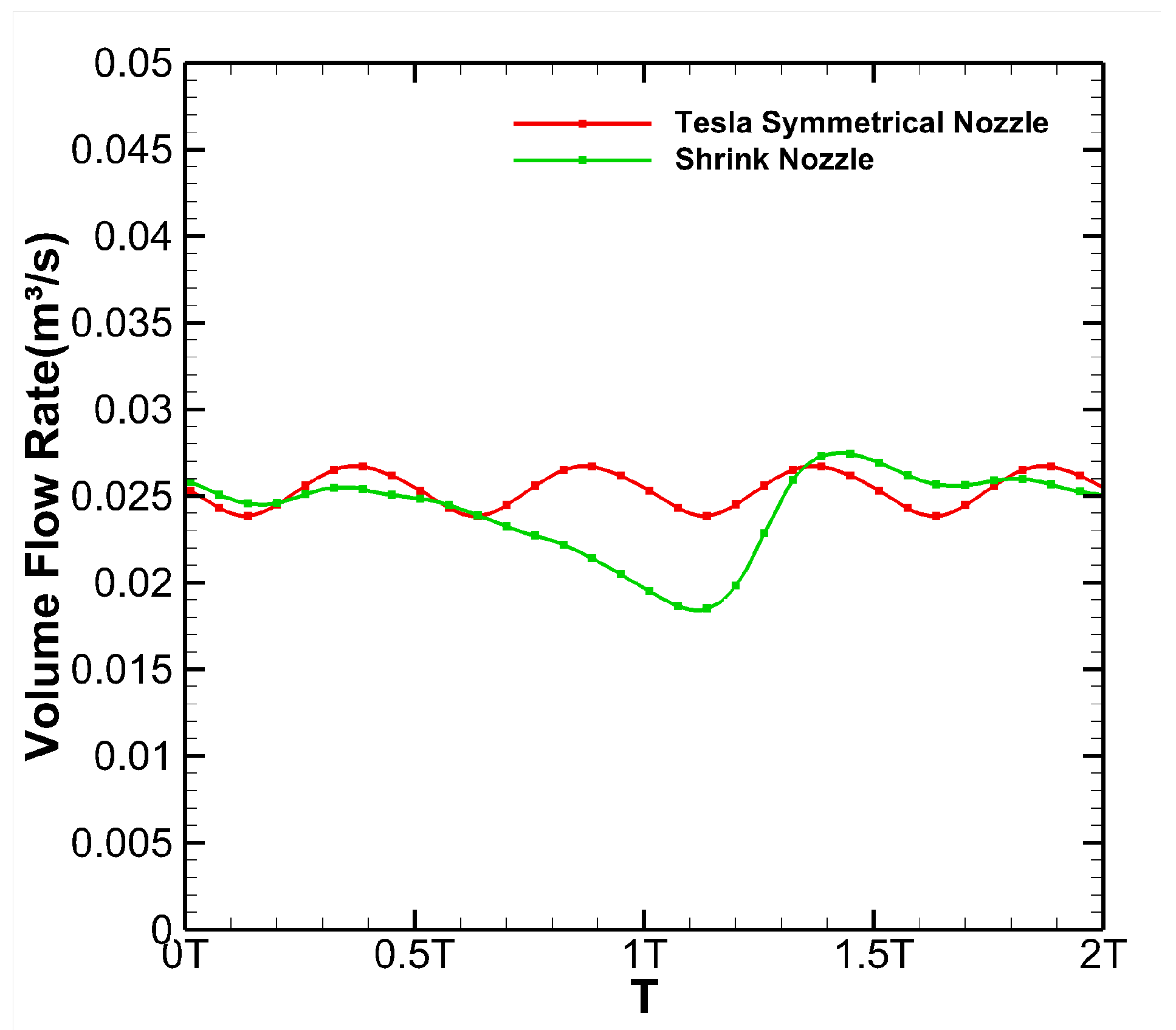
Throughout the whole cycle, vortices always existed on both sides due to the nozzle that had no Tesla structure. This carried several disadvantages. Firstly, the energy of the main jet was weakened by the vortices, which reduced the strength and flow rate of the downstream jet. Secondly, the attraction effect of the vortex made the main jet deflection angle excessive at the end of the flow guide baffle, resulting in the poor directivity of the jet in the downstream direction. Finally, the vortex inside the nozzle made the flow field more complicated, resulting in large and irregular flow rate fluctuations at the nozzle outlet. Figure 15 shows the instantaneous volume flow rate curves of the two structures. The instantaneous volume flow rate of the shrinking nozzle was slightly greater than that of the nozzle with the Tesla structure in some moments, but most times, it was not. From the perspective of average volume flow rate, the average volume flow rate of the shrink nozzle within two cycles was 0.02409 m3/s and that of the Tesla symmetrical nozzle was 0.02536 m3/s, an increase of 5.27%. From the perspective of flow rate stability, the flow rate of the shrink nozzle was not periodic, and the difference between the maximum and minimum instantaneous flow rate was as high as 0.00907 m3/s. Although the flow rate of the Tesla symmetrical nozzle also fluctuated, the maximum difference in instantaneous flow rate was only 0.00288 m3/s. Compared with the contraction nozzle, the fluctuation degree was greatly reduced by 214.93%. In addition, the flow rate of the Tesla symmetrical nozzle was also periodic, which means that the value of the flow rate at any time could be obtained according to the periodic law.
This shows that the Tesla symmetrical nozzle was superior to the contraction nozzle in all aspects. First of all, the Tesla structure inside the nozzle could play a directional diversion role on the shunt generated by the main jet impinging on the wall surface of the contraction outlet. This allowed the shunt to be re-injected into the main jet through the Tesla backflow channel, and this energy could be reused to avoid waste. Secondly, the Tesla structure could eliminate the vortex, which improved the flow rate and made the flow fluctuation small and periodic. Finally, the Tesla structure could also effectively stagnate the backflow, and its unique unidirectional conduction function prevented the jet in the nozzle from being sucked into the cavity again; thus, the “self-absorption” phenomenon did not occur.

4. Conclusions

In this paper, a novel valveless continuous micropump based on dual synthetic jets with a Tesla structure was designed. Numerical simulations and PIV tests were carried out. The following conclusions were obtained:
(1)
The novel valveless continuous micropump based on dual synthetic jets with a Tesla structure could realize the directional transport of fluid. Through the reciprocating vibration of the diaphragm, the micropump could periodically inhale fluid from both sides and alternately eject the jet from the nozzle. It was able to continuously eject the fluid within one cycle and the pumping flow rate was relatively stable.
(2)
The numerical simulation results showed that the downstream time-mean flow field of the micropump presented a unimodal symmetry pattern. The maximum velocity on the center line of the flow field increased first and then decreased as the distance from the nozzle outlet grew. It appeared at a distance of 3 mm from the nozzle outlet and reached 12 m/s. Even at a distance of 24 mm, the velocity reached 6 m/s.
(3)
The PIV results showed that the influence range of the micropump jet could be effectively enlarged by increasing the driving voltage amplitude within a certain range (±150 V~±210 V), and the maximum influence range was 43.1°. With the increase in driving voltage amplitude, the maximum velocity of the micropump jet first increased and then remained at a stable value. At 180 V driving voltage, the maximum velocity reached 13.5 m/s. Although the increase in the voltage could not effectively improve the maximum velocity of the jet, it could enhance the transport capability of the micropump.
(4)
Compared with the traditional shrinking nozzle, the double Tesla symmetrical nozzle could eliminate the internal vortex and enhance the flow rate by 5.27%, making the flow rate more stable and periodic.

Author Contributions

Writing—original draft preparation, J.-Y.Z.; writing—review and editing, W.-Q.P., Z.-B.L., Z.-J.Z., J.-Y.G., Z.-F.D. All authors have read and agreed to the published version of the manuscript.

Funding

This research was funded by the National Natural Science Foundation of China, grant numbers 52075538 and U2141252, and the Provincial Natural Science Foundation of Hunan, grant number 2023JJ30622.

Institutional Review Board Statement

Not applicable.

Informed Consent Statement

Not applicable.

Data Availability Statement

Not applicable.

Conflicts of Interest

The authors declare no conflict of interest.

References

  1. Cobo, A.; Sheybani, R.; Tu, H.; Meng, E. A wireless implantable micropump for chronic drug infusion against cancer. Sens. Actuator A Phys. 2016, 239, 18–25. [Google Scholar] [CrossRef]
  2. Bußmann, A.; Leistner, H.; Zhou, D.; Wackerle, M.; Congar, Y.; Richter, M.; Hubbuch, J. Piezoelectric Silicon Micropump for Drug Delivery Applications. Appl. Sci. 2021, 11, 8008. [Google Scholar] [CrossRef]
  3. Rubayet, H.; Sevki, C.; Mahmoud, B.; Anthony, P.; Austin, R. A Magnetorheological Duckbill Valve Micropump for Drug Delivery Applications. Micromachines 2022, 13, 723. [Google Scholar]
  4. Atsushi, T.; Kenichi, K.; Hiroaki, S. Autonomous microfluidic control by chemically actuated micropumps and its application to chemical analyses. Anal. Chem. 2010, 82, 6870–6876. [Google Scholar]
  5. Do, V.K.; Yamamoto, T.; Ukita, Y.; Takamura, Y. Precise flow control with internal pneumatic micropump for highly sensitive solid-phase extraction liquid electrode plasma. Sens. Actuators B Chem. 2015, 221, 1561–1569. [Google Scholar] [CrossRef]
  6. Kant, R.; Singh, D.; Bhattacharya, S. Digitally controlled portable micropump for transport of live micro-organisms. Sens. Actuators A Phys. 2017, 265, 138–151. [Google Scholar] [CrossRef]
  7. Vedran, B.; Denis, D. All Silica Micro-Fluidic Flow Injection Sensor System for Colorimetric Chemical Sensing. Sensors 2021, 21, 4082. [Google Scholar]
  8. Bußmann, A.; Thalhofer, T.; Hoffmann, S.; Daum, L.; Surendran, N.; Hayden, O.; Hubbuch, J.; Richter, M. Microfluidic Cell Transport with Piezoelectric Micro Diaphragm Pumps. Micromachines 2021, 12, 1459. [Google Scholar] [CrossRef]
  9. Liu, J.H.; Yan, W.X.; Zhao, Y.Z. A Micropump Sucker Using a Piezo-Driven Flexible Mechanism. J. Mech. Robot. 2019, 11, 041009. [Google Scholar] [CrossRef]
  10. Chang, X.; Chen, C.; Li, J.; Lu, X.; Liang, Y.; Zhou, D.; Wang, H.; Zhang, G.; Li, T.; Wang, J.; et al. Motile Micropump Based on Synthetic Micromotors for Dynamic Micropatterning. ACS Appl. Mater. 2019, 11, 28507–28514. [Google Scholar] [CrossRef]
  11. Pramod, K.; Sen, A.K. Flow and Heat Transfer Analysis of an Electro-Osmotic Flow Micropump for Chip Cooling. J. Electron. Packag. 2014, 136, 031012. [Google Scholar] [CrossRef]
  12. Tang, Y.; Jia, M.; Ding, X.; Li, Z.; Wan, Z.; Lin, Q.; Fu, T. Experimental investigation on thermal management performance of an integrated heat sink with a piezoelectric micropump. Appl. Therm. Eng. 2019, 161, 114053. [Google Scholar] [CrossRef]
  13. Peng, Y.H.; Wang, D.H.; Li, X.Y.; Zhang, Y. Cooling chip on PCB by embedded active microchannel heat sink. Int. J. Heat Mass Transf. 2022, 196, 123251. [Google Scholar] [CrossRef]
  14. Abhari, F.; Jaafar, H.; Yunus, N.A. A Comprehensive Study of Micropumps Technologies. Int. J. Electrochem. Sci. 2012, 7, 9765–9780. [Google Scholar]
  15. Smith, B.L.; Glezer, A. The formation and evolution of synthetic jets. Phys. Fluids 1998, 10, 2281–2297. [Google Scholar] [CrossRef]
  16. Ikhlaq, M.; Yasir, M.; Demiroğlu, M.; Arik, M. Synthetic Jet Cooling Technology for Electronics Thermal Management—A Critical Review. IEEE Trans. Compon. Packag. Manuf. Technol. 2021, 8, 1156–1170. [Google Scholar] [CrossRef]
  17. Luo, X.B.; Li, Z.X.; Guo, Z.Y. Principle and Numerical Simulation of A New Valve-less Micropump. China Mech. Eng. 2002, 15, 1261–1263. (In Chinese) [Google Scholar]
  18. Luo, Z.B.; Xia, Z.X. A novel valve-less synthetic-jet-based micro-pump. Sens. Actuator A Phys. 2005, 122, 131–140. [Google Scholar] [CrossRef]
  19. Dau, V.T.; Dinh, T.X.; Sugiyama, S. A MEMS-based silicon micropump with intersecting channels and integrated hotwires. J. Micromech. Microeng. 2009, 19, 125016. [Google Scholar] [CrossRef]
  20. Choi, J.P.; Kim, K.S.; Seo, Y.H.; Kim, B.H. Design and Fabrication of Synthetic Air-Jet Micropump. Int. J. Precis. Eng. Manuf. 2011, 12, 355–360. [Google Scholar] [CrossRef]
  21. He, X.H.; Zhu, X.B. Performances of Valve-less Synthetic Jet-based Piezoelectric Pumps. J. Beijing Univ. Technol. 2015, 4, 493–500. (In Chinese) [Google Scholar]
  22. Munas, F.R.; Melroy, G.; Abeynayake, C.B. Development of PZT Actuated Valveless Micropump. Sensors 2018, 18, 1302. [Google Scholar] [CrossRef]
  23. Le Van, L.; Bui, T.T.; Nhu, C.N.; Ngoc, A.N.; Dinh, T.X.; Dang, L.B.; Tran, C.D.; Duc, T.C. Simulation and Experimental Study of a Synthetic Jet Valveless Pump. IEEE ASME Trans. Mechatron. 2019, 25, 1162–1170. [Google Scholar] [CrossRef]
  24. Tran, C.D.; Pham, P.H.; Nguyen, T.K.; Phan, H.P.; Dinh, T.; Nguyen, T.V.; Bui, T.T.; Chu, D.T.; Nguyen, N.T.; Dao, D.V. A new structure of Tesla coupled nozzle in synthetic jet micro-pump. Sens. Actuator A Phys. 2020, 315, 112296. [Google Scholar] [CrossRef]
  25. Luo, Z.B.; Xia, Z.X.; Liu, B. New Generation of Synthetic Jet Actuators. AIAA J. 2006, 44, 2418–2420. [Google Scholar] [CrossRef]
  26. Luo, Z.B.; Zhao, Z.J.; Deng, X.; Wang, L.; Xia, Z.X. Dual Synthetic Jets Actuator and Its Applications—Part I: PIV Measurements and Comparison to Synthetic Jet Actuator. Actuators 2022, 11, 205. [Google Scholar] [CrossRef]
  27. Luo, Z.B. Principle of Synthetic Jet and Dual Synthetic Jets, and Their Applications in Jet Vectoring and Micro-Pump. Ph.D. Thesis, National University of Defense Technology, Changsha, China, October 2006. [Google Scholar]
  28. Luo, Z.B.; Xia, Z.X. Luo-Xia Model, A Computing Model of PZT-Driven Synthetic Jet Actuator. In Proceedings of the CCCM 2010, Mianyang, China, 20 August 2010. (In Chinese). [Google Scholar]
  29. Celik, I.B.; Ghia, U.; Roache, P.J.; Freitas, C.J. Procedure for Estimation and Reporting of Uncertainty Due to Discretization in CFD Applications. J. Fluids Eng. 2008, 7, 078001. [Google Scholar]
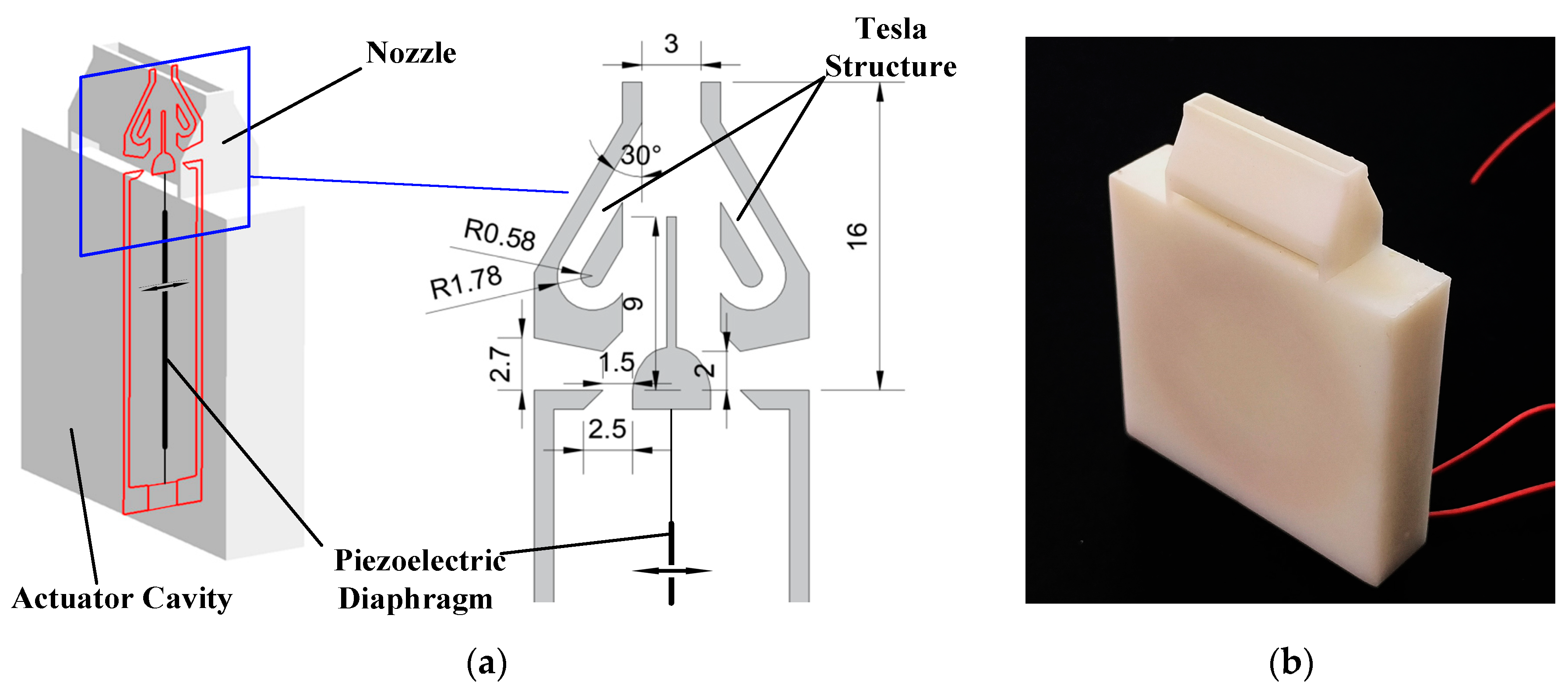
Figure 1. Structure of the novel micropump: (a) the interior structure and specific parameters; (b) the appearance of the material object.
Actuators 12 00226 g001
Figure 2. The working mechanism of the micropump: (a) first half cycle; (b) second half cycle.
Actuators 12 00226 g002
Figure 3. Two−dimensional numerical model.
Actuators 12 00226 g003
Figure 4. Instantaneous flow rate curves under different mesh quantities.
Actuators 12 00226 g004
Figure 5. Composition of PIV experimental system.
Actuators 12 00226 g005
Figure 6. The velocity and streamline of the flow field in the simulation and the PIV diagram of the operation of the valveless micropump based on dual synthetic jets in one cycle: (a) 1/4T; (b) 1/2T; (c) 3/4T; (d) 1T.
Actuators 12 00226 g006aActuators 12 00226 g006b
Figure 7. The velocity and streamline time−mean flow field of the micropump in one cycle: (a) overview of time−mean flow field; (b) partial view of time−mean flow field.
Actuators 12 00226 g007
Figure 8. Average velocity in the nozzle downstream: (a) velocity distribution of the downstream at different positions (−5 X 5, 0 H Y 18); (b) average velocity in the center line (X = 0, 0   H Y 18).
Actuators 12 00226 g008
Figure 9. Comparison of time−mean flow field: (a) simulation results with streamline; (b) PIV experiment.
Actuators 12 00226 g009
Figure 10. Comparison of velocity distribution between PIV and simulation results (−5 X 5, H Y = 3 ).
Actuators 12 00226 g010
Figure 11. Time−mean flow field of the micropump under different driving voltage amplitudes: (a) Case1; (b) Case2; (c) Case3; (d) Case4.
Actuators 12 00226 g011
Figure 12. The velocity magnitude of the flow field under different driving voltage amplitudes: (a) schematic diagram of line location; (b) velocity of flow field center (X = 0, 17 Y 40); (c) velocity distribution (−5 X 5, Y = 32).
Actuators 12 00226 g012
Figure 13. Structure of nozzle: (a) Tesla symmetrical nozzle; (b) shrink nozzle.
Actuators 12 00226 g013
Figure 14. Flow field and streamline of the shrink nozzle in one cycle: (a) 1/4T; (b) 1/2T; (c) 3/4T; (d) 1T.
Actuators 12 00226 g014
Figure 15. Instantaneous flow curves of the two structures.
Actuators 12 00226 g015
Table 1. Grid quantity and average flow rate.
Number of Grids Average   Flow   Rate   ( m 3 / s ) Difference from 400,000 Results (%)
60,0000.026324.74
130,0000.025672.15
240,0000.025360.92
400,0000.02513——
Table 2. Experimental voltage amplitude and angle parameters.
Experimental Serial NumberDriving Voltage Amplitude (±V)Influence Area Size (°)
Case115038.5
Case218040.5
Case321043.1
Case424042.2
Disclaimer/Publisher’s Note: The statements, opinions and data contained in all publications are solely those of the individual author(s) and contributor(s) and not of MDPI and/or the editor(s). MDPI and/or the editor(s) disclaim responsibility for any injury to people or property resulting from any ideas, methods, instructions or products referred to in the content.