Article

A Magnetic-Controlled Flexible Continuum Robot with Different Deformation Modes for Vascular Interventional Navigation Surgery

State Key Laboratory of Tribology in Advanced Equipment, Tsinghua University, Beijing 100084, China
*
Authors to whom correspondence should be addressed.
Actuators 2023, 12(6), 247; https://doi.org/10.3390/act12060247
Submission received: 4 May 2023 / Revised: 3 June 2023 / Accepted: 5 June 2023 / Published: 14 June 2023
(This article belongs to the Special Issue Soft Robotics in Biomedical Application)

Abstract

:
A magnetic-controlled flexible continuum robot (MFCR) is a kind of continuum robot with small-size and flexibility that deforms under controlled magnetic fields, which makes MFCRs easy to fit in special sizes and designs and provides them with the ability to feasibly arrive at the desired area through certain blood vessel bifurcation. The magnetic drive method is suitable for the miniaturization of soft continuum robots but shows limitations in realizing high flexibility. To achieve miniaturization and high flexibility, in this work, the deformation schemes of a magnetic-controlled flexible continuum robot (MFCR) are proposed, simulated, and experimentally validated. The proposed MFCR includes a soft steering part made of a silicone elastomer with uniformly dispersed NdFeB powder which has a specific magnetization direction. With the actuation of different magnetic fields, the proposed MFCR shows three different deformation modes (C-shape, J-shape, and S-shape) and high flexibility. By using the potential energy model combined with magnetic and elastic potential energy, the quasi-static deformation model of MFCR is built. Through various simulations and experiments, we analyzed and predicted different deformation modes. The results from the experiments demonstrate the accuracy of the deformation model. The results indicate that the MFCR has good control precision and deformation performance with potential applications in robot-assisted minimally invasive surgery.

1. Introduction

Miniaturization [1,2,3,4,5] and flexibility [6,7,8] are the current goals of medical interventional navigation robots [9]. A small-scale robot can significantly decrease patients’ recovery times and reduce the size of wounds after minimally invasive surgery [10]. With more flexibility, interventional navigation robots can quickly reach the target spot during cardiovascular disease surgery by passing across blood vessel bifurcations [11,12,13].
At present, the conventional method to pass through a blood vessel is to use guidewires [14], which are made of metal materials with high biocompatibility [15], and the guidewire tip can be preshaped in a variety of ways to pass through blood vessel bifurcations. However, various issues could arise with this method, such as vessel perforation, breakage of the guidewire tip, twisting of the guidewire tip, or loss of the guidewire [16]. Most of them are rigid without flexibility, and the tip shape cannot be altered to accommodate changing conditions in real time [17,18,19]. In tortuous blood vessels, steering is achieved by manual control of the tip. Additionally, some loss is experienced during torque transmission to the distal end, which makes interventional navigation more difficult. Therefore, it is necessary to increase the flexibility of interventional navigation robots, which could adapt to the real-time surgical situation better.
At present, steerable guidewires and continuum robots (CR) offer alternative methods [20,21] to conventional interventional guidewires [22,23,24], which improve flexibility and maneuverability. Researchers have proposed many different manipulation and actuation methods, such as electric motors [25,26], cables [27,28,29], tendons [30], pneumatics [31], smart materials [32], magnetics [33,34,35], and hydraulics [36,37]. However, traditional continuum robots require extra mechanical devices or structures such as drive mechanisms or pneumatic chambers, which are difficult to miniaturize. To solve the problems mentioned above, magnetic driven soft continuum robots at the milli- and submillimetre scale have received significant attention [38,39,40]. Some researchers have inserted tiny magnets into elastic polymers to increase their flexibility [41,42] and utilized the magnetic field [43,44,45] for a simple structure and intuitive control. Soft continuum robots deform by the force and torque generated by external permanent magnets or uniform magnetic fields. For example, Daojing Lin et al. [42] proposed a continuum robot with a permanent magnet coupled to the tip and optimized the effective workspace. However, it is well known that the size of the magnetic material limits the magnetic strength which further affects the stiffness and miniaturization of soft continuum robots. If small-sized permanent magnets were used for interventional navigation, it would cause the limitation of miniaturization, which becomes a contradiction [46,47].
Therefore, to solve this problem several studies have explored ways to realize the miniaturization of continuum robots [48,49,50], such as mixing micron magnetic powder in polymer materials [51] to replace the permanent magnet which is the limitation of miniaturization. This solution realized the miniaturization of magnetic continuum robots, but the improvement of the flexibility needs to be achieved.
Therefore, researchers have attempted to improve the flexibility of continuum robots while maintaining the miniaturization of magnetic-controlled continuum robots. Recently, programmable magnetization technology [40] has been used to enhance robots’ dexterity [1,52,53,54]. Hu Wenqi et al. [6] mixed hard magnetic microparticles with silicone elastomer and created a soft robot with a single-wavelength harmonic magnetization, which realized multimodal locomotion and improved the flexibility. Giovanni Pittiglio et al. proposed a magnetic programmable catheter with unsymmetrical magnetization to cause different deformation and adapt to the surrounding anatomy during navigation [55]. However, since the magnetic programmable catheter has difficulty miniaturizing, it is hard for it to be applied to narrow and complex environments and structures. In addition, the quasi-static deformation analysis and prediction is also insufficient.
In this work, we proposed a magnetic-controlled flexible continuum robot (MFCR) to realize miniaturization and flexibility by designing various deformation modes (Figure 1a). The MFCR was accomplished by creating a magnetic–elastic composite material and programming its magnetization, which made it suitable to steer in the narrow blood vessel bifurcations. On the other hand, to describe the proposed MFCR’s deformation modes under quasi-static conditions, the magnetic potential energy and elastic potential energy were coupled to build a potential energy model for quasi-static deformation analysis and prediction. Numerical simulation and experiments were used to confirm the deformation prediction of the MFCR, which showed that the deformation control of the MFCR could be realized well by uniform magnetic fields. Different deformation modes were simultaneously devised to make it more flexible to reach the desired area through blood vessel bifurcation. Furthermore, several in vitro experimental test setups were designed to confirm the deformability, based on physiological structure characteristics of the aorta and coronary artery. It is expected that MFCRs with different deformation modes can be applied in more minimally invasive surgery situations, such as complex blood vessels.

2. Magnetic-Controlled Flexible Continuum Robot with Different Deformation Modes

2.1. Deformation Principle of the Magnetic-Controlled Flexible Continuum Robot

The performance of the MFCR depends on its material characteristics, structure, and magnetic field. The magnetic material in the elastic composite material generates torque τ via magnetic field B [56], so that the magnetic moment direction of the magnetic material inside points to the direction of the magnetic field. The torque is described as (1):
τ = m × B
where m is the magnetic moment of the magnetic material and B is the magnetic flux density of the magnetic field. In this work, torque is used to drive the MFCR, achieving deformation and navigation function. In order to predict the deformation of the MFCR, a simplified model based on total potential energy was proposed to describe the deformation of the MFCR in the magnetic field. The MFCR was simplified to the Euler–Bernoulli beam model, and magnetic potential energy [57,58], and elastic potential energy was integrated into the total potential energy (gravitational potential energy is disregarded) to explain the effects of the magnetic field on the magnetic–elastic composite material, and the governing equation of the deformation of the MFCR was derived. By resolving the deformation governing equation, the equation of MFCR deformation under the magnetic field may be determined.
The total potential energy in the magnetic field is divided into two parts, which are described as:
W m a g n e t i c = 1 μ 0 B r B d V
W e l a s t i c = 1 2 ( E ε 2 + M θ ) d V
where μ 0 is the vacuum permeability, B r is the magnetic moment of the magnetic materials, B is the magnetic flux density of the external magnetic field, E is the elastic modulus of the MFCR, ε is the strain of the MFCR, M is the combined moment, and θ is the midline section angle of the MFCR.
The total potential energy of the MFCR can be described as:
W = W m a g n e t i c + W e l a s t i c
For the MFCR, deformation can be considered in a 2D plane, combined with the minimum potential energy principle. The differential equation of the MFCR deformation can be described as:
W = 0
E ε 1 μ 0 B r B cos ( θ - α ) = 0
E I d 2 θ d x 2 A μ 0 B r B ( ε + 1 ) sin ( θ - α ) = 0
where α is the angle between the direction of the magnetic field and the magnetic moment, I is the cross-sectional moment of the inertia, and A is cross-sectional area of the MFCR. The angle-position relationship of MFCR can be obtained by solving Equations (6) and (7).

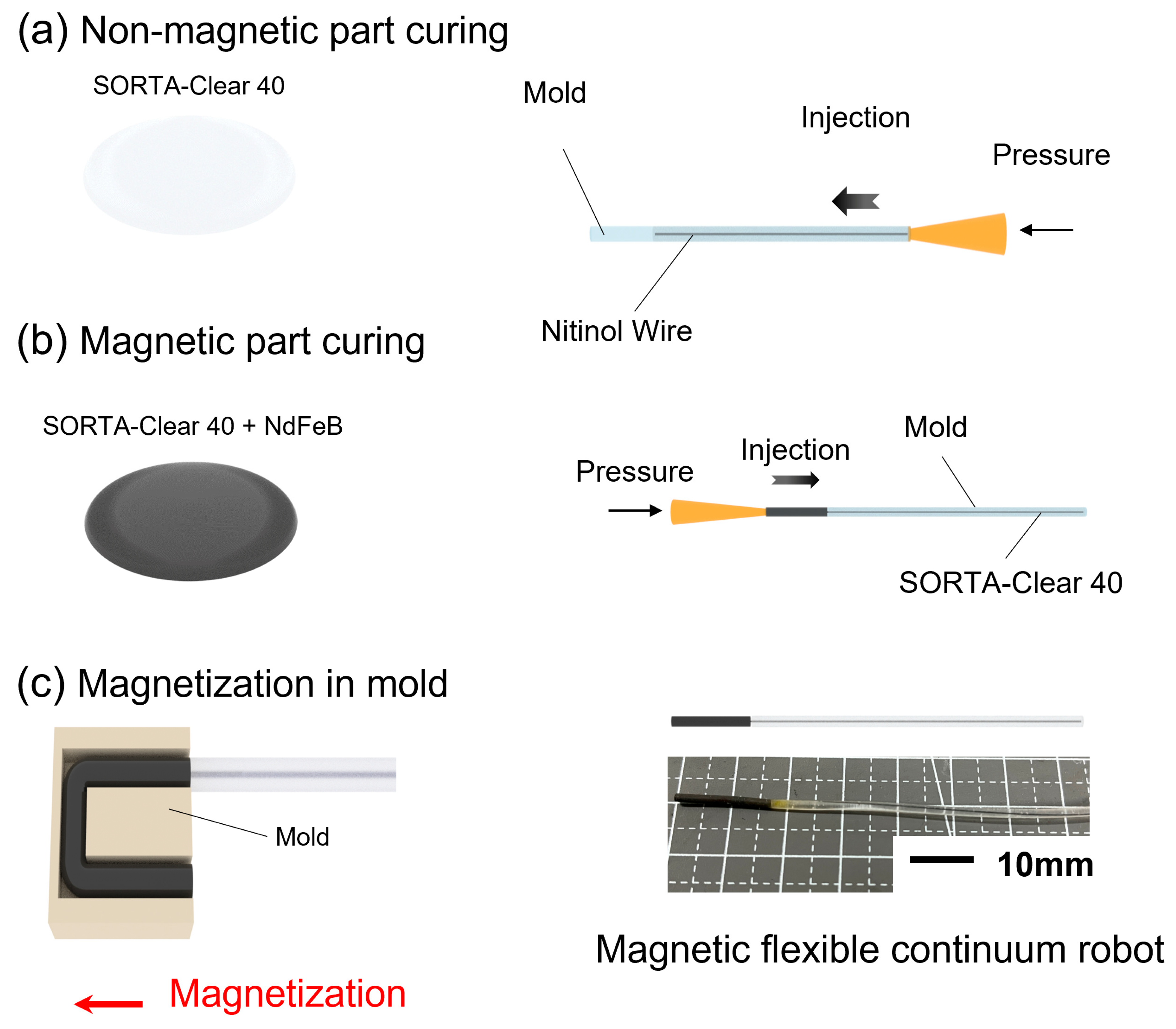
2.2. Manufacture of the Magnetic-Controlled Flexible Continuum Robot

Ferromagnetic materials are magnetized under the influence of a magnetic field. Ferromagnetic materials can sustain high residual magnetization and coercivity even in the absence of an external magnetic field, enabling them to produce magnetic fields on their own. The MFCR was constructed using magnetic–elastic composites, including NdFeB powder and silicone elastomer. The MFCR consisted of a magnetic soft part and a non-magnetic soft part. The initial step in the preparation process was to prepare the non-magnetic soft part by filling uncured silicone elastomer into a hollow tubular mold by injection (Figure 2a). A core wire (nitinol wire) was used in the mold to increase the stiffness of the non-magnetic soft part. When the injection process was completed, the core wire was fixed inside the non-magnetic soft part after being cured at 24 °C for 16 h. After the non-magnetic soft part was cured, SORTA-Clear 40 (Smooth-On, Macungie, PA, USA) was uniformly mixed with NdFeB powder (particle size 5 μm) of the specific mass ratio 1:1 using a mechanical mixer for 10 min. Then, the mixture was injected into a reserved mold position (Figure 2b). The magnetic part and the non-magnetic part were linked by the bonding force between the silicone elastomer and cured at 24 °C for 16 h. After the curing process was finished, the MFCR was separated from the flexible tubular mold, and the magnetic part of the MFCR was constrained by a 3D-printed mold to actualize the design of the magnetization direction (Figure 2c). An electromagnet that was able to produce a 1.5 T uniform magnetic field was used to finish the magnetization procedure of the MFCR. The magnetization procedure lasted for 10 s. Finally, the proposed MFCR with specific magnetization direction can be obtained by removing the 3D-printed mold.

3. Control of the Magnetic-Controlled Flexible Continuum Robot

3.1. Deformation Simulation of the Magnetic-Controlled Flexible Continuum Robot

Based on the MFCR equations in Section 2.1, the deformation prediction of the MFCR was accomplished, and the deformation prediction platform was built by using MATLAB. A three-dimensional electromagnet platform was built to test the deformation of the MFCR, and the simulation prediction results were compared with the experimental results to verify its accuracy. Figure 3 displays the magnetization direction distribution of the magnetic part of the MFCR. Through this magnetization direction design, according to the effect of the magnetic field and magnetic moment in Section 2.1, when the magnetic field is given in the opposite direction, the middle section will produce asymmetric deformation. It is hoped that this will result in asymmetrical deformation and expand the MFCR’s deformation modes.
The length of magnetic part is L = 15 mm and the diameter is D = 1.5 mm. One side of the MFCR was fixed to the support of the experimental platform on a three-dimensional electromagnet platform capable of producing a three-dimensional magnetic field. Using a DSLR camera, the robot’s static deformation in the presence of a magnetic field was examined. The experimental results of the MFCR were measured by an image analysis program (Image J) based on the obtained images, which are shown in Figure 4.

3.2. Deformation Ability of the Magnetic-Controlled Flexible Continuum Robot

In addition to the two deformation modes above, in a large magnetic field, the MFCR showed C-shape deformation. The deformation angle of the MFCR was recorded by the DSLR camera to evaluate its deformation ability using 3D-printed narrow channels. The diameter of the channels was 4 mm. Ring channels with different angles of 30°–130° (30°, 50°, 60°, 70°, 90°, 110°, 120°, and 130°) were designed to test the turning ability of the MFCR. The process consisted of two steps. First, it was made to pass through a right-angled channel to remain stable, and then it was made to turn to a channel with specific angles. The test results are shown in Figure 5a below.
The results demonstrated that under the magnetic field created by a permanent magnet, the MFCR exhibited C-shape deformation. The capacity of the MFCR to pass through channels with varying angles of 30° to 130° by big angle bending deformation of the C-shape demonstrated that it had flexible turning ability and showed that it may be used to pass blood artery bifurcations at various angles.
In vascular interventional surgery, doctors use rigid guide wires to reach the human coronary artery for treatment (e.g., percutaneous transluminal coronary angioplasty). The angle between the aorta and coronary artery varies depending on the physiological and anatomical features of the human body. A specific mean value of angle is shown in Table 1. In order to show the deformation benefits of the MFCR in vascular interventional surgery, simplified models of aorta–coronary artery with three different angles were designed. The MFCR controlled by the permanent magnet was used to deform at blood vessel bifurcation, making its tip enter the bifurcation channel of blood vessels, and then gradually diminish the intensity of the magnetic field, making it gradually enter the bifurcation of blood vessels with the help of manual operation. Figure 5c shows the path of the MFCR through the aorta–left coronary artery and aorta–right coronary artery at varied angles.

3.3. Deformation in Different Situations of the Magnetic-Controlled Flexible Continuum Robot

During vascular interventional surgery, the guide wire may encounter obstructions such as thrombi or other adhesions on the vascular wall that make it more challenging to pass through the bifurcation of the vessel without trouble. For the MFCR, different deformation modes can be used to adapt to navigation in different conditions. According to Section 3.1, the MFCR can exhibit J-shape deformation (Figure 6a and Supplementary Video S1) and S-shape deformation (Figure 6b and Supplementary Video S2) when driven by magnetic fields in various directions. Two different types of obstructions were placed at the blood vessel bifurcation. As seen in Figure 6, the magnetic field caused the MFCR to distort in order to test its capacity to bypass obstacles and pass through the branch of blood arteries.

4. Discussion

Compared with robots driven by motors or pneumatics, the soft navigation robot proposed in this paper was controlled by a non-contact magnetic field, without extra space to place the motor or gas chamber to meet the deformation requirements, and the size of the robot was reduced, making it more suitable for use in minimally invasive navigation surgery.
The MFCR was made by a magnetic–elastic composite material. Compared with traditional interventional guidewires, soft silicone elastomer has a stiffness similar to biological tissues. Meanwhile, the nitinol wire, which is known as a biocompatible material, was wrapped with the silicone elastomer to prevent the nitinol wire from harming or injuring the vascular tissue.
The MFCR presented in this work utilized micron-sized ferromagnetic materials that were spread in the silicone elastomer to change it into a soft magnet with flexibility and deformability in contrast to traditional flexible robots that use small permanent magnets as the source of the internal magnetic moment. Correspondingly, the evenly dispersed micron ferromagnetic material provided the robot with a continuous and uniform distribution of magnetic moment and stiffness. A torque produced by the magnetic moment and external magnetic field was used to control the deformation of the MFCR.
For non-contact control, the MFCR deformed through the external magnetic field. Less than 150 mT of magnetic field was utilized in the experiment; thus, there would be no negative effects on the human body. In addition, it has been demonstrated that the silicone elastomer could be utilized directly on human skin without causing biological toxicity, which enhanced the biocompatibility and biosecurity of the MFCR.
Permanent magnets can generate a large gradient magnetic field and improve the deflection ability of soft continuum robots. An external uniform magnetic field in the desired direction is able to transmit the magnetic torque accurately, which makes the proposed MFCR deflect in different shapes. In addition, it has the advantage to use a three-dimensional electromagnet platform for accurate control of the magnetic field’s direction and accurate control of the MFCR. Therefore, the asymmetrical deformation modes of the proposed MFCR have been shown, and it has been demonstrated that the proposed MFCR is suitable for application in robot-assisted minimally invasive surgery.
Combining the magnetic potential energy and elastic potential energy in the Euler–Bernoulli beam model, a simulation model for forecasting the deformation of the MFCR was built. The model was verified by comparing the experimental results with the simulation results. Compared with existing magnetic robots embedded with small magnets, the MFCR proposed in this paper increased its flexibility through uniformly dispersed magnetic materials. The elasticity modulus is close to that of silicone elastomer which improved the safety in the process of interventional navigation. Additionally, a continuum model may predict continuous deformation more accurately and can reduce the distortion and eccentricity in deformation brought on by a discontinuous distribution of magnets.
By designing and editing the magnetization direction by using a mold, it is hoped for a magnetic-controlled flexible continuum robot with asymmetrical deformation modes to be obtained through the asymmetrical distribution of magnetization direction. According to the current magnetization direction distribution design, when magnetic fields with different directions were given, the MFCR showed different deformation modes, as shown in Figure 4.
With the increase in the magnetic field, the magnetic part of the MFCR gradually showed C-shape deformation (Figure 4a), which is a common deformation mode for a continuum navigation robot. By creating a magnetic field at a 45-degree angle, the end and the tip of the MFCR point toward the direction of the magnetic field. It can deflect the MFCR in a C-shape. Figure 4a shows the bending experimental result of the MFCR when the externally uniform magnetic field is changed from 19.7 mT to 127 mT. Figure 4a(iii) shows the bending angle of the simulation results and the experimental results. From the experimental results, the MFCR shows C-shape deformation and covers a steering range of about 93.2°. In addition, the simulation results agree well with the experimental results within a mean error of about 2.979°. Figure 4a(iv) demonstrates the tip position of the simulation results and the experimental results. Similarly, the simulation results showed good agreement with the experimental results within a mean error of about 0.145 mm. It is believed that the deformation shown by this magnetic moment distribution would create favorable effects while passing through the bifurcation of blood vessels, which can help the MFCR for navigation use.
Apart from the C-shape, the MFCR can also realize J-shape and S-shape deformation With the increase in the magnetic field (19.7 mT–127 mT) at a minus 90 degree angle, MFCR gradually showed J-shape deformation (Figure 4b). The MFCR deformed in a J-shape can deflect from 0° to 66.6°. By setting the magnetic field with the configuration in Figure 4b(ii), the tip part obtains a larger magnetic torque than the end part, which results in J-shape deformation. Two bending angles (α1 and α2) were denoted to conduct quantitative analysis of the J-shape. In addition, the tip position was also considered to measure the error of the simulation and experimental results. Figure 4b(iii) shows the bending angle of the simulation results and the experimental results. The simulation results showed good agreement with experimental results. The mean error of angles is about 0.555° (α1) and 2.309° (α2), and the mean error of the tip position is about 0.328 mm. The MFCR can actively deform into a J-shape, which can help the MFCR to navigate and pass through the sharp bifurcation of the blood vessels.
With the increase in the magnetic field (19.7 mT–127 mT) at a 135 degree angle, the MFCR gradually showed S-shape deformation (Figure 4c). In S-shape deformation mode, the MFCR deflects with opposite curvature directions on the two sides of the beam. When the external magnetic field is set with the configuration in Figure 4b(ii), the tip part and the end part obtain opposite magnetic torques and they have a similar curvature radius. Due to the magnetic torque contribution of the middle part, the tip part obtains a slightly larger curvature radius than the end part. The parameters for the quantitative analysis are the same as the J-shape, which are shown in Figure 4c(iii,iv). Similarly, the simulation results showed good agreement with the experimental results. The mean error of angles is about 0.589° (α1) and 0.499° (α2), and the mean error of the tip position is about 0.103 mm. For mode S, the curvature of the end and tip can be varied by adjusting the direction of the magnetic field. In this deformation mode, the MFCR can be controlled to bypass the obstacle and arrive at its back end.
The deformation test demonstrated that the MFCR can be controlled by both permanent magnets and electromagnets. Combined with the physiological and anatomical characteristics of the aorta–coronary artery, narrow ring channels with different angles from 30° to 130° were designed, and the MFCR’s ability to turn was verified by using the permanent magnet to produce C-shape deformation (Figure 5a) with a large turning radius. To prove the potential of the MFCR for application in the surgical environment better, three simplified models with different angles were designed according to the structural characteristics of the aorta–coronary artery (Figure 5b). In the simulated vascular channel, bending deformation made the MFCR enter the branch blood vessel. Flexible control of the MFCR reduced the turning time by adjusting the position and direction of the permanent magnets that were held in the operator’s hands or installed on a robot arm. The balance between accuracy and economy can also lower the overall operating and surgical costs, including time and money costs.
The three-dimensional electromagnetic platform generates a controllable magnetic field. Based on the experiments and simulations in Section 3.1, the MFCR deflected in the J-shape to pass through the blood vessels. J-shape deformation generated a larger turning radius as shown in Figure 6a, which makes the MFCR able to bypass thrombosis obstacles adhered to the outside of the main blood vessel and enter the next level of blood vessels. This shows the potential to solve the problem that traditional metal guide wires are unable to change their turning radius. Similarly, the MFCR deflected in the S-shape by the actuation of the magnetic field at the specific angle. Because of the magnetization design, the tip of the MFCR obtained a slightly larger curvature radius than the end part. This mode S could adapt to thrombosis obstacles sticking at the top or right vascular wall as shown in Figure 6b. Utilizing various deformation shapes is anticipated to increase surgical safety by lowering friction-damage-related problems after interventional navigation surgery.

5. Conclusions

In this study, in order to improve the flexibility of the soft continuum robot while maintaining the advantage of miniaturization, we proposed the MFCR. The flexibility and applicability of the MFCR were verified under the control of the permanent magnet and a three-dimensional electromagnetic platform. Through simulations and experiments, the characterization of the MFCR was executed. It was demonstrated that the simulation results showed good agreement with the experimental results. The maximum mean error of angles was about 2.979°, and the maximum mean error of the tip position was about 0.328 mm. The results showed that the MFCR’s multi-mode deformation was preliminarily verified with external magnetic fields in various directions, which had the potential to be applied to different vascular surgery situations. However, the current simulation model is still in the 2D plane. During the deformation prediction and multi-mode deformation experiments, the motion of the robot was limited to the 2D plane, and the magnetic field was also in the robot motion plane. In addition, during the deformation prediction test, the end of the robot was fixed, which affects its motion. Therefore, it is anticipated that the robot’s boundary conditions and the deformation model in 3D space will be solved in the future.

Supplementary Materials

The following supporting information can be downloaded at: https://www.mdpi.com/article/10.3390/act12060247/s1. Video S1: J-shape deformation, Video S2: S-shape deformation.

Author Contributions

Conceptualization, Z.W. and J.W.; methodology, Z.W.; software, Z.W. and Z.L.; validation, Y.M., L.C. and D.W.; formal analysis, Z.W.; investigation, Z.L.; resources, D.W.; data curation, Z.W. and Z.L.; writing—original draft preparation, Z.W.; writing—review and editing, Z.W. and D.W.; visualization, L.C. and Y.M.; supervision, D.W.; project administration, J.W.; funding acquisition, J.W. All authors have read and agreed to the published version of the manuscript.

Funding

This research was supported by the National Natural Science Foundation of China (NSFC) (Grant No. 52275200) and the National Natural Science Foundation of China (NSFC) (Grant No. 52205312).

Conflicts of Interest

The authors declare no conflict of interest.

References

  1. Kim, Y.; Yuk, H.; Zhao, R.; Chester, S.A.; Zhao, X. Printing ferromagnetic domains for untethered fast-transforming soft materials. Nature 2018, 558, 274–279. [Google Scholar] [CrossRef] [PubMed]
  2. Zhang, C.; Wang, W.; Xi, N.; Wang, Y.; Liu, L. Development and future challenges of bio-syncretic robots. Engineering 2018, 4, 452–463. [Google Scholar] [CrossRef]
  3. Yang, J.; Zhang, C.; Wang, X.; Wang, W.; Xi, N.; Liu, L. Development of micro-and nanorobotics: A review. Sci. China Technol. Sci. 2019, 62, 1–20. [Google Scholar] [CrossRef]
  4. Yang, G.-Z.; Fischer, P.; Nelson, B. New materials for next-generation robots. Sci. Robot. 2017, 2, eaap9294. [Google Scholar] [CrossRef]
  5. Yang, G.-Z.; Bellingham, J.; Dupont, P.E.; Fischer, P.; Floridi, L.; Full, R.; Jacobstein, N.; Kumar, V.; McNutt, M.; Merrifield, R. The grand challenges of Science Robotics. Sci. Robot. 2018, 3, eaar7650. [Google Scholar] [CrossRef]
  6. Hu, W.; Lum, G.Z.; Mastrangeli, M.; Sitti, M. Small-scale soft-bodied robot with multimodal locomotion. Nature 2018, 554, 81–85. [Google Scholar] [CrossRef]
  7. Ilami, M.; Ahmed, R.J.; Petras, A.; Beigzadeh, B.; Marvi, H. Magnetic needle steering in soft phantom tissue. Sci. Rep. 2020, 10, 2500. [Google Scholar] [CrossRef] [Green Version]
  8. Chautems, C.; Tonazzini, A.; Boehler, Q.; Jeong, S.H.; Floreano, D.; Nelson, B.J. Magnetic continuum device with variable stiffness for minimally invasive surgery. Adv. Intell. Syst. 2020, 2, 1900086. [Google Scholar] [CrossRef] [Green Version]
  9. Jager, E.W.H.; Inganäs, O.; Lundström, I. Microrobots for Micrometer-Size Objects in Aqueous Media: Potential Tools for Single-Cell Manipulation. Science 2000, 288, 2335–2338. [Google Scholar] [CrossRef]
  10. Lee, S.; Lee, S.; Kim, S.; Yoon, C.-H.; Park, H.-J.; Kim, J.-Y.; Choi, H. Fabrication and Characterization of a Magnetic Drilling Actuator for Navigation in a Three-dimensional Phantom Vascular Network. Sci. Rep. 2018, 8, 3691. [Google Scholar] [CrossRef] [Green Version]
  11. Nelson, B.J.; Kaliakatsos, I.K.; Abbott, J.J. Microrobots for minimally invasive medicine. Annu. Rev. Biomed. Eng. 2010, 12, 55–85. [Google Scholar] [CrossRef] [PubMed] [Green Version]
  12. Sitti, M.; Ceylan, H.; Hu, W.; Giltinan, J.; Turan, M.; Yim, S.; Diller, E. Biomedical Applications of Untethered Mobile Milli/Microrobots. Proc. IEEE 2015, 103, 205–224. [Google Scholar] [CrossRef] [PubMed]
  13. Sitti, M. Voyage of the microrobots. Nature 2009, 458, 1121–1122. [Google Scholar] [CrossRef]
  14. Ivar Seldinger, S. Catheter replacement of the needle in percutaneous arteriography: A new technique. Acta Radiol. 2008, 49, 47–52. [Google Scholar] [CrossRef] [PubMed]
  15. Louvard, Y.; Lefèvre, T.; Morice, M.-C. Percutaneous coronary intervention for bifurcation coronary disease. Heart 2004, 90, 713–722. [Google Scholar] [CrossRef] [PubMed] [Green Version]
  16. Khasawneh, F.A.; Smalligan, R.D. Guidewire-related complications during central venous catheter placement: A case report and review of the literature. Case Rep. Crit. Care 2011, 2011, 287261. [Google Scholar] [CrossRef]
  17. Roubin, G.S.; Yadav, S.; Iyer, S.S.; Vitek, J. Carotid stent-supported angioplasty: A neurovascular intervention to prevent stroke. Am. J. Cardiol. 1996, 78, 8–12. [Google Scholar] [CrossRef]
  18. Levin, D.C.; Rao, V.M.; Parker, L.; Bonn, J.; Maitino, A.J.; Sunshine, J.H. The changing roles of radiologists, cardiologists, and vascular surgeons in percutaneous peripheral arterial interventions during a recent five-year interval. J. Am. Coll. Radiol. 2005, 2, 39–42. [Google Scholar] [CrossRef]
  19. Jones, W.S.; Mi, X.; Qualls, L.G.; Vemulapalli, S.; Peterson, E.D.; Patel, M.R.; Curtis, L.H. Trends in settings for peripheral vascular intervention and the effect of changes in the outpatient prospective payment system. J. Am. Coll. Cardiol. 2015, 65, 920–927. [Google Scholar] [CrossRef] [Green Version]
  20. Dupont, P.E.; Simaan, N.; Choset, H.; Rucker, C. Continuum Robots for Medical Interventions. Proc. IEEE Inst. Electr. Electron. Eng. 2022, 110, 847–870. [Google Scholar] [CrossRef]
  21. Russo, M.; Sadati, S.M.H.; Dong, X.; Mohammad, A.; Walker, I.D.; Bergeles, C.; Xu, K.; Axinte, D.A. Continuum Robots: An Overview. Adv. Intell. Syst. 2023, 5, 2200367. [Google Scholar] [CrossRef]
  22. Ghoreishi, S.F.; Sochol, R.D.; Gandhi, D.; Krieger, A.; Fuge, M. Bayesian Optimization for Design of Multi-Actuator Soft Catheter Robots. IEEE Trans. Med. Robot. Bionics 2021, 3, 725–737. [Google Scholar] [CrossRef] [PubMed]
  23. Phelan Iii, M.F.; Tiryaki, M.E.; Lazovic, J.; Gilbert, H.; Sitti, M. Heat-Mitigated Design and Lorentz Force-Based Steering of an MRI-Driven Microcatheter toward Minimally Invasive Surgery. Adv. Sci. 2022. [Google Scholar] [CrossRef]
  24. Gunduz, S.; Albadawi, H.; Oklu, R. Robotic devices for minimally invasive endovascular interventions: A new dawn for interventional radiology. Adv. Intell. Syst. 2021, 3, 2000181. [Google Scholar] [CrossRef]
  25. Wang, T.; van Soest, G.; van der Steen, A.F.W. A micromotor catheter for intravascular optical coherence tomography. Engineering 2015, 1, 15–17. [Google Scholar] [CrossRef] [Green Version]
  26. Hou, S.; Li, Y.; Zou, C.; Li, Y.; Tang, H.; Liu, Z.; Chen, S.; Peng, J. A Novel Distal Micromotor-Based Side-Looking Intravascular Ultrasound Transducer. IEEE Trans. Ultrason. Ferroelectr. Freq. Control. 2021, 69, 283–290. [Google Scholar] [CrossRef] [PubMed]
  27. Wang, H.; Yang, X.; Zheng, X.; Du, N.; Zhen, H.; Hou, Z. Design and Analysis for Minimally Invasive Vascular Interventional Surgical Robot System. Adv. Sci. Lett. 2012, 8, 31–36. [Google Scholar] [CrossRef]
  28. Wang, K.; Lu, Q.; Chen, B.; Shen, Y.; Li, H.; Liu, M.; Xu, Z. Endovascular intervention robot with multi-manipulators for surgical procedures: Dexterity, adaptability, and practicability. Robot. Comput. -Integr. Manuf. 2019, 56, 75–84. [Google Scholar] [CrossRef]
  29. Ai, X.; Gao, A.; Lin, Z.; He, C.; Chen, W. A Multi-Contact-Aided Continuum Manipulator with Anisotropic Shapes. IEEE Robot. Autom. Lett. 2021, 6, 4560–4567. [Google Scholar] [CrossRef]
  30. Sun, Y.; Liu, Y.; Lueth, T.C. Optimization of Stress Distribution in Tendon-Driven Continuum Robots Using Fish-Tail-Inspired Method. IEEE Robot. Autom. Lett. 2022, 7, 3380–3387. [Google Scholar] [CrossRef]
  31. Tutcu, C.; Baydere, B.A.; Talas, S.K.; Samur, E. Quasi-static modeling of a novel growing soft-continuum robot. Int. J. Robot. Res. 2021, 40, 86–98. [Google Scholar] [CrossRef]
  32. Couture, T.; Szewczyk, J. Design and experimental validation of an active catheter for endovascular navigation. J. Med. Devices 2018, 12, 011003. [Google Scholar] [CrossRef] [Green Version]
  33. Dehrouyeh-Semnani, A.M. Nonlinear geometrically exact dynamics of fluid-conveying cantilevered hard magnetic soft pipe with uniform and nonuniform magnetizations. Mech. Syst. Signal Process. 2023, 188, 110016. [Google Scholar] [CrossRef]
  34. Kim, Y.; Genevriere, E.; Harker, P.; Choe, J.; Balicki, M.; Regenhardt, R.W.; Vranic, J.E.; Dmytriw, A.A.; Patel, A.B.; Zhao, X. Telerobotic neurovascular interventions with magnetic manipulation. Sci. Robot. 2022, 7, eabg9907. [Google Scholar] [CrossRef] [PubMed]
  35. Zrínyi, M.; Barsi, L.; Büki, A. Deformation of ferrogels induced by nonuniform magnetic fields. J. Chem. Phys. 1996, 104, 8750–8756. [Google Scholar] [CrossRef]
  36. Kumar, N.; Wirekoh, J.; Saba, S.; Riviere, C.N.; Park, Y.-L. Soft miniaturized actuation and sensing units for dynamic force control of cardiac ablation catheters. Soft Robot. 2021, 8, 59–70. [Google Scholar] [CrossRef]
  37. Guo, Z.; Dong, Z.; Lee, K.-H.; Cheung, C.L.; Fu, H.-C.; Ho, J.D.L.; He, H.; Poon, W.-S.; Chan, D.T.-M.; Kwok, K.-W. Compact design of a hydraulic driving robot for intraoperative MRI-guided bilateral stereotactic neurosurgery. IEEE Robot. Autom. Lett. 2018, 3, 2515–2522. [Google Scholar] [CrossRef]
  38. Martin, J.W.; Scaglioni, B.; Norton, J.C.; Subramanian, V.; Arezzo, A.; Obstein, K.L.; Valdastri, P. Enabling the future of colonoscopy with intelligent and autonomous magnetic manipulation. Nat. Mach. Intell. 2020, 2, 595–606. [Google Scholar] [CrossRef]
  39. Leong, F.; Garbin, N.; Natali, C.D.; Mohammadi, A.; Thiruchelvam, D.; Oetomo, D.; Valdastri, P. Magnetic Surgical Instruments for Robotic Abdominal Surgery. IEEE Rev. Biomed. Eng. 2016, 9, 66–78. [Google Scholar] [CrossRef]
  40. Bacchetti, A.; Lloyd, P.; Taccola, S.; Fakhoury, E.; Cochran, S.; Harris, R.A.; Valdastri, P.; Chandler, J.H. Optimization and fabrication of programmable domains for soft magnetic robots: A review. Front. Robot. AI 2022, 9, 1040984. [Google Scholar] [CrossRef]
  41. Jeon, S.; Hoshiar, A.K.; Kim, S.; Lee, S.; Kim, E.; Lee, S.; Kim, K.; Lee, J.; Kim, J.-Y.; Choi, H. Improving guidewire-mediated steerability of a magnetically actuated flexible microrobot. Micro Nano Syst. Lett. 2018, 6, 15. [Google Scholar] [CrossRef]
  42. Lin, D.; Wang, J.; Jiao, N.; Wang, Z.; Liu, L. A Flexible Magnetically Controlled Continuum Robot Steering in the Enlarged Effective Workspace with Constraints for Retrograde Intrarenal Surgery. Adv. Intell. Syst. 2021, 3, 2000211. [Google Scholar] [CrossRef]
  43. Yang, X.; Shang, W.; Lu, H.; Liu, Y.; Yang, L.; Tan, R.; Wu, X.; Shen, Y. An agglutinate magnetic spray transforms inanimate objects into millirobots for biomedical applications. Sci. Robot. 2020, 5, eabc8191. [Google Scholar] [CrossRef] [PubMed]
  44. Cui, J.; Huang, T.-Y.; Luo, Z.; Testa, P.; Gu, H.; Chen, X.-Z.; Nelson, B.J.; Heyderman, L.J. Nanomagnetic encoding of shape-morphing micromachines. Nature 2019, 575, 164–168. [Google Scholar] [CrossRef] [PubMed]
  45. Ze, Q.; Kuang, X.; Wu, S.; Wong, J.; Montgomery, S.M.; Zhang, R.; Kovitz, J.M.; Yang, F.; Qi, H.J.; Zhao, R. Magnetic shape memory polymers with integrated multifunctional shape manipulation. Adv. Mater. 2020, 32, 1906657. [Google Scholar] [CrossRef] [PubMed]
  46. Lin, D.; Jiao, N.; Wang, Z.; Liu, L. A Magnetic Continuum Robot with Multi-Mode Control Using Opposite-Magnetized Magnets. IEEE Robot. Autom. Lett. 2021, 6, 2485–2492. [Google Scholar] [CrossRef]
  47. Jeon, S.; Hoshiar, A.K.; Kim, K.; Lee, S.; Kim, E.; Lee, S.; Kim, J.-Y.; Nelson, B.J.; Cha, H.-J.; Yi, B.-J. A magnetically controlled soft microrobot steering a guidewire in a three-dimensional phantom vascular network. Soft Robot. 2019, 6, 54–68. [Google Scholar] [CrossRef] [Green Version]
  48. Xu, W.; Liu, T.; Li, Y. Kinematics, dynamics, and control of a cable-driven hyper-redundant manipulator. IEEE/ASME Trans. Mechatron. 2018, 23, 1693–1704. [Google Scholar] [CrossRef]
  49. Ouyang, B.; Liu, Y.; Tam, H.Y.; Sun, D. Design of an Interactive Control System for a Multisection Continuum Robot. IEEE/ASME Trans. Mechatron. 2018, 23, 2379–2389. [Google Scholar] [CrossRef]
  50. Renda, F.; Giorelli, M.; Calisti, M.; Cianchetti, M.; Laschi, C. Dynamic model of a multibending soft robot arm driven by cables. IEEE Trans. Robot. 2014, 30, 1109–1122. [Google Scholar] [CrossRef]
  51. Kim, Y.; Parada, G.A.; Liu, S.; Zhao, X. Ferromagnetic soft continuum robots. Sci. Robot. 2019, 4, eaax7329. [Google Scholar] [CrossRef]
  52. Li, Q.; Li, S.; Zhang, X.; Xu, W.; Han, X. Programmed magnetic manipulation of vesicles into spatially coded prototissue architectures arrays. Nat. Commun. 2020, 11, 232. [Google Scholar] [CrossRef] [PubMed] [Green Version]
  53. Lum, G.Z.; Ye, Z.; Dong, X.; Marvi, H.; Erin, O.; Hu, W.; Sitti, M. Shape-programmable magnetic soft matter. Proc. Natl. Acad. Sci. USA 2016, 113, E6007–E6015. [Google Scholar] [CrossRef] [PubMed] [Green Version]
  54. Dong, Y.; Wang, L.; Xia, N.; Yang, Z.; Zhang, C.; Pan, C.; Jin, D.; Zhang, J.; Majidi, C.; Zhang, L. Untethered small-scale magnetic soft robot with programmable magnetization and integrated multifunctional modules. Sci. Adv. 2022, 8, eabn8932. [Google Scholar] [CrossRef] [PubMed]
  55. Pittiglio, G.; Lloyd, P.; da Veiga, T.; Onaizah, O.; Pompili, C.; Chandler, J.H.; Valdastri, P. Patient-Specific Magnetic Catheters for Atraumatic Autonomous Endoscopy. Soft Robot. 2022, 9, 1120–1133. [Google Scholar] [CrossRef]
  56. Jiles, D. Introduction to Magnetism and Magnetic Materials; CRC Press: Boca Raton, FL, USA, 2015. [Google Scholar]
  57. Zhao, R.; Kim, Y.; Chester, S.A.; Sharma, P.; Zhao, X. Mechanics of hard-magnetic soft materials. J. Mech. Phys. Solids 2019, 124, 244–263. [Google Scholar] [CrossRef]
  58. Wang, L.; Kim, Y.; Guo, C.F.; Zhao, X. Hard-magnetic elastica. J. Mech. Phys. Solids 2020, 142, 104045. [Google Scholar] [CrossRef]
Figure 1. Schematic diagram of the magnetic-controlled flexible continuum robot (MFCR). (a) Schematic diagram of a partial artery in the heart region and the MFCR performing interventional navigation. Due to the complex vascular anatomy of the heart region, the flexibility of the robot is very important. The MFCR is controlled by the magnetic field without contact. (b) The MFCR generates C-shape deformation at different angles by using a permanent magnet. (i) The maximum angle of the MFCR was tested by a narrow ring model. (ii) The ability of the MFCR to pass through the coronary artery was verified by a simplified aorta–coronary artery model. (c) Electromagnetic system to perform deformation accuracy tests and turning tests which consisted of five orthogonal electromagnets and a camera to capture motion. The MFCR was placed on a testbed containing a model of a bifurcated vessel.
Actuators 12 00247 g001
Figure 2. Schematic diagram of the manufacturing process of the MFCR. (a) Preparation of the non-magnetic part of the MFCR by injection, which is inserted into the nitinol wire in the center to enhance the stiffness. (b) Preparation of the magnetic part of the MFCR by injection. (c) The MFCR magnetized in the uniform magnetic field generated by the electromagnet, and different positions of the MFCR with different magnetization directions. The red arrow represents the direction of magnetization.
Actuators 12 00247 g002
Figure 3. Magnetization direction design and distribution of the MFCR. The white arrows inside represent the direction of the magnetic moment inside the MFCR. L1 = 6 mm, L2 = 3 mm, and L3 = 6 mm.
Actuators 12 00247 g003
Figure 4. Analysis results of different deformation modes: (a) C-shape deformation, (i) schematic of the C-shape deformation, (ii) the bending angle is denoted as α, and the position of the tip is characterized by Vmax, (iii) bending angle of the simulation results and experimental results (n = 3), (iv) tip position of the simulation results and the experimental results (n = 3), (b) J-shape deformation, (i) schematic of the J-shape deformation, (ii) the bending angle is denoted as α1 and α2, and the position of the tip is characterized by Vmax, (iii) bending angle of the simulation results and the experimental results (n = 3), (iv) the tip position of the simulation results and the experimental results (n = 3), (c) S-shape deformation, (i) schematic of the S-shape deformation, (ii) the bending angle is denoted as α1 and α2, and the position of the tip is characterized by Vmax, (iii) the bending angle of the simulation results and the experimental results (n = 3), and (iv) the tip position of the simulation results and the experimental results (n = 3). The red arrow represents the direction of the external magnetic field.
Actuators 12 00247 g004
Figure 5. Schematic diagram of the testing deformability of the MFCR. (a) A permanent magnet was used to control the MFCR to produce C-shape deformation, and the robot passed through the narrow ring with angles of 30°, 50°, 60°, 70°, 90°, 110°, 120°, and 130° successively. (b) Schematic diagram of the anatomical features of the cardiac vascular region. (c) The permanent magnet guided the MFCR through the models of the aorta–coronary artery: (i) the obtuse angle, (ii) the right angle, and (iii) the acute angle.
Actuators 12 00247 g005
Figure 6. Schematic of the MFCR passing through the blood vessel bifurcation. (a) J-shape deformation to avoid the obstacle adhering to the side wall and to enter the branch blood vessel on the upper left smoothly: (i) approach to turning, (ii) J-shape deformation, (iii) bypassing the obstacle, and (iv) entering the branch blood vessel. (b) S-shape deformation to avoid the obstacle adhering to the vascular wall and to enter the branch blood vessel in the upper right smoothly: (i) approach to turning, (ii) S-shape deformation, (iii) bypassing the obstacle, and (iv) entering the branch blood vessel. An electromagnet system was used in this experiment to generate magnetic fields at various angles. Red ultralight clay was used as the possible obstacles (such as thrombus) in blood vessels. The white arrows show the magnetic field direction. Videos of the experiments are available in the Supplementary Materials.
Actuators 12 00247 g006
Table 1. Different types of aortic–coronary artery angle.
Typeα1α2
Acute Angle123.0°109.3°
Right Angle90.0°90.0°
Obtuse Angle72.0°65.0°
Disclaimer/Publisher’s Note: The statements, opinions and data contained in all publications are solely those of the individual author(s) and contributor(s) and not of MDPI and/or the editor(s). MDPI and/or the editor(s) disclaim responsibility for any injury to people or property resulting from any ideas, methods, instructions or products referred to in the content.

