1. Introduction
Road transportation using tank vehicles, distinguished by its large loading capacity and low transportation cost, serves as the main mode of transporting hazardous liquid chemicals in China [
1]. The tanker truck is a heavy-duty transportation vehicle with a specialized tank structure, with high bearing capacity, high center of gravity, and large volume. Under non-full load conditions and in complex operational scenarios, the tanker truck’s internal liquid is susceptible to significant oscillations, interacting intensively with the tank body. This interaction can alter the vehicle’s center of gravity, precipitating a drastic shift in the axle load, posing risks of tilting or even rolling over. These dynamics seriously undermine the operational safety and stability of the vehicle.
In order to reduce the occurrence of rollover accidents, many measures have been proposed to improve the lateral stability of tank vehicles. Yim et al. [
2,
3,
4,
5] controlled the active lateral stabilizer bar based on different control algorithms, using lateral load transfer rate as the control objective to reduce vehicle oscillation. Xu et al. [
6,
7] established an active steering-based anti-rollover control system for vehicles, which can effectively reduce the vehicle’s roll angle according to experimental results. Hu et al. [
8,
9,
10,
11] used the lateral-sway-angle speed as the control variable, and determined the additional lateral sway moment using different control calculation methods. They employed differential braking to apply the lateral sway moment, thereby controlling the vehicle’s stability. Through simulation experiments, they confirmed that such a method effectively suppresses the vehicle’s oscillation influence. However, the methods mentioned above have not effectively solved the contradiction between vehicle comfort and handling stability. Lateral stabilizer bars cannot adjust the roll-angle stiffness in real time, which may cause excessive vehicle roll during high-speed turning. Using differential braking and active steering not only introduces safety hazards during high-speed driving, but also contributes to driver fatigue and insecurity, negatively impacting the driving experience.
To address these issues, this paper proposes the use of controllable suspension technology to improve the driving stability of liquid tankers. The proposed controllable suspension can directly control the body sway of the liquid tanker, adjust the body posture in real time, and diminish the tank sway, all without compromising the driver’s experience. The proposition considers both the comfort and handling stability of the vehicle. Among controllable suspensions, the semi-active suspension has the advantages of low energy consumption, low cost, and similar control effect compared with the active suspension. Moreover, the electromagnetic semi-active suspension, which adopts the electromagnetic principle to change the damping characteristics of the damper, has a faster response speed and higher reliability. The electromagnetic semi-active suspension is composed of a sensor, an actuator, a controller, and a power supply. The sensors are designed to detect body posture and road information. The actuators, composed of electromagnetic actuators and dampers, along with the controller, are tasked with calculating the damping of the electromagnetic semi-active suspension. The controller sends control signals to the actuators, ensuring semi-active control of the suspension. When the electromagnetic linear actuator is inactive, the damper leverages hydraulic oil from the working cylinder and damping springs to achieve damping. Conversely, when the electromagnetic linear actuator is operational, the controller modifies the device’s electromagnetic impedance by altering the circuit equivalent resistance. This flexible adjustment of the suspension damping creates a controlled damping force, enabling semi-active control of the vehicle. By adopting electromagnetic semi-active suspension technology, the liquid tanker can attain enhanced driving stability and an enriched driving experience for the driver, while ensuring the comfort and handling stability of the vehicle. Such an advancement contributes significantly to reducing the risk associated with dangerous chemical transport accidents, thereby improving overall road safety.
2. Working Characteristics of Electromagnetic Semi-Active Suspension
2.1. Structural Principle of Electromagnetic Semi-Active Suspension
The suspension system is a key component of the vehicle and an important device to ensure the smooth running and stable handling of the vehicle. Passive suspension refers to the suspension whose stiffness and damping coefficient do not change with the external state. Semi-active suspension is a controllable suspension system that can adjust damping parameters to improve vehicle ride comfort and stability. Compared with semi-active suspension, passive suspension has the advantages of a simple structure and low cost. However, there is no energy supply device in the passive suspension system, and its stiffness and damping cannot be artificially controlled and adjusted during the driving process, so it is difficult for the passive suspension to take into account the requirements of vehicle driving, comfort, and handling stability, and it is increasingly unable to meet the high performance and high-energy efficiency needs of the rapid development of vehicle technology. Therefore, electromagnetic semi-active suspension technology has gradually become a research hotspot.
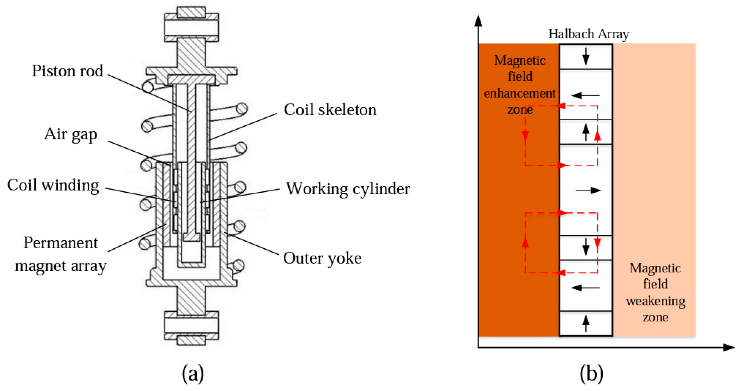
As shown in
Figure 1a, the electromagnetic semi-active suspension device is mainly composed of an outer magnetic yoke, a permanent magnet, a moving coil, and an inner core. The shock absorber piston rod is used as the inner yoke of the electromagnetic semi-active suspension, wherein the coil skeleton is fixed to the piston rod. When the suspension vibration and shock absorber piston reciprocate, the shock absorber will follow the synchronous movement of the coil, and cut off the magnetic induction line to generate an induction current. The generated induction current can be used to supply the semi-active control of the device, but also can be stored for other electrical equipment’s energy supply.
The electromagnetic semi-active suspension used in this paper is based on a cylindrical damper structure, with the addition of an electromagnetic linear actuator. The electromagnetic linear actuator is embedded in the suspension damper, as shown in
Figure 1a [
12]. The permanent magnet of the electromagnetic actuator adopts the Halbach array structure [
13,
14], which can effectively improve the electromagnetic characteristics of the device, as shown in
Figure 1b. The left side of the Halbeck array is the area where the field is enhanced, which is also the area where the coil is active, which can generate a greater induced current, and on the right side is the area where the field is weakened.
The electromagnetic semi-active suspension retains the traditional suspension’s piston hydraulic cylinder, which can passively absorb shock through the hydraulic cylinder. In addition, an added electromagnetic linear actuator can also provide semi-active control of the vehicle body. During semi-active control, the vehicle control module executes a preset suspension control strategy based on the vehicle’s posture as detected by sensors. By controlling a supercapacitor to provide a corresponding current to the electromagnetic linear actuator, the electromagnetic damping force of the actuator is adjusted to improve the vehicle’s posture and enhance driving stability.
Therefore, the electromagnetic damping force can be expressed by the thrust coefficient and the back electromotive force coefficient of the electromagnetic actuator. In electromagnetic semi-active suspension, the thrust coefficient of the electromagnetic actuator is denoted as
; the back electromotive force coefficient of the electromagnetic actuator is denoted as
. Therefore, the electromagnetic damping force can be expressed as follows:
Let the damping of the electromagnetic actuator be denoted as
. Then, the electromagnetic damping force of the electromagnetic semi-active suspension can be written as:
2.2. Control Strategy for Electromagnetic Semi-Active Suspension
For a more refined analysis of the driving dynamics of a tanker truck, the vehicle is abstracted into a seven degree of freedom model, as depicted in
Figure 2. This model thoroughly considers the vibration characteristics of the tanker truck body in vertical, pitch, and roll directions. It also takes into account the vertical vibration characteristics of the four electromagnetic semi-active suspensions bridging the vehicle body. To mitigate body vibrations in the vertical, pitch, and lateral tilt directions, this paper employs a fuzzy control method [
15,
16] for adjusting the damping of the electromagnetic semi-active suspension. Characterized by its adaptability and robustness, fuzzy control effectively addresses the challenges posed by the electromagnetic semi-active suspension in maintaining liquid tanker stability.
According to Newton’s second law, the dynamic equation of the mass on the vehicle spring is as follows:
The dynamic equations for the four suspensions are as follows:
where
and
represent the sprung mass of the vehicle and the unsprung mass of the four wheels, respectively;
represents the vertical displacement of the vehicle body;
and
represent the pitch and roll angles, respectively;
and
represent the roll and pitch moments of inertia of the vehicle, respectively;
,
and
represent the passive damping force, spring force, and tire stiffness coefficient of each suspension, respectively;
represents the displacement of each suspension mass;
represents the road roughness excitation;
represents the vibration control force in the vertical direction;
represent the roll and pitch vibration moments of the vehicle body, respectively;
and
represent the wheelbase and track width of the tanker truck, respectively;
represents the distance from the center of mass of the tanker truck to the front axle;
represents the distance from the center of mass of the tanker truck to the wheels;
represents the control force of each electromagnetic semi-active suspension.
Given the interference between the control forces of the four suspensions on the vehicle body during actual driving, and the intertwined control objectives during the control process, direct adjustments to the control forces of the four suspensions may not yield significant control effects. Therefore, this paper first designs three fuzzy controllers to suppress the vibration of the liquid tanker truck body in the vertical, pitch, and roll directions, respectively. Subsequently, the requisite control forces and moments of the fuzzy controllers are equivalently calculated and allocated as the damping forces for the four electromagnetic semi-active suspensions. Finally, these suspensions feed the corresponding damping forces into the vehicle model, enabling comprehensive control of the vehicle’s motion. The principle of this control strategy is shown in
Figure 3.
The damping forces of the four suspensions can be calculated using the following moment-allocation formula:
3. Construction of the Vehicle Model for the Hazardous Chemical Liquid Tanker Truck
This paper studies the driving stability of the liquid tanker truck under different road conditions. For the precise simulation of complex road conditions, we utilized the TruckSim heavy vehicle simulation software and established a pendulum equivalent model of the tank body using Simulink to account for the effect of liquid sloshing. This integrative modeling approach enhances the accuracy of the simulation, yielding more realistic and dependable results, thereby better fulfilling the research requirements.
3.1. Analysis of Liquid Sloshing in the Tank Body
This paper aims to study the characteristics of liquid sloshing in the liquid tanker truck during driving, where the filling ratio is an important factor affecting the liquid sloshing. A tank with a filling ratio of 60% was selected for the study, as it demonstrates the dynamics of liquid sloshing and is a more common configuration in actual transportation. The tank body of the liquid tanker truck was modeled in Fluent and features an elliptical cross-section, with a major axis of 1 m, a minor axis of 0.8 m, and a length of 6 m. The liquid sloshing under the same longitudinal excitation with different filling ratios was simulated. The tank body with a filling ratio of 60% was selected to simulate the lateral excitation of the liquid tanker truck during turning, and the simulation time was 5 s. The longitudinal sloshing force and moment of the tank body over time were obtained, and the simulation results are shown in
Figure 4.
This paper uses an equivalent pendulum model [
17,
18] to simulate the liquid sloshing inside the tank. The schematic diagram of the equivalent pendulum model is shown in
Figure 5.
The lateral sloshing force of the liquid:
The lateral tilting moment of liquid sloshing on the center of the tank bottom is:
In the liquid-equivalent pendulum model diagram shown in
Figure 5,
m0 is the fixed mass of the liquid, in kg;
mp is the mass of the equivalent pendulum of the liquid, in kg;
h0 is the height from the center of mass of the liquid’s fixed mass to the tank bottom, in m;
hp is the height from the center of mass of the pendulum to the tank bottom, in m;
cl is the equivalent damping of the liquid;
γ is the swing angle of the equivalent pendulum;
lp is the length of the equivalent pendulum, in m;
ap is the lateral acceleration of the tank body.
3.2. Construction of a Complete Vehicle Mode for the Liquid Tanker Truck Based on TruckSim
In order to visually obtain a dynamic simulation of the vehicle, this paper uses TruckSim to establish a complete vehicle model. Based on the parameters of a selected liquid tanker truck model, the models for the vehicle body, suspension system, tires, steering system, powertrain system, braking system, and aerodynamics are set in TruckSim. The main parameters of the complete vehicle model are shown in
Table 1.
3.3. Establishment of Simulink Suspension Control Model
Based on the analysis of the forced sloshing of the liquid inside the tank in
Section 2.1, MATLAB was employed to identify the parameters of the pitch sloshing force and lateral-tilting moment curves of the tank body, and to derive the parameters of the equivalent pendulum model. Following this, the tank-equivalent pendulum model was established in Simulink. The lateral sloshing force and lateral tilting moment of the liquid on the tank bottom, obtained from the Fluent numerical simulation, were compared with those derived from the tank-equivalent pendulum model in Simulink, as shown in
Figure 6.
From
Figure 6, it can be seen that the simulation results of the liquid sloshing pendulum model built by Simulink software fit well with those of the Fluent numerical model, which verifies the reliability and accuracy of the established Simulink liquid-equivalent pendulum model, laying a basis for the establishment of the next step: a joint model of the liquid tanker truck.
Based on the designed suspension control strategy, the suspension control module was established in Simulink, as shown in
Figure 7.
3.4. Construction of the TruckSim–Simulink Co-Simulation Platform
TruckSim can be connected to Simulink models through a data interface, and the established TruckSim complete vehicle model can be connected to the Simulink suspension control module and tank-equivalent pendulum model through the input and output variables. The variables output from TruckSim to Simulink include the vertical vibration speed of the vehicle body
, the vertical vibration acceleration of the vehicle body
, the pitch angle of the vehicle body
, the pitch angle velocity of the vehicle body
, the pitch angle acceleration of the vehicle body
, the roll angle of the vehicle body
, the roll angle velocity of the vehicle body
, the roll angle acceleration of the vehicle body
, and the lateral acceleration
. The variables input from Simulink to TruckSim include the damping force of the four electromagnetic semi-active suspensions
, the pitch sloshing force
, and the sloshing moment
of the tank-equivalent pendulum model. The established co-simulation platform of the liquid tanker truck using TruckSim–Simulink is shown in
Figure 8.
3.5. Validation of the Complete Vehicle Model
To verify whether the TruckSim–Simulink co-simulation model established in this paper can accurately portray the vehicle’s dynamic characteristics, we opted for a step input test as a means of model validation. In compliance with the regulations of the GB/T 12534 Road Vehicle Test Method General Rules, we conducted a step input test for the steering wheel angle. The vehicle speed was set at 60 km/h, the steering wheel angle was adjusted to 180°, the road adhesion coefficient was set at 0.8, and the duration was fixed at 10 s. The resulting steering-wheel-angle step input curve is illustrated in
Figure 9. For ease of analysis, a seven degree of freedom vehicle model was established in Simulink as a reference model for conducting the same steering-wheel-angle step input simulation test. The roll angle and yaw angle of the liquid tanker truck obtained from the co-simulation model were compared with those of the reference model, as shown in
Figure 10.
As inferred from
Figure 10, although there exists some discrepancy between the Simulink reference model and the co-simulation model, and their respective peak values differ, the overall trends of their parameter curves are essentially consistent. Moreover, the steady-state value error between the two models remains less than 5%. This indicates that the established co-simulation model of the liquid tanker truck can accurately simulate the basic motion characteristics of the liquid tanker truck.
4. Stability Control Simulation of the Hazardous Materials Tank Truck
To verify the feasibility of using electromagnetic semi-active suspension to control the stability of the liquid tanker truck, this paper implements the double lane change test condition. The input steering wheel angle is shown in
Figure 11, where the vehicle speed is set to 60 km/h, and the road adhesion coefficient is 0.85. The simulation results of the vertical vibration acceleration, pitch angle acceleration, and roll angle acceleration of the liquid tanker truck body are comparatively analyzed between the passive suspension system and the electromagnetic semi-active suspension control system.
The curves of the vertical vibration acceleration and pitch angle acceleration of the liquid tanker truck body are shown in
Figure 12 and
Figure 13. They show that the vertical vibration and pitch of the body change sharply from 0 to 4 s, indicating that the startup acceleration condition of the liquid tanker truck has a significant effect on the vertical vibration and pitch of the body.
Figure 14 shows that the startup acceleration of the liquid tanker truck has little effect on the roll angle, but the roll angle of the body starts to change sharply when the liquid tanker truck changes lanes at 3 s. By comparing the root-mean-square values in
Table 2, it can be concluded that the liquid tanker truck controlled by the electromagnetic semi-active suspension has significantly improved vibration performance in the vertical, pitch, and roll directions of the vehicle body. The roll angle exhibited a remarkable performance improvement of 27.86%, highlighting the significant impact of the electromagnetic energy-fed suspension in suppressing the roll angle of the liquid tanker truck.
The root-mean-square equation of vertical vibration acceleration is:
The root-mean-square equation of pitch angle acceleration is:
The root-mean-square equation of roll angle acceleration is:
5. Conclusions
This paper aims to solve the problem of liquid tank vehicles being prone to rollover during transportation due to liquid sloshing in the tank. To this end, the proposed solution is to use electromagnetic semi-active suspension to reduce vehicle body sway. By analyzing the characteristics of liquid sloshing in the tank, a TruckSim vehicle model and a single-pendulum equivalent model for simulating liquid sloshing are established. An electromagnetic semi-active suspension control strategy is developed, and variables are set to connect the two software models. A TruckSim–Simulink co-simulation model is constructed with the goal of improving the stability of the liquid tanker truck. Moreover, simulation studies of the electromagnetic semi-active suspension control technology are conducted. The following conclusions are mainly obtained through the above research:
This paper proposes an innovative solution to improve the stability of liquid tank vehicles by using electromagnetic semi-active suspension. The structure and working principle of the electromagnetic semi-active suspension are analyzed, and the feasibility of the proposed solution is investigated.
This paper integrates and innovates existing simulation technologies and proposes a TruckSim–Simulink co-simulation model. A vehicle model is established in TruckSim, and a fuzzy control module for the electromagnetic semi-active suspension and an equivalent model of the tank are established in Simulink. The two models are connected through input and output variables to achieve co-simulation.
Steering-wheel-angle step input simulations are performed on both the TruckSim–Simulink co-simulation model and the reference vehicle model established in Simulink. Based on the simulation results, it is found that the error in the vehicle dynamics characteristics expressed by the two models is less than 5%, proving the accuracy of the co-simulation model.
By comparing the simulation results of the electromagnetic semi-active suspension and the passive suspension for controlling the stability of the liquid tanker truck, it is found that the electromagnetic semi-active suspension can effectively control the vibration of the liquid tanker truck in the vertical, pitch, and roll directions, and the performance improvement in roll angle reached 27.86%, significantly higher than other control objectives, indicating that the electromagnetic semi-active suspension is more effective in controlling the roll angle of the liquid tanker truck.
This paper provides new ideas and methods for the safety and stability control of hazardous material liquid tank vehicles, which is of great theoretical and practical significance for ensuring road traffic safety and preventing hazardous material leaks. Future research can further explore the control algorithm and system design of the electromagnetic semi-active suspension to improve its control performance and reliability.
Author Contributions
Conceptualization, J.D. and Y.Q.; methodology, J.D. and Y.Q.; software, formal analysis, and investigation, J.D., Y.Q., C.W. and J.Z. (Jianhui Zhu); resources, J.D., Y.Q. and C.W.; data curation, J.D. and J.Z. (Jingxuan Zhu); writing—original draft preparation, J.D., Y.Q., J.Z. (Jianhui Zhu) and J.Z. (Jingxuan Zhu); writing—review and editing, J.D. and Y.Q. All authors have read and agreed to the published version of the manuscript.
Funding
This work was supported by the National Natural Science Foundation of China (No. 51605183, 51975239), and the Natural Science Foundation of Jiangsu Province for Universities (Grant No. 21KJB480005).
Institutional Review Board Statement
Not applicable.
Informed Consent Statement
Not applicable.
Data Availability Statement
Not applicable.
Conflicts of Interest
The authors declare no conflict of interest.
References
- Zhu, Z.; Li, S. Analysis of the operation status of atmospheric pressure tank trucks for road transportation of liquid dangerous goods. Chem. Eng. Des. Commun. 2020, 46, 201+217. [Google Scholar]
- Seongjin, Y.; Kwangki, J.; Kyongsu, Y. An investigation into vehicle rollover prevention by coordinated control of active anti-roll bar and electronic stability program. Int. J. Control Autom. Syst. 2012, 10, 275–287. [Google Scholar]
- Sampson, D.J.M. Active Roll Control of Articulated Heavy Vehicles; Cambridge University: Cambridge, UK, 2010. [Google Scholar]
- Cronjé, P.; Els, P. Improving off road vehicle handling using an active anti-roll bar. J. Terramech. 2010, 47, 179–189. [Google Scholar] [CrossRef]
- Li, Z. Dynamics Analysis and Rollover Prevention Control of Liquid Sloshing in Tanker Trucks; Chongqing Jiaotong University: Chongqing, China, 2016. [Google Scholar]
- Xu, Y. Research on rollover prevention control of vehicles based on active steering technology. Automot. Eng. 2005, 27, 518–521. [Google Scholar]
- Yu, Z.; Li, J.; Cheng, X.; Dai, F.; Li, S. Optimal control simulation of stability for liquid tanker truck. Oil Gas Storage Transp. 2019, 38, 885–891+918. [Google Scholar]
- Hu, X.; Zhao, Z. Stability control of semi-trailer tanker truck based on phase plane partition. J. Highw. Transp. Res. Dev. 2015, 32, 151–158. [Google Scholar]
- Solmaz, S.; Akar, M.; Shorten, R. Adaptive rollover prevention for automotive vehicles with differential braking. IFAC Proc. Vol. 2008, 41, 4695–4700. [Google Scholar] [CrossRef]
- Li, J.; Yu, Z.; Cheng, X.; Dai, F.; Li, S. Simulation of stability control for liquid tanker truck under vehicle-liquid coupling response. Oil Gas Storage Transp. 2020, 39, 188–194+221. [Google Scholar]
- Zhao, W.; Feng, R.; Zong, C. Rollover prevention control strategy for liquid tanker trucks based on equivalent sloshing model. J. Jilin Univ. (Eng. Technol. Ed.) 2018, 48, 30–35. [Google Scholar]
- Jin, H.; Dai, J.; Xia, J.; Wang, C.; Jiang, C.; Xue, C.; Yin, L.; Zhang, S.; Peng, S.; Shi, J.; et al. A New Type of Electromagnetic Linear Energy-Feeding Semi-Active Suspension. CN214281185U, 2021. [Google Scholar]
- Li, Z.; Wu, Q.; Liu, B.; Gong, Z. Optimal Design of Magneto-Force-Thermal Parameters for Electromagnetic Actuators with Halbach Array. Actuators 2021, 9, 231. [Google Scholar] [CrossRef]
- Liu, X.; Xiao, L.; Cui, H.; Huang, S. Torque analysis and optimization of Halbach axial permanent magnet coupling. Micromotors 2021, 54, 9. [Google Scholar] [CrossRef]
- Li, S.; Zhang, P.; Yang, J. T-S fuzzy control research of active suspension system driven by hub motor for electric vehicle. J. Vib. Shock 2022, 41, 9. [Google Scholar]
- Dong, S.; Meng, J.; Song, C. Fuzzy control strategy research of valve-controlled semi-active damper. J. Lanzhou Jiaotong Univ. 2022, 41, 6. [Google Scholar]
- Di, Y.; Chu, J. Comparative research on two equivalent mechanical models of liquid sloshing in tanks. Int. J. Eng. Syst. Model. Simul. 2018, 10, 159–168. [Google Scholar]
- Huang, Z.; Wu, W.; Zhou, F.; Gao, C.; Li, C. Dynamics modeling and rigid-liquid coupling characteristics research of tanker truck. Mod. Manuf. Eng. 2020, 8, 20–26. [Google Scholar]
| Disclaimer/Publisher’s Note: The statements, opinions and data contained in all publications are solely those of the individual author(s) and contributor(s) and not of MDPI and/or the editor(s). MDPI and/or the editor(s) disclaim responsibility for any injury to people or property resulting from any ideas, methods, instructions or products referred to in the content. |
© 2023 by the authors. Licensee MDPI, Basel, Switzerland. This article is an open access article distributed under the terms and conditions of the Creative Commons Attribution (CC BY) license (https://creativecommons.org/licenses/by/4.0/).


