Abstract
Container cranes have been widely used for port operation. However, the structure of the port container crane is large, which always leads to crane damage under vibration and strong wind. Therefore, a method for vibration reduction of container crane structure based on particle damping technology is proposed. In this investigation, the scale 1:80 crane model is built, and the equivalent mechanical model is also established to preliminarily verify the effect of vibration suppression. Furthermore, the dependence of vibration suppression effect on the key parameters of the damper, i.e., filling material, filling rate, particle size, and installation position of dampers are analyzed through experiments. The results indicate that the vibration peak of the crane structure displayed in the Simulink oscilloscope is weakened and lags behind, the installation of the damper brings the effect of vibration suppression for the crane, and the vibration suppression effect reaches 25%; the crane mode obtains the best vibration suppression effect under the condition that the material filled in the damper has a large density and elastic modulus, sufficient collision space and high collision frequency, and the dampers are installed far away from the crane center of gravity. The optimum parameters of the damper obtained from experiments were 12 mm lead beads, a filling rate of 60%, installed in the distal ends within the strength range of the forearm of the crane. It is thus concluded that particle damping technology has provided an effective way of wind and vibration reduction for container cranes.
1. Introduction
The container crane is the main equipment used to realize the loading and unloading of cargo in port transportation. The high and large size of the crane structure directly causes it to be more sensitive to wind load and more prone to vibration. Vibration poses a serious threat to the stability of cranes and causes excessive deflection or toppling of masts, thus threatening economic property and personal safety [1,2,3]. To achieve vibration suppression of the crane bridge with variable disturbances, Xing and Liu [4] proposed a speed-estimator-based robust control (SERC). Al-Fadhli and Khorshid [5] presented a smooth command (SC) input shaper which is used to suppress payload oscillations in rest-to-rest simultaneous radial and tangential motions of the tower crane. Zhao et al. [6] investigated a modified extra-insensitive (MEI) input shaper which is used to suppress the oscillations of the payload swing and pitch in the dual cranes. The MEI shaper has good robustness to large changes in frequency and has good performance in vibration suppression. Most researchers on crane vibration suppression use algorithms to intervene in the forces between crane modules to suppress crane vibration. Although the above methods play a key role in wind proofing and vibration suppression of cranes, the above methods do not take into account that structural changes have a great impact on the stress distribution of crane parts, and the maintenance cost of the algorithm control system is high. Therefore, it is particularly important to formulate better vibration suppression technology for cranes based on their structural characteristics and response characteristics.
Particle damping technology is a promising damping technology, which is widely used in various fields, especially in many aerospace and industrial applications. It is used to control the vibration of the mechanical system and to increase the reliability of the mechanism [7,8,9]. In the field of civil engineering structure, Lu et al. [10] systematically explained the basic concept, energy dissipation mechanism, and research status of particle damping technology, and pointed out the application prospects of particle damping technology in the field. Yan et al. [11] designed a Tuned Particle Damper (TPD) and applied the damper to the test stand of the viaduct. The test results show that TPD can effectively reduce the vibration response of a viaduct in the face of an earthquake. Chockalingam et al. [12,13] used particle damping technology to suppress the vibration in the boring process. The research results and evaluation criteria show that the displacement amplitude of the boring bar is reduced to half of the original and the workpiece surface accuracy is improved. Meyer et al. [14] applied the particle damping technique to the horizontal transient vibration lightweight elastic manipulator to reduce the vibration response of the manipulator and improve its working stability. Wang et al. [15] used particle damper to reduce the vibration of the pipeline system, through a reasonable selection of damper parameters, the pipeline system showed excellent anti-vibration ability under random excitation. Papalou et al. [16] took the monument in the Parthenon temple as the research object and made the 1:3.3 scale model to study the effect of particle dampers with different parameters on the vibration suppression of the model, the results show that if the particle damper is properly designed, the dynamic response of the monument can be reduced by more than 30%.
The application of the above-mentioned particle damping technology is quite effective in vibration reduction. Therefore, the method of applying particle damping technology to crane vibration suppression is innovative proposed in this investigation. Moreover, the feasibility of the proposed method is verified by Simulink. In addition, the effect of particle damper parameters on vibration suppression performance is investigated through vibration attenuation experiments.
2. Similar Model of Crane
With the prosperity of the national port trade, container cranes play an increasingly important role in the field of port operation. According to the field investigation of a port, the J248 type of crane is widely used in the field of port operation, and a large number of them are introduced in various port centers. So, this investigation takes the representative J248 crane as the research object to provide a reference for the safety protection work of container cranes.
The length of the front end of the J248 crane is 65 m, the distance between the front and rear rails is 30 m, and the vertical distance between the beam and the ground is 46 m. Obviously, it is difficult to test the large size of the J248 crane. Therefore, a similar model of the J248 crane is designed and experimented with. According to the size of the available laboratory space, the length similarity constant of the design model is 1/80 [17]. The similarity relation of the scale model of the actual structure of the J248 crane is shown in Table 1.

Table 1.
Similarity relation of the scale model.
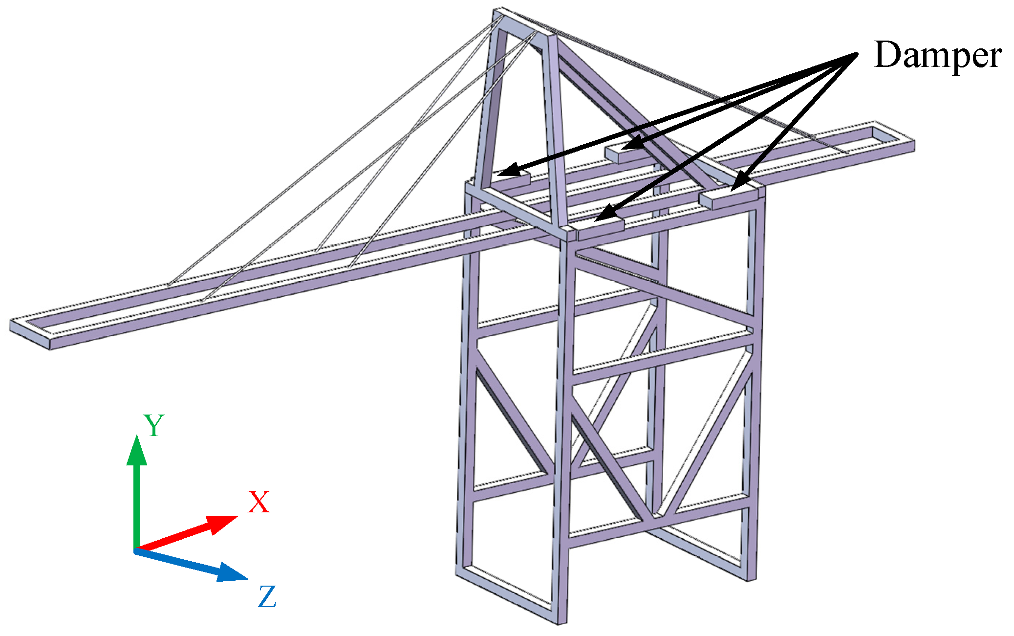
This study is only for the scenario when the transverse wind load acts on the crane, and the crane is under the anchoring state (rigid connection to the ground). Considering the mass distribution and the transportation space of the crane, the four dampers are installed on the shoulder, as shown in Figure 1.
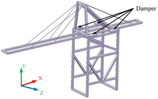
Figure 1.
Crane model (3D sketch of the experimental model).
3. Theoretical Analysis
3.1. Design of Simplified Model and Calculation of Stiffness Equation
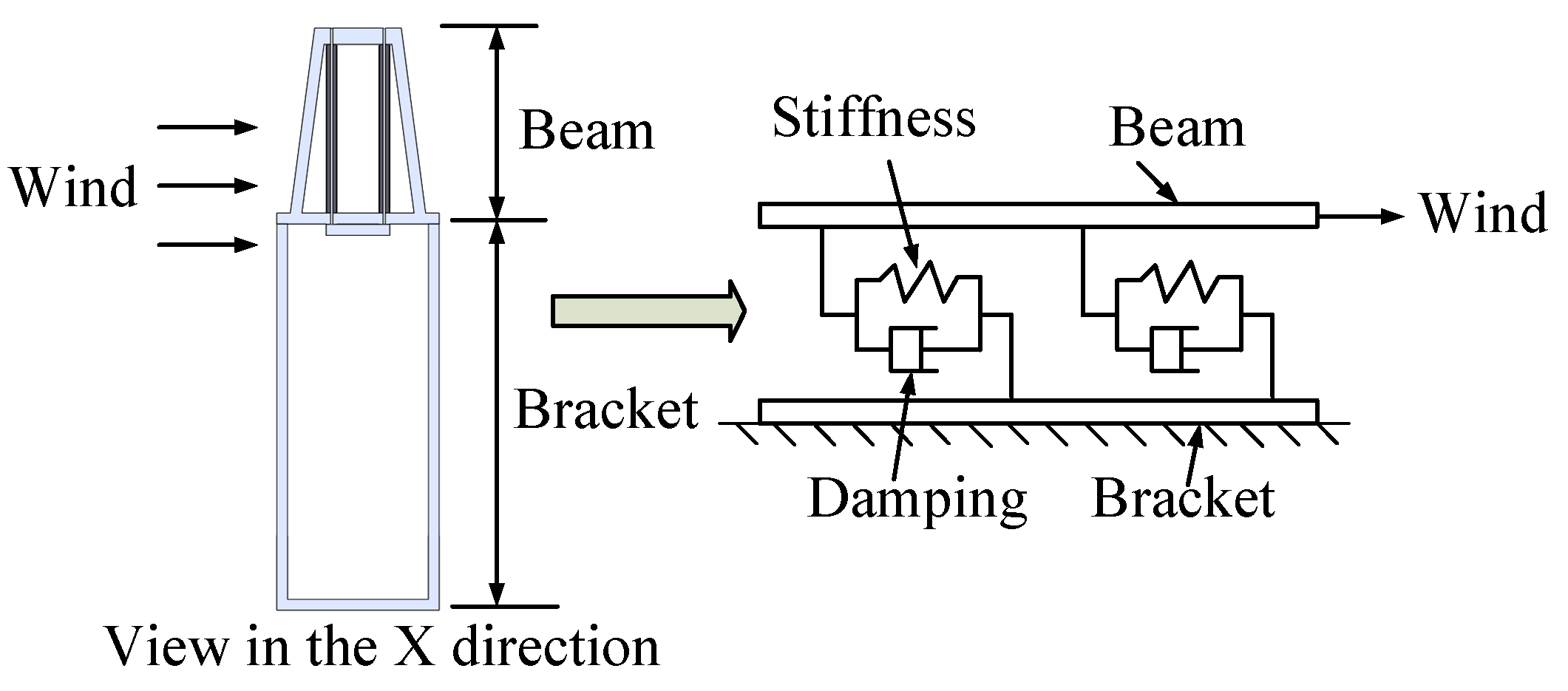
To investigate whether the installation of the particle damper has a vibration suppression effect on the crane in advance, it is necessary to establish the mathematical model of the crane with particle dampers installed and analyze it. Therefore, the actual crane system is simplified as a 1-DOF system, the macrostructure is divided into beam structure and bracket structure. The equivalent mechanical model is shown in Figure 2.
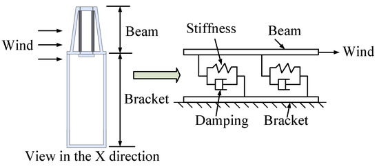
Figure 2.
Process of mechanical modeling.
The particle groups in the damper collide with each other and generate momentum exchange, which makes the dynamic response between the particles show strong nonlinear characteristics. Because of this feature, the numerical simulation of particle dampers becomes complicated, and it is always a difficult point in the field of particle dampers research. Therefore, at the initial stage of the research, it is necessary to formulate an appropriate equivalent simplification rule to carry out equivalent simplification of particle groups on the premise of retaining the key dynamic characteristics of particle dampers.
According to the results of large-scale shaking table tests conducted by some scholars, multiple particles move in the form of “plug flow”; that is, multiple particles move as a whole [18]. So, based on the following assumption, the multiple particles in the damper are equivalent and to a single particle:
- (1)
- The gap of the damper cavity before and after equivalent simplification is equal;
- (2)
- The total mass of multiple particles before equivalent simplification is equal to the mass of individual particles after equivalent simplification;
- (3)
- The particle damper before the equivalent simplification is a cuboid, the single particle damper after the equivalent simplification is a cylinder, and the diameter of the cylinder is equal to the diameter of the single particle after the equivalent simplification;
- (4)
- The contact between the particle and the cavity wall is also expressed in terms of stiffness and damping.
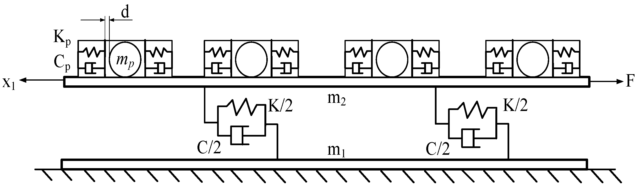
The 1-DOF equivalent mechanical model with dampers is established, as shown in Figure 3.
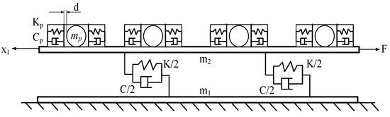
Figure 3.
The equivalent mechanical model with dampers.
where K is the equivalent stiffness of the steel frame, C is the equivalent damping of the steel frame, m1 is the mass of the bracket structure, m2 is the beam structural mass, mp is the mass of the sphere, Kp is the contact stiffness between the sphere and cavity wall, Cp is contact damping between sphere and cavity wall, d is the initial distance between the sphere and the cavity wall (it is symmetric concerning both sides of the cavity wall), F is wind load, x1 is the displacement of the beam structure.
Under the condition that the relative displacement between the sphere and the cavity is less than d, the collision behavior does not occur, and the elastic force and damping force are zero. Under the condition that the relative displacement between the sphere and the cavity is greater than d, collision behavior occurs, resulting in collision force. Therefore, the collision process between the sphere and the inner wall of the cavity is represented by stage linearization to simulate the relative displacement and velocity of the inelastic collision between the rigid wall and the sphere. The functions G and H represent the stage linear stiffness and stage linear damping characteristic of the particle damper.
where xp is the displacement of the sphere.
Under the action of wind load F, the beam structure represented by the mass block m2 is offset; that is, the displacement x1 is generated. In addition, the bottom of the crane is in an anchored state, so the mass block m1 does not move. Therefore, the stiffness equation is obtained according to the model:
where w is the damping force generated by a single particle damper.
3.2. Simulink Modeling and Solution
To verify the effect of vibration suppression, the stiffness equation is expressed in the form of a Simulink module and solved.
The calibration process of relevant parameters in the stiffness equation is shown as follows:
- (1)
- The weight of the crane model is obtained by weighing;
- (2)
- A certain tension is applied to the upper part of the model, and the upper part of the model is offset under the action of the tension. The stiffness of the bracket structure is calculated by the offset and the indicator of the tension device;
- (3)
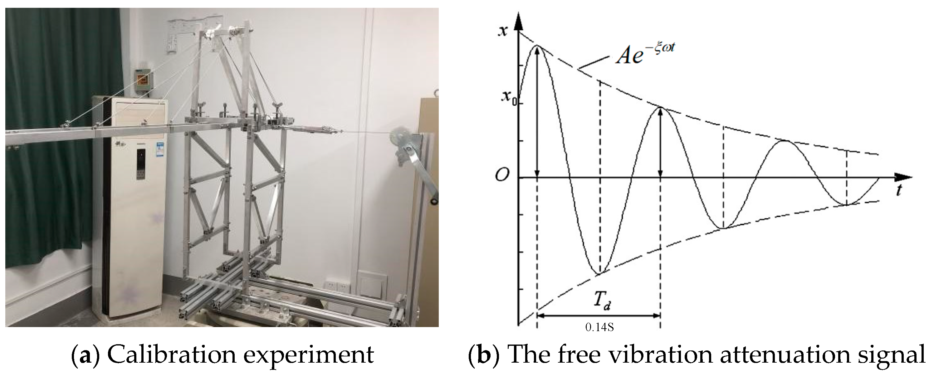
- The tension is released, the free vibration attenuation signal of the model is detected by the acceleration sensor, and the damping ratio of the model is identified by the envelope of the free vibration attenuation signal. The experiment layout is shown in Figure 4.
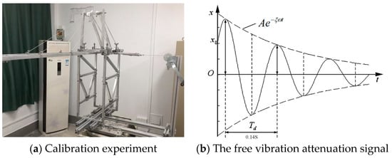 Figure 4. Experiment layout.
The acceleration attenuation response of the 1-DOF system with dampers can be expressed as
The corresponding envelope equation is
where A is the amplitude, ω is the natural frequency, Φ is the phase angle, ξ is the damping ratio.
The damping value is obtained from the following formula:
where M is the total mass of the model.
The equivalent spring stiffness and damping of the collision between the sphere and the cavity wall can be calculated by the angular frequency:
According to Masri’s and Ibrahim’s research [19], under the condition that the stiffness of the spring simulating collision is much larger than that of the main structure, the interaction between particles and the cavity wall can be more appropriately simulated. Therefore, 20 times the angular frequency of the main structure is taken as the angular frequency of the particle. The particle material is steel, so the damping ratio ξp is 0.375.
All of the parameters in the stiffness equation are shown in Table 2.
Table 2.
Table of parameters in the stiffness equation.
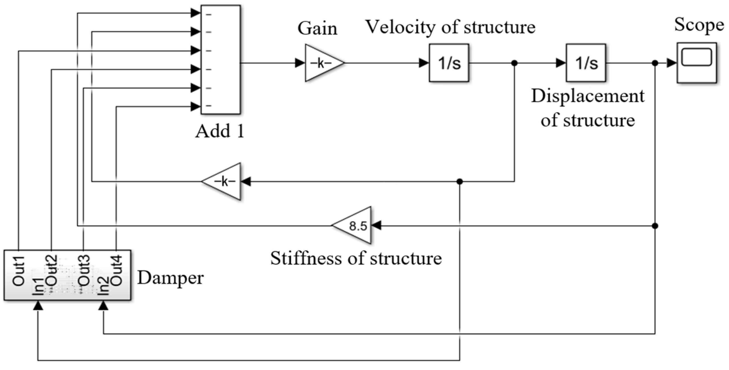
The external load is gradually applied to 10 N and returns to zero at some point. At this time, the main structure presents free damping vibration. The specific solving model is shown in Figure 5.
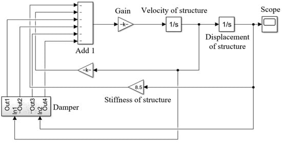
Figure 5.
Motion equation modeling of the main structure.
The solution results show that with the addition of particle dampers, the vibration amplitude of the beam structure decreases obviously, and the wave crest lags behind compared with that without particle dampers, as shown in Figure 6.
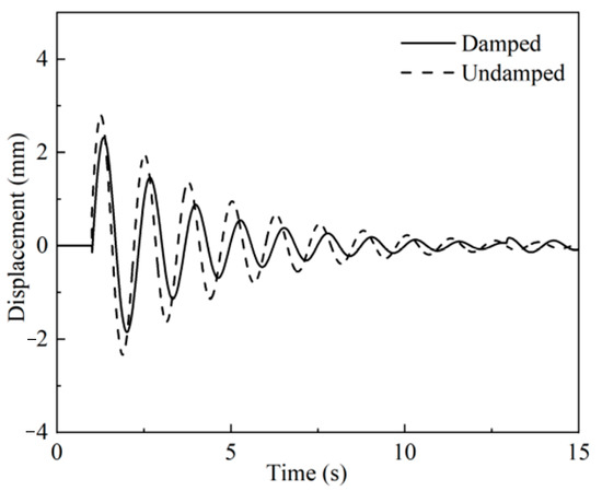
Figure 6.
Numerical simulation displacement of the main structure.
The vibration suppression effect is measured by displacement response peak root mean square:
where S is the effect of vibration suppression, A is the root mean square displacement of the crane with the damper installed, and B is the root mean square displacement of the crane without the damper installed.
It is calculated that the damping effect of the damper reaches 25%. The above numerical simulation method preliminary verifies the feasibility of particle damper applied in crane vibration reduction function. However, it is difficult for numerical models to quantitatively discuss the parameters related to the physical characteristics of particles. To obtain the vibration suppression effect of particle dampers on cranes more accurately and complement the shortcomings of the numerical model, the following experiment is designed for further investigation.
4. Experimental
4.1. Experimental Platform
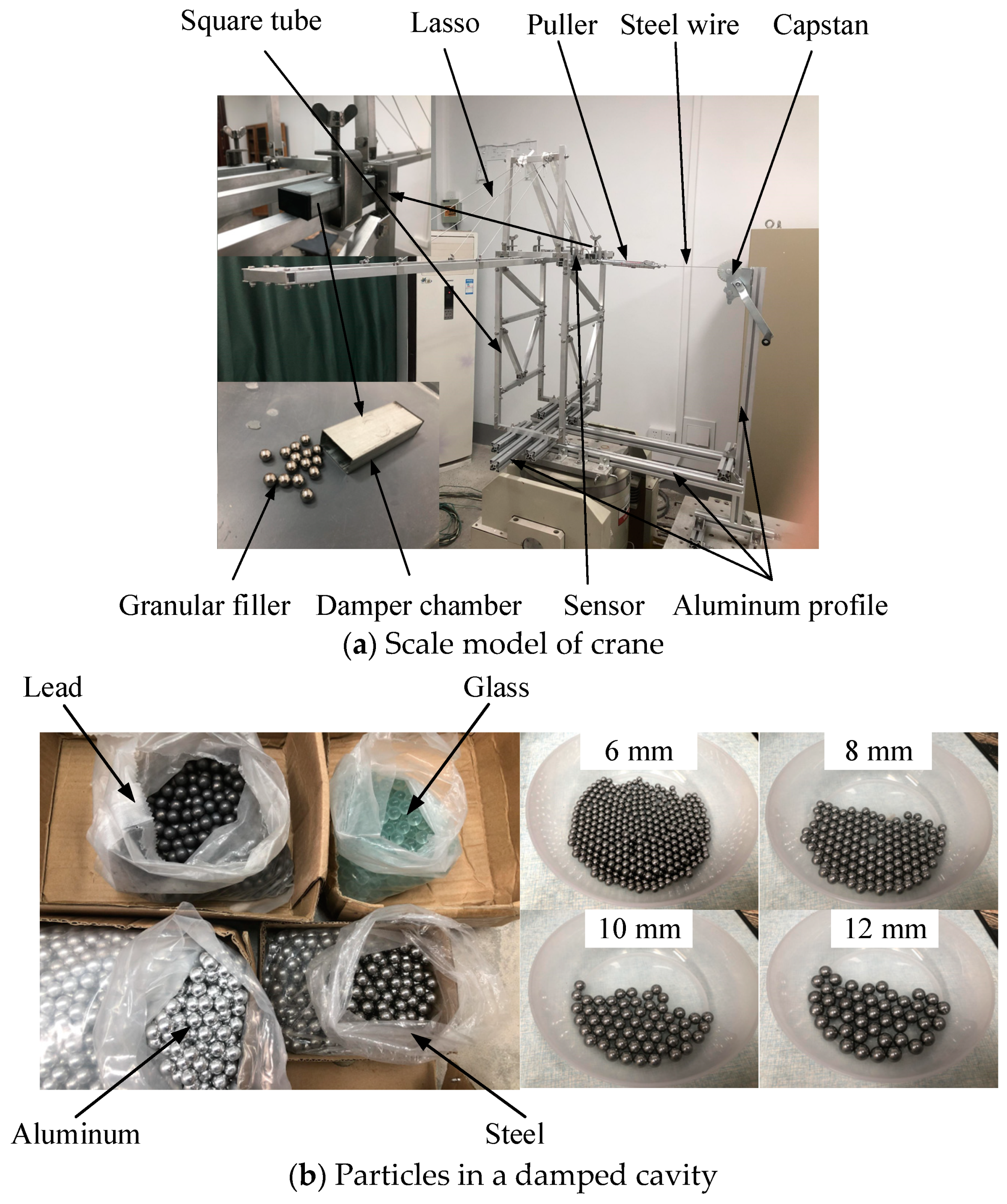
To further verify the vibration suppression effect and obtain optimal working parameters of the damper, vibration attenuation experiments are carried out. The experimental model uses square tube as raw material, the model is fixed with screws and nuts, the rope on the boom is replaced by steel wire rope, the base of the crane model uses 40 × 40 European standard aluminum profiles, and the damper is made of aluminum alloy square pipe. In this investigation, steel, aluminum, lead, and glass are used as the materials filled in the damper chamber. To facilitate the disassembly and installation of the particle damper, a 304 stainless steel butterfly opening vice is used to fix the particle damper. The arrangement of experimental equipment is shown in Figure 7.
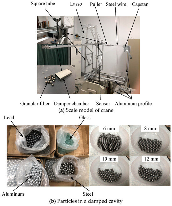
Figure 7.
Experimental equipment.
4.2. Description of Experiment Process
To simulate the residual vibration of the mechanism after experiencing wind load, a winch is used to pull the wire rope to offset the upper part of the experimental model, and the number shown by the indicator represents the initial wind load on the model. Then, after the model is stabilized and the number shown by the acceleration indicator is 0, the winch is released and the model generates residual vibration. Finally, the acceleration of the upper part of the experimental model is collected by the BWT61CL acceleration sensor, and the differences between the model accelerations when particle dampers are installed under different working parameters are compared.
Particle material, filling quantity, particle size, and position of the damper are taken as change parameters to conduct experiments and explore the law of vibration suppression effect changing with parameters. Specific parameters of experimental objects and conditions are shown in Table 3 and Table 4.
Table 3.
Parameter table of experimental material.
Table 4.
Parameter table of experimental conditions.
4.3. Effect of Different Materials on Vibration Suppression Characteristics
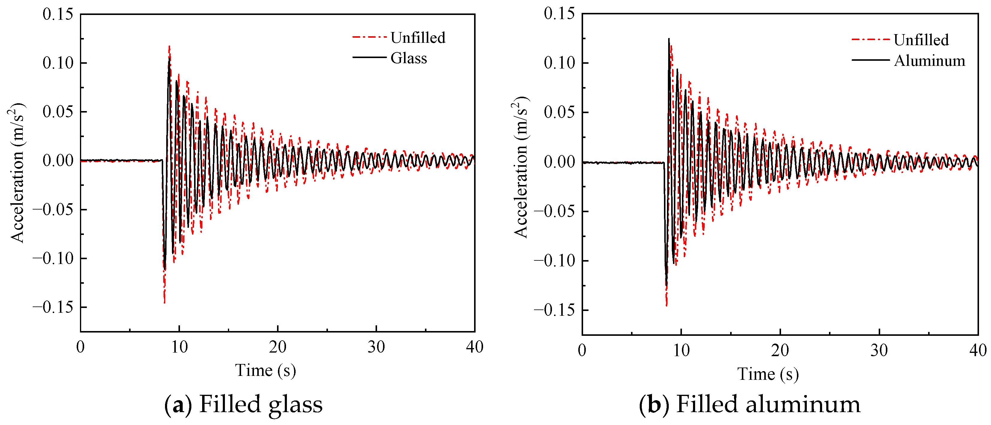
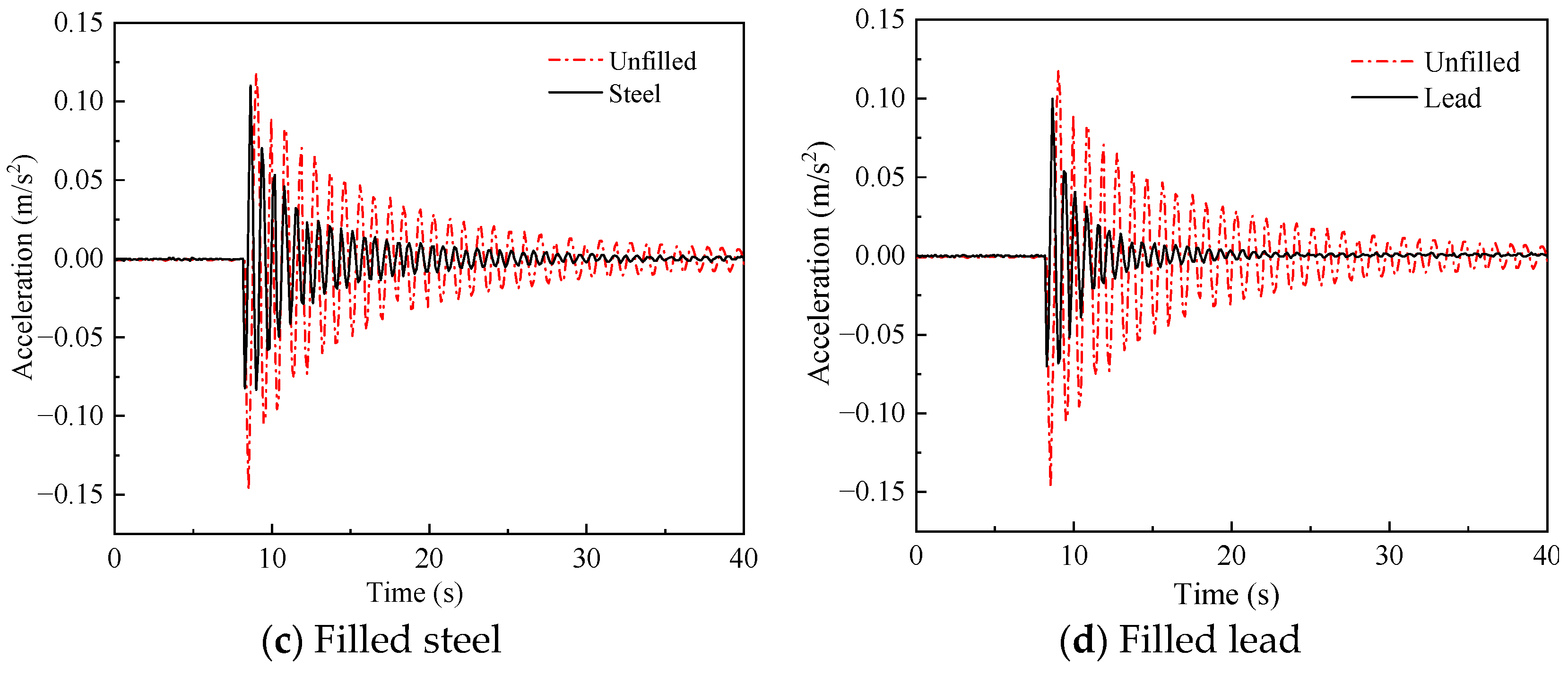
The energy dissipated by particle collision behavior in the damper determines the performance of the particle damper, and the difference in mechanical properties of different particle materials greatly affects their collision behavior. To investigate the effect of different materials on the performance of the damper, an experiment is conducted under the following conditions: the material of 10 mm particle groups is lead, steel, aluminum, and glass, the quantity of each particle group is 25, the external load is 10 N, and the installation position of the dampers is the proximal end. The experimental results are shown in Figure 8 and Figure 9.
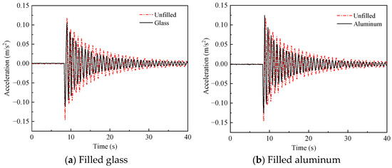
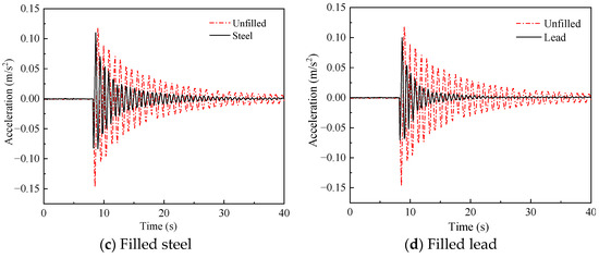
Figure 8.
Comparison of vibration acceleration of structure under different filling materials of damper.

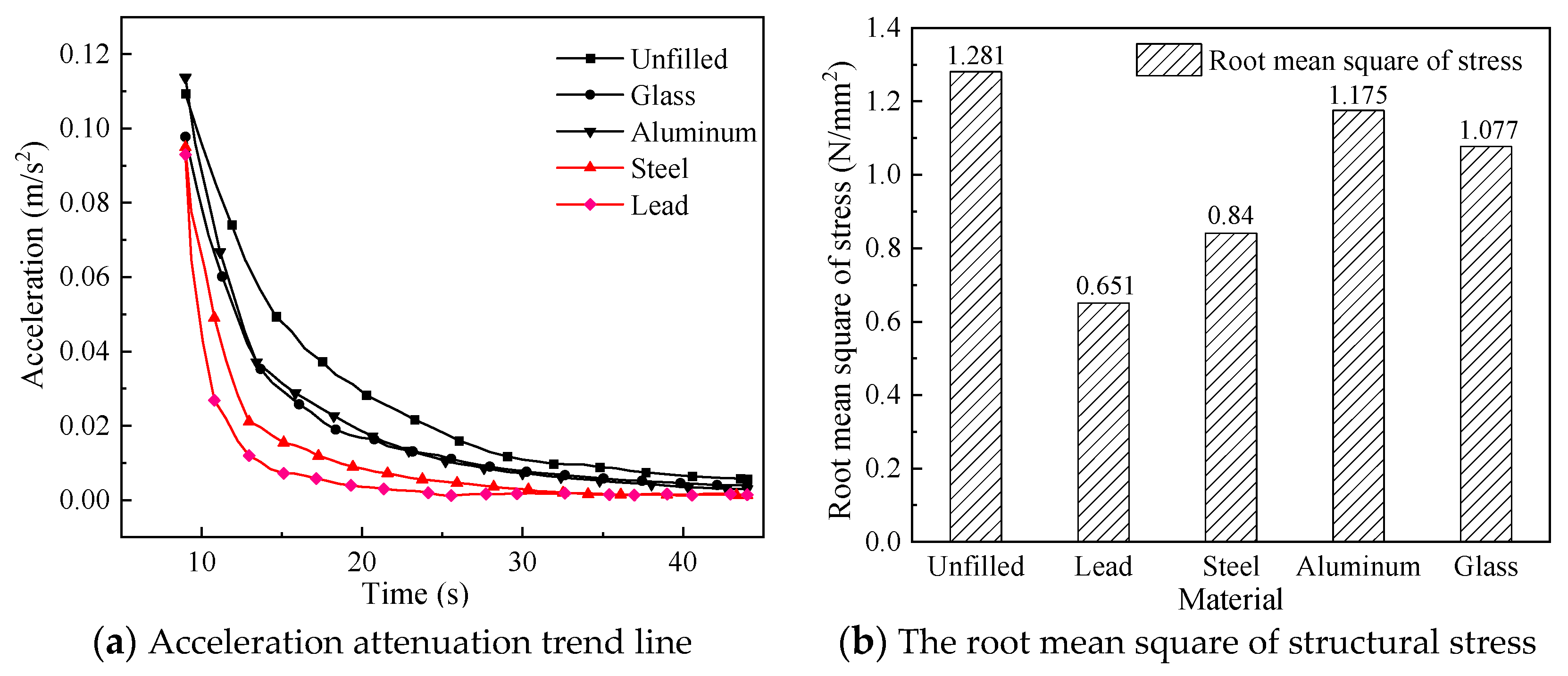
Figure 9.
Acceleration attenuation trend line and the root mean square of structural stress of structure.
From Figure 8, whatever the filling material in the damper, the installation of the particle damper reduces the crest area of the acceleration and affects the vibration suppression of the crane. Figure 9 shows that the acceleration of the model tends to steady state after the shortest time (18 s) and the root mean square reaches 0.651 with the filling material of particle damper being lead beads. The time for the acceleration to reach the steady state becomes longer successively with the filling materials in the damper are steel, glass, and aluminum, which is 27 s, 30 s, and 32 s, respectively. In addition, the root mean square of stress increases successively, which is 0.84, 1.077, and 1.175, respectively. Therefore, the damping effect is the best with the material inside the damper being lead, because higher the density and elastic modulus of the material, the better the impact resistance performance.
4.4. Effect of Different Filling Rates on Vibration Suppression Characteristics
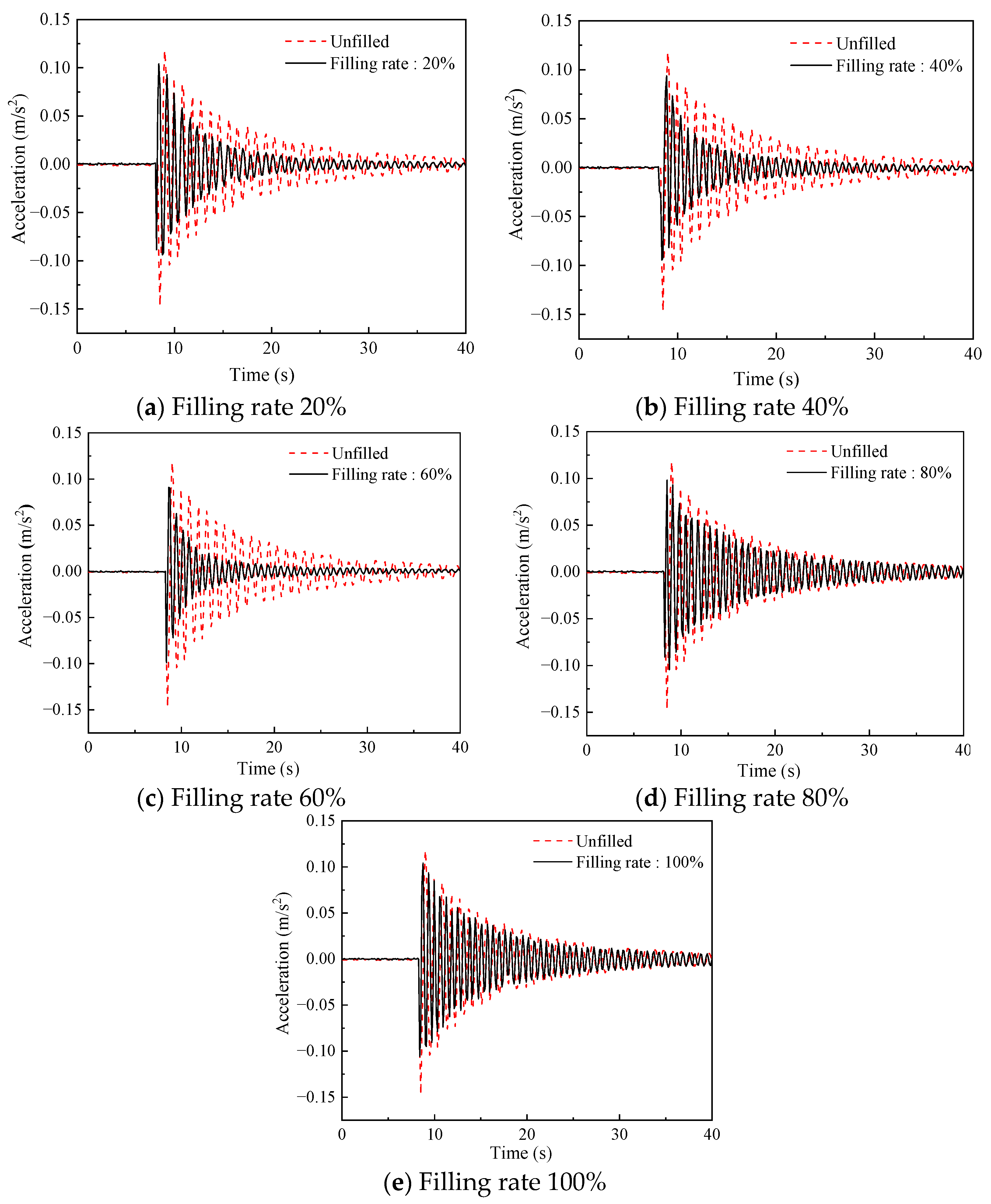
With the increase of the quantity of the particles in the damper, the anti-impact ability of the damper increases correspondingly. However, the impact efficiency is also affected by the quantity of the particles. To investigate the optimal filling rate of the damper, the experiment is conducted under the following conditions: external load 10 N, the installation position of the dampers is the proximal end, the quantity of 10 mm steel ball groups is 10 (filling rate of 20%), 20 (filling rate of 40%), 30 (filling rate of 60%), 40 (filling rate of 80%), and 50 (filling rate of 100%). The experimental results are shown in Figure 10 and Figure 11.
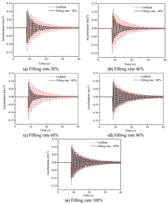
Figure 10.
Comparison of vibration acceleration of structure under different filling rates of damper.
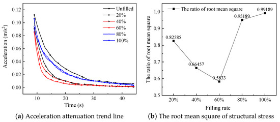
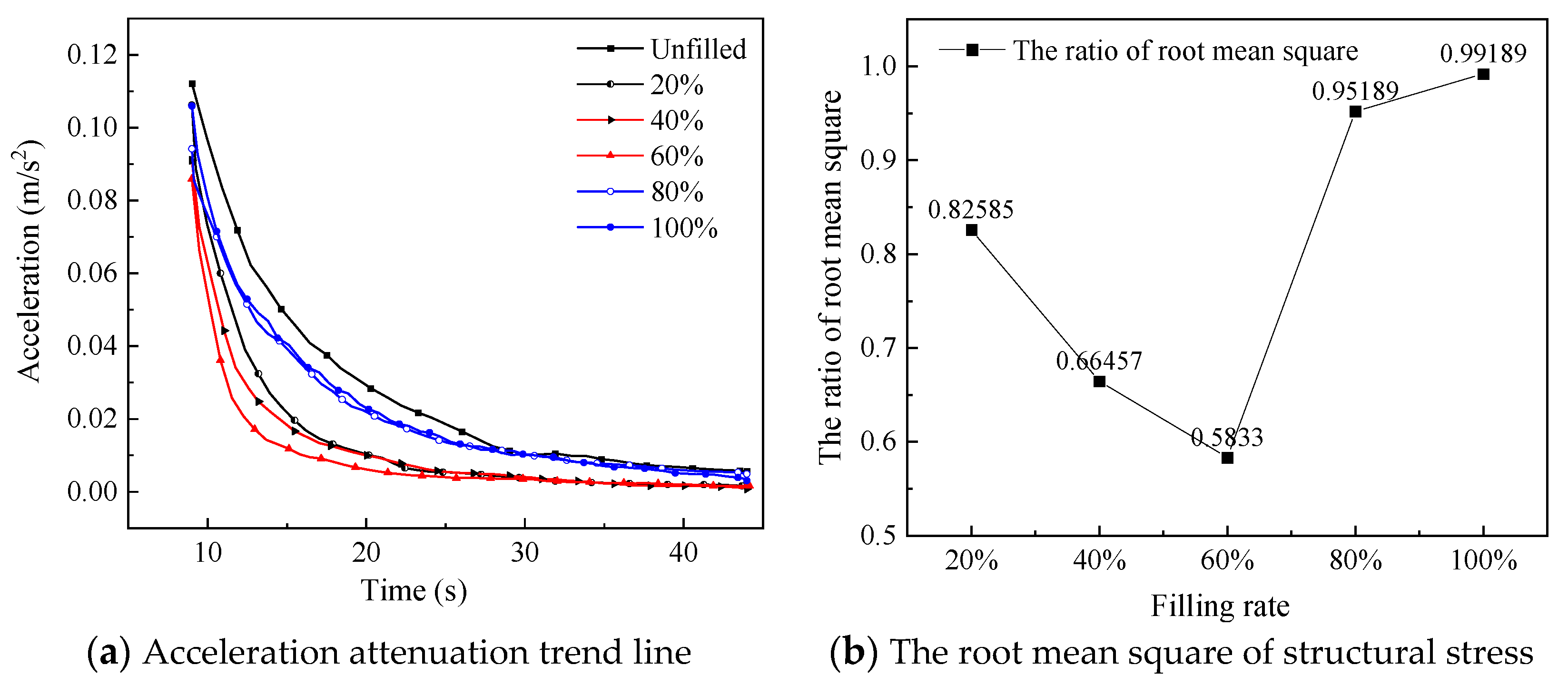
Figure 11.
Comparison of acceleration attenuation trend line and the root mean square of structural stress of structure under different filling rates.
As shown in Figure 10, regardless of the filling rate in the damper, the installation of the particle damper has a certain effect on the vibration suppression of the crane (except for the case of the filling rate of 0). From Figure 11, the increase in filling rate from around 20% to 60% reduces the time for the acceleration to reach a steady state and decreases the root mean square. However, as the filling rate continues to increase, it can be seen that the root mean square increases sharply, and the vibration suppression effect of the crane model decreases. Therefore, when the filling rate of the damper is 60%, the crane can obtain the best vibration suppression effect. This is because, under the premise that the number of particles in the damper can bring enough impact strength to the damper, enough space is left for the particles to carry out sufficient collision, which can make the damper obtain the best vibration suppression performance.
4.5. Effect of Different Particle Diameters on Vibration Suppression Characteristics
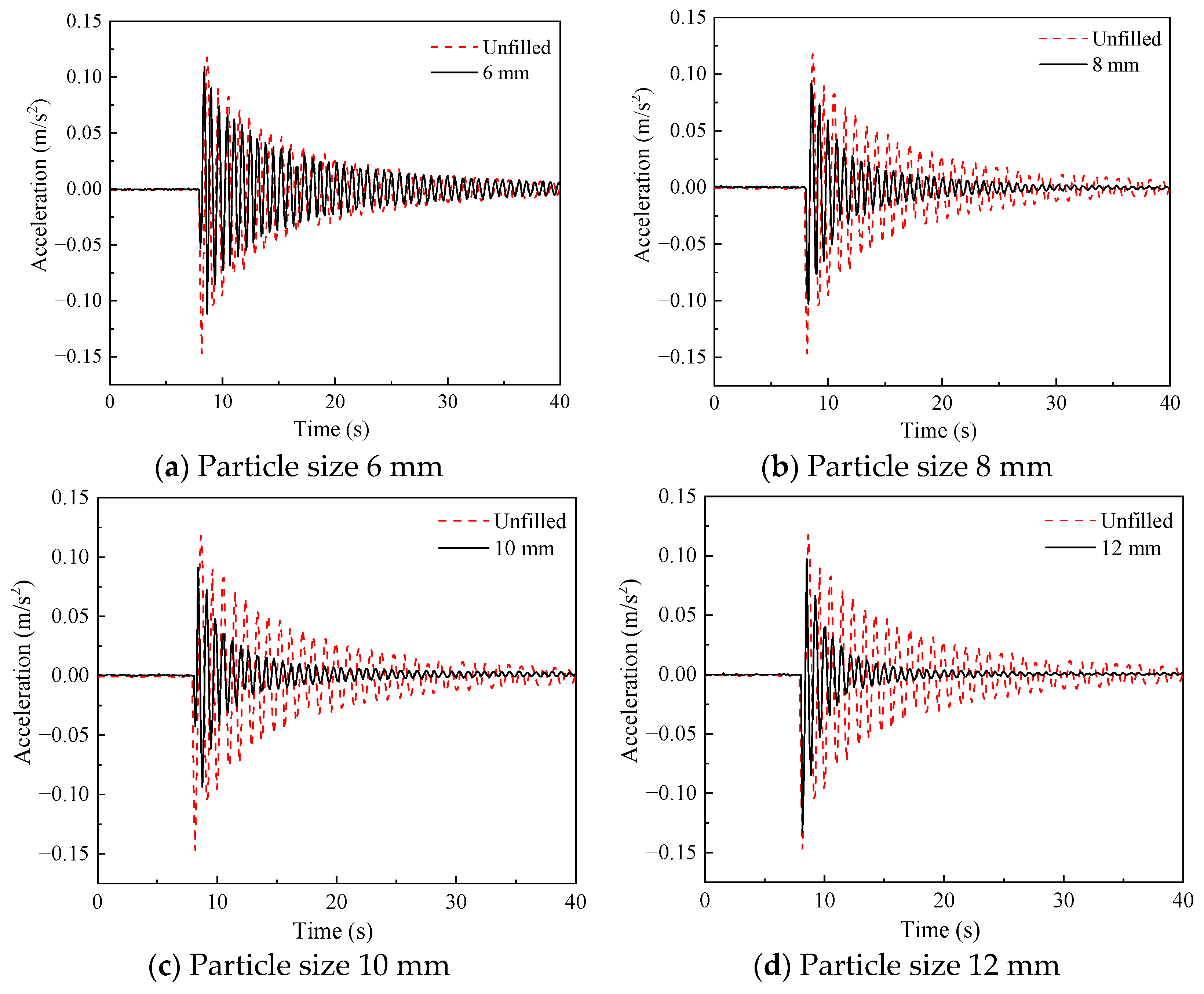
Particle size is a key factor that affects the movement of particles in a closed cavity. On the premise that the filling mass in the damper is equal, the contact efficiency between the particles will increase with the decrease of the particle size. To investigate the effect of particle size on the vibration suppression performance of particle damper, an experiment is conducted under the following conditions: particle group with diameters of 6 mm, 8 mm, 10 mm, and 12 mm, total weight of each particle group is 127 g, the external load is set at 10 N, and the installation position of the dampers is proximal end. The experimental results are shown in Figure 12 and Figure 13.
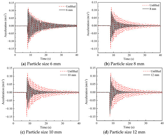
Figure 12.
Comparison of vibration acceleration of structure under different filling particle sizes of dampers.
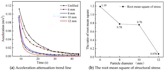
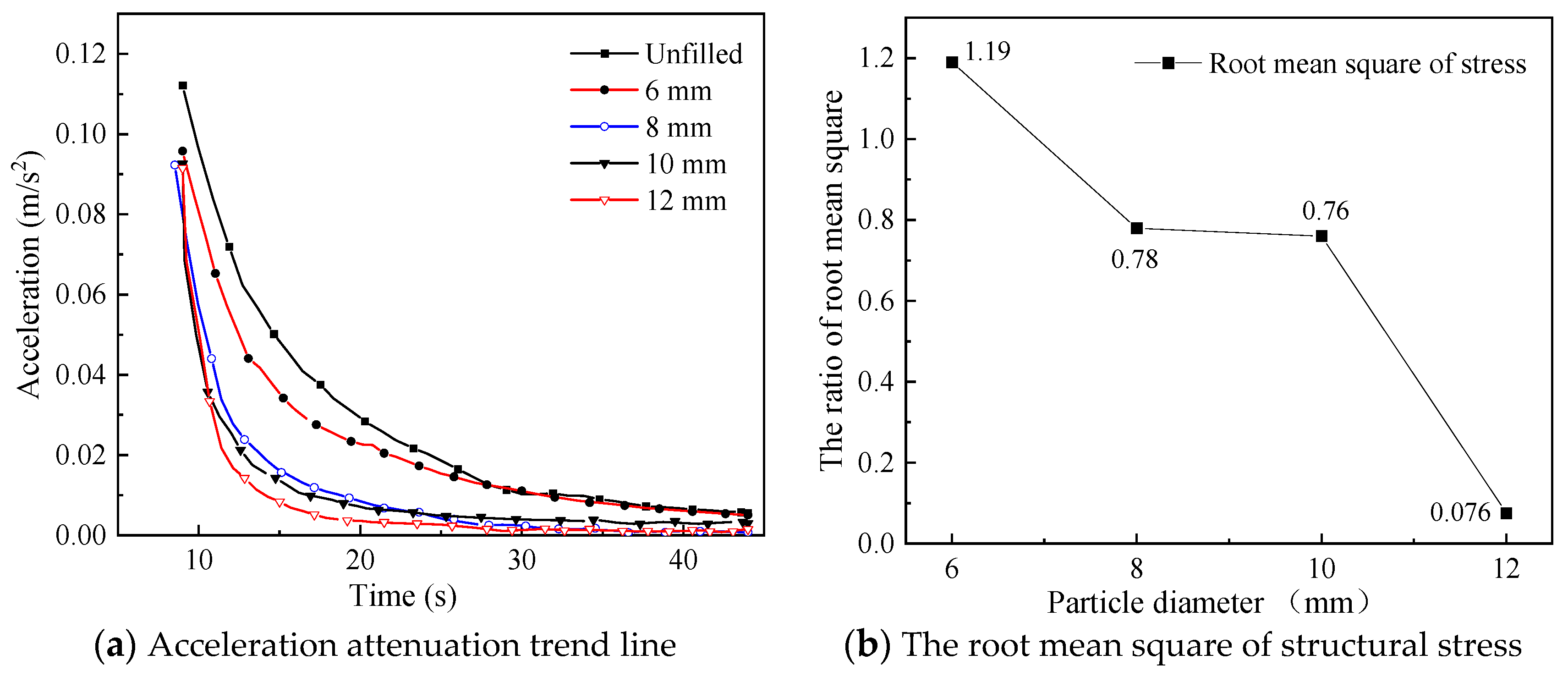
Figure 13.
Comparison of acceleration attenuation trend line and the root mean square of structural stress of structure under different particle sizes.
Figure 12 shows that regardless of the diameter of the particles packed in the damper, the installation of the particle damper reduces the crest area of the acceleration and has an effect on the vibration suppression of the crane. From Figure 13, the increase in diameter of the particles from around 6 mm to 12 mm reduces the time for the acceleration to reach a steady state and decreases the root mean square. Obviously, compared to several other smaller diameters, the diameter of the particles packed in the damper is 12 mm allowing for the best effect in the vibration suppression of the crane. This is due to the fact that with the increase of particle diameter, the mobility presented by particle group motion decreases, and the dispersion of particle group increases, resulting in the increase of collision frequency, and the ability of the damper to convert external kinetic energy into heat energy and thus dissipate increases.
4.6. Effect of the Installation Position of the Damper on Vibration Suppression Characteristics
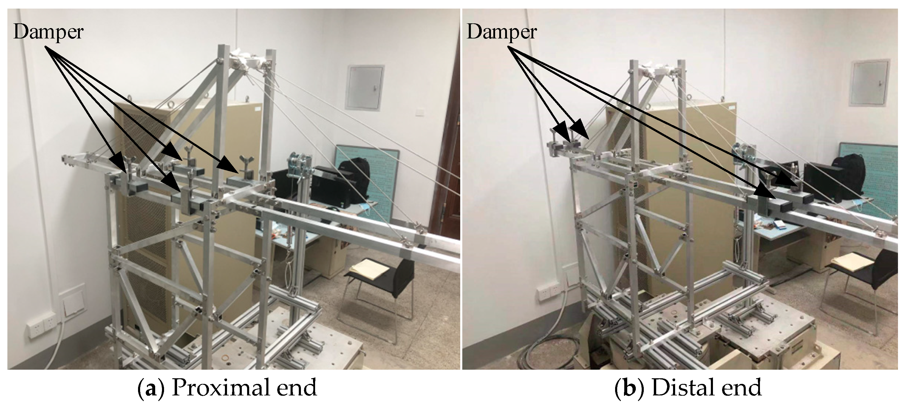
Most container cranes have a high center of gravity and a long extension distance, causing torsional torque to the bottom structure. To investigate the influence of the installation position of the damper on the vibration suppression effect, the experiments are conducted under the following conditions: the external load of 10 N, the filling rate of 10 mm steel ball groups is 50%, and the installation position of the dampers is the proximal end and the distal end. Figure 14 shows the two installation methods, and the experimental results are shown in Figure 15.

Figure 14.
Installation mode of the damper.

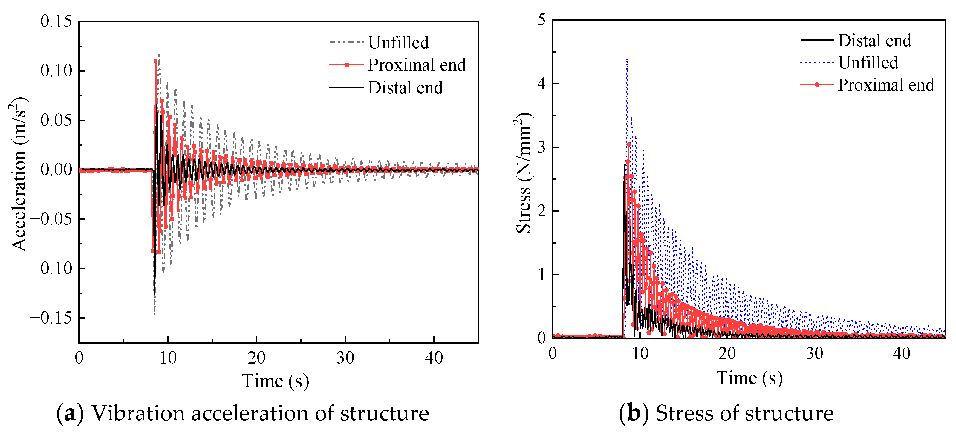
Figure 15.
Vibration acceleration and stress of structure.
It can be seen from Figure 15 that the installation of the damper at the proximal or distal end reduces the crest area of the structure acceleration and decreases the value of stress. Furthermore, the vibration suppression effect is better under the condition that the dampers are installed at the distal end. However, in order to reduce the bending moment of the crane arm and avoid overturning in practical engineering applications, it is necessary to avoid installing the dampers on the crane forearm. Therefore, the damper is installed at the distal end as far as possible under the condition that the strength of the crane forearm allows.
5. Conclusions
From the results and discussion above, the following can be
The vibration suppression effect of the damper is preliminarily verified by the Simulink module, and it is concluded that the vibration amplitude of the beam structure decreases obviously, the wave crest of displacement lags with the dampers are installed, and the damping effect reaches 25% by calculation.
The vibration suppression experiments are analyzed with several groups of different conditions, it is concluded that the installation of a particle damper decreases the acceleration crest area of the structure and reduces the time for the acceleration to reach a steady state.
This vibration suppression method is firmed effective, with the filling parameter of the dampers being 12 mm lead bead, and the filling rate is 60% when the dampers are installed on the distal end of the crane.
Author Contributions
Resources, F.Y.; Writing—Original Draft, X.X.; Investigation, W.J.; Funding Acquisition, X.Y. All authors have read and agreed to the published version of the manuscript.
Funding
This study was funded by the Major Science and Technology Project of Hubei Province Grants No. 2021AAA007, the Natural Science Foundation of Hubei Province Grants No. 2023AFB400, and the Hubei University of Technology Research Fund under Grants BSQD2020009.
Data Availability Statement
Data are contained within the article.
Conflicts of Interest
The authors declare no conflicts of interest.
References
- Hebiba, A.M.; Bouferguene, A.; Moon, S. Automated Stability Analysis for Selection of Tower Crane and Location. J. Constr. Eng. Manag. 2022, 148, 04022127. [Google Scholar] [CrossRef]
- Zhang, W.; Xue, N.N.; Zhang, J.R. Identification of Critical Causal Factors and Paths of Tower-Crane Accidents in China through System Thinking and Complex Networks. J. Constr. Eng. Manag. 2021, 147, 04021174. [Google Scholar] [CrossRef]
- Tran, Q.H.; Huh, J.; Doan, N.S. Fragility Assessment of a Container Crane under Seismic Excitation Considering Uplift and Derailment Behavior. Appl. Sci. 2019, 9, 4660. [Google Scholar] [CrossRef]
- Xing, X.Y.; Liu, J.K. State-estimator-based robust vibration control of crane bridge system with trolley via PDE model. Commun. Nonlinear Sci. 2021, 99, 105799. [Google Scholar] [CrossRef]
- Al-Fadhli, A.; Khorshid, E. Payload oscillation control of tower crane using smooth command input. J. Vib. Control 2021, 29, 902–915. [Google Scholar] [CrossRef]
- Zhao, X.S.; Huang, J. Distributed-mass payload dynamics and control of dual cranes undergoing planar motions. Mech. Syst. Signal Pr. 2019, 126, 636–648. [Google Scholar] [CrossRef]
- Meyer, N.; Seifried, R. Damping prediction of particle dampers for structures under forced vibration using effective fields. Granul. Matter. 2021, 23, 64. [Google Scholar] [CrossRef]
- Rakhio, A.; Ido, Y.; Iwamoto, Y. Experimental and Numerical Analysis of Torque Properties of Rotary Elastomer Particle Damper considering the Effect of Gap and No Gap between Rotor and Body of the Damper. Shock. Vib. 2022, 2021, 7724156. [Google Scholar] [CrossRef]
- He, H.X.; Wang, B.S.; Yan, W.M. Mechanical Model and Optimization Analysis of Multiple Unidirectional Single-Particle Damper. J. Eng. Mech. 2021, 147, 04021040. [Google Scholar] [CrossRef]
- Lu, Z.; Wang, Z.X.; Masri, S.M. Particle impact dampers: Past, present, and future. Struct. Control Health Monit. 2018, 25, 2058. [Google Scholar] [CrossRef]
- Yan, W.M.; Xu, W.B.; Wang, J. Experimental research on the effects of a tuned particle damper on a viaduct system under seismic loads. J. Bridge Eng. 2014, 19, 04013004. [Google Scholar] [CrossRef]
- Chockalingam, S.; Natarajan, U.; Cyril, A.G. Damping investigation in boring bar using hybrid copper-zinc particles. J. Vib. Control 2017, 23, 2128–2134. [Google Scholar] [CrossRef]
- Hassui, A.; Suyama, D.I.; Magri, A. Reduction of internal turning surface roughness by using particle damping aided by airflow. Int. J. Adv. Manuf. Technol. 2019, 106, 125–131. [Google Scholar]
- Meyer, N.; Schwartz, C.; Morlock, M. Systematic design of particle dampers for horizontal vibrations with application to a lightweight manipulator. J. Sound. Vib. 2021, 510, 116319. [Google Scholar] [CrossRef]
- Wang, J.; Juan, M.X.; Yang, S.G. Experimental Investigation of the Vibration Reduction of the Pipeline System with a Particle Impact Damper under Random Excitation. Appl. Sci. 2023, 13, 618. [Google Scholar] [CrossRef]
- Papaluo, A.; Strepelias, E.; Roubien, D. Seismic protection of monuments using particle dampers in multi-drum columns. Soil. Dyn. Earthq. Eng. 2015, 77, 360–368. [Google Scholar] [CrossRef]
- Li, Z.; Ye, F.P.; Wu, S.Y. Design and Experimental Verification of a 1/20 Scale Model of Quayside Container Crane Using Distortion Theory. Shock. Vib. 2019, 2019, 5893948. [Google Scholar] [CrossRef]
- Lu, Z.; Liao, Y.; Huang, Z.K. Stochastic response control of particle dampers under random seismic excitation. J. Sound. Vib. 2020, 481, 115439. [Google Scholar] [CrossRef]
- Masri, S.F.; Ibrahim, A.M. Response of the Impact Damper to Stationary Random Excitation. J. Acoust. Soc. Am. 1973, 53, 200–211. [Google Scholar] [CrossRef]

Disclaimer/Publisher’s Note: The statements, opinions and data contained in all publications are solely those of the individual author(s) and contributor(s) and not of MDPI and/or the editor(s). MDPI and/or the editor(s) disclaim responsibility for any injury to people or property resulting from any ideas, methods, instructions or products referred to in the content. |
© 2023 by the authors. Licensee MDPI, Basel, Switzerland. This article is an open access article distributed under the terms and conditions of the Creative Commons Attribution (CC BY) license (https://creativecommons.org/licenses/by/4.0/).