
Thrust Model and Trajectory Design of an Interplanetary CubeSat with a Hybrid Propulsion System

Department of Civil and Industrial Engineering, University of Pisa, I-56122 Pisa, Italy
Actuators 2024, 13(10), 384; https://doi.org/10.3390/act13100384
Submission received: 29 August 2024
/
Revised: 24 September 2024
/
Accepted: 25 September 2024
/
Published: 1 October 2024
(This article belongs to the Special Issue Dynamics and Control of Aerospace Systems)
Abstract
:This paper analyzes the performance of an interplanetary CubeSat equipped with a hybrid propulsion system (HPS), which combines two different types of thrusters in the same deep space vehicle, in a heliocentric transfer between two assigned (Keplerian) orbits. More precisely, the propulsion system of the CubeSat considered in this work consists of a combination of a (low-performance) photonic solar sail and a more conventional solar electric thruster. In particular, the characteristics of the solar electric thruster are modeled using a recent mathematical approach that describes the performance of the miniaturized engine that will be installed on board the proposed ESA’s M-ARGO CubeSat. The latter will hopefully be the first interplanetary CubeSat to complete a heliocentric transfer towards a near-Earth asteroid using its own propulsion system. In order to simplify the design of the CubeSat attitude control subsystem, we assume that the orientation of the photonic solar sail is kept Sun-facing, i.e., the sail reference plane is perpendicular to the Sun-CubeSat line. That specific condition can be obtained, passively, by using an appropriate design of the shape of the sail reflective surface. The performance of an HPS-based CubeSat is analyzed by optimizing the transfer trajectory in a three-dimensional heliocentric transfer between two closed orbits of given characteristics. In particular, the CubeSat transfer towards the near-Earth asteroid 99942 Apophis is studied in detail.
1. Introduction
The trajectory analysis and the transfer performance of an interplanetary spacecraft are closely related to the specific characteristics of the propulsion system installed on board [1,2,3]. This crucial aspect of spacecraft design is particularly important when considering a small spacecraft, such as a CubeSat, whose recent use in interplanetary applications is revealing its high potential [4,5,6,7] thanks to successful missions such as the pioneering NASA’s Mars Cube One (MarCO) [8,9] and the more recent Light Italian CubeSat for Imaging of Asteroids (LICIACube) of the Italian Space Agency (ASI) [10]. In the context of the design of a small-spacecraft-based interplanetary mission [11,12,13], the choice of the type of propulsion system is usually a compromise between conflicting requirements [14,15] such as, for example, the weight limitation (or the volume reserved to the thruster subsystem), and the possibility of having a continuous, steerable thrust vector of sufficiently high magnitude.
From the viewpoint of the trajectory design, in fact, a continuous propulsive acceleration vector can be used for a long period of time in order to cover complex interplanetary orbits, or to complete deep space missions that require a high (or very-high) velocity change [16] without an excessive propellant expenditure when the propellant mass flow rate is low enough. A steerable thrust vector with a magnitude that can be varied within a prescribed (and sufficiently wide) range can be achieved by the use of a typical electric thruster, the use of which in small spacecraft has recently become a viable option [14,15,17] due to technological advances in the miniaturization of space vehicle components and subsystems, as detailed in Refs. [18,19,20,21]. However, the use of an electric thruster within a trajectory design process introduces the usual constraint due to the finite amount of propellant mass that can be stored on board of the interplanetary (small) spacecraft.
This last constraint can be overcome by considering a more advanced (and in some ways more exotic) propulsion system, such as the Electric Solar Wind Sail (E-sail) proposed by Dr. Pekka Janhunen [22,23], which deflects the charged particles of the solar wind using an artificial electric field generated by a series of long conducting tethers [24,25], or a more well-known photonic solar sail, which is a propellantless thruster that converts solar radiation pressure into thrust using a large (usually highly reflective) membrane with a metalized film coating [26,27]. Currently, starting from the successful Japanese mission Interplanetary Kite-craft Accelerated by Radiation Of the Sun (IKAROS) in 2010 [28,29], which first tested the concept of a solar sail-based propulsion system in interplanetary space, among the different propellantless thrusters proposed in the literature only the solar sail concept seems to have the technological maturity to be effectively employed in interplanetary robotic missions whose launch can be planned in the near future. Very hopefully, the upcoming flight tests of a scaled-down version of the E-sail in a Moon-centered high-elliptic orbit [30,31,32], will bring this fascinating propulsion system into the list of those actually usable in scientific missions to interplanetary space.
The use of a solar sail as the primary propulsion system, however, poses some additional constraints that must be carefully considered during the spacecraft trajectory design. In fact, the propulsive capabilities of a photonic solar sail are limited by the intrinsic impossibility of pointing the thrust vector towards the Sun and by the potential difficulty of continuously varying the attitude of a large space structure in order to follow a given guidance law [33]. Furthermore, taking into account the current technological level in solar sail design [34], the maximum magnitude of the propulsive acceleration vector given by that propellantless propulsion system is typically small when compared to the (local) Sun’s gravitational acceleration.
In this context, a possible solution is to employ a hybrid propulsion system (HPS) that combines, in the same spacecraft, two different types of space thrusters using different propellants or, more generally, different “thrust sources” in the case where propellantless propulsion systems are considered. The HPS concept is different from the more recent multimode propulsion system [35], which uses two different types of spacecraft engines that, however, share the same propellant type. In this case, the interesting review by Rovey et al. [36] represents an excellent starting point to recover the bibliography and technical information on this useful concept of (multimode) propulsion system. Assuming an HPS-propelled small spacecraft, this paper analyzes the transfer performance of an interplanetary CubeSat equipped with a combination of a (low-performance) photonic solar sail and a miniaturized electric thruster. The combined use of a solar sail and an electric thruster is not a new idea in the context of the heliocentric trajectory design, since such an interesting proposal (more precisely, the use of a solar sail and a nuclear electric propulsion system) was advanced by Dr. Giovanni Vulpetti over fifty years ago in one of his many pioneering articles on the use of photonic solar sail [37]. More precisely, Ref. [37] discussed the potential of a deep space probe equipped with an HPS to reach (and explore) the outer regions of the Solar System. The same idea of using a solar sail and an electric thruster was then taken up several times in the scientific literature [38,39], also by the author from the trajectory optimization point of view [40,41,42]. In this context, the interested reader can appreciate the elegant approach proposed by Ceriotti and McInnes [43] for the use of an HPS-equipped spacecraft for the generation of non-Keplerian orbits that can be used to observe the medium-high latitude areas of the Earth’s surface. In particular, the latter mission application is a sort of evolution of the concept of the “pole sitter” [44,45] proposed by Dr. Gregory Matloff [46] about twenty years ago.
In this paper, the propulsive characteristics of the HPS are described with the sole purpose of obtaining a simple mathematical model that can be used to simulate (and optimize by defining a suitable performance index) the CubeSat transfer trajectory in a typical heliocentric mission scenario. In other words, the design of the spacecraft from the point of view of its subsystems and the integration of the HPS within the space vehicle structure are not part of the scope of this work and, for this reason, will not be covered in this paper. Consequently, the presence of an HPS installed on board the interplanetary CubeSat will be schematized by describing the part of the total propulsive acceleration due to the miniaturized solar electric thruster and the part related to the presence of the photonic solar sail. Note that the presence of a complex system such as the HPS would require, in reality, the careful choice of the spacecraft attitude variation law during interplanetary flight, in order to avoid the propellant expelled by the solar electric thruster hitting the solar sail, thus degrading [47,48] the reflective characteristics of the film that covers the sail membrane. In order to simplify the design of the small spacecraft attitude control subsystem, we assume that the orientation of the (low-performance) photonic solar sail is kept Sun-facing, i.e., the sail nominal plane is perpendicular to the Sun-CubeSat line. That specific condition is obtained, passively, by using an appropriate design of the shape of the reflective surface. Indeed, as McInnes [49] pointed out, a Sun-facing attitude is obtained passively using a slightly conical (or, in general, an axially symmetric [50]) sail shape with the apex pointing towards the Sun.
The propulsive characteristics of the HPS considered in this work are obtained by analyzing the literature data regarding two interplanetary CubeSats equipped with a solar electric thruster or a photonic solar sail [51]. In particular, the characteristics of the miniaturized solar electric thruster are modeled using a recent mathematical description proposed by the author [52], which schematize the performance of the space engine that will be installed on board the proposed ESA’s CubeSat M-ARGO (which is the acronym for The Miniaturised Asteroid Remote Geophysical Observer); see the artistic concept in Figure A1. In fact, M-ARGO will hopefully be the first interplanetary CubeSat to complete a heliocentric orbit transfer using the solar electric thruster (in this specific case, a single radiofrequency gridded ion thruster) installed on board [53,54]. In particular, the M-ARGO’s planned heliocentric orbital transfer will start from the second collinear Lagrangian point of the Sun-Earth system, where the (piggyback) CubeSat will be parked by the launch system and will allow the small spacecraft to complete a rendezvous with a near-Earth asteroid. The asteroid to be reached has yet to be selected from a set of possible targets [55].
More precisely, the mathematical model of the solar electric propulsion system used in this paper coincides with the one described in Ref. [52], which is in turn a simplified version of the surrogate, and elegant, model proposed by Topputo et al. [54] a few years ago for the preliminary trajectory design of M-ARGO. This simplified thrust model is summarized in Appendix A, while the interested reader can find all the useful details of the mathematical model and some interesting mission applications in the two related references [52,54]. On the other hand, the propulsive characteristics of the solar sail were chosen using data available in the literature regarding NASA’s mission Near-Earth Asteroid Scout (NEA Scout) [56,57,58], an artistic representation of which is shown in Figure A3. In fact, NEA Scout was one of the ten CubeSat deployed during the maiden flight of the Space Launch System in November 2022, and that interplanetary mission was designed to approach asteroid 2020 GE and to take some pictures of this very small celestial body which approaches the orbit of Earth. Unfortunately, the ground station was unable to establish contact with the solar sail-based CubeSat, so the NEA Scout was considered lost in December 2022. The thrust model of the photonic solar sail that constitutes the second part of the HPS is briefly described in Appendix B, where the thermo-optical characteristics of the reflective film have been obtained by the interesting work of Heaton et al. [59]. The latter reference has been also used by Pezent et al. [60] to obtain high-fidelity trajectories of NEA Scout CubeSat.
In addition to the two appendices that briefly describe, as already mentioned, the thrust models of the miniaturized electric thruster and the photonic solar sail, and to Section 4 that contains, as usual, the conclusions of the work, this paper has two other sections. In particular, the next section describes the mission scenario and schematizes the (total) propulsive acceleration vector by using the simple mathematical models summarized in Appendix A and Appendix B. Furthermore, the next section briefly describes the approach used to study the optimal transfer trajectory of the HPS-propelled spacecraft in a selected heliocentric mission scenario. In this context, a detailed description of the optimization model from the mathematical point of view has been avoided, since the general form of the latter has been repeatedly employed and described in detail in several (and also recent) works of the author [61]. In this regard, the bibliographical references to which the interested reader can refer are indicated in the References section. Finally, Section 3 contains the results of the numerical simulations and some related comments about the performance of the HPS in a specific heliocentric mission scenario. In particular, an orbit-to-orbit three-dimensional transfer from the Earth to asteroid 99942 Apophis is simulated, and the numerical results are studied as a function of the design characteristics of the HPS-propelled CubeSat.
2. Problem Description and Mathematical Model
The main purpose of this section is to present the mathematical model of the HPS thrust vector. This model allows us to describe, through a compact analytical relationship, the total thrust vector and the time variation in the mass of an interplanetary CubeSat equipped with an HPS. The thrust model uses the equations presented in Appendix A and Appendix B to describe the performance of the miniaturized electric thruster and the photonic solar sail in a Sun-facing configuration, respectively.
The HPS thrust model is employed to analyze the CubeSat transfer performance in a typical interplanetary mission scenario. More precisely, this work considers a three-dimensional orbit-to-orbit heliocentric transfer, that is, a transfer between two closed Keplerian orbits of assigned characteristics. In particular, the orbital elements of the CubeSat heliocentric parking orbit (or target orbit) coincide with those of the Keplerian orbit of the Earth (or the asteroid 99942 Apophis) around the Sun. Consequently, the HPS thrust model is employed to analyze a sort of ephemeris-free transfer to this interesting near-Earth asteroid that will closely approach our planet on 13 April 2029. That transfer will be studied by minimizing the flight time, without considering any potential planetary gravity assist maneuver [62], as briefly described in the last part of this section.
2.1. HPS Analytical Thrust Model
The thrust vector given by the HPS can be considered as the (vector) sum of the part due to the miniaturized electric thruster, which is analyzed in detail in Appendix A, and the part due to the photonic solar sail in a Sun-facing configuration, which is discussed in Appendix B. Therefore, using Equations (A1) and (A9) to express the two vectors and , respectively, one obtains the (simplified) analytical form of the total thrust vector given by the HPS
where is a dimensionless auxiliary function defined as
which has been introduced here to obtain a more compact expression of . The meaning and values of the terms appearing on the right-hand side of Equation (1) are indicated and discussed in the two appendices, while the variation in the auxiliary function F with r is schematized in Figure 1. Note that when the solar distance is equal to 1 astronomical unit, that is, when . Recall that is the unit vector that defines the direction of the thrust given by the miniaturized electric thruster, while is the Sun-CubeSat unit vector which coincides with the direction of the thrust given by the Sun-facing (photonic) solar sail. Therefore, the control terms in Equation (1) are the unit vector and the throttle function , so that there are three scalar control variables (recall that ).
According to Equation (1), the maximum value of the HPS-induced thrust magnitude is obtained when and , that is, when the solar electric propulsion system gives an outward radial thrust with a full throttle level. In this case, one has
which is shown in Figure 2 as a function of the solar distance . The minimum value of the thrust vector magnitude, instead, is , because at a given solar distance r, the value of is always less than the maximum value of ; compare Figure A2 with Figure A4. However, the condition is obtained by balancing the solar sail-induced outward thrust with an inward radial thrust (i.e., a case in which ) given by the electric propulsion system. This condition requires a propellant expenditure, so the presence of a coasting arc in the HPS-based CubeSat requires a total mass variation when the photonic solar sail is constrained in a Sun-facing configuration. The components of the thrust vector are conveniently calculated in a typical Radial–Transverse–Normal (RTN) orbital reference frame, in which is the radial unit vector, is the normal unit vector (where is the CubeSat inertial velocity vector), and is the transverse unit vector; see Figure 3 of Ref. [61]. Note that the plane coincides with the orbital plane of the CubeSat osculating orbit, while the direction of coincides with the direction of the specific angular momentum vector. Bearing in mind the expression of the total thrust vector given by Equation (1), the three components of in the RTN reference frame are written as
where is the angle between the Sun-CubeSat line and the direction of the unit vector , while is the angle between the direction of and the projection of into the plane . Note that are the two angles that define the direction of , i.e., the direction of the electric thruster-induced thrust vector in the RTN reference frame; see also Figure 6 of Ref. [61]. Indeed, the unit vector can be written as a function of angles as
so that, alternatively, one can consider as the three dimensionless control terms. In this context, Equation (7) can be used to obtain the HPS thrust bubble, that is, the surface plot that shows the variation in the radial component of as a function of and when , at an assigned solar distance. The thrust bubble is shown in Figure 3 for three values of the Sun-CubeSat distance, namely . In particular, the cases of indicate the two scenarios in which the solar distance reaches the boundaries of the range interval in which the mathematical model of the electric thruster is valid; see the discussion in Appendix A. Note the evident size reduction in the thrust bubble when the distance of the CubeSat from the Sun increases.
The CubeSat propulsive acceleration vector is easily obtained from Equation (1) by introducing the spacecraft mass m, whose initial (assigned) value is , where is the initial time instant. Using the expression of the total thrust given by Equation (1), one has
The variation in the CubeSat mass during the flight is due exclusively to the propellant expelled by the miniaturized electric thruster whose specific impulse is a function of the solar distance r; see the lower part of Figure A2. Bearing in mind the mathematical model described in Appendix A, the time variation in the mass can be written as
where is the standard gravity, F is the auxiliary dimensionless function defined in Equation (2), while is the (electric thruster) specific impulse given by Equation (A3) as a function of . Note that the absolute value of the term on the right-hand side of Equation (9) coincides with the propellant mass flow rate.
Accordingly, the variation in the propellant mass flow rate with the solar distance is shown in Figure 4 when the throttle function is .
To summarize, the simplified thrust model of the HPS, in which the photonic solar sail has a Sun-facing attitude, is given by Equations (8) and (9). In this model, the (dimensionless) control terms are or if an RTN reference frame is used to express the components of the thrust vector; see Equation (7).
2.2. Description of the Trajectory Optimization Process
The HPS analytical thrust model given by Equations (8) and (9) has been implemented in an optimization routine to simulate the rapid transfer trajectory of the CubeSat in a typical orbit-to-orbit mission scenario, which approximates the transfer towards the near-Earth asteroid 99942 Apophis. To this end, an in-house routine based on the classical calculus of variation [63,64] and Pontryagin’s maximum principle [65,66,67] has been adapted to handle the case of a CubeSat equipped with an HPS. The details of the mathematical approach are illustrated in Ref. [61]. In particular, the heliocentric dynamics of the CubeSat are described by using the modified equinoctial orbital elements [68], while the values of the dimensionless throttle function and the two thrust angles are obtained, as a function of the costates, by maximizing at any time instant the (scalar) Hamiltonian function. More precisely, the expression of the Hamiltonian function is consistent with Equation (21) of Ref. [61]. The differential equations of the optimization process have been integrated by using a PECE solver based on the Adams–Bashforth method, while the boundary value problem has been solved by adapting a recent procedure proposed by the author [69]. The numerical results of the trajectory optimization process are illustrated in the next section as a function of the value of the initial mass of the CubeSat.
3. Results of Numerical Simulations and Parametric Study
The thrust model of the HPS-propelled CubeSat has been used to simulate a three-dimensional heliocentric transfer from the orbit of the Earth to that of asteroid 99942 Apophis, without considering perturbations and ephemeris constraints. In this scenario, the orbital data of the parking (i.e., the Earth) and the target (i.e., the asteroid) orbits are retrieved from the well-known JPL Horizon system. The numerical simulations have been performed by considering a reference value of the initial CubeSat mass of . Note that the launch mass of the proposed ESA’s M-ARGO CubeSat is roughly , while the initial mass of NASA’s NEA Scout was .
In this case, the CubeSat heliocentric (rapid) transfer trajectory is shown in Figure 5, while Figure 6 summarizes the time variation in the two thrust angles and .
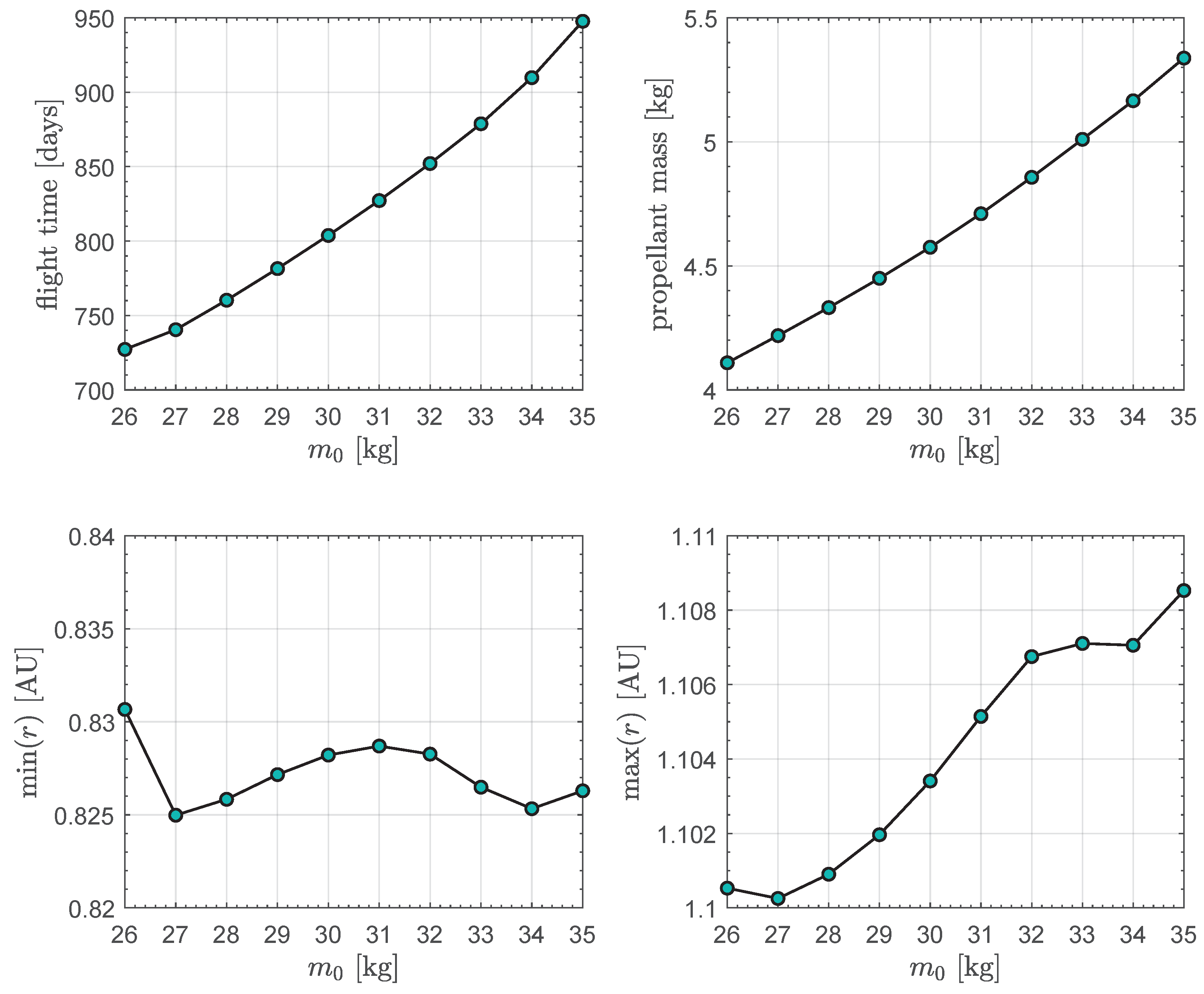
In this reference case, the miniaturized electric thruster gives always the maximum thrust magnitude (i.e., during all the flight), the rapid transfer does not contain any coasting arc and requires a flight time of about , while the required propellant mass is slightly less of . Finally, Figure 7 shows the time variation in the CubeSat mass and the distance from the Sun during the transfer. Note that the solar distance value remains within the allowed range throughout the interplanetary flight. The numerical procedure has been repeated by varying the initial CubeSat mass in the range , with a step of , to perform a sort of parametric study of the transfer performance as a function of . The results are shown in Figure 8, which clearly indicates that the transfer performances, in terms of both the flight time and the required propellant mass, depend on the value of the initial CubeSat mass. In this respect, a reduction in the value of of about (with respect to the reference value of ) allows the flight time to be reduced of roughly .
4. Conclusions
In this paper, the thrust model of a CubeSat equipped with an HPS consisting of a miniaturized electric thruster and a photonic solar sail in a Sun-facing configuration has been analyzed. The proposed mathematical model considers the performance of the miniaturized electric thruster that will be installed on the first interplanetary CubeSat capable of a heliocentric transfer using its own propulsion system, while the performance of the photonic solar sail has been schematized by using the classical optical force model and the design characteristics of the sail installed on NASA’s NEA scout. The HPS model gives an analytical expression of both the thrust vector and the propellant mass flow rate, which can be used to study the CubeSat trajectory in a typical heliocentric mission scenario. In this context, the paper discussed the performance in an orbit-to-orbit transfer from the Earth to asteroid 99942 Apophis. In particular, the optimal performance is calculated in terms of minimum transfer time. However, the proposed thrust model can be used to simulate CubeSat transfers in other interesting mission scenarios where, for example, the performance index to be optimized is a suitable combination of flight time and required propellant mass.
The potential extension of this work can be achieved in two subsequent steps. First, a mathematical model of the CubeSat subsystems mass can be used to determine the actual impact of an HPS on the initial mass of the spacecraft. This will allow us to correctly compare the performance of a conventional spacecraft with a single propulsion system with that of a vehicle equipped with an HPS. Second, the constraint on the Sun-facing condition can be relaxed in order to evaluate the effect of the photonic solar sail attitude variation on the overall interplanetary transfer performance.
Funding
This research received no external funding.
Institutional Review Board Statement
Not applicable.
Informed Consent Statement
Not applicable.
Data Availability Statement
The original contributions presented in the study are included in the article; further inquiries can be directed to the corresponding author.
Conflicts of Interest
The author declares no conflict of interest.
Appendix A. Mathematical Model of the Electric Thruster-Induced Propulsive Acceleration
This appendix reports the thrust model of the (miniaturized) electronic thruster that constitutes a part of the HPS considered in this work. More precisely, this thrust model is derived from the recent work of the author [52], which describes a simplified mathematical approach for the description of the propulsive characteristics of the electric thruster installed on board the proposed ESA’s M-ARGO CubeSat, whose artistic representation is shown in Figure A1. In turn, the mathematical model described in Ref. [52] is an extension of the surrogate engine model recently proposed by Topputo et al. [54] for the preliminary design of the M-ARGO interplanetary trajectory.
In particular, the simplified thrust model described in Ref. [52] gives the expression of the thrust vector and the specific impulse of the M-ARGO’s miniaturized electric thruster as a function of the Sun-CubeSat distance . The constraints on the minimum (i.e., ) and maximum (i.e., ) solar distance are related to the original surrogate model of Topputo et al. [54] (which, in turn, is linked to the admissible value of the thruster input power), and will also be considered in this work during the selection of the potential mission scenario.
Figure A1.
Artistic representation of the ESA’s M-ARGO CubeSat approach to a potential near-Earth asteroid. Image: © ESA.
Figure A1.
Artistic representation of the ESA’s M-ARGO CubeSat approach to a potential near-Earth asteroid. Image: © ESA.

According to Equations (12) and (16) of Ref. [52], and bearing in mind that the electric thruster-induced thrust vector is assumed to be freely steerable during the flight, one obtains the compact expressions of
where is a reference distance which is used to normalize the results of the best-fit procedure described in Ref. [52], is the maximum value of the magnitude of when the solar distance is 1 astronomical unit, is the electric thruster-induced thrust unit vector, and is the dimensionless throttle parameter which models the local thrust magnitude variation between the minimum (when ) and the maximum (when ) value. In essence, the dimensionless parameter models the actual behaviour of a typical electric thruster in which the admissible thrust magnitude levels are given by the classical throttle Table [61]. In Equation (A1), the coefficients appearing in the fraction on the right-hand side are obtained through a best-fit procedure. Their values are given by Equation (13) of Ref. [52], viz.
The approximate expression of the specific impulse is given by Equation (14) of Ref. [52] as a function of the solar distance r. The function is written in a compact form as
where is a reference value of the specific impulse (which coincides with the value of at a solar distance of 1 astronomical unit), while the best-fit coefficients on the fraction at the right-hand side of the equation are
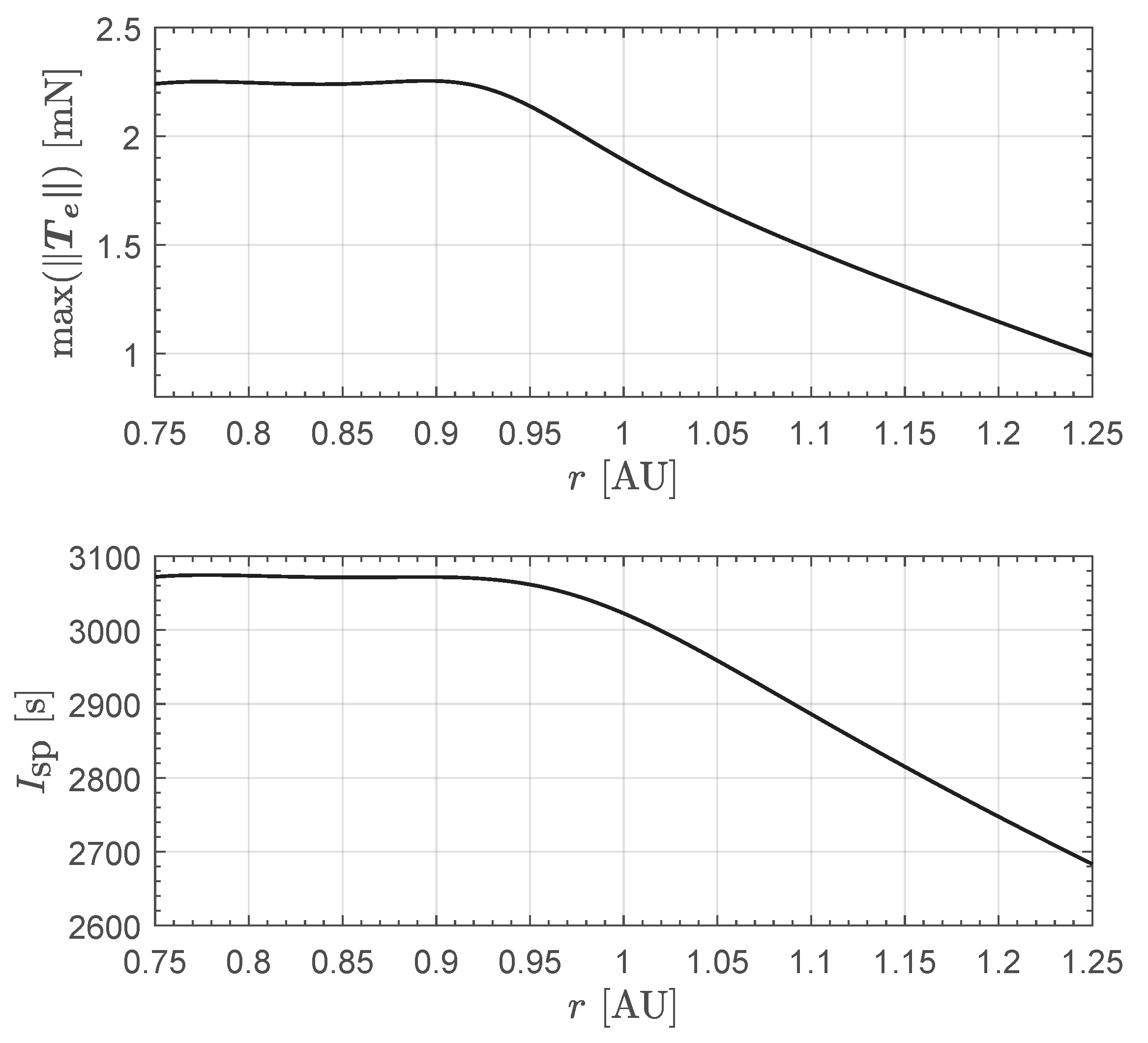
The r-variation of the maximum thrust magnitude and the specific impulse are shown in Figure A2, which is consistent with the graph reported in Figure 4 of Ref. [52]. Equations (A1) and (A3) are used in Section 2 to obtain a simplified version of the HPS thrust vector model. In this regard, the next appendix describes the mathematical approach used to evaluate the contribution of the solar sail to the total propulsive acceleration of the CubeSat.
Figure A2.
Miniaturized electric thruster: variation of and with .
Appendix B. Mathematical Model of the Solar Sail-Induced Propulsive Acceleration
This appendix describes the mathematical model used to schematize the thrust vector due to the presence of the photonic solar sail. In this context, the solar sail is considered as a flat surface, that is, the billowing of the reflective membrane [70] is neglected in evaluating the expression of . The latter is a fairly common assumption in the preliminary design of a solar sail-based trajectory, while recent literature [71] discusses an approach based on the use of finite element analysis to evaluate the impact of sail billowing during the interplanetary flight.
From the point of view of the effect of the thermo-optical characteristics of the reflective membrane, the classical optical force model illustrated by McInnes [72] has been employed. In this respect, using the formulation proposed in Ref. [73] the compact expression of the solar sail-induced thrust vector is
where is the solar radiation pressure exerted on a perfectly absorbing surface at 1 astronomical unit of distance from the Sun, A is the sail reflective surface, is a reference distance, is the Sun-spacecraft radial unit vector, and is the unit vector normal to the sail reflective membrane surface in direction opposite to the Sun. In Equation (A5), the dimensionless terms are the so called “sail force coefficients”, whose values depend on the thermo-optical characteristics of the film which coves the sail membrane. The expressions of the sail force coefficients are [73].
where s is the fraction of photons that are specularly reflected, (or ) is the non-Lambertian coefficient of the front (or back) sail membrane, (or ) is the membrane front (or back) emissivity, and the reflection coefficient.
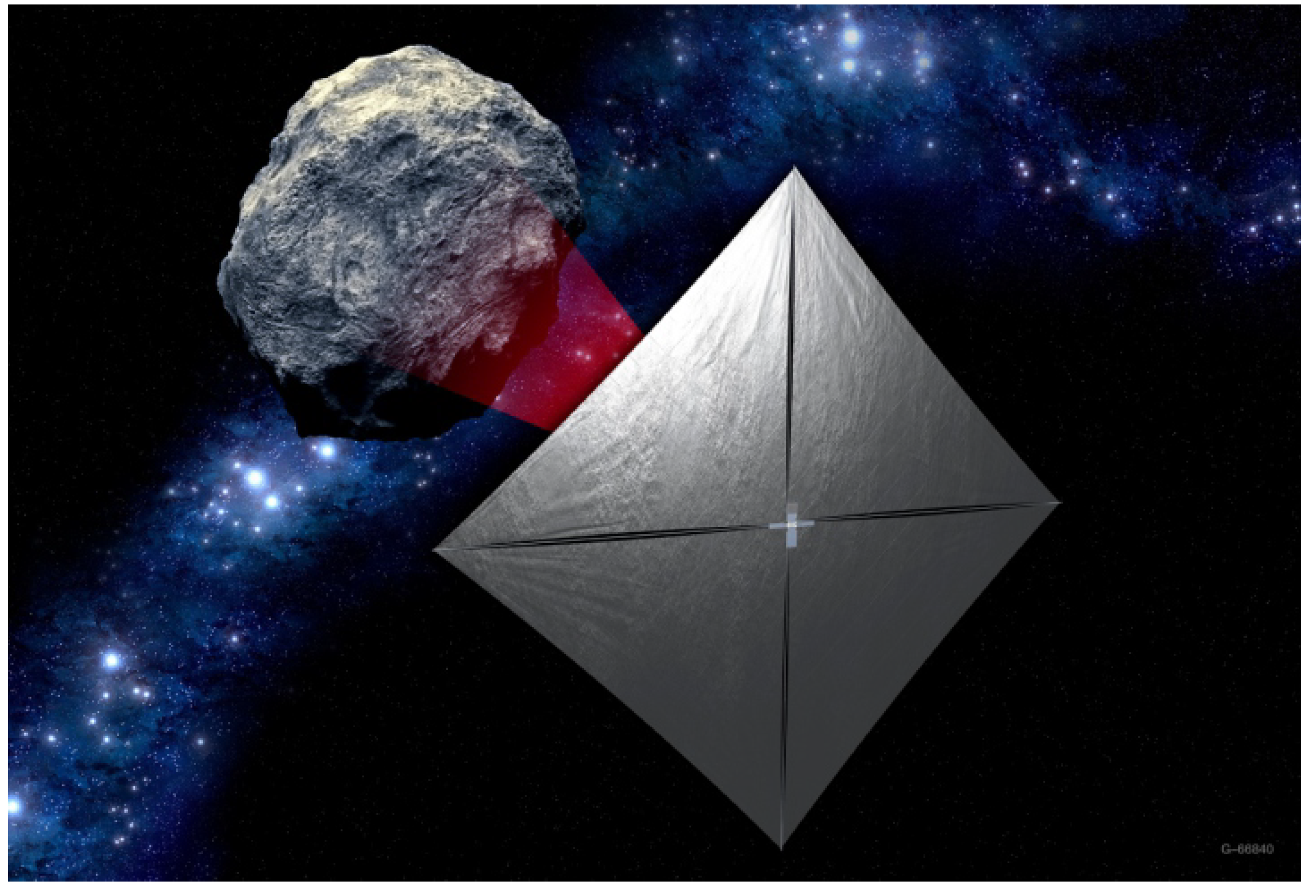
In this work, the photonic solar sail performances are modeled by using the literature data referring to the NASA’s NEA Scout CubeSat; see the artistic image in Figure A3.
Figure A3.
Artistic concept of the NASA’s Near-Earth Asteroid Scout (NEA Scout) approaching the target asteroid. The solar sail-based CubeSat failed to make contact with ground station after launch, and the mission NEA Scout was considered lost in December 2022. Image credit: NASA.
Figure A3.
Artistic concept of the NASA’s Near-Earth Asteroid Scout (NEA Scout) approaching the target asteroid. The solar sail-based CubeSat failed to make contact with ground station after launch, and the mission NEA Scout was considered lost in December 2022. Image credit: NASA.
In this case, the thermo optical coefficients of that (ill-fated) solar sail-based CubeSat are indicated in Refs. [59,60], viz.
so that, according to Equation (A6), the sail force coefficients are
In the special case in which the sail attitude is Sun-facing, that is, the direction of coincides with that of , one has and Equation (A5) simplifies as
where is a dimensionless coefficient that quantifies the effect of the actual thermo-optical characteristics of the sail film with respect to the ideal case of a complete (and specular) reflection in which . In this case, the value of is
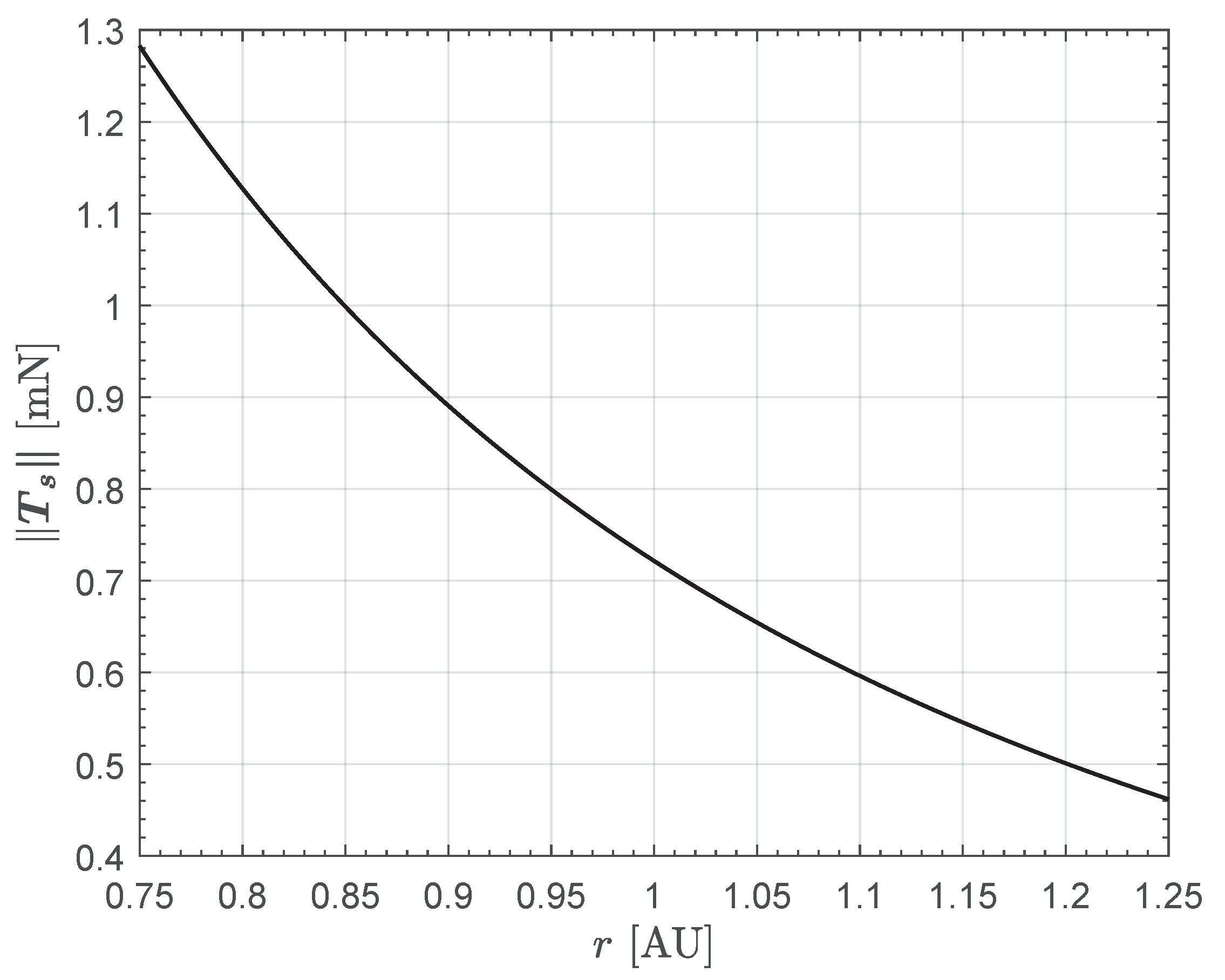
Equation (A9) is used to describe the (Sun-facing) photonic solar sail-induced thrust vector. In this respect, a value of the sail area consistent with the NEA Scout case has been assumed, that is, . Accordingly, the variation with r of the magnitude of the solar sail thrust vector is drawn in Figure A4. Note that at one has . In fact, the NEA Scout propulsive acceleration magnitude at 1 astronomical unit of distance from the Sun was estimated in about and, bearing in mind that the CubeSat mass was , one obtains , as expected.
Finally, note that is of the same order of magnitude as the maximum propulsive thrust generated by the miniaturized electric thruster; compare the upper part of Figure A2 with the graph in Figure A4. This is an important aspect of the analysis, because it indicates that the contribution of the photon solar sail in obtaining the total thrust vector is not negligible.
Figure A4.
Photonic solar sail in a Sun-facing configuration: variation of the thrust magnitude with the solar distance , according to Equation (A9). The solar sail characteristics (in terms of sail area and sail force coefficients) are consistent with the system installed onboard of the NASA’s NEA Scout CubeSat.
References
- Brophy, J.R.; Noca, M. Electric Propulsion for Solar System Exploration. J. Propuls. Power 1998, 14, 700–707. [Google Scholar] [CrossRef]
- Burke, L.M.; Falck, R.D.; McGuire, M.L. Interplanetary Mission Design Handbook: Earth-to-Mars Mission Opportunities 2026 to 2045; techreport NASA/TM—2010-216764; National Aeronautics and Space Administration: Cleveland, OH, USA, 2010. [Google Scholar]
- Urrios, J.; Pacheco-Ramos, G.; Vazquez, R. Optimal planning and guidance for Solar System exploration using Electric Solar Wind Sails. Acta Astronaut. 2024, 217, 116–129. [Google Scholar] [CrossRef]
- Staehle, R.; Blaney, D.; Hemmati, H.; Jones, D.; Klesh, A.; Liewer, P.; Lazio, J.; Wen-Yu Lo, M.; Mouroulis, P.; Murphy, N.; et al. Interplanetary CubeSat Architecture and Missions, In Proceedings of the AIAA SPACE 2012 Conference & Exposition, Pasadena, CA, USA, 11–13 September 2012. [CrossRef]
- Schoolcraft, J.; Klesh, A.; Werne, T. MarCO: Interplanetary Mission Development on a CubeSat Scale. In Space Operations: Contributions from the Global Community; Springer International Publishing: Berlin, Germany, 2017; Chapter 10; pp. 221–231. [Google Scholar] [CrossRef]
- Malphrus, B.K.; Freeman, A.; Staehle, R.; Klesh, A.T.; Walker, R. Interplanetary CubeSat missions. In CubeSat Handbook: From Mission Design to Operations; Cappelletti, C., Battistini, S., Malphrus, B.K., Eds.; Academic Press: London, UK, 2021; Chapter 4; pp. 85–121. [Google Scholar] [CrossRef]
- Freeman, A.; Malphrus, B.K.; Staehle, R. CubeSat science instruments. In CubeSat Handbook: From Mission Design to Operations; Cappelletti, C., Battistini, S., Malphrus, B.K., Eds.; Academic Press: London, UK, 2021; Chapter 3; pp. 67–83. [Google Scholar] [CrossRef]
- Schoolcraft, J.; Klesh, A.T.; Werne, T. MarCO: Interplanetary mission development on a cubesat scale. In Proceedings of the SpaceOps 2016 Conference, Daejeon, Republic of Korea, 16–20 May 2016. [Google Scholar] [CrossRef]
- Klesh, A.T. MARCO: Flight results from the first interplanetary CubeSat mission. In Proceedings of the 70th Annual International Astronautical Congress, Washington, DC, USA, 21–25 October 2019. [Google Scholar]
- Gutierrez, G.; Riccobono, D.; Bruno, E.; Bonariol, T.; Vigna, L.; Reverberi, G.; Fazzoletto, E.; Cotugno, B.; Vitiello, A.; Saita, G.; et al. LICIACube: Mission Outcomes of Historic Asteroid Fly-By Performed by a CubeSat. In Proceedings of the 2024 IEEE Aerospace Conference, Big Sky, MT, USA, 2–9 March 2024. [Google Scholar] [CrossRef]
- Franzese, V.; Topputo, F. Celestial Bodies Far-Range Detection with Deep-Space CubeSats. Sensors 2023, 23, 4544. [Google Scholar] [CrossRef]
- Cervone, A.; Topputo, F.; Franzese, V.; Pérez-Silva, A.R.; Leon, B.B.; Garcia, B.D.; Minacapilli, P.; Rosa, P.; Bay, G.; Radu, S. The path towards increasing RAMS for novel complex missions based on CubeSat technology. CEAS Space J. 2023, 16, 203–224. [Google Scholar] [CrossRef]
- Mitchell, A.M.; Panicucci, P.; Franzese, V.; Topputo, F.; Linares, R. Improved detection of a Near-Earth Asteroid from an interplanetary CubeSat mission. Acta Astronaut. 2024, 223, 685–692. [Google Scholar] [CrossRef]
- Lemmer, K. Propulsion for CubeSats. Acta Astronaut. 2017, 134, 231–243. [Google Scholar] [CrossRef]
- Alnaqbi, S.; Darfilal, D.; Swei, S.S.M. Propulsion Technologies for CubeSats: Review. Aerospace 2024, 11, 502. [Google Scholar] [CrossRef]
- O’Reilly, D.; Herdrich, G.; Kavanagh, D.F. Electric Propulsion Methods for Small Satellites: A Review. Aerospace 2021, 8, 22. [Google Scholar] [CrossRef]
- Yeo, S.H.; Ogawa, H.; Kahnfeld, D.; Schneider, R. Miniaturization perspectives of electrostatic propulsion for small spacecraft platforms. Prog. Aerosp. Sci. 2021, 126, 100742. [Google Scholar] [CrossRef]
- Grönland, T.A.; Rangsten, P.; Nese, M.; Lang, M. Miniaturization of components and systems for space using MEMS-technology. Acta Astronaut. 2007, 61, 228–233. [Google Scholar] [CrossRef]
- Alvara, A.N.; Lee, L.; Sin, E.; Lambert, N.; Westphal, A.J.; Pister, K.S. BLISS: Interplanetary exploration with swarms of low-cost spacecraft. Acta Astronaut. 2024, 215, 348–361. [Google Scholar] [CrossRef]
- Shukla, H.; Velidi, G. Energetic material characterization and ignition study of MEMS based micro-thruster for multi spacecrafts missions. FirePhysChem 2024, 4, 122–130. [Google Scholar] [CrossRef]
- Kabirov, V.; Semenov, V.; Torgaeva, D.; Otto, A. Miniaturization of spacecraft electrical power systems with solar-hydrogen power supply system. Int. J. Hydrogen Energy 2023, 48, 9057–9070. [Google Scholar] [CrossRef]
- Janhunen, P. Electric sail for spacecraft propulsion. J. Propuls. Power 2004, 20, 763–764. [Google Scholar] [CrossRef]
- Janhunen, P.; Sandroos, A. Simulation study of solar wind push on a charged wire: Basis of solar wind electric sail propulsion. Ann. Geophys. 2007, 25, 755–767. [Google Scholar] [CrossRef]
- Janhunen, P.; Toivanen, P.K.; Polkko, J.; Merikallio, S.; Salminen, P.; Haeggström, E.; Seppänen, H.; Kurppa, R.; Ukkonen, J.; Kiprich, S.; et al. Electric solar wind sail: Toward test missions. Rev. Sci. Instrum. 2010, 81, 111301. [Google Scholar] [CrossRef]
- Bassetto, M.; Niccolai, L.; Quarta, A.A.; Mengali, G. A comprehensive review of Electric Solar Wind Sail concept and its applications. Prog. Aerosp. Sci. 2022, 128, 1–27. [Google Scholar] [CrossRef]
- Gong, S.; Macdonald, M. Review on solar sail technology. Astrodynamics 2019, 3, 93–125. [Google Scholar] [CrossRef]
- Fu, B.; Sperber, E.; Eke, F. Solar sail technology—A state of the art review. Prog. Aerosp. Sci. 2016, 86, 1–19. [Google Scholar] [CrossRef]
- Tsuda, Y.; Mori, O.; Funase, R.; Sawada, H.; Yamamoto, T.; Saiki, T.; Endo, T.; Kawaguchi, J. Flight status of IKAROS deep space solar sail demonstrator. Acta Astronaut. 2011, 69, 833–840. [Google Scholar] [CrossRef]
- Tsuda, Y.; Mori, O.; Funase, R.; Sawada, H.; Yamamoto, T.; Saiki, T.; Endo, T.; Yonekura, K.; Hoshino, H.; Kawaguchi, J. Achievement of IKAROS—Japanese deep space solar sail demonstration mission. Acta Astronaut. 2013, 82, 183–188. [Google Scholar] [CrossRef]
- Mughal, M.R.; Praks, J.; Vainio, R.; Janhunen, P.; Envall, J.; Näsilä, A.; Oleynik, P.; Niemelä, P.; Nyman, S.; Slavinskis, A.; et al. Aalto-1, multi-payload CubeSat: In-orbit results and lessons learned. Acta Astronaut. 2021, 187, 557–568. [Google Scholar] [CrossRef]
- Dalbins, J.; Allaje, K.; Iakubivskyi, I.; Kivastik, J.; Komarovskis, R.O.; Plans, M.; Sünter, I.; Teras, H.; Ehrpais, H.; Ilbis, E.; et al. ESTCube-2: The Experience of Developing a Highly Integrated CubeSat Platform. In Proceedings of the 2022 IEEE Aerospace Conference (AERO), Big Sky, MT, USA, 5–12 March 2022; pp. 1–16. [Google Scholar] [CrossRef]
- Palos, M.F.; Janhunen, P.; Toivanen, P.; Tajmar, M.; Iakubivskyi, I.; Micciani, A.; Orsini, N.; Kütt, J.; Rohtsalu, A.; Dalbins, J.; et al. Electric Sail Mission Expeditor, ESME: Software Architecture and Initial ESTCube Lunar Cubesat E-sail Experiment Design. Aerospace 2023, 10, 694. [Google Scholar] [CrossRef]
- Boni, L.; Bassetto, M.; Niccolai, L.; Mengali, G.; Quarta, A.A.; Circi, C.; Pellegrini, R.C.; Cavallini, E. Structural response of Helianthus solar sail during attitude maneuvers. Aerosp. Sci. Technol. 2023, 133, 1–9. [Google Scholar] [CrossRef]
- Zhao, P.; Wu, C.; Li, Y. Design and application of solar sailing: A review on key technologies. Chin. J. Aeronaut. 2023, 36, 125–144. [Google Scholar] [CrossRef]
- Berg, S.P.; Rovey, J.L. Assessment of Multimode Spacecraft Micropropulsion Systems. J. Spacecr. Rocket. 2017, 54, 592–601. [Google Scholar] [CrossRef]
- Rovey, J.L.; Lyne, C.T.; Mundahl, A.J.; Rasmont, N.; Glascock, M.S.; Wainwright, M.J.; Berg, S.P. Review of multimode space propulsion. Prog. Aerosp. Sci. 2020, 118, 100627. [Google Scholar] [CrossRef]
- Vulpetti, G. Missions to the heliopause and beyond by staged propulsion spacecrafts. In Proceedings of the 43rd International Astronautical Congress, Washington, DC, USA, 28 August–5 September 1992. [Google Scholar]
- Baig, S.; McInnes, C.R. Artificial Three-Body Equilibria for Hybrid Low-Thrust Propulsion. J. Guid. Control. Dyn. 2008, 31, 1644–1655. [Google Scholar] [CrossRef]
- Li, T.; Wang, Z.; Zhang, Y. Multi-objective trajectory optimization for a hybrid propulsion system. Adv. Space Res. 2018, 62, 1102–1113. [Google Scholar] [CrossRef]
- Mengali, G.; Quarta, A.A. Tradeoff performance of hybrid low-thrust propulsion system. J. Spacecr. Rocket. 2007, 44, 1263–1270. [Google Scholar] [CrossRef]
- Mengali, G.; Quarta, A.A. Trajectory design with hybrid low-thrust propulsion system. J. Guid. Control. Dyn. 2007, 30, 419–426. [Google Scholar] [CrossRef]
- Mengali, G.; Quarta, A.A. Trajectory analysis and optimization of Hesperides mission. Universe 2022, 8, 364. [Google Scholar] [CrossRef]
- Ceriotti, M.; McInnes, C.R. Hybrid solar sail and solar electric propulsion for novel Earth observation missions. Acta Astronaut. 2011, 69, 809–821. [Google Scholar] [CrossRef]
- Ceriotti, M.; McInnes, C.R. An Earth pole-sitter using hybrid propulsion. In Proceedings of the AIAA/AAS Astrodynamics Specialist Conference, Toronto, Canada, 2–5 August 2010. [Google Scholar] [CrossRef]
- Ceriotti, M.; McInnes, C.R. Generation of optimal trajectories for Earth hybrid pole sitters. J. Guid. Control. Dyn. 2011, 34, 847–859. [Google Scholar] [CrossRef]
- Matloff, G.L. The solar photon thruster as a terrestrial pole sitter. Ann. N. Y. Acad. Sci. 2004, 1017, 468–474. [Google Scholar] [CrossRef]
- Dachwald, B.; Seboldt, W.; Macdonald, M.; Mengali, G.; Quarta, A.; McInnes, C.; Rios-Reyes, L.; Scheeres, D.; Wie, B.; Görlich, M.; et al. Potential Solar Sail Degradation Effects on Trajectory and Attitude Control. In Proceedings of the AIAA Guidance, Navigation, and Control Conference and Exhibit, San Francisco, CA, USA, 15–18 August, 2005. [Google Scholar] [CrossRef]
- Dachwald, B.; Macdonald, M.; McInnes, C.R.; Mengali, G.; Quarta, A.A. Impact of optical degradation on solar sail mission performance. J. Spacecr. Rocket. 2007, 44, 740–749. [Google Scholar] [CrossRef]
- McInnes, C.R. Orbits in a Generalized Two-Body Problem. J. Guid. Control. Dyn. 2003, 26, 743–749. [Google Scholar] [CrossRef]
- Mengali, G.; Quarta, A.A. Optimal control laws for axially symmetric solar sails. J. Spacecr. Rocket. 2005, 42, 1130–1133. [Google Scholar] [CrossRef]
- Li, Y.; Cheah, K.H. Solar sail as propellant-less micropropulsion. In Space Micropropulsion for Nanosatellites; Cheah, K.H., Ed.; Elsevier: Amsterdam, The Netherlands, 2022; Chapter 10; pp. 273–284. [Google Scholar] [CrossRef]
- Quarta, A.A. Continuous-Thrust Circular Orbit Phasing Optimization of Deep Space CubeSats. Appl. Sci. 2024, 14, 7059. [Google Scholar] [CrossRef]
- Franzese, V.; Topputo, F.; Ankersen, F.; Walker, R. Deep-Space Optical Navigation for M-ARGO Mission. J. Astronaut. Sci. 2021, 68, 1034–1055. [Google Scholar] [CrossRef]
- Topputo, F.; Wang, Y.; Giordano, C.; Franzese, V.; Goldberg, H.; Perez-Lissi, F.; Walker, R. Envelop of reachable asteroids by M-ARGO CubeSat. Adv. Space Res. 2021, 67, 4193–4221. [Google Scholar] [CrossRef]
- Franzese, V.; Giordano, C.; Wang, Y.; Topputo, F.; Goldberg, H.; Gonzalez, A.; Walker, R. Target selection for M-ARGO interplanetary cubesat. In Proceedings of the 71st International Astronautical Congress, Virtual Event, 12–14 October 2020. [Google Scholar]
- McNutt, L.; Johnson, L.; Clardy, D.; Castillo-Rogez, J.; Frick, A.; Jones, L. Near-earth asteroid scout. In Proceedings of the AIAA SPACE 2014 Conference and Exposition, San Diego, CA, USA, 4–7 August 2014. [Google Scholar]
- Johnson, L.; Castillo-Rogez, J.; Lockett, T. Near Earth asteroid Scout: Exploring asteroid 1991VG using a Smallsat. In Proceedings of the 70th International Astronautical Congress, Washington, DC, USA, 21–25 October 2019. [Google Scholar]
- Lockett, T.R.; Castillo-Rogez, J.; Johnson, L.; Matus, J.; Lightholder, J.; Marinan, A.; Few, A. Near-Earth Asteroid Scout Flight Mission. IEEE Aerosp. Electron. Syst. Mag. 2020, 35, 20–29. [Google Scholar] [CrossRef]
- Heaton, A.; Miller, K.; Ahmad, N. Near earth asteroid Scout solar sail thrust and torque model. In Proceedings of the 4th International Symposium on Solar Sailing (ISSS 2017), Kyoyo, Japan, 17–20 January 2017. [Google Scholar]
- Pezent, J.; Sood, R.; Heaton, A. High-fidelity contingency trajectory design and analysis for NASA’s near-earth asteroid (NEA) Scout solar sail Mission. Acta Astronaut. 2019, 159, 385–396. [Google Scholar] [CrossRef]
- Quarta, A.A.; Mengali, G.; Bassetto, M. Rapid orbit-to-orbit transfer to asteroid 4660 Nereus using Solar Electric Propulsion. Universe 2023, 9, 459. [Google Scholar] [CrossRef]
- Fan, Z.; Huo, M.; Quarta, A.A.; Mengali, G.; Qi, N. Improved Monte Carlo Tree Search-based Approach to Low-thrust Multiple Gravity assist Trajectory Design. Aerosp. Sci. Technol. 2022, 130, 1–8. [Google Scholar] [CrossRef]
- Bryson, A.E.; Ho, Y.C. Applied Optimal Control; Hemisphere Publishing Corporation: New York, NY, USA, 1975; Chapter 2; pp. 71–89. ISBN 0-891-16228-3. [Google Scholar]
- Stengel, R.F. Optimal Control and Estimation; Dover Books on Mathematics, Dover Publications, Inc.: New York, NY, USA, 1994; pp. 222–254. [Google Scholar]
- Ross, I.M. A Primer on Pontryagin’s Principle in Optimal Control; Collegiate Publishers: San Francisco, CA, USA, 2015; Chapter 2; pp. 127–129. [Google Scholar]
- Prussing, J.E. Optimal Spacecraft Trajectories; Oxford University press: Oxford, UK, 2018; Chapter 4; pp. 32–40. [Google Scholar]
- Prussing, J.E. Spacecraft Trajectory Optimization; Cambridge University Press: Cambridge, UK, 2010; Chapter 2; pp. 16–36. [Google Scholar] [CrossRef]
- Walker, M.J.H.; Ireland, B.; Owens, J. A set of modified equinoctial orbit elements. Celest. Mech. 1985, 36, 409–419, Erratum in Celest. Mech. 1986, 38, 391–392. [Google Scholar] [CrossRef]
- Quarta, A.A. Initial costate approximation for rapid orbit raising with very low propulsive acceleration. Appl. Sci. 2024, 14, 1124. [Google Scholar] [CrossRef]
- Boni, L.; Bassetto, M.; Quarta, A.A. Characterization of a solar sail membrane for Abaqus-Based Simulations. Aerospace 2024, 11, 151. [Google Scholar] [CrossRef]
- Boni, L.; Mengali, G.; Quarta, A.A. Finite Element Analysis of Solar Sail Force Model with Mission Application. Proc. Inst. Mech. Eng. Part G J. Aerosp. Eng. 2019, 233, 1838–1846. [Google Scholar] [CrossRef]
- McInnes, C.R. Solar Sailing: Technology, Dynamics and Mission Applications; Springer-Praxis Series in Space Science and Technology; Springer-Verlag: Berlin, Germany, 1999; pp. 46–54. [Google Scholar] [CrossRef]
- Mengali, G.; Quarta, A.A. Optimal three-dimensional interplanetary rendezvous using nonideal solar sail. J. Guid. Control. Dyn. 2005, 28, 173–177. [Google Scholar] [CrossRef]
Figure 1.
Variation with of the auxiliary function F defined in Equation (2).
Figure 1.
Variation with of the auxiliary function F defined in Equation (2).
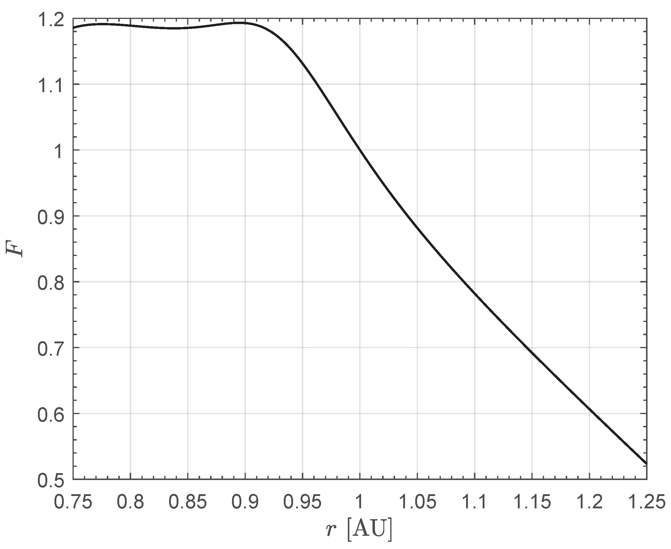
Figure 2.
Variation with of the maximum magnitude of the HPS-induced thrust vector .
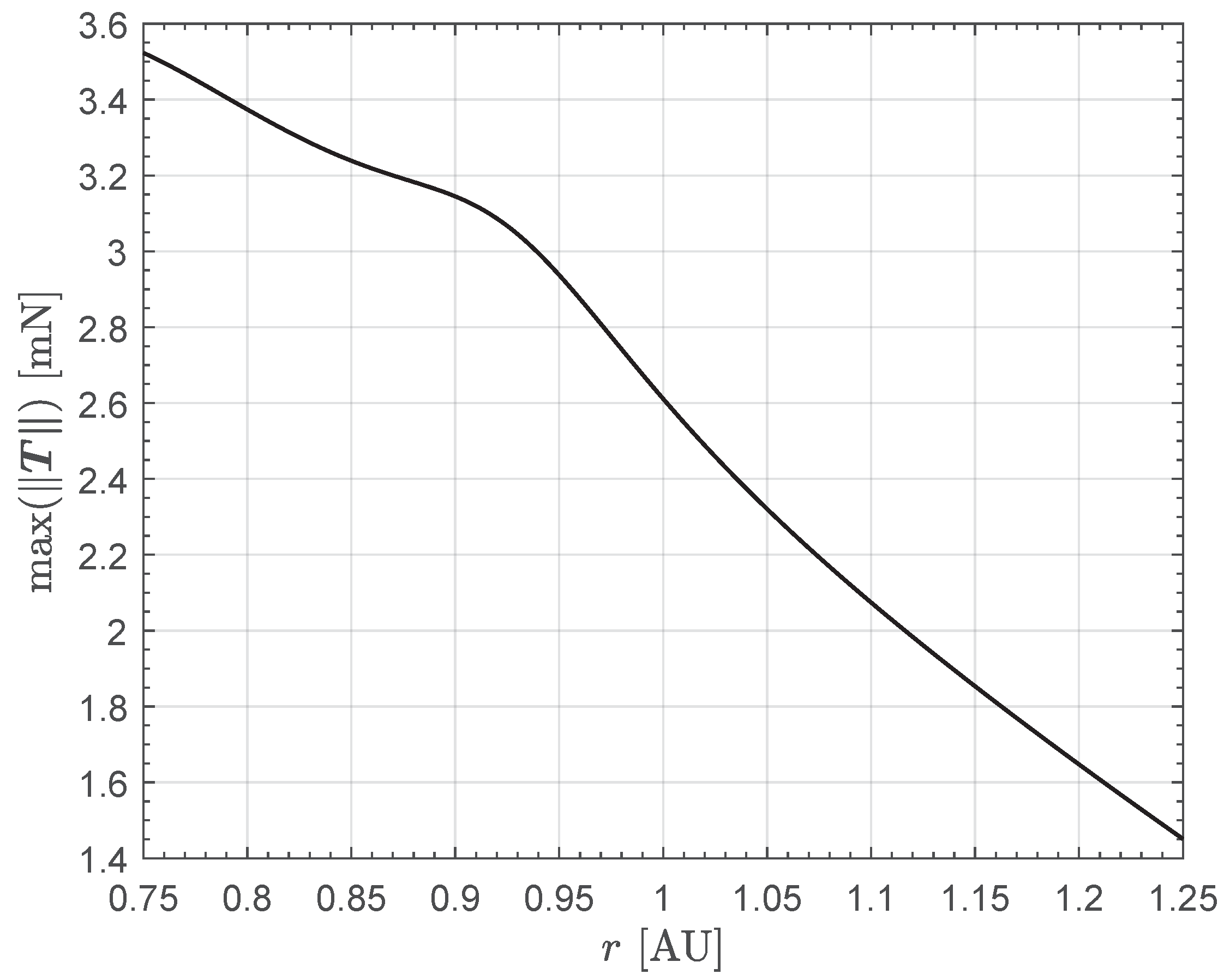
Figure 3.
Thrust bubble (when ) as a function of the Sun-CubeSat distance r. The ticks in the color bar are in millinewtons. (a) Case of ; (b) Case of ; (c) Case of .
Figure 3.
Thrust bubble (when ) as a function of the Sun-CubeSat distance r. The ticks in the color bar are in millinewtons. (a) Case of ; (b) Case of ; (c) Case of .

Figure 4.
Variation with of propellant mass flow rate when the throttle function is ; see the right side of Equation (9).
Figure 4.
Variation with of propellant mass flow rate when the throttle function is ; see the right side of Equation (9).
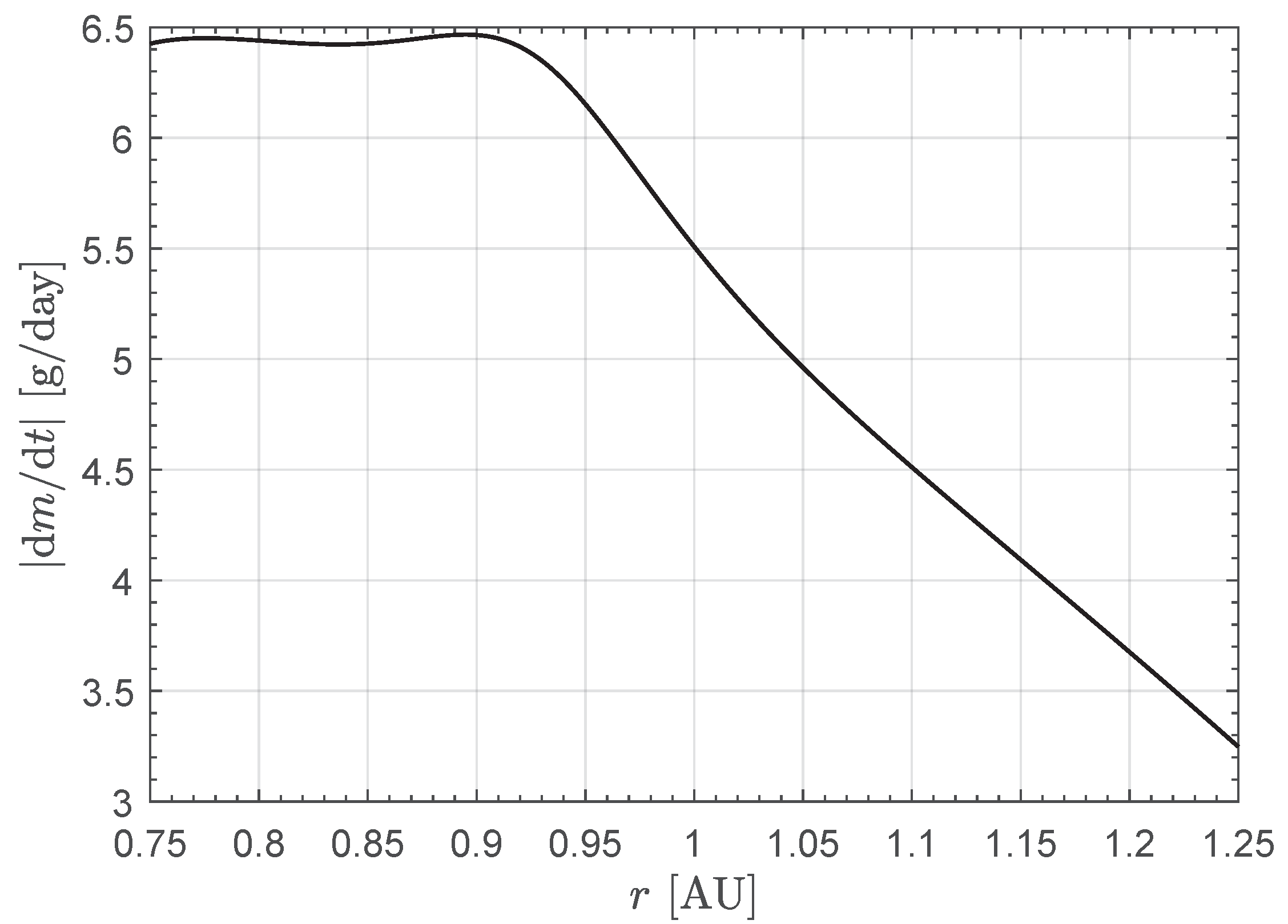
Figure 5.
Ecliptic projection and isometric view of the rapid transfer trajectory towards asteroid 99942 Apophis when the initial CubeSat mass is . The z-axis of the isometric view is exaggerated to highlight the three-dimensionality of the trajectory. Black line → CubeSat transfer trajectory; blue line → Earth’s orbit; red line → asteroid’s orbit; filled star → perihelion; blue dot → starting point; red square → arrival point; orange dot → the Sun.
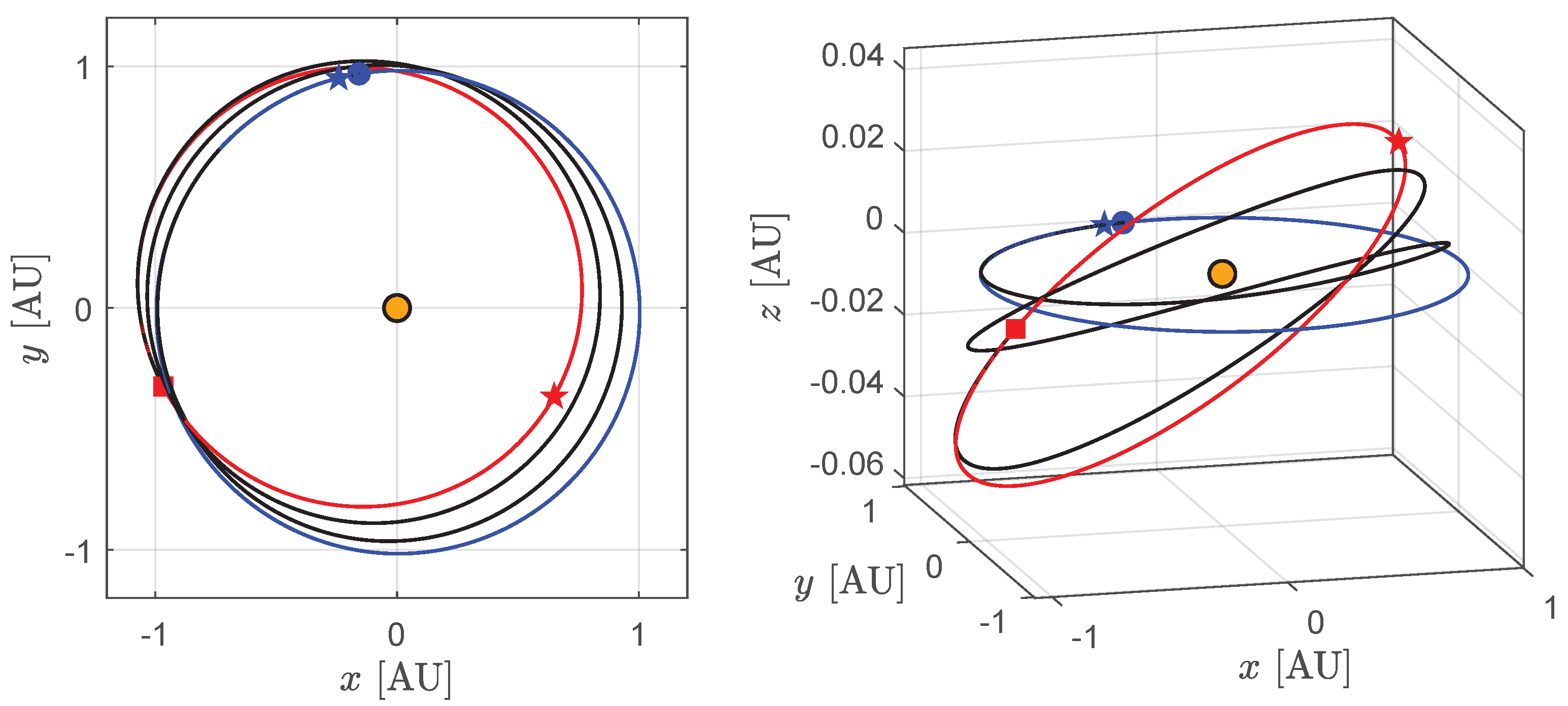
Figure 6.
Time variation in the thrust angles and along the rapid transfer trajectory towards asteroid 99942 Apophis when the initial CubeSat mass is . Blue dot → starting point; red square → arrival point.
Figure 6.
Time variation in the thrust angles and along the rapid transfer trajectory towards asteroid 99942 Apophis when the initial CubeSat mass is . Blue dot → starting point; red square → arrival point.
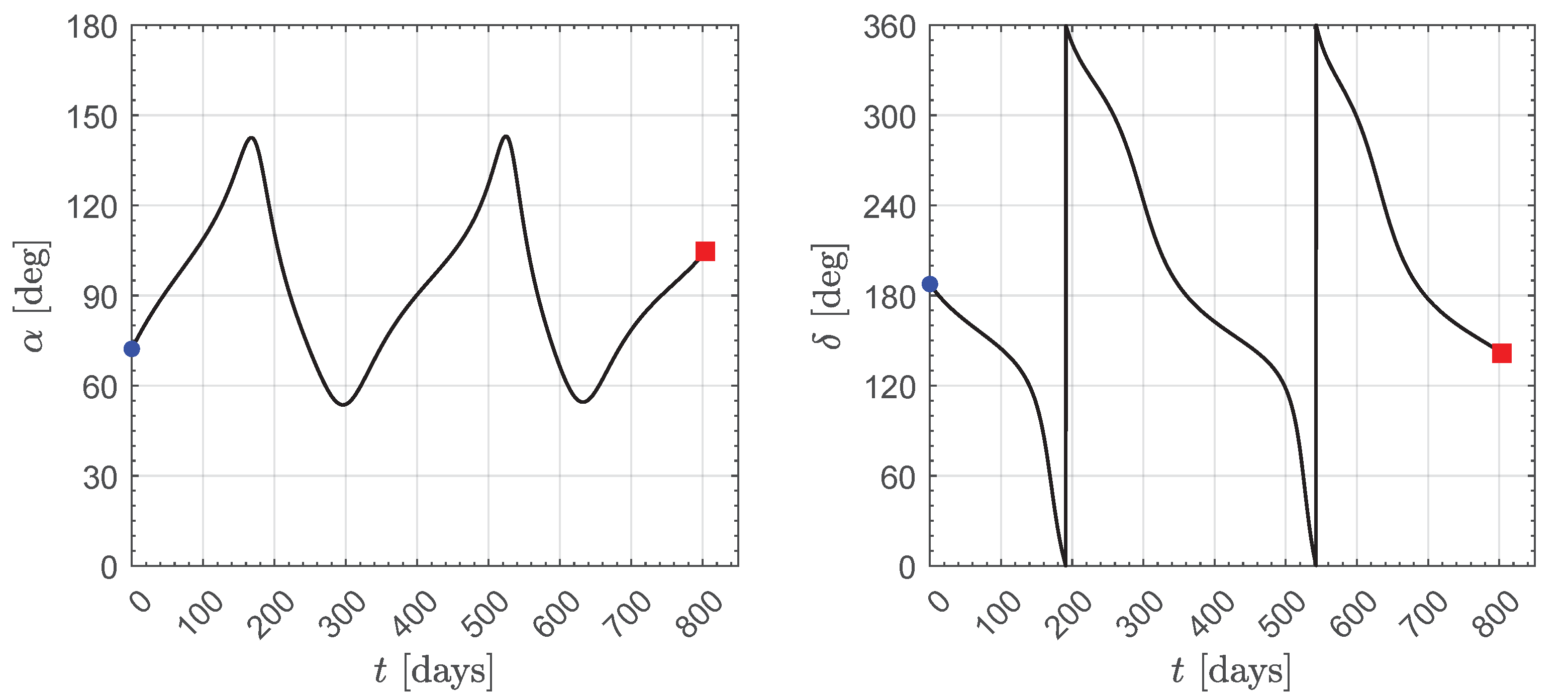
Figure 7.
Time variation in the mass m and solar distance r along the rapid transfer trajectory towards asteroid 99942 Apophis when the initial CubeSat mass is . Blue dot → starting point; red square → arrival point.
Figure 7.
Time variation in the mass m and solar distance r along the rapid transfer trajectory towards asteroid 99942 Apophis when the initial CubeSat mass is . Blue dot → starting point; red square → arrival point.
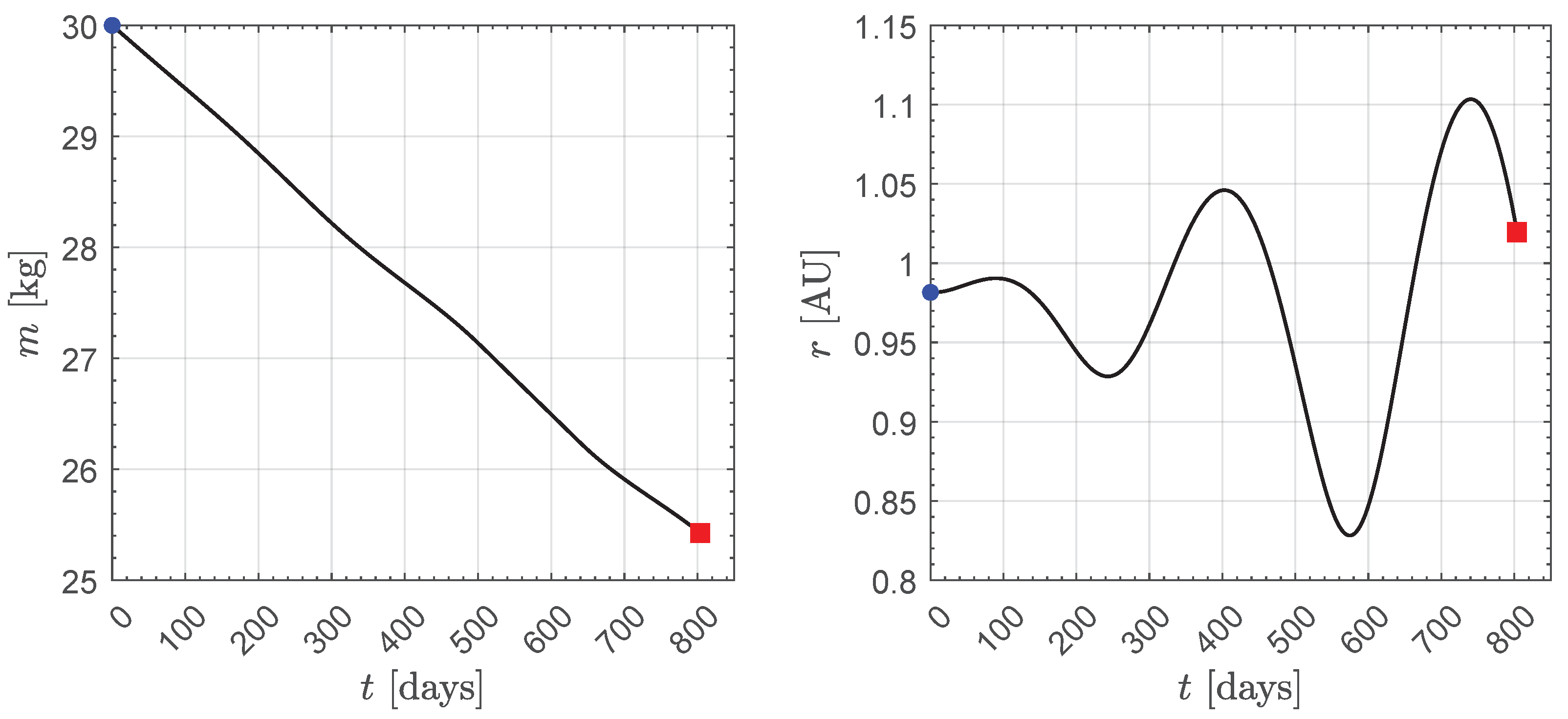
Figure 8.
Results of the parametric study of the Earth–Apophis, orbit-to-orbit, rapid transfer as a function of the value of the initial CubeSat mass (step of , green dots).
Figure 8.
Results of the parametric study of the Earth–Apophis, orbit-to-orbit, rapid transfer as a function of the value of the initial CubeSat mass (step of , green dots).
Disclaimer/Publisher’s Note: The statements, opinions and data contained in all publications are solely those of the individual author(s) and contributor(s) and not of MDPI and/or the editor(s). MDPI and/or the editor(s) disclaim responsibility for any injury to people or property resulting from any ideas, methods, instructions or products referred to in the content. |
© 2024 by the author. Licensee MDPI, Basel, Switzerland. This article is an open access article distributed under the terms and conditions of the Creative Commons Attribution (CC BY) license (https://creativecommons.org/licenses/by/4.0/).
Share and Cite
MDPI and ACS Style
Quarta, A.A. Thrust Model and Trajectory Design of an Interplanetary CubeSat with a Hybrid Propulsion System. Actuators 2024, 13, 384. https://doi.org/10.3390/act13100384
AMA Style
Quarta AA. Thrust Model and Trajectory Design of an Interplanetary CubeSat with a Hybrid Propulsion System. Actuators. 2024; 13(10):384. https://doi.org/10.3390/act13100384
Chicago/Turabian StyleQuarta, Alessandro A. 2024. "Thrust Model and Trajectory Design of an Interplanetary CubeSat with a Hybrid Propulsion System" Actuators 13, no. 10: 384. https://doi.org/10.3390/act13100384
Note that from the first issue of 2016, this journal uses article numbers instead of page numbers. See further details here.
Article Metrics
Article metric data becomes available approximately 24 hours after publication online.