Article

A Disturbance Observer-Based Fractional-Order Fixed-Time Sliding Mode Control Approach for Elevators

1
College of Information Engineering, Zhejiang University of Technology, Hangzhou 310000, China
2
Zhejiang Academy of Special Equipment Science, Hangzhou 310009, China
3
Key Laboratory of Special Equipment Safety Testing Technology of Zhejiang Province, Hangzhou 310016, China
4
Jiaxing Special Equipment Inspection and Testing Institute, Jiaxing 314050, China
*
Author to whom correspondence should be addressed.
Actuators 2024, 13(11), 438; https://doi.org/10.3390/act13110438
Submission received: 5 September 2024 / Revised: 24 October 2024 / Accepted: 29 October 2024 / Published: 1 November 2024
(This article belongs to the Section Control Systems)

Abstract

:
For elevators, appropriate speed control is pivotal for ensuring the safety and comfort of passengers and optimizing energy efficiency, system stability, and service life. Therefore, the design and implementation of effective speed control strategies are crucial for the operation and management of modern elevator systems. In response to this issue, this paper establishes a dynamic model of an elevator through mechanism analysis. Then, a novel fractional-order sliding mode control strategy with the assistance of a fixed-time adaptive sliding mode observer is proposed. The designed observer can effectively monitor and counteract external perturbations, thereby enhancing the stability and precision of the control system. The fractional-order sliding mode controller can realize a fixed-time convergence property, which is rigorously proven in the sense of Lyapunov. Finally, the effectiveness and superiority of the control scheme are validated by simulations compared with benchmark controllers.

1. Introduction

With the acceleration of global urbanization and the rapid increase in high-rise buildings, elevators have become the most widely utilized vertical vehicle in high-rise buildings and are playing an indispensable role in human daily life [1,2]. The unavoidable reliance on elevators, especially in high-rise buildings, requires them to operate consistently, reliably, efficiently, and with sufficient ride comfort [3]. Therefore, the design of control strategies for elevator systems has emerged as a significant research domain, with implications that extend to passenger safety, comfort, operational efficiency, and overall energy consumption of buildings [4].
Traditional elevator control systems usually rely on PID control noted for their simplicity and ease of implementation [5,6,7]. However, in complex practical application scenarios, the performance of PID control normally falls short, which is embodied in the difficulty of guaranteeing high precision and fast response rate. The robustness and adaptability of the PID control are notably inadequate, especially under the effect of load variations, changes in the rope elasticity coefficient, and external disturbances [8]. For example, when the elevator transitions from standby to operational mode, limited by the weak capability of PID control in handling external uncertain perturbations, the imbalances existing in the torques applied to the pulley affect the comfort and safety of passengers to a large extent.
To address these issues, researchers have developed more sophisticated control strategies. Rajaraman et al. utilize two thyristors and two diodes in a power control circuit to realize stepless control of acceleration and deceleration, providing a simpler and less costly alternative to DC motor-driven elevators [9]. Yu et al. demonstrate the superiority of a designed fuzzy-logic control approach over PI control in enhancing the speed-tracking performance of elevator drive systems [10]. Zhang et al. propose a variable-theory-domain fuzzy control method for horizontal vibration suppression of high-rise elevators equipped with magnetorheological dampers [11]. Although these methods improve the control performance of elevators, they also have drawbacks such as large computational burden, high hardware requirements, and difficulty in guaranteeing real-time performance. Thus, it is still necessary to develop more advanced and effective control schemes for elevators to overcome these shortcomings.
Sliding mode control (SMC) possesses the potential to become an appropriate solution, owing to its rapid response, high tracking accuracy, and firm robustness against system uncertainties and external perturbations. SMC normally operates discontinuous control inputs to drive the system state along a predetermined sliding surface and make it converge to the equilibrium point [12]. Due to its specific mechanism and merits, SMC is a popular control method for mechatronic systems such as vehicle steer-by-wire systems [13,14], synchronous reluctance motors [15], omnidirectional mobile robots [16], and agricultural mobile robots [17]. Some studies have also demonstrated the effectiveness of dynamic sliding mode control in addressing uncertainties, time delays, and external disturbances in complex systems, further highlighting the adaptability of SMC [18].
Recently, numerous researchers have focused on integrating fractional calculus with various control strategies, such as PID and SMC. These advanced control techniques have been successfully applied across a wide range of systems, including quadrotor drones [19], robotic arms [20], parallel robots [21], and linear motors [22]. Fractional-order controllers enable more refined tuning of both time and frequency responses in closed-loop control systems. In the field of control and automation, fractional calculus is highly valued for enhancing controller flexibility by providing additional degrees of freedom [21]. Furthermore, applying fractional derivatives and integrals offers some advantages in control applications, such as robust resistance to uncertainties and external disturbances, rapid response, avoidance of singularities, and quick convergence [19,20]. With the development of fractional-order calculus theory, fractional-order sliding mode control (FOSMC) has received increasing attention from scholars [23,24,25]. FOSMC owns unique advantages owing to its fractional-order mechanism, including the attenuation of overshoots and the flexibility in adjusting sliding-surface parameters [26].
Aiming at the practical demands of an elevator control system, this paper proposes a fixed-time sliding mode control strategy based on fractional-order calculus theory. The proposed control scheme also employs an adaptive sliding mode observer to estimate and compensate for real-time disturbances, such that the control precision and robustness can be enhanced. The main contributions of this paper can be summarized as follows:
  • A fixed-time convergent sliding mode control strategy based on fractional-order calculus theory is newly proposed for elevators to enhance the speed control performance.
  • An adaptive sliding mode disturbance observer is introduced to effectively monitor and counteract external disturbances in the elevator system to improve control performance further.
  • The superiority of the proposed scheme is verified by detailed simulation results in different scenarios compared with mainstream benchmark controllers.
The rest parts of this paper are organized as follows. Section 2 establishes a dynamic model of an elevator and provides several definitions and lemmas for the subsequent controller design and stability proof. In Section 3, the fixed-time sliding mode disturbance observer is designed and theoretically analyzed. In Section 4, the fixed-time FOSMC algorithm is designed, and the stability of the control system is verified rigorously. Section 5 shows the simulation results of the proposed control scheme and benchmark controllers, and these results are compared and analyzed. Finally, Section 6 concludes this paper.

2. Modeling and Preliminaries

2.1. Dynamic Modeling of Elevator System

The mechanical construction of elevators varies according to their rated speed and maximum load-bearing capacity. Generally, an elevator with moderate to low speeds (less than 250 m/min) mainly consists of four components: a traction machine, an elevator car, a traction sling, and a counterweight. The elevator car is responsible for transporting passengers or goods vertically. At the same time, the counterweight serves to balance the car mass, thereby reducing the torques needed for the machinery to operate efficiently. A motor is utilized to drive the pulley surrounded by the sling, which connects the elevator car and the counterweight. The mechanical structure of the elevator system is depicted by a simplified schematic, as shown in Figure 1. Then, a dynamic model of the elevator system can be established by integrating Newton’s law with Hooke’s law via force analysis.
As elaborated in [27], due to the limited overall influence of higher-order harmonics on system vibrations, they can be neglected, and lower-order harmonics are sufficient to approximate the behavior of elevator rope vibrations. Hence, uncertainties in the damping and stiffness coefficients of the elevator ropes are considered in our study. From Newton’s law and the law of elasticity, a kinetic equation for the counterweight side is obtained as follows:
m w x ˙ 1 ( c 1 + Δ c 1 ) ( x 3 R x 1 ) ( d 1 + Δ d 1 ) ( x ˙ 3 R x ˙ 1 ) = 0
where x 1 is the displacement of the counterweight, x 3 is the mechanical position of the traction pulley; d 1 , c 1 denote the stiffness coefficient and damping coefficient of the sling on the counterweight side, Δ d 1 and Δ c 1 denote their uncertainties; m w is the mass of the counterweight; R represents the radius of the braking pulley.
Likewise, a dynamic equation for the car side of the elevator is given as
m c x ˙ 2 ( c 2 + Δ c 2 ) ( x 3 R x 2 ) ( d 2 + Δ d 2 ) ( x ˙ 3 R x ˙ 2 ) = 0
where x 2 , m c denote the displacement and mass of the elevator car, respectively; d 2 , c 2 represent the stiffness coefficient and damping coefficient of the sling on the car side, and Δ d 2 and Δ c 2 denote the corresponding uncertainties.
Afterward, a dynamic equation of the traction pulley is achieved as follows:
x ¨ 3 = H J x ˙ 3 + 1 J T e 1 J T d
where H is the inertial deviation moment of inertia, J is the moment of inertia, T e is the electromagnetic torque generated by the traction machine, and T d denotes the compound interference torque.
Setting x = [ x 1 x ˙ 1 x 2 x ˙ 2 x 3 x ˙ 3 ] T as the state vector and u = T e as the control input, a state-space model of the elevator system can be expressed as
x ˙ = A ( Δ ) x + B u + d
where A ( Δ ) is the state matrix, B is the input matrix, d represents the bounded external disturbances, and the expression of A ( Δ ) is
A ( Δ ) = G 1 ( Δ ) G 2 ( Δ ) 0 G 3 ( Δ )
G 1 ( Δ ) = c 1 + Δ c 1 m w + d 1 + Δ d 1 0 0 0 c 1 + Δ c 1 m w + d 1 + Δ d 1 0 0 0 c 2 + Δ c 2 m c + d 2 + Δ d 2
G 2 ( Δ ) = 0 ( c 1 + Δ c 1 ) R m w + ( d 1 + Δ d 1 ) ( d 1 + Δ d 1 ) R m w + ( d 1 + Δ d 1 ) 0 0 ( c 1 + Δ c 1 ) R m w + ( d 1 + Δ d 1 ) H J ( d 1 + Δ d 1 ) R m w + ( d 1 + Δ d 1 ) 0 c 2 R m c + ( d 2 + Δ d 2 ) d 2 R m c + ( d 2 + Δ d 2 )
G 3 ( Δ ) = c 2 + Δ c 2 m c + ( d 2 + Δ d 2 ) 0 ( c 2 + Δ c 2 ) R m c + ( d 2 + Δ d 2 ) H J d 2 R m c + ( d 2 + Δ d 2 ) 0 0 1 0 0 H J .
Let A ( Δ ) = A + Δ A , where A is the matrix calculated from the nominal values, and Δ A represents the model uncertainty matrix in A. The state-space model can therefore be rewritten as
x ˙ = ( A + Δ A ) x + B u + d = A x + B u + d + Δ A x .
Given that the length of the elevator rope is bounded, the velocities of the counterweight and the cabin are also bounded, which implies that the state vector x is bounded. Consequently, d + Δ A x is also bounded. Let D = d + Δ A x , | D | d m a x . Therefore, the dynamic model of the elevator can be expressed as
x ˙ = A x + B u + D
where D is a lumped perturbation term encompassing external environmental disturbances and the uncertainties in dynamic parameters caused by multiple oscillations of the ropes, and the matrix A is given by
A = G 1 G 2 0 G 3
G 1 = c 1 m w + d 1 0 0 0 c 1 m w + d 1 0 0 0 c 2 m c + d 2
G 2 = 0 c 1 R m w + d 1 d 1 R m w + d 1 0 0 c 1 R m w + d 1 H J d 1 R m w + d 1 0 c 2 R m c + d 2 d 2 R m c + d 2
G 3 = c 2 m c + d 2 0 c 2 R m c + d 2 H J d 2 R m c + d 2 0 0 1 0 0 H J
B = 0 1 J 1 m w + d 1 0 1 J 1 m c + d 2 0 1 J T .
Note that the number of passengers in the car is not constant during elevator operation, which results in frequent changes in the load torque of the elevator. The above elevator model conforms to the framework of a linear time-varying system. Specifically, the stiffness and damping coefficients of the elevator slings vary as functions of their instantaneous values during the elevator operation, i.e., parameters such as c 1 , c 2 , d 1 , and d 2 are no longer constants. Furthermore, although mechanical parameters such as J and H are considered to be time-invariant, mismatches with the nominal values also occur under certain operating conditions. These factors may result in deviations between the actual operating conditions and theoretical dynamic models.
Therefore, it is of great significance to explore an effective and robust control strategy to ensure smooth and stable elevator operations.

2.2. Definitions and Lemmas

Definition 1
(Finite-time stability and fixed-time stability [28]). Consider the system
x ˙ = f ( x ) , f ( 0 ) = 0 , x R n
where f ( · ) : R n R n is a continuous function. If the equilibrium point x = 0 of the system (16) is Lyapunov stable and finite-time convergent, then it is a finite-time stable equilibrium point, i.e., there exists a function T ( x 0 ) such that lim t T ( x 0 ) x ( t , x 0 ) = 0 and x ( t , x 0 ) = 0 for all t T ( x 0 ) , where x ( t , x 0 ) = 0 is the solution of the system (16) starting from x ( 0 ) = x 0 . The equilibrium point x = 0 of the system (16) is a fixed-time stable equilibrium point if it is finite-time stable and the convergence time T ( x 0 ) is independent of the initial conditions, i.e., T ( x 0 ) is a constant for all x 0 R n .
Definition 2.
For any α > 0 , x R , a nonlinear function is defined as sig α ( x ) = sgn ( x ) | x | α for the convenience of subsequent controller design and stability proof.
Definition 3
(Riemann–Liouville fractional-order calculus [29]). The cth-order fractional derivative and integration of the function f ( t ) with respect to t and the terminal value t 0 are defined as
D c f t = 1 Γ n c d n d t n t 0 t f τ t τ c n + 1 d τ
I c f t = 1 Γ c t 0 t f τ t τ 1 c d τ
where n 1 < c n , n N , and Γ(·) is called the Gamma function whose expression is given by
Γ ( x ) = 0 + t x 1 e t d t x > 0 .
Lemma 1
([30]). Fractional-order integrals are exchangeable, i.e., for any β , γ > 0 , we have
D β D γ f ( x ) = D β γ f ( x ) .
Proof. 
Due to the properties of double integrals, exchanging the order of integrals yields
D β D γ f ( x ) = 1 Γ ( β ) Γ ( γ ) x 0 x ( x t ) β 1 x 0 t ( t τ ) γ 1 f ( τ ) d τ d t = 1 Γ ( β ) Γ ( γ ) x 0 x τ x ( x t ) β 1 ( t τ ) γ 1 f ( τ ) d t d τ = 1 Γ ( β ) Γ ( γ ) x 0 x f ( τ ) τ x ( x t ) β 1 ( t τ ) γ 1 d t d τ .
Substituting ξ = ( t τ ) ( x τ ) 1 for the variable and bringing it into (21) yields
D β D γ f ( x ) = 1 Γ ( β ) Γ ( γ ) x 0 x ( x τ ) β + γ 1 f ( τ ) 0 1 ( 1 ξ ) β 1 ξ γ 1 d ξ d τ = B ( γ , β ) Γ ( β ) Γ ( γ ) x 0 x ( x τ ) β + γ 1 f ( τ ) d τ = D β γ f ( x )
where B ( γ , β ) is the Beta function, defined as follows:
B ( γ , β ) = Δ 0 1 τ γ 1 ( 1 τ ) β 1 d τ ( γ , β > 0 ) .
Lemma 2
([31]). For a fractional-order integration operation I α f ( t ) , the following inequality holds:
| I α f ( t ) | γ | f ( t ) |
where γ > 0 is a constant.
Lemma 3
([32]). Set a , b , p , q R + , a , b > 0 , p > 1 , 0 < q < 1 , 0 < ϖ < ; if there exists a continuous Lyapunov function V ( x ) 0 whose derivative with respect to time satisfies
V ˙ ( x ) a V p ( x ) b V q ( x ) + ϖ ,
then the system is fixed-time stable. Moreover, V ( x ) will converge to a residual set,
lim t T x | V ( x ) min ϖ a ( 1 ζ ) p , ϖ b ( 1 ζ ) q
where ζ is a scalar satisfying 0 < ζ 1 , and the time needed to reach the residual set is bounded as
T 1 a ζ ( p 1 ) + 1 b ζ ( 1 q ) .
Lemma 4
([33]). For any x i , i = 1 , 2 , 3 , , n , if v + and v ( 0 , 1 ] , we have
i = 1 n x i v i = 1 n x i v .
Lemma 5
([33]). For any v i > 1 , we have
i = 1 n x i v 1 n v 1 1 i = 1 n x i v 1 .

3. Fixed-Time Adaptive Sliding Mode Disturbance Observer

For SMC, a large switching gain can exacerbate unwanted chattering when dealing with unknown lumped disturbances, whereas a small gain may result in system instability. To address this issue, an effective approach is to design a disturbance observer to estimate the lumped disturbances and utilize this information within the feedback loop to mitigate their impact on the system. This section focuses on developing a fixed-time adaptive sliding mode observer (FASMO), which features the advantage of requiring only a marginally larger sliding gain than the observation error.
Assumption 1.
The lumped uncertainties on the traction machine of the elevator system are bounded as
| D i | Θ ¯ i | D ˙ i | Θ i
where Θ ¯ i and Θ i represent the corresponding upper bounds.
Remark 1.
In most real-world systems, disturbances typically exhibit predictable upper bounds, especially in controlled environments like elevator systems, where the magnitude and rate of variation of external disturbances are often constrained by physical limits. By assuming bounded disturbances, the control design can more effectively account for uncertainties while ensuring the stability and performance of the system. Furthermore, this assumption provides a theoretical basis for the design of the adaptive sliding mode observer, enabling it to cope with disturbances and converge to a stable state in practical applications.
To design the FASMO for System (4), the following auxiliary variable is introduced:
e i = η i x i
where the variable η i has the following dynamics:
η ˙ i = A i x i + B i u i β 1 sig ( e i ) ϕ i γ 1 sig ( e i ) φ i α 1 e i + D ^ i .
In (32), A i is the i th term of A, B i is the i th term of B; β 1 , γ 1 , α 1 are positive coefficients; ϕ i > 1 and 0 < φ i < 1 are constants; η i is the i th term of η .
Subsequently, other steps to design the observer for estimating lumped perturbations are given as follows:
s i = e ˙ i + β 1 sig ( e i ) ϕ i + γ 1 sig ( e i ) φ i + α 1 e i , D ^ ˙ i = β 2 sig ( s i ) ϕ 2 i γ 2 sig ( s i ) φ 2 i α 2 s i Θ ^ i sig ( s i ) .
where the coefficients β 2 , γ 2 , α 2 are positive, and the exponents must satisfy ϕ 2 i > 1 and 0 < φ 2 i < 1 . Note that the reason why φ i and φ 2 i must be set as less than 1 is to ensure that the system satisfies the fixed-time convergence property, as established in Lemma 3. As per Assumption 1, the inequality | D ˙ i | Θ i holds. Nonetheless, such an assumption may be excessively conservative for practical engineering applications, since predicting the maximum disturbance value may be difficult. To address this issue, a straightforward adaptive law is proposed as follows:
Θ ^ ˙ i = ϑ i | s i |
where ϑ i > 0 is a parameter to be selected, and the initial value of Θ ^ i is greater than or equal to zero.
Theorem 1.
Consider the system dynamics presented in (4). If the lumped perturbations are estimated by the adaptive disturbance observer outlined in Equations (31)–(34), then the convergence of the estimation error towards a specified region within a fixed time can be ensured.
Proof. 
Calculating the derivative of e i in Equation (31), we obtain
e ˙ i = η ˙ i x ˙ i = β 1 sig ( e i ) ϕ i γ 1 sig ( e i ) φ i α 1 e i + D ^ i D i .
Combining (33) and (35), we can obtain s i = D ^ i D i .
Then, taking the first-order derivative of s i yields
s ˙ i = D ^ ˙ i D ˙ i = β 2 sig ( s i ) ϕ 2 i γ 2 sig ( s i ) φ 2 i α 2 s i Θ ^ i sign ( s i ) D ˙ i .
Set a Lyapunov function as follows:
V 1 i = 1 2 s i 2 + 1 2 ϑ i Θ ˜ i 2
where Θ ˜ i = Θ i Θ ^ i . By taking the first-order derivative of (37), we can obtain
V ˙ 1 i = s i s ˙ i 1 ϑ i Θ ˜ i Θ ^ ˙ i .
Substituting (34) and (36) into (38) yields
V ˙ 1 i = β 2 | s i | ϕ 2 i + 1 γ 2 | s i | φ 2 i + 1 α 2 s i 2 Θ ^ i | s i | D ˙ i s i ( Θ i Θ ^ i ) | s i | ( | D ˙ i | Θ i ) | s i | β 2 | s i | ϕ 2 i + 1 γ 2 | s i | φ 2 i + 1 α 2 s i 2 β 2 | s i | ϕ 2 i + 1 γ 2 | s i | φ 2 i + 1 α 2 s i 2 .
The observer is stable according to the Lyapunov stability theory, since
V ˙ 1 i β 2 | s i | ϕ 2 i + 1 γ 2 | s i | φ 2 i + 1 α 2 s i 2 0 .
To show that the observer possesses the attribute of fixed-time convergence, Inequality (40) can be rearranged as
V ˙ 1 i β 2 2 ϕ 2 i + 1 2 1 2 s i 2 ϕ 2 i + 1 2 γ 2 2 φ 2 i + 1 2 1 2 s i 2 φ 2 i + 1 2 α 2 2 1 2 s i 2 + 1 2 ϑ i Θ ˜ i 2 ϕ 2 i + 1 2 + 1 2 ϑ i Θ ˜ i 2 φ 2 i + 1 2 1 2 ϑ i Θ ˜ i 2 ϕ 2 i + 1 2 + 1 2 ϑ i Θ ˜ i 2 φ 2 i + 1 2 + 1 2 ϑ i Θ ˜ i 2 + 1 2 ϑ i Θ ˜ i 2
or
V ˙ 1 i L 1 i 1 2 s i 2 ϕ 2 i + 1 2 + 1 2 ϑ i Θ ˜ i 2 ϕ 2 i + 1 2 L 2 i 1 2 s i 2 φ 2 i + 1 2 + 1 2 ϑ i Θ ˜ i 2 φ 2 i + 1 2 L 3 i 1 2 s i 2 + 1 2 ϑ i Θ ˜ i 2 + ξ i
where L 1 i , L 2 i , and L 3 i equal to min { 2 ϕ 2 i + 1 2 β 2 , 1 } , min { 2 φ 2 i + 1 2 γ 2 , 1 } , min { 2 α 2 , 1 } , respectively, and the expression of ξ i is given as
ξ i = 1 2 ϑ i Θ ˜ i 2 ϕ 2 i + 1 2 + 1 2 ϑ i Θ ˜ i 2 φ 2 i + 1 2 + 1 2 ϑ i Θ ˜ i 2
According to Lemmas 4 and 5, we obtain
V ˙ 1 i L 1 i 2 1 ϕ 2 i + 1 2 ( V 1 ) ϕ 2 i + 1 2 L 2 i ( V 1 ) φ 2 i + 1 2 L 3 i ( V 1 ) + ξ i = L 4 i ( V 1 ) ϕ 2 i + 1 2 L 2 i ( V 1 ) φ 2 i + 1 2 L 3 i ( V 1 ) + ξ i
where L 4 i = L 1 i 2 1 ϕ 2 i + 1 2 . Inequality (44) can be transformed into the following three forms:
V ˙ 1 i ( 1 ρ ) L 4 i ( V 1 i ) ϕ 2 i + 1 2 ρ L 4 i ( V 1 i ) ϕ 2 i + 1 2 L 2 i ( V 1 i ) φ 2 i + 1 2 L 3 i ( V 1 i ) + ξ i
V ˙ 1 i L 4 i ( V 1 i ) ϕ 2 i + 1 2 ( 1 ρ ) L 2 i ( V 1 i ) φ 2 i + 1 2 ρ L 2 i ( V 1 i ) φ 2 i + 1 2 L 3 i ( V 1 i ) + ξ i
V ˙ 1 i L 4 i ( V 1 i ) ϕ 2 i + 1 2 L 2 i ( V 1 i ) φ 2 i + 1 2 ρ L 3 i ( V 1 i ) ( 1 ρ ) L 3 i ( V 1 i ) + ξ i
with 0 < ρ < 1 . For ( 1 ρ ) L 4 i ( V 1 i ) ϕ 2 i + 1 2 + ξ i 0 , Inequality (45) can be formulated as
V ˙ 1 i ρ L 4 i ( V 1 i ) ϕ 2 i + 1 2 L 2 i ( V 1 i ) φ 2 i + 1 2 L 3 i ( V 1 i ) .
Based on Lemma 3 and (48), the parameter V 1 i will converge to
lim t T d 1 V 1 i ξ i L 4 i ( 1 ρ ) 2 ϕ 2 i + 1
where T d 1 is given by
T d 1 2 L 3 i ( ϕ 2 i 1 ) ln 1 + L 3 i ρ L 4 i + 2 L 3 ( 1 φ 2 i ) ln 1 + L 3 i L 2 i .
Taking a similar analysis for (46) and (47), we obtain
lim t T d V 1 i min ξ i L 4 i ( 1 ρ ) 2 ϕ 2 i + 1 , ξ i L 2 i ( 1 ρ ) 2 φ 2 i + 1 , ξ i L 3 i ( 1 ρ ) .
Then, the corresponding convergence time T d is a fixed time, shown as follows:
T d max 2 L 3 i ( ϕ 2 i 1 ) ln 1 + L 3 i ρ L 4 i + 2 L 3 ( 1 φ 2 i ) ln 1 + L 3 i L 2 i , 2 L 3 i ( ϕ 2 i 1 ) ln 1 + L 3 i L 4 i + 2 L 3 ( 1 φ 2 i ) ln 1 + L 3 i ρ L 2 i , 2 ρ L 3 i ( ϕ 2 i 1 ) ln 1 + ρ L 3 i L 4 i + 2 ρ L 3 i ( 1 φ 2 i ) ln 1 + ρ L 3 i L 4 i .
Remark 2.
Theorem 1 is necessary, as it provides a formal guarantee for the fixed-time convergence of the disturbance estimation error. In the context of control systems, particularly in scenarios involving dynamic environments with time-varying uncertainties, ensuring fixed-time convergence is crucial. The fixed-time convergence property ensures uniform and bounded response times, which is essential for maintaining the stability and performance of the control system, particularly under varying operational conditions. This fixed-time framework, therefore, provides robustness in disturbance rejection and enhances the overall reliability of the proposed control scheme.

4. Fractional-Order Sliding Mode Controller

4.1. Control Algorithm Design

In this section, an FOSMC algorithm is designed. According to the mechanical structure and mechanism of the elevator, it can be assumed that the lumped system uncertainties and perturbations are bounded. Then, in the stability framework of fixed-time convergence, a fractional-order sliding surface s is defined as
s = e + ρ I α 0 k 1 sig α 1 ( e ) + k 2 sig α 2 ( e )
where e = v d x ˙ 3 is the speed tracking error of the elevator system; v d is the ideal velocity profile during elevator operation; ρ , k 1 , k 2 , α 0 , α 1 , and α 2 are all positive parameters and satisfy 0 < α 0 < 1 , 0 < α 1 < 1 , α 2 > 1 .
Setting s = 0 yields
e ˙ = ρ I α 0 1 k 1 sig α 1 ( e ) + k 2 sig α 2 ( e ) = ρ I α 0 1 k 1 sig α 1 ( e ) ρ I α 0 1 k 2 sig α 2 ( e ) .
Defining a Lyapunov function V = 1 2 I α 0 e 2 and taking its first-order derivative, we can obtain
V ˙ = I α 0 1 e e ˙ = k 1 e α 1 + 1 k 2 e α 2 + 1 k 1 V 1 α 1 + 1 2 k 2 V 2 α 2 + 1 2 .
With such an inequality, it can be concluded from Lemma 3 that the error e will converge to zero in a fixed time T = 2 k 1 ( 1 α 1 ) + 2 k 2 ( α 2 1 ) .
According to (53), we take the first-order derivative of s and obtain
s ˙ = e ˙ + ρ I α 0 1 k 1 sig α 1 ( e ) + k 2 sig α 2 ( e ) = v ˙ d + H J x ˙ 3 1 J u + ρ I α 0 1 k 1 sig α 1 ( e ) + k 2 sig α 2 ( e ) .
By temporarily neglecting the unmodeled dynamics and external disturbances, an equivalent control input u e q can be obtained by taking the value of (56) to zero as
u e q = J v ˙ d + H J x ˙ 3 + ρ I α 0 1 k 1 sig α 1 ( e ) + k 2 sig α 2 ( e ) .
A reaching control input term is designed to ensure that the system state can reach the sliding surface swiftly, and its expression is shown as follows:
u s w = J k 3 s 1 2 s + k 4 sgn ( s )
where k 3 , k 4 > 0 are control parameters to be set. The convergence speed can be changed by adjusting the parameters k 3 and k 4 , respectively.
Finally, combining (57) and (58), the FOSMC algorithm is given as
u = J v ˙ d + H J x ˙ 3 + ρ I α 0 1 k 1 sig α 1 ( e ) + k 2 sig α 2 ( e ) + k 3 s 1 2 s + k 4 sgn ( s )

4.2. Stability Analysis

The stability of the control system will be analyzed. Choose a Lyapunov function as
V 1 = 1 2 s 2 .
Then, its first-order derivative is deduced as follows:
V ˙ 1 = s s ˙ = s v ˙ d + H J x ˙ 3 + ρ I α 0 1 k 1 sig α 1 ( e ) + k 2 sig α 2 ( e ) 1 J u = s d k 3 s 1 2 s k 4 sgn ( s ) = d s k 3 s 5 2 k 4 s d max s k 3 s 5 2 k 4 s = ( k 4 d max ) s k 3 s 5 2 = 2 1 2 ( k 4 d max ) V 1 2 2 5 4 k 3 V 5 4 .
According to Lemma 3, if the parameter k 4 is chosen as k 4 > d m a x , the system state will arrive at the sliding surface in a fixed time, and the settling time is given by
T 1 2 1 2 k 4 d max + 2 3 4 k 3 .
Afterward, based on (54), another Lyapunov function is selected as
V 2 = I 1 α 0 e .
Taking the first-order derivative of this Lyapunov function yields
V ˙ 2 = I α 0 e = D α 0 e .
For the convenience of the subsequent proof, Equation (64) is rewritten as follows:
V ˙ 2 = D α 0 1 D 1 e · sgn ( e ) .
According to Lemmas 1 and 2, we can further deduce that
V ˙ 2 = D α 0 1 D 1 e · sgn ( e ) = D α 0 1 ρ D 1 α 0 k 1 sig α 1 ( e ) + k 2 sig α 2 ( e ) sgn ( e ) = ρ k 1 e α 1 + k 2 e α 2 ρ k ˜ 1 I 1 α 0 e α 1 ρ k ˜ 2 I 1 α 0 e α 2 ρ k ˜ 1 V 2 α 1 ρ k ˜ 2 V 2 α 2
where k ˜ 1 and k ˜ 2 are finite positive constants. According to Lemma 3, the tracking error will converge to zero in a fixed time expressed as follows:
T 2 1 ρ k ˜ 1 ( 1 α 1 ) + 1 ρ k ˜ 2 ( α 2 1 ) .
Therefore, the stability of the control system has been proven, the convergence dynamics of the tracking error have been analyzed, and the total convergence time T s is given by
T s = T 1 + T 2
It is worth noting that the final bounds on the sliding mode variables and the stabilizing tracking error depend not only on the control gain, but also on the fractional order. Conventional disturbance analysis results indicate that the control gain needs to be increased sufficiently to reduce the bounds on the stabilized output error. However, high-gain feedback control systems often exhibit instability in practical operation. Therefore, considering both system stability and control saturation constraints, the proposed fixed-time control method tries to reduce the bounds of the stabilized output error only by adjusting the fractional order.

5. Simulation Results

5.1. Velocity Profiles and Realization

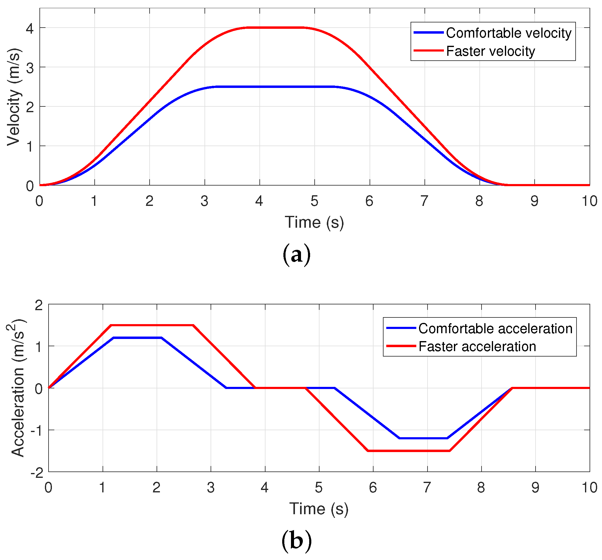
If the elevator runs at a rated speed as much as possible, it can shorten the traveling time and fully use the motor capacity. However, the acceleration is directly related to the system force, which can be perceived by the passengers in the car. When the speed or acceleration change is too large or frequent, it will affect passengers’ comfort. Hence, a general requirement is that the maximum value of starting acceleration and braking deceleration of the elevator car should not be greater than 1.5 m / s 2 .
Considering factors such as running noise, running time, motor power level, and ride comfort, we adopt an S-shaped speed profile as the target velocity trajectory of the elevator system. The mathematical expression of this profile with respect to running time, assuming as 10 s, is shown as follows:
v ( t ) = q t 2 0 t < 1.2 v ( t ) = 0.72 + 1.2 ( t 1.2 ) 1.2 t < 2.083 v ( t ) = 2.5 p ( 3.283 t ) 2 2.083 t < 3.283 v ( t ) = 2.5 3.283 t < 5.283 v ( t ) = 2.5 p ( 5.283 t ) 2 5.283 t < 6.483 v ( t ) = 1.78 1.2 ( t 6.483 ) 6.483 t < 7.366 v ( t ) = p ( 8.566 t ) 2 7.366 t < 8.566 v ( t ) = 0 8.566 t 10
where p is chosen as p = 0.5 for the acceleration in the start-up and braking sections to meet the requirement of comfort and rapidity. However, for the aim of testing the performance of the designed controller, we also employ an appropriately faster speed profile as the reference command:
v ( t ) = q t 2 0 t < 1.154 v ( t ) = 0.865 + 1.5 ( t 1.154 ) 1.154 t < 2.667 v ( t ) = 4 q ( 3.821 t ) 2 2.667 t < 3.821 v ( t ) = 4 3.821 t < 4.746 v ( t ) = 4 q ( 4.746 t ) 2 4.746 t < 5.899 v ( t ) = 3.135 1.5 ( t 5.899 ) 5.899 t < 7.412 v ( t ) = q ( 8.566 t ) 2 7.412 t < 8.566 v ( t ) = 0 8.566 t 10
where q = 0.65 . To visualize them, the above reference velocity profiles and the corresponding acceleration profiles are shown in Figure 2.

5.2. Analysis of Simulation Results

To make the simulation verification more realistic, a fractional-order sliding mode controller without an observer and a conventional PI-sliding mode controller (PISMC) are designed as benchmark controllers to be compared with the proposed control scheme.
The simulations are conducted over a uniform period of 10 s. Furthermore, the mean absolute errors (MAEs) and root-mean-square errors (RMSEs) under the effect of these controllers are calculated for a fair and comprehensive comparison. The definitions of MAE and RMSE are given as follows:
MAE = 1 m i = 1 m e i
RMSE = 1 m i = 1 m e i 2
where m is the number of error sampling points.
Case 1.
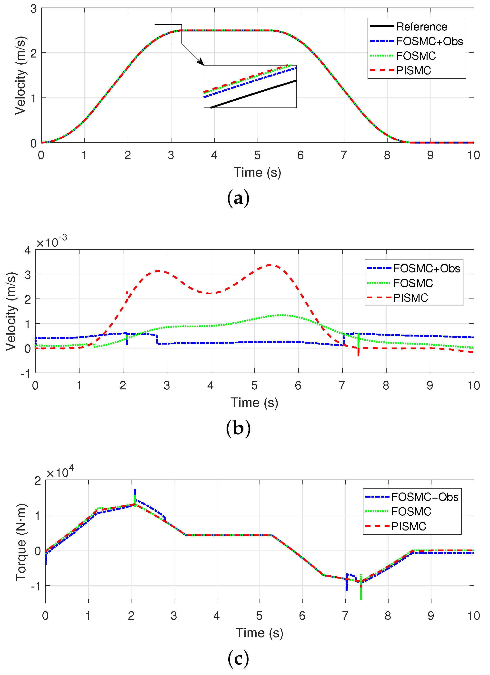
In this case, the elevator is assumed to be unloaded and running at a comfortable speed. Under this condition, the elevator is free from additional loads and stresses, which allows for testing the basic operating performance of the elevator, including starting, stopping, acceleration, deceleration, smoothness, and accuracy of the control system. The simulation results in this case are shown in Figure 3 and Figure 4.
Figure 3a shows the trajectory tracking profiles of the three controllers in Case 1. It can be seen that although the tracking performance of different algorithms varies, all of them can realize the basic requirements of trajectory tracking.
Figure 3b shows the tracking errors of different controllers in Case 1. We can see that the tracking errors of FOSMC + Obs and FOSMC are smaller, and the fluctuations of these errors are also smaller in the whole running process. However, the error of PISMC is larger, especially during the periods of starting and stopping. This indicates that the sliding mode controllers based on fractional-order calculus theory can make the elevator track the reference speed more accurately.
Figure 3c demonstrates the input torques, i.e., the control signals of the system. It can be seen that all the control inputs possess larger changes during the start and stop phases. The main reason is that more torques are needed to overcome the inertia and achieve the desired speed change in these two phases.
Figure 4 illustrates the MAEs and RMSEs of the three controllers in Case 1. It can be seen that FOSMC + Obs reduces 32.71% and 69.98% in MAE and 42.25% and 60.42% in RMSE compared with FOSMC and PISMC, respectively, which demonstrates that the designed FOSMC + Obs possesses excellent control performance.
Case 2.
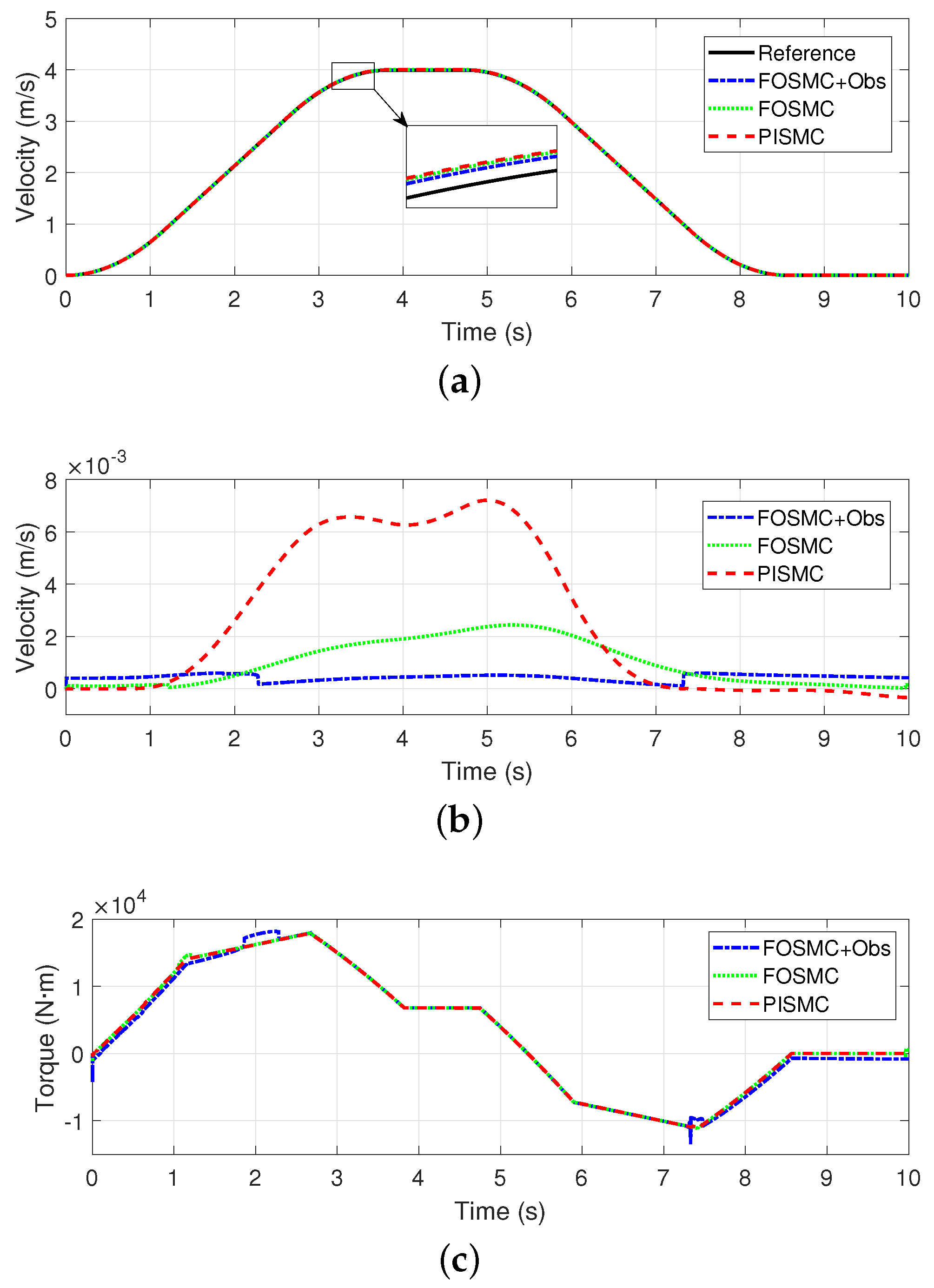
In this case, the elevator is set to operate at a comfortable speed with partial loads. Assuming that the elevator is loaded with five passengers, and each passenger weighs 65 kg, the elevator dynamics under this condition will be quite different from those in Case 1, which affects the acceleration, braking effort, and smoothness of the elevator to a large extent. Therefore, the designed controllers confront more serious challenges. The simulation results in this case are shown in Figure 5 and Figure 6.
From Figure 5a, it can be seen that the tracking curves of the three controllers can still follow the reference curve generally.
Figure 5b shows the tracking errors of all the controllers. We can see that the error of FOSMC + Obs remains the smallest, especially during the acceleration and deceleration phases. The error of FOSMC remains at a relatively low level. The error of PISMC is still the largest in this case, especially during the starting and stopping phases.
Figure 5c illustrates that all the control inputs perform larger variations during the starting and stopping phases. The PISMC possesses the smoothest control input, but its tracking accuracy is also the lowest. Considering the highest tracking precision of FOSMC + Obs, the small cost of slight fluctuations in its control input can be considered as worthy.
Figure 6 shows the MAE and RMSE of the three controllers in Case 2. It can be seen that FOSMC + Obs reduces 31.65% and 68.86% in MAE and 40.27% and 77.28% in RMSE compared with FOSMC and PISMC, respectively. The superiority of the proposed control scheme is further illustrated.
Case 3.
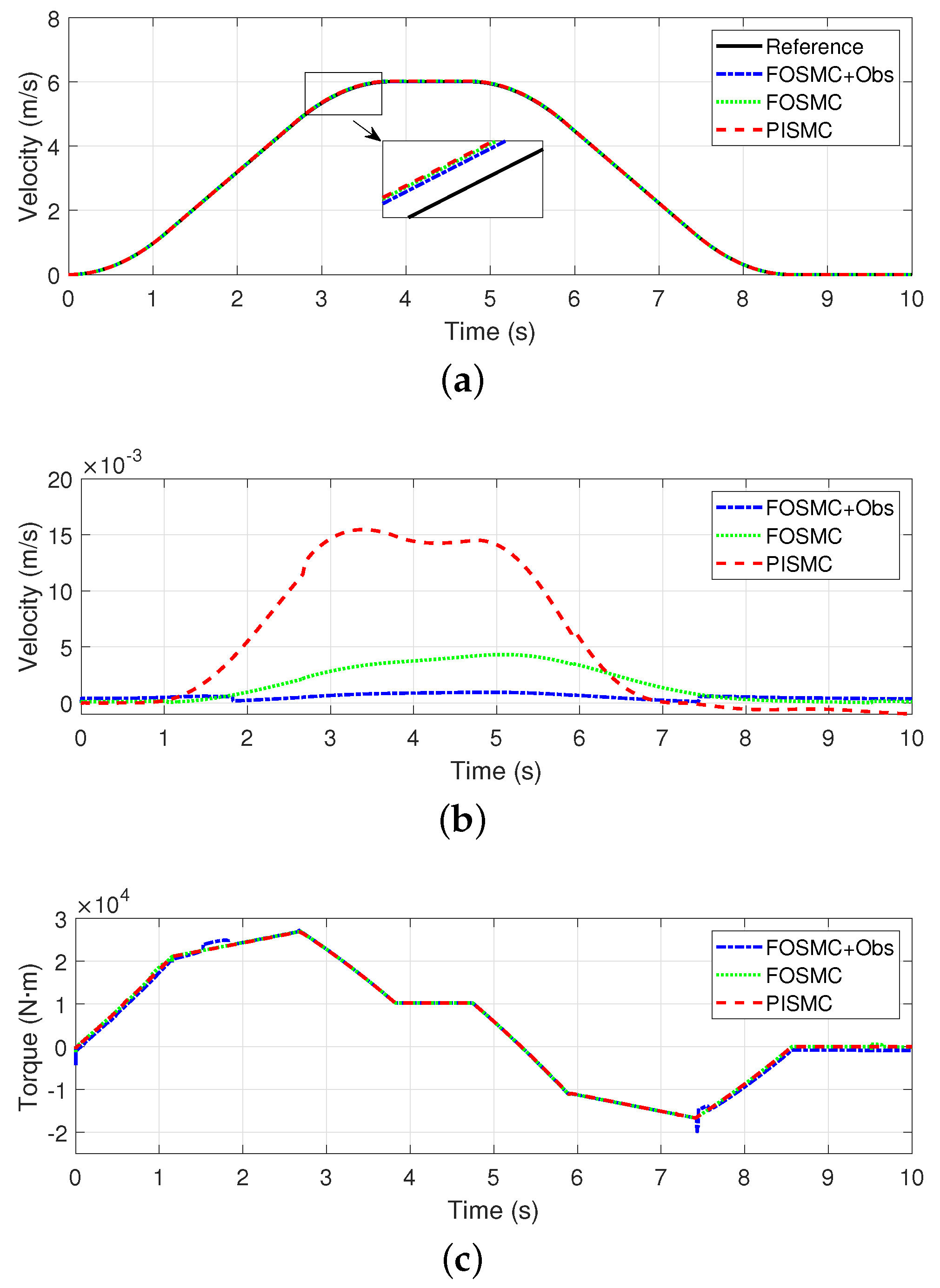
In this case, the elevator is set to operate at a relatively faster speed with partial loads (five passengers, and each passenger weighs 65 kg). The faster-speed operation will place higher demands on the dynamic response, safety, and ride comfort of the elevator system. In this case, special attention needs to be paid to the elevator’s starting speed, acceleration, and ability to control vibration and noise. The simulation results are shown in Figure 7 and Figure 8.
As can be seen from Figure 7, the tracking curves under the effect of three controllers can still follow the reference speed curve, but the performance difference is more evident compared with the previous two cases. The tracking error of FOSMC + Obs is still the smallest, especially in the acceleration and deceleration phases.
Figure 8 shows the MAE and RMSE of the three controllers in Case 3. It can be seen that FOSMC + Obs reduces 55.74% and 83.57% in MAE and 65.30% and 88.41% in RMSE compared with FOSMC and PISMC, respectively. Then, the superiority of the proposed control scheme is illustrated more comprehensively.
Case 4.
In this case, the elevator is set to operate at a high speed with a substantial load, simulating a condition with 20 passengers, each weighing 65 kg. This configuration aims to further validate the reliability of the elevator control algorithm under harsh conditions. The increased load creates substantial demands on the system, specifically regarding its ability to maintain stable and secure operations. Therefore, this case offers valuable insights into the elevator’s performance in managing heightened operational stress while sustaining smooth acceleration, deceleration, and ride quality. The simulation results are shown in Figure 9 and Figure 10.
Based on Figure 9, it is evident that the tracking curves for all three controllers continue to follow the reference speed curve. Even with the increased load and faster velocity, the system maintains good control performance. Notably, the tracking error for FOSMC + Obs remains the lowest, particularly during the acceleration and deceleration phases.
Figure 10 presents the MAE and RMSE of the three controllers in Case 4. It is evident that FOSMC + Obs achieves reductions of 67.36% and 89.99% in MAE, and 74.21% and 92.68% in RMSE, compared to FOSMC and PISMC, respectively. This more comprehensively demonstrates the advantages of the proposed control scheme.
In summary, FOSMC + Obs delivers the best performance across all three cases, as evidenced by the smallest tracking errors compared to the benchmark controllers. Furthermore, its consistent superiority across these cases confirms its robust capability in handling a variety of operating scenarios.

6. Conclusions

In this study, we focus on the design and analysis of motion control strategies for elevator systems based on disturbance observers and fractional-order fixed-time sliding mode control. By exploring the application of fractional-order calculus theory in motion control, a novel FASMO-based FOSMC approach is proposed to improve the motion performance of elevator systems. This approach not only considers and copes with the model uncertainties and external disturbances of the elevator system, but also ensures the ride comfort of elevator passengers via smooth control input. Through simulation validations, the advantages of the proposed control strategy in enhancing the speed profile tracking accuracy and anti-interference ability are comprehensively demonstrated.
Future research directions include further optimizing the controller design to improve the elevator system performance under complex operating conditions and exploring the potential of fractional-order control theory in more applications. These efforts are believed to provide new ideas and solutions for motion control applications and promote innovation in the corresponding field.

Author Contributions

Writing—original draft, Z.S.; methodology, Z.S. and H.L.; validation, H.L. and K.L.; data curation, K.L. and W.S.; software, W.S. and Y.J.; visualization, Y.J.; resource, B.C. All authors have read and agreed to the published version of the manuscript.

Funding

This research was funded by the Key Research and Development Program of Zhejiang Province (2023C01144), the National Natural Science Foundation of China (62473337, 62003305), and the Natural Science Foundation of Zhejiang Province (LQ21F030015).

Data Availability Statement

The data generated during the current study is available from the corresponding author upon reasonable request.

Conflicts of Interest

The authors declare that they have no known competing financial interests or personal relationships that could have appeared to influence the work reported in this paper.

References

  1. Ovaska, S.J. Electronics and information technology in high-range elevator systems. Mechatronics 1992, 2, 89–99. [Google Scholar] [CrossRef]
  2. Cho, M.; Lee, M. Modeling study on distributed control of elevators. J. Inst. Electr. Eng. 2007, 44, 35–40. [Google Scholar]
  3. Ladany, S.; Hersh, M. The design of an efficient elevator operating system. Eur. J. Oper. Res. 1995, 25, 251–270. [Google Scholar] [CrossRef]
  4. Wen, X. Study of elevator safety system problems and improvement programs. J. Korean Comput. Inf. Soc. 2020, 25, 221–230. [Google Scholar]
  5. Rui, W.; Luo, F.; Huang, X.; Li, P. New elevator energy feedback control system design based on fuzzy PID controller. In Proceedings of 2012 Power Engineering and Automation Conference, Wuhan, China, 18–20 September 2012; pp. 1–6. [Google Scholar]
  6. Li, C.; Cao, L.; Zhang, A. Application of neural network PID controller to elevator control system. In Proceedings of the 29th Chinese Control Conference, Beijing, China, 29–31 July 2010; pp. 71–74. [Google Scholar]
  7. Xu, X.; Wang, Q. Speed control of hydraulic elevator by using PID controller and self-tuning fuzzy PID controller. In Proceedings of the 2017 32nd Youth Academic Annual Conference of Chinese Association of Automation (YAC), Hefei, China, 19–21 May 2017; pp. 812–817. [Google Scholar]
  8. Wu, L.; Wang, Y.; Zhou, S.; Tan, W. Design of PID controller with incomplete derivation based on differential evolution algorithm. J. Syst. Eng. Electron. 2008, 19, 578–583. [Google Scholar]
  9. Rajaraman, K.; Nagaraja, S.K. An elevator speed-control system using squirrel-cage induction motors. IEEE Trans. Ind. Electron. 1984, IE-31, 164–167. [Google Scholar] [CrossRef]
  10. Yu, J.; Kim, S.; Lee, B.; Won, C.; Hur, J. Fuzzy-logic-based vector control scheme for permanent-magnet synchronous motors in elevator drive applications. IEEE Trans. Ind. Electron. 2007, 54, 2190–2200. [Google Scholar]
  11. Zhang, H.; Zhang, R.; He, Q.; Liu, L. Variable universe fuzzy control of high-speed elevator horizontal vibration based on firefly algorithm and backpropagation fuzzy neural network. IEEE Access 2021, 9, 57020–57032. [Google Scholar] [CrossRef]
  12. Man, Z.; Palaniswami, M. Robust tracking control for rigid robotic manipulators. IEEE Trans. Autom. Control 1994, 39, 154–159. [Google Scholar]
  13. Sun, Z.; Zheng, J.; Man, Z.; Wang, H. Robust control of a vehicle steer-by-wire system using adaptive sliding mode. IEEE Trans. Ind. Electron. 2016, 63, 2251–2262. [Google Scholar] [CrossRef]
  14. Sun, Z.; Zheng, J.; Man, Z.; Fu, M.; Lu, R. Nested adaptive super-twisting sliding mode control design for a vehicle steer-by-wire system. Mech. Syst. Signal Process. 2019, 122, 658–672. [Google Scholar] [CrossRef]
  15. Liu, Y.-C. Disturbance-Observer-Based Sliding-Mode Speed Control for Synchronous Reluctance Motor Drives via Generalized Super-Twisting Algorithm. Actuators 2024, 13, 233. [Google Scholar] [CrossRef]
  16. Sun, Z.; Xie, H.; Zheng, J.; Man, Z.; He, D. Path-following control of Mecanum-wheels omnidirectional mobile robots using nonsingular terminal sliding mode. Mech. Syst. Signal Process. 2021, 147, 107128. [Google Scholar] [CrossRef]
  17. Sun, Z.; Hu, S.; Xie, H.; Li, H.; Zheng, J.; Chen, B. Fuzzy adaptive recursive terminal sliding mode control for an agricultural omnidirectional mobile robot. Comput. Electr. Eng. 2023, 105, 108529. [Google Scholar] [CrossRef]
  18. Kavikumar, R.; Kaviarasan, B.; Lee, Y.G.; Kwon, O.M.; Sakthivel, R.; Choi, S.G. Robust dynamic sliding mode control design for interval type-2 fuzzy systems. Discret. Contin. Dyn. Syst.-Ser. S 2022, 15, 1839. [Google Scholar] [CrossRef]
  19. Yu, Z.; Li, J.; Xu, Y.; Zhang, Y.; Jiang, B.; Su, C.-Y. Reinforcement Learning-Based Fractional-Order Adaptive Fault-Tolerant Formation Control of Networked Fixed-Wing UAVs With Prescribed Performance. IEEE Trans. Neural Networks Learn. Syst. 2024, 35, 3365–3379. [Google Scholar] [CrossRef]
  20. Chaudhary, S.-K.; Kumar, N. Fractional order fast terminal sliding mode control scheme for tracking control of robot manipulators. ISA Trans. 2023, 142, 57–69. [Google Scholar] [CrossRef]
  21. Bruzzone, L.; Fanghella, P.; Basso, D. Application of the Half-Order Derivative to Impedance Control of the 3-PUU Parallel Robot. Actuators 2022, 11, 45. [Google Scholar] [CrossRef]
  22. Sun, G.; Ma, Z. Practical Tracking Control of Linear Motor With Adaptive Fractional Order Terminal Sliding Mode Control. IEEE/ASME Trans. Mechatronics 2017, 22, 2643–2653. [Google Scholar] [CrossRef]
  23. Zhang, X.; Li, J.; Ma, Z.; Chen, D.; Zhou, X. Lateral Trajectory Tracking of Self-Driving Vehicles Based on Sliding Mode and Fractional-Order Proportional-Integral-Derivative Control. Actuators 2024, 13, 7. [Google Scholar] [CrossRef]
  24. Fei, J.; Feng, Z. Fractional-order finite-time super-twisting sliding mode control of micro gyroscope based on double-loop fuzzy neural network. IEEE Trans. Syst. Man, Cybern. Syst. 2021, 51, 7692–7706. [Google Scholar] [CrossRef]
  25. Ma, Z.; Liu, Z.; Huang, P.; Kuang, Z. Adaptive fractional-order sliding mode control for admittance-based telerobotic system with optimized order and force estimation. IEEE Trans. Ind. Electron. 2022, 69, 5165–5174. [Google Scholar] [CrossRef]
  26. Chen, S.; Chiang, H.; Liu, T.; Chang, C. Precision motion control of permanent magnet linear synchronous motors using adaptive fuzzy fractional-order sliding-mode control. IEEE/ASME Trans. Mechatronics 2019, 24, 741–752. [Google Scholar] [CrossRef]
  27. Dokic, R.; Vladic, J.; Kljajin, M.; Jovanovic, V.; Markovic, G.; Karakasic, M. Dynamic modelling, experimental identification and computer simulations of non-stationary vibration in high-speed elevators. J. Mech. Eng. 2021, 67, 287–301. [Google Scholar]
  28. Moulay, E.; Léchappé, V.; Bernuau, E.; Plestan, F. Robust fixed-time stability: Application to sliding-mode control. IEEE Trans. Autom. Control 2022, 67, 1061–1066. [Google Scholar] [CrossRef]
  29. Kilbas, A.; Srivastava, H.; Trujillo, J. Fractional integrals and fractional derivatives. In Theory and Applications of Fractional Differential Equations, 1st ed.; Elsevier: Amsterdam, The Netherlands, 2006; pp. 69–133. [Google Scholar]
  30. Pudlubny, I. Fractional Differential Equations; Academic: Cambridge, MA, USA, 1999. [Google Scholar]
  31. Kuang, Z.; Sun, L.; Gao, H.; Tomizuka, M. Practical fractional-order variable-gain super twisting control with application to wafer stages of photolithography systems. IEEE/ASME Trans. Mechatronics 2022, 27, 214–224. [Google Scholar] [CrossRef]
  32. Polyakov, A. Nonlinear feedback design for fixed-time stabilization of linear control systems. IEEE Trans. Autom. Control 2012, 57, 2106–2110. [Google Scholar] [CrossRef]
  33. Tian, B.; Zuo, Z.; Yan, X.; Wang, H. A fixed-time output feedback control scheme for double integrator systems. Automatica 2017, 80, 17–24. [Google Scholar] [CrossRef]
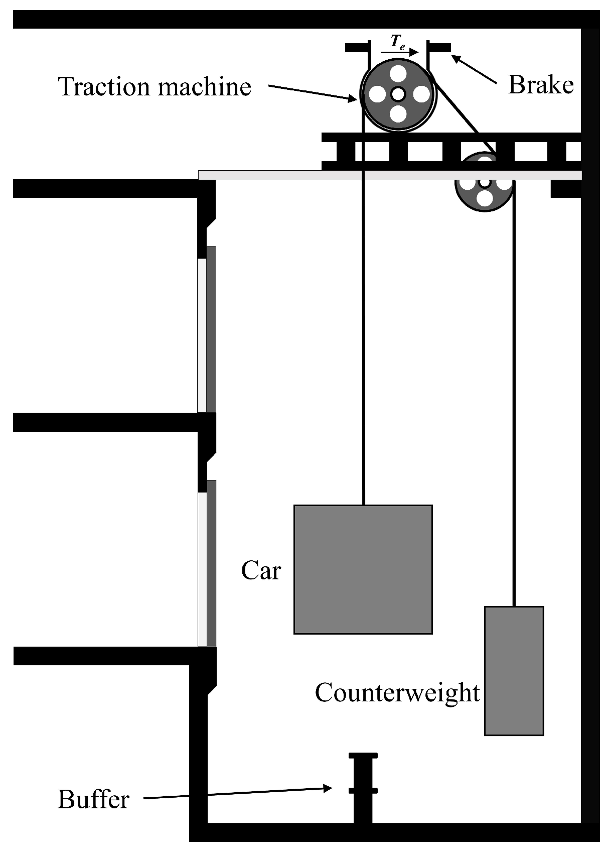
Figure 1. Schematic of elevator structure.
Actuators 13 00438 g001
Figure 2. Velocity and acceleration references of elevator system. (a) Velocity profiles; (b) acceleration profiles.
Actuators 13 00438 g002
Figure 3. Simulation results in Case 1. (a) Tracking profiles; (b) tracking errors; (c) control inputs.
Actuators 13 00438 g003
Figure 4. Comparison of MAE and RMSE in Case 1. (a) MAE; (b) RMSE.
Actuators 13 00438 g004
Figure 5. Simulation results in Case 2. (a) Tracking profiles; (b) tracking errors; (c) control inputs.
Actuators 13 00438 g005
Figure 6. Comparison of MAE and RMSE in Case 2. (a) MAE; (b) RMSE.
Actuators 13 00438 g006
Figure 7. Simulation results in Case 3. (a) Tracking profiles; (b) tracking errors; (c) control inputs.
Actuators 13 00438 g007
Figure 8. Comparison of MAE and RMSE in Case 3. (a) MAE; (b) RMSE.
Actuators 13 00438 g008
Figure 9. Simulation results in Case 4. (a) Tracking profiles; (b) tracking errors; (c) control inputs.
Actuators 13 00438 g009
Figure 10. Comparison of MAE and RMSE in Case 4. (a) MAE; (b) RMSE.
Actuators 13 00438 g010
Disclaimer/Publisher’s Note: The statements, opinions and data contained in all publications are solely those of the individual author(s) and contributor(s) and not of MDPI and/or the editor(s). MDPI and/or the editor(s) disclaim responsibility for any injury to people or property resulting from any ideas, methods, instructions or products referred to in the content.