Abstract
In this paper, the design of a driving mechanism for a heavy-duty collaborative robot (cobot) capable of lifting payloads up to 20 kg is presented. This study focuses on an articulated robot utilizing a water-based Electro-Hydraulic Actuator (EHA). The Denavit–Hartenberg (D–H) representation was employed to relate the rotational angles and the end-effector’s location, facilitating the design of the actuators. The maximum required torques for joints 2 and 3, responsible for lifting for 12 s, were calculated under quasi-static and dynamic loading conditions. The results showed that the maximum required torques were 126.67 Nm and 58.86 Nm for joint 2 and 3, respectively. The maximum torque for joint 2 occurs when the pitch links are fully extended, whereas the maximum torque for joint 3 occurs when the third link is parallel to the ground. The torques, due to the inertia and Coriolis dynamic terms, were also calculated and found to be lower than those required for the gravitational term. Various maneuvering scenarios, along with Ansys Motion simulation, were analyzed for the verification of the results. Based on the calculated maximum torques, the linear actuators of the EHA were designed. The heavy-duty cobot can be built with the developed actuator proposed in this paper. The total weight of the entire frame was measured to be 14.59 kg, resulting in a high Payload/Weight (P/W) ratio of 1.37. In conclusion, the robot was made lighter and can operate more efficiently, particularly for heavy loads up to 20 kg.
1. Introduction
A collaborative robot, which is commonly abbreviated as ‘cobot’, helps humans to make work safer and easier [1]. The main characteristic of cobots is that, unlike traditional industrial robots, they share a workspace with humans without safety fences. In the early 2000s, collaborative robots were referred to as “small and medium enterprise (SME) robots” due to their simplicity and ease of operation compared to industrial robots [2]. In 2016, the International Standard Organization established ‘Collaborative Robot’ (ISO/TS 15066, Robots and robotic devices–Collaborative robots [3]). In Korea, the national technical standard is ‘collaborative robot’ (KS B ISOTS15066, Robots and robotic devices–Collaborative robots [4]). Since the mid-2000s, Universal Robots (Odense, Denmark), one of the leading companies in the field, has pioneered the market with the release of UR3, and it has been widely used until now [5]. These cobots are utilized in a variety of fields. In manufacturing, they are used for assembly tasks [6]; in logistics and warehousing, for transporting and organizing goods [7]; in agriculture, for crop management and harvesting [8]; and in construction and public works, they are used to aid in work and improve safety [9].
Cobots have been developed to automate tasks, ensure safety, increase productivity, and improve the work environment [10]. If cobots are adopted to perform tasks in a collaborative manner, the robot can efficiently handle repetitive and tedious tasks to improve productivity, while the human worker can focus on complex and creative tasks to foster innovation. At the same time, the introduction of cobots helps to increase safety. Robots can reduce worker fatigue by taking over dangerous or repetitive tasks, and various safety devices can detect collisions with humans to ensure worker safety, reducing the risk of accidents and injuries in the workplace. It also makes the work environment more human-friendly by sharing the work area with workers without the need for cumbersome safety fences. By employing cobots, the workspace can be optimized by easy relocation of robots to minimize the travel distance and labor. This contributes to a better working environment by increasing worker comfort and efficiency.
In parcel delivery logistics, construction sites, and production lines, people repeatedly lift and lower objects weighing more than 20 kg, such as a pack of rice or a bundle of water bottles, on a daily basis [11]. In the case of household waste, moving this 20 kg weight once or twice can be done with no such great difficulty. However, repeating this job many times is not only tedious but also dangerous. In addition, if the waste is bundled or packed, such as plastic bottles, the moment of inertia is high, making it unstable. Previous research on musculoskeletal disorders shows that heavy lifting and repetitive tasks cause occupational musculoskeletal disorders, and they are steadily increasing [11,12]. Therefore, if collaborative robots are used for the aforementioned tasks, they can improve working conditions and prevent accidents such as worker fatigue or injuries.
As shown in Table 1, the payloads of commercially available well-known cobots used in the workplace vary widely, which limits the ability to deploy the appropriate robot in the field for handling heavy objects, such as in parcel logistics. The ratio of payload to robot weight (P/W) shows that cobots in the market generally have this P/W ratio of less than one, despite having a payload of up to 20 kg, making it difficult to freely deploy and operate them in the field. In fact, most cobots use rotary motor drives, which have a payload of less than 15 kg due to the mechanical limitations of the drive unit, and there is an inherent risk of using a drive unit that is larger than the payload. In addition, if we look at the cobots with a payload of 20 kg, Universal Robots UR20, ABB (Zurich, Switzerland) GoFa, Rethink Robotics (Boston, MA, USA) Sawyer, and KUKA (Augsburg, Bavaria, Germany) iiwa, which are widely used in the field, the robots themselves are not optimized for configuration and operation due to their daunting volume and heavy weight.

Table 1.
Examples of weight specifications from commercial collaborative robots.
In this paper, we design a linear actuator as a driving mechanism for a heavy-duty cobot handling 20 kg payloads having a high P/W ratio. To innovate in terms of the P/W ratio, we consider an electro-hydraulic actuator (EHA) [13], which is the linear actuator shown in Figure 1. The EHA is unlike the large and complicated conventional hydraulic system, as it consists of an electric motor, pump, tubing (or piping), and an actuator [14]. In addition, unlike conventional hydraulics, the EHA system is independently configured, so the fluid circuit is shorter, and there is no need for accessories such as expansion tanks and valves, and so the nonlinearities of the hydraulic circuit are relatively less. As a result, the actuator can be freely installed, making the robot lighter and reducing the volume. It also has a good power-to-weight ratio, which is advantageous in systems that require high power. Commercial EHAs use a mineral oil-based fluid as the working fluid, as do most hydraulic systems. Given the nature of cobots working in close proximity to humans, designing a cobot with a device such as a water-based EHA [14] would allow for the high P/W ratio while still meeting the design requirements of a safe and environmentally friendly actuator. In addition, if off-the-self (standardized) EHAs are available in the market, it is possible to build a low-cost cobot by applying multiple lightweight and simple EHAs to a single linear actuator according to the operating load level [15]. To this end, this paper presents the basic actuator design procedure for water-based EHAs and verification results by simulation. This paper primarily addresses the design procedure and its application to the high P/W cobot, which will enable the heavy-duty usage. Instead of focusing on finding physical phenomenon, the design is based on the sizing of the EHA, and the design verification is conducted.
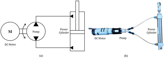
Figure 1.
Electro-Hydraulic Actuator (EHA). (a) Hydraulic circuit diagram; (b) EHA unit.
This paper is organized as follows. Section 2 surveys the literature related to linear drive mechanisms and reviews their applicability, advantages and disadvantages. Section 3 describes the background and theory for the actuator design. Section 5 presents the dynamic simulation to verify the calculation results given in Section 4. The linear actuator design is presented in Section 6, and Section 7 discusses the calculated results and design derived in Section 3, Section 4 and Section 5. Finally, the concluding remarks of this study are given in the Section 8.
2. Related Technologies
On the shop floor, equipment such as forklifts, stackers, hoists, and cranes are used for heavy-duty operations [16]. Forklifts and stackers have the advantage of requiring only one operator for transportation tasks, but the heavy weight of the vehicle and the lack of forward visibility during loading can make them dangerous. Hoists and cranes are both capable of lifting heavy loads, but they have the disadvantage of being very large in size and heavy in weight. Therefore, when considering cobots with linear drive, it is necessary to apply a linear actuator that can lower the weight and increase the payload to compensate for the problems of existing technologies when working with heavy loads.
Among conventional linear actuators, linear motors are directly driven without the need for auxiliary devices such as gears or cranks. As a result, they have good response characteristics, low kinetic energy losses due to backlash, friction, etc., and are free of noise and vibration. In addition, the direct drive method reduces the nonlinear effects of contact and has a simple structure. However, it is relatively expensive, and because it is directly driven without auxiliary devices, it requires careful maneuvering for precise control needs and so it may not be appropriate for rough heavy-duty jobs.
Ball screws have high mechanical efficiency and excellent torque transmission characteristics. Their low cost and the continuous development of production technology allow them to meet the required precision in the nanometer range. However, the positioning accuracy of ball screws is basically determined by the manufacturing precision, and the maximum travel length is limited.
A rack and pinion is a linear actuator that consists of a rack that works to convert rotary motion into linear motion and a pinion that engages it. It is inexpensive and easy to implement for long travel distances. The travel distance is limited by the length of the rack, but rack sections can be connected end-to-end to increase the distance. However, the gears engage, causing vibration, noise, and poor steering characteristics. The rack must be kept clean and, in high-speed environments, lubricants can contaminate the environment. They also require fewer components than systems with balls crews, which can reduce installation time. On the other hand, for high-precision applications, they have a demanding installation procedure that requires careful attention in detail, such as the installation gap between components, which requires expensive components.
Hydraulic actuators provide linear drive by changing the pressure in a hydraulic cylinder. This makes it a suitable actuator to increase the P/W ratio. For this reason, EHAs are used to control the attitude of an aircraft or in actuators that move robot legs [17,18]. Based on experiments with EHA actuators [15], a large linear force can be produced with a relatively small DC motor. Compared to conventional hydraulic systems, EHA [12], as shown in Figure 1b, is simpler to construct and has a smaller volume. Therefore, EHA can be applied to increase the payload size relative to the total weight of the robot.
3. Robot Configuration and Torque Calculation
The robot configuration in this design study is a Yaw Pitch Pitch (YPP) articulated robot [8], which is the most common type of existing collaborative robots. The robot testbed for the driving mechanism design is shown in Figure 2, where the first axis is yaw rotation, and the second and third axes are pitch rotation joints. Depending on the application of the robot, the range of motion of the three axes may be limited. In this study, the first axis has been set as a range of 360° about the axis, the second axis has a range of 30° to 80° about the axis, and the third axis has a range of −90° to −50° about the axis. Axes 2 and 3 need to be load-bearing, so this is where we will install the EHA linear actuator here. The axis 1 is a yawing motion and is not considered for this design study. The cylinder 2 for the axis 2 is installed 70 mm away in parallel with the link 1 to push the link 2, and the cylinder 3 is installed to push the link 3 with 20° difference from the joint 3. The point at which the cylinder pushes off link 3 is 115 mm away from the joint 3.
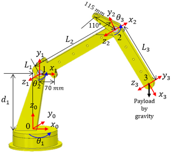
Figure 2.
Robot testbed with 3 degrees of freedom coordinate system for the mechanism design.
At each link of the robot, the coordinate system for each axis of rotation relative to the position is defined as shown in Figure 2. The Denavit–Hartenberg (D–H) representation of the rotation-translation relationship between the global 0 coordinate system and the 1 through 3 coordinate systems of each rotation axis is shown in Table 2. In the mathematical representation of D–H, trigonometric functions are abbreviated to denote cos as c and sin as s, and only the numbers for each axis are shown. The consecutive numbers represent the sum of the two angles, e.g., c12 means cos (θ1 + θ2).
Table 2.
Denavit–Hartenberg Expression.
The overall matrix that transforms the position of the manipulator end effector’s 3rd axis relative to the global coordinate system is obtained as the product of the transformation matrices for each joint and is derived as shown in Equation (1).
The Jacobian in Equation (2) shows the relationship between the velocity in joint space coordinates and the velocity in Cartesian coordinates (★—omitted element). Using this equation, the torque required at each joint to lift a given payload in quasi-static conditions can be calculated using Equation (3).
Here, the demand load is W in a vector form, since a linear force must be generated to lift the payload m defined based on the 0 axis coordinate system, the vector is equal to Equation (4).
Therefore, the torque required on each axis for a static load is equal to Equation (5).
For Equations (1)–(5), the torque can be calculated corresponding to a given in a static or quasi-static state, but for a robot in a dynamic state, the value of the torque may vary depending on its velocity and acceleration. Therefore, the dynamics equation in Equation (6) should be considered. The weight of the link (1~2 kg) is relatively small compared to the size of the payload considered in this paper, which is 20 kg, so link masses are ignored in this pilot study.
where
and
The respective linear force vectors for the rotation of the 2nd and 3rd shaft to drive the required torque, calculated based on Equations (5) and (6), and the power cylinder pressure vector to produce these linear forces are obtained as shown in Equation (7), taking into account the rotation radius r about the joint from the cylinder rod.
The design of a linear actuator is based on the maximum pressure. Since τ and P are linearly related, the linear actuator at each joint is designed by finding the corresponding maximum torque and converting it to pressure for the sizing of the actuators.
4. Torque-Pressure Calculation Results
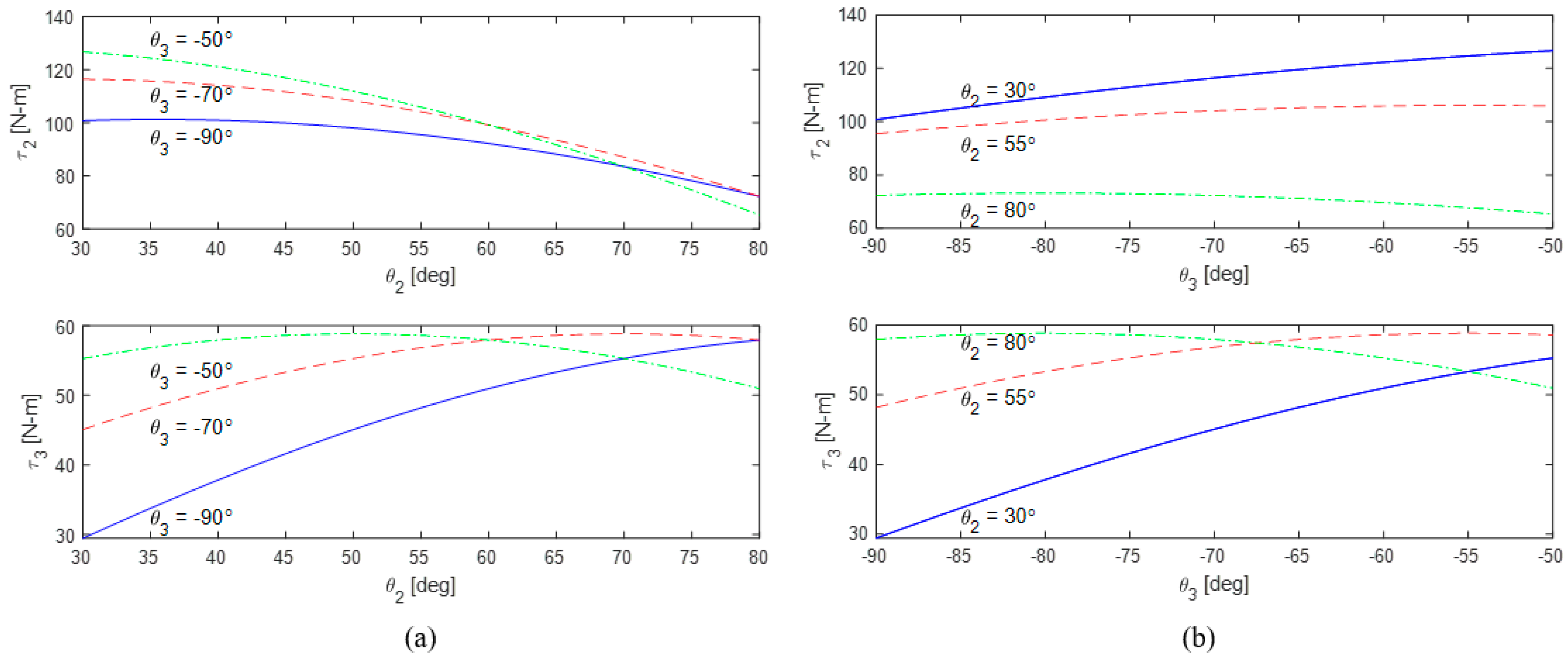
The torque calculation results by Equation (5) on the 2nd and 3rd axes are shown in Figure 3. Each figure (a and b) shows the torque calculation results when the relative degrees of freedom of the two axes are fixed and the corresponding axis degrees of freedom are viewed as variables.
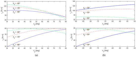
Figure 3.
Calculation results for the required τ2 and τ3 with respect to (a) θ2 and (b) θ3.
Figure 3a shows the calculation results for the three cases of −50°, −70°, and −90° for the 2nd axis rotation angle θ2 as a variable, and −50°, −70°, and −90° for the 3rd axis rotation angle θ3. The required torque 2 τ2 is found to be larger for smaller θ2 values in all cases for the same θ3, and so the smaller θ2 is, the larger τ2 is required. There is an exponential decrease in the required torque 2 with similar increases for the same θ3 angle. The bottom of the same figure shows the variation of torque 3. Torque 3 has a maximum value at the point where the sum of θ2 and θ3 is 0°, and torque 3 becomes smaller as the absolute difference between the θ2 and θ3 values increases. As shown in the figure, the maximum required torque 3 occurs at 80°, which is the maximum of the operating range as −90°, the sum cannot be 0° not being able to take 90° for θ2 (because θ2 = 90° is outside the operating range).
Figure 3b shows the results of a similar calculation for the 3rd axis rotation angle as a variable for three cases where the 2nd axis rotation angles are 30°, 55°, and 80°. This figure shows the same results, but from a different perspective. As seen earlier, the larger the value of θ3 for the same θ2, the larger τ2 required. The required τ2 decreases with increasing values of θ2, but for θ2 = 80°, this trend does not occur; rather, for larger values of θ3, the torque values remain similar or decreasing. For τ3, a similar shape is obtained for θ3 as well. The maximum torque calculation can also be obtained using the following differential equation:
Based on Equation (8), the maximum torques for 2 and 3, where θ3 is fixed and θ2 is variable, the maximum required τ2 and τ3 are the following, respectively:
If one rotation angle is fixed and the other is variable, the maximum torques 2 and 3 are shown in Equations (10) and (11). The results in Figure 3 show that torque 2 tends to be larger for smaller values. The maximum τ2 occurs at θ2 = 21.8° and θ3 = −50°, according to Equation (10). But this is outside the operating range, and the inverse tangent function is monotonically decreasing in that region, so τ2 is maximized at θ2 = 30°. The maximum torque required is calculated to be 126.67 Nm for τ2 at θ2 = 30° and θ3 = −50°, and 58.86 Nm for τ3 at θ2 = −θ3. The maximum required torque for each axis is summarized in Table 3.
Table 3.
Maximum required torque for each axis.
5. Dynamic Simulation for Verification
The required torque for the pitch joints in the earlier section was verified by using the commercial dynamics program, Ansys Motion 2023 R1 (Canonsburg, PA, USA), as shown in Figure 4. The material of the links was set to AL6061 and the payload of 20 kg was set. Figure 4b is the torque value by angle required for θ2, and Figure 4c is the torque value by angle required for θ3. When the torque results from Section 3 can be compared by the values from the computational analysis, it can be seen that the type of graph leads to a similar form, and the maximum torque values are shown and compared in Table 3. The required torques under various payloads were measured in the simulation, and the errors are 8.73% and 3.92% for the torque 2 and 3, respectively. These errors were mainly caused by the weight of the link itself (~1 kg per link) in the earlier calculations and the assumption that the turning radius is constant in the theoretical equations.
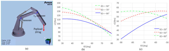
Figure 4.
(a) Numerical analysis prepocessing; (b,c) τ2 and τ3 Ansys measurements with respect to (b) θ2 and (c) θ3.
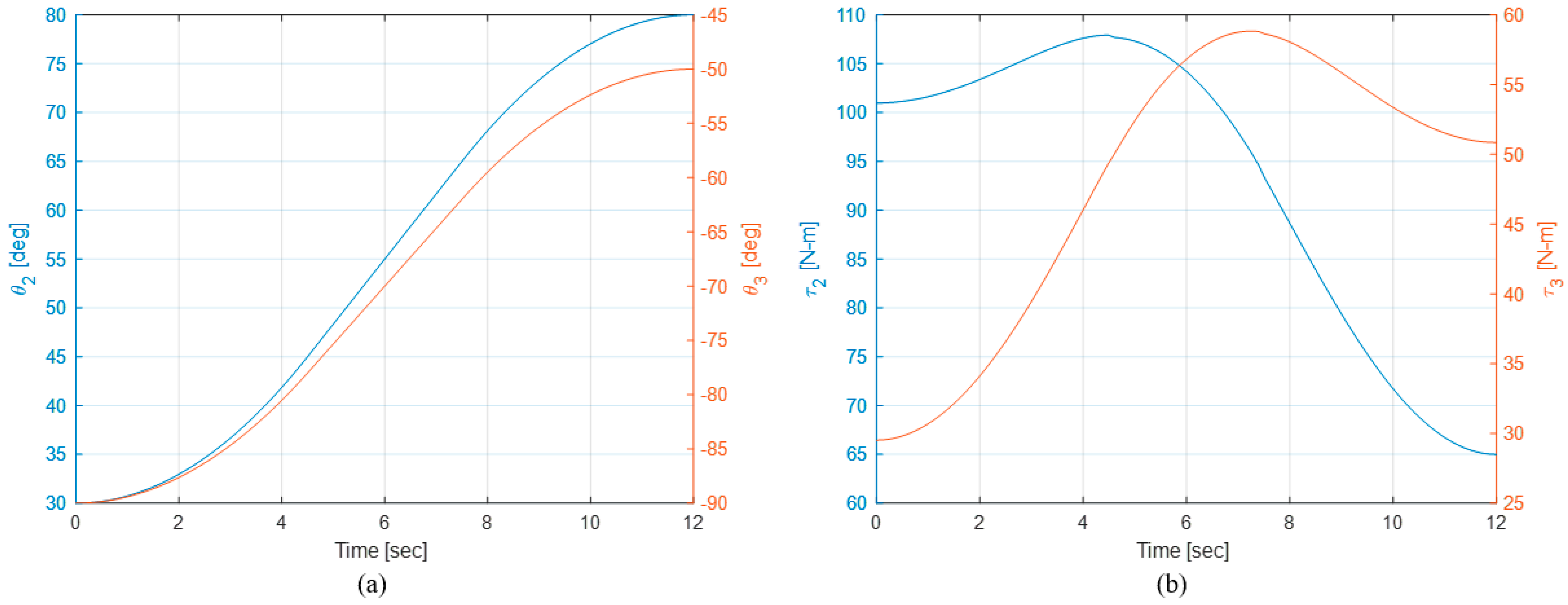
The Ansys simulation could yield the calculation results for only one set of simulation conditions such as the operation time duration. To assess the effectiveness of the dynamic loading more efficiently, the dynamic relation in Equation (6) with path planning is considered. In the previous study [19], the end-to-end stroke time of the cylinder was 12 s, during which time the links are assumed to be traveled by the Linear Segments with Parabolic Blends (LSPB) [20]. The acceleration a and the velocity V, which subscript represent the joint number, are given by Equations (12)–(15). Based on the planning scheme, a spline path was planned as shown in Figure 5a. In this path plan, the acceleration and deceleration periods are each planned to be 37.5% of the total travel time. If the acceleration periods are shorter than the above 37.5%, the constant velocity will be lower while they will be more accelerated. Conversely, planning longer than 37.5% will result in a higher constant speed and lower acceleration.
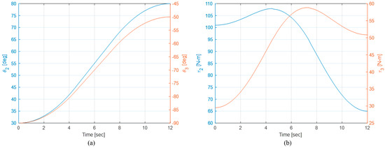
Figure 5.
(a) Path planning for cylinder end-point movement (LSPB); (b) time-torque for load movement from low to high position.
As shown in Figure 5b, where the load is raised from the lower end to the peak, the velocity and acceleration were not excessive, so the torque required was mainly dominated by the gravity. The point in the movement where τ3 requires the maximum torque of 58 Nm is at about 7.4 s when link 3 is leveled. However, there is no condition such that both links 2 and 3 are fully extended. Therefore, the maximum required torque of τ2 during movement is 108 Nm at about 4.2 s, which is less than the maximum torque of 126.67 Nm as shown earlier. According to the above dynamics scenario, the required torque only for the inertial and Coriolis forces was calculated to be no more than 0.5 Nm, which is small compared to the torque due to the gravity.
6. Linear Actuator Design
As stated in earlier sections, according to the given loading scenario in Section 4, the maximum torque of the static load calculated earlier can be used for the design of the linear actuator. The maximum internal pressure of the pump and the rotation radius about the axes of the links to the linear actuator r are taken into account and calculated by Equation (16). The linear forces can be obtained from the pump pressure P and the cross-sectional area of the power cylinder as the linear actuator A, and thus A for each linear actuator is determined by r and τ. The rotation radius is 70 mm for joint 2 and 115 × cos 20° mm for joint 3, as shown in Figure 3. Assuming that a swash plate-type axial piston pump with water as the working fluid with a maximum pressure of P = 1.9 MPa is used [12], then
Based on the calculations, the required diameters of the power cylinders for joints 2 and 3 are 34.8 mm and 17.5 mm from 952.4 mm2 and 286.7 mm2, respectively. Considering the calculated diameters of the cylinders, the CM2E model from SMC [21] was selected. Considering the neglection of the link weights with some capacity margin, cylinder 2 (joint 2) is designed with an inner diameter of Ø40 and a stroke length of 75 mm, and cylinder 3 is designed with an inner diameter of Ø20 and a stroke length of 75 mm. The model name of the motor applied to EHA is IG-32GM, with rated voltage DC 24V, rated torque Max. 12 kg-cm, size Ø36.3 × L 57.4 mm, shaft size Ø6 mm D-cut 0.5 mm. The selected gear reduction ratio is 1/5, which is generally lower than that of a typical rotary motor setting of robots.
As mentioned earlier, the robot frame material was selected as AL6061, and the volume of water (about ~100 mL for each EHA circuit) is negligible compared to the weight of the robot frame, so we only consider the weight of the cylinder additionally for the total weight. It is calculated as 14.59 kg, and this gives a P/W ratio of 1.37. The result of P/W ratio of 1.37 excludes the end effector, and the ratio can be further lowered by adding accessories, but it can be presented as a baseline value for the design. Of course, the amount of available payload can vary depending on the maximum motion length of the robot. The motion length in this study was based on a typical collaborative robot size of L2 + L3 = 720 mm, which is smaller than the 850 mm of the iiwa 14 R820. The motor-pump of the EHA will be installed on the robot base and connected to the cylinder by a tube, so that the pressure of the fluid generated by the EHA can rotate each link around the joint.
7. Discussion
Figure 6 shows the robot pose that the maximum torque is required for each joint. Figure 6a is the moment when τ2 is maximized. As τ2 is the greatest at the longest radius of rotation and the two pitch links are at their longest extension as shown in Figure 6a, it is obvious that this pose requires the maximum torque. However, τ3 cannot be maximized at the same time as τ2, because the third link cannot be horizontal due to the operating range of the 3rd axis angle (θ2 ≤ −50°). In Figure 6b, τ3 is at its maximum. As in the previous case, the torque is at its maximum when the force vector of gravity and the minimum distance from the axis of rotation (perpendicular vector) are the longest. Therefore, as mentioned earlier, when the last link is parallel to the ground and the sum of two joint angles becomes zero, τ3 reaches the maximum value and the results in earlier sections can be confirmed. As mentioned earlier, τ3 is maximized for a range of θ3 = −80° to −50°, and τ3 is maximized for all cases where the sum of θ2 and θ3 is zero. An example is shown in Figure 6b for this case where θ3 is −50°.
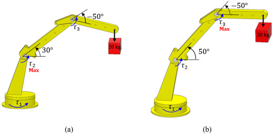
Figure 6.
(a) Maximum torque pose for τ2; (b) Maximum torque pose for τ3.
The maximum torque in both joints was found to be over 100 Nm. Of course, a state-of-the-art rotary motor with a high-ratio reduction gear set can handle such amount torque with the motor weight of 1–2 kg. But a general purpose 100 Nm servo motor, for example shown in [22], can be over 10 cm long on one side and can weigh over 50 kg. Basically, in order to install such a motor on two axes, the link must be designed to be even heavier, which contrasts with the roughly 0.5 kg motor used in the EHA presented in this study.
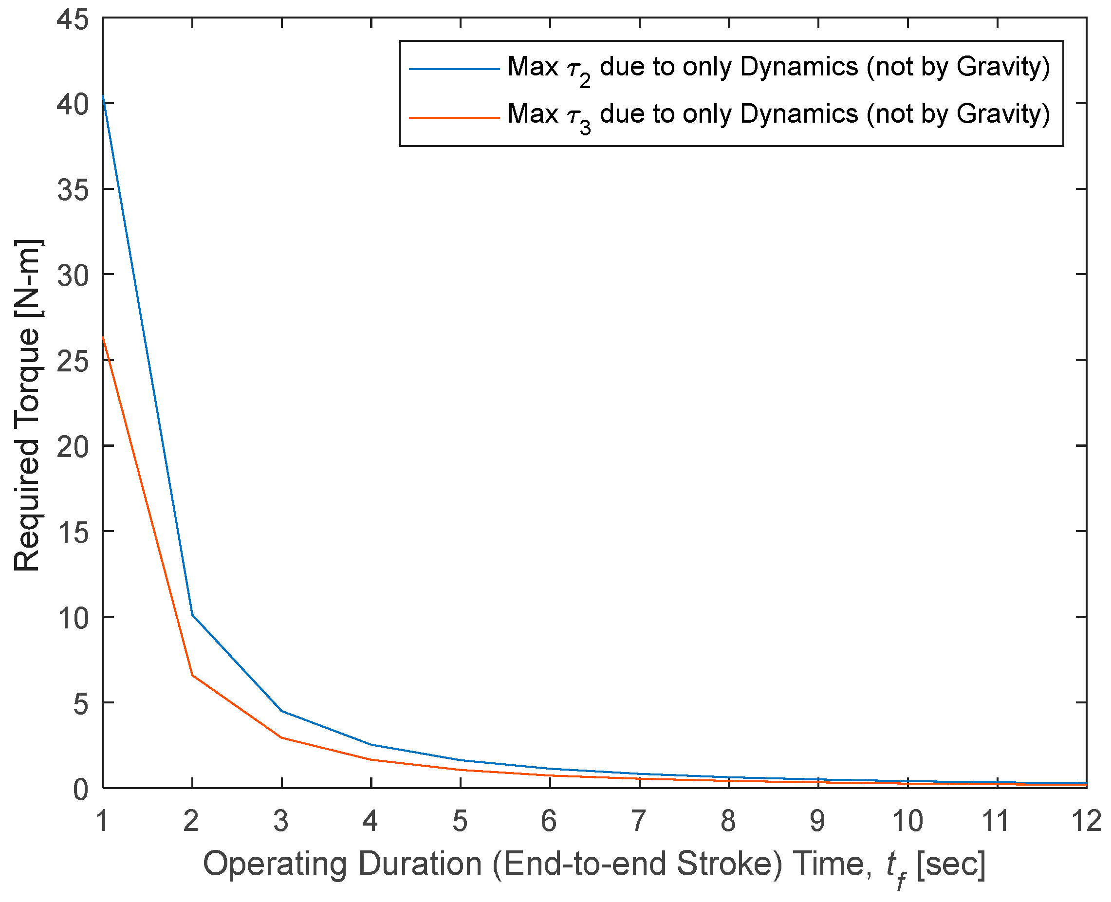
Since the calculation results were simulated from the previous study [20] in the prototype phase, the operating duration for traveling from the end to the top of the power cylinder could be slightly longer, the torques could be assessed slightly less than actual values. If the time duration becomes shorter, the dynamic terms can be dominant. As the motion time decreases, the velocity and acceleration also increase, so does the magnitude of the torque required by the dynamics terms. Therefore, the time duration of one stroke was varied, and required torques for dynamics terms except the gravity were assessed. Based on the same form of path planning, the magnitude of the maximum torque required by the dynamics terms, excluding the gravity term (g = 0 m/s2), is shown in Figure 7.
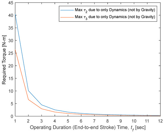
Figure 7.
Torque for various operational durations only required by dynamic terms excluding the gravity effect.
In Figure 7, the magnitude of the dynamics required torque increases exponentially as the motion time decreases from 12 s to 1 s. At the half the actuation time of the developed actuator, 6 s, the maximum torque required is only 1.24 Nm for τ2 and 0.84 Nm for τ3. If the travel time to the target should be less than 1 s, the torques (except the gravity effect) would be approaching 40 Nm (not an amount to be ignored), and the actuator would need to be redesigned fully with the dynamic equations. The short operation time requires higher pressure and flow rate by the swash-plate pump in the EHA system, but the slower response time is a typical drawback of the hydraulic systems relative to the fully electric components.
The effects of the remaining dynamics terms, other than gravity as discussed earlier, may seem small relative to the gravity term (due to the 20 kg targeted in this study and the relative slow motion). However, if a smaller payload were to be operated, the magnitude of the torque required by the dynamics terms would be more significant and would require further dynamics analysis.
8. Conclusions
In this paper, we proposed the design of EHA power cylinders as linear actuators for a heavy-duty cobot. The structure of the robot is a general articulated type and size. The actuator is an EHA linear driving mechanism that can handle a high payload by a low robot weight. Currently, most commercial cobots have a payload of 20 kg or less, which is a low payload compared to their weights, yielding a low P/W ratio of less than 1. In the design of this study, we proposed a cobot with a high P/W ratio of 1.37, which can handle a payload of 20 kg by applying an EHA drive method with water-based small EHAs that do not pollute the environment where it operates with humans.
For this purpose, static and dynamic load calculations were performed by the gravity from a 20 kg payload. As a result, the maximum required torque for the static load was calculated to be 127 Nm for the 2nd axis and 59 Nm for the 3rd axis. Based on the derived dynamics model, the previously calculated maximum required torque was analyzed. The results showed that the torque required by the dynamics, except for the gravity term, can be ignored for a 12 s movement as in the quasi-static design study. As a result, we were able to design a robot actuator using the static load calculations and design a linear drive power-cylinder with an inner diameter of Ø40 and a stroke length of 75 mm on the second axis and an inner diameter of Ø20 and a stroke length of 75 mm on the third axis.
The heavy-duty collaborative robot proposed in this study can handle heavy loads and operate more easily and efficiently with a lighter robot weight. This capability has been enabled by utilizing the EHA technology. In addition, the swash-plate pump in the EHA employs water as the working fluid, and so it can work with humans in a clean condition. The heavy-duty cobot equipped with EHAs can be used in delivery/logistics tasks, such as handling 20 kg worth of goods or manufacturing processing sites that handle heavy weights, and can effectively assist human workers. To this end, further research and development is needed to upgrade this heavy-duty robot mechanism up to the commercial level. In this study, only the weight of the load was considered to obtain early-stage design data. In future work, detailed analysis should be conducted to reflect accurate physical properties. For this purpose, dynamic simulations more in various scenarios will be conducted, followed by experimental studies to improve the EHA driving mechanism. Since safe operations of the robot must be guaranteed, condition monitoring and EHA performance control will be followed.
Author Contributions
Conceptualization and methodology development, H.-G.S.; validation, D.-W.L.; writing—original draft preparation, H.-G.S. and D.-W.L.; writing—review and editing, D.-W.L.; project administration, D.-W.L. All authors have read and agreed to the published version of the manuscript.
Funding
This work was supported by the National Research Foundation of Korea (NRF) grant funded by the Korea government (MSIT) (No. 2022R1G1A1005796).
Data Availability Statement
The data presented in this study are available on request from the corresponding author.
Acknowledgments
The authors thank the Korea government (MSIT) for the National Research Foundation of Korea (NRF) grant (No. 2022R1G1A1005796). Moreover, the authors express their gratitude to Ji-Won Kang for her invaluable contributions to the initial stages of literature preparation and calculations, and to Jung-Bae Ji for his role in preparing the ANSYS simulations.
Conflicts of Interest
Author Ha-Gwon Song was employed by the company ALUX Co., Ltd. The remaining authors declare that the research was conducted in the absence of any commercial or financial relationships that could be construed as a potential conflict of interest.
References
- Kragic, D.; Gustafson, J.; Karaoguz, H.; Jensfelt, P.; Pellegrini, N. Interactive, Collaborative Robots: Challenges and Opportunities. In Proceedings of the 27th International Joint Conference on Artificial Intelligence (IJCAI), Stockholm, Sweden, 13–19 July 2018. [Google Scholar]
- Pieskä, S.; Kaarela, J.; Saukko, O. Towards Easier Human-Robot Interaction to Help Inexperienced Operators in SMEs. In Proceedings of the 2012 IEEE 3rd International Conference on Cognitive Infocommunications (CogInfoCom), Kosice, Slovakia, 2–5 December 2012; pp. 333–338. [Google Scholar]
- ISO/TS 15066; Robots and Robotic Devices—Collaborative Robots. International Organization for Standardization: Geneva, Switzerland, 2016.
- KS B ISOTS15066; Robots and Robotic Devices–Collaborative Robots. Korean Standards Association: Seoul, Republic of Korea, 2017.
- Knudsen, M.; Kaivo-Oja, J. Collaborative Robots: Frontiers of Current Literature. J. Intell. Syst. Theory Appl. 2022, 3, 13–20. [Google Scholar] [CrossRef]
- Yu, H.J.; Kim, H.B. Cobot for Manufacturing. KISTEP Technol. Trends Brief 2020, 9, 1–5. [Google Scholar]
- Aleotti, J.; Baldassarri, A.; Bonfè, M.; Carricato, M.; Chiaravalli, D.; Di Leva, R.; Fantuzzi, C.; Farsoni, S.; Innero, G.; Rizzini, D.L.; et al. Toward Future Automatic Warehouses: An Autonomous Depalletizing System Based on Mobile Manipulation and 3D Perception. Appl. Sci. 2021, 11, 5959. [Google Scholar] [CrossRef]
- Grobbelaar, W.; Verma, A.; Shukla, V.K. Analyzing Human Robotic Interaction in the Food Industry. J. Phys. Conf. Ser. 2021, 1714, 012032. [Google Scholar] [CrossRef]
- Kim, T.H.; Lim, H.S.; Cho, S.J. Current Status and Prospects of Robot-Based Construction Automation Technology Development. Constr. Eng. Manag. 2021, 22, 9–14. [Google Scholar]
- Taesi, C.; Aggogeri, F.; Pellegrini, N. COBOT Applications—Recent Advances and Challenges. Robotics 2023, 12, 79. [Google Scholar] [CrossRef]
- Kim, H.J.; Jeong, W.C. Symptom Prevalence and Primary Intervention of Work-Related Musculoskeletal Disorders and Their Related Factors Among Manufacturing Workers. Ann. Occup. Environ. Med. 2005, 17, 116–128. [Google Scholar] [CrossRef]
- Kim, K.S.; Park, J.K.; Kim, D.S. Status and Characteristics of Occurrence of Work-Related Musculoskeletal Disorders. J. Ergon. Soc. Korea 2010, 29, 405–422. [Google Scholar] [CrossRef]
- Navatha, A.; Bellad, K.; Hiremath, S.S.; Karunanidhi, S. Dynamic Analysis of Electrohydrostatic Actuation System. Procedia Technol. 2016, 25, 1289–1296. [Google Scholar] [CrossRef]
- Song, H.G.; Lee, Y.G.; Lim, D.-W. Design of Two Ways Swash-Plate Axial Piston Water Hydraulic Pump for Eco-Friendly Mini EHA. In Proceedings of the 37th ICROS Annual Conference (ICROS 2022), Geoje-si, Republic of Korea, 22–24 June 2022; pp. 653–654. [Google Scholar]
- Kim, D.K.; Choi, Y.R.; Lim, D.-W. Characteristic Analysis of the Double Swash-Plate Pumps for the Customized Design of the Water-Based Electro-Hydraulic Actuator. In Proceedings of the 37th ICROS Annual Conference (ICROS 2022), Geoje-si, Republic of Korea, 22–24 June 2022; pp. 223–224. [Google Scholar]
- Do, G.C. A Study on the Transition of Construction Equipment—Focused on the Excavator. J. Korean Soc. Des. Sci. 2003, 16, 277–288. [Google Scholar]
- Gaile, A.; Lue, Y. Liebherr Aerospace, and Transportation SAS. Electro Hydraulic Actuation (EHA) Systems for Primary Flight Control, Landing Gear, and Other Types of Actuation. In Proceedings of the 2016 IEEE/CSAA International Conference on Aircraft Utility Systems (AUS); Beijing, China: 8–14 October 2016; pp. 723–728. [CrossRef]
- Jovanovic, V.; Djuric, A.; Karanovic, V.; Stevanov, B. Applications of Electro-Hydraulic Actuators. In Proceedings of the SoutheastCon 2016, Norfolk, VA, USA, 30 March–3 April 2016. [Google Scholar] [CrossRef]
- Lim, D.-W.; Lee, Y.-K. Design of the Swash-Plate Water Hydraulic Pump for Environment-Friendly Actuator Systems. Int. J. Precis. Eng. Manuf.-Green Technol. 2021, 8, 1587–1596. [Google Scholar] [CrossRef]
- Ata, A.A. Optimal Trajectory Planning of Manipulators: A Review. J. Eng. Sci. Technol. 2007, 2, 32–54. [Google Scholar]
- Air Cylinder Series CM2 φ20, φ25, φ30, φ40. SMC Corporation. Available online: https://www.smcworld.com/webcatalog/en-jp/seriesList/?id=CM2-CDM2-Z-E (accessed on 1 September 2024).
- Lexium 32 and Motors. Schneider Electric. Available online: https://www.se.com/kr/ko/product/BMH1904P21F2B/servo-motor-bmh-lexium-32-100nm-3000rpm-untapped-shaft-with-brake-ip20-ip65-128bit-encoder-straight/ (accessed on 1 September 2024).


Disclaimer/Publisher’s Note: The statements, opinions and data contained in all publications are solely those of the individual author(s) and contributor(s) and not of MDPI and/or the editor(s). MDPI and/or the editor(s) disclaim responsibility for any injury to people or property resulting from any ideas, methods, instructions or products referred to in the content. |
© 2024 by the authors. Licensee MDPI, Basel, Switzerland. This article is an open access article distributed under the terms and conditions of the Creative Commons Attribution (CC BY) license (https://creativecommons.org/licenses/by/4.0/).