Article

Enhancement of IPMC Bending Controllability Through Immobile Negative Charges and Electrochemically Reactive Substances Within IPMC Body

by
Hirohisa Tamagawa
1,*,
Iori Kojima
1,
Sota Torii
1,
Wenyi Lin
2 and
Minoru Sasaki
3
1
Department of Mechanical Engineering, Faculty of Engineering, Gifu University, 1-1 Yanagido, Gifu 501-1193, Japan
2
Kawamura Electric Inc., 3-86, Akatsuki-Cho, Seto 489-8611, Japan
3
Center for Collaborative Study with Community, Gifu University, Tokai National Higher Education and Research System, 1-1 Yanagido, Gifu 501-1193, Japan
*
Author to whom correspondence should be addressed.
Actuators 2024, 13(12), 517; https://doi.org/10.3390/act13120517
Submission received: 8 November 2024 / Revised: 4 December 2024 / Accepted: 12 December 2024 / Published: 14 December 2024
(This article belongs to the Section Actuator Materials)

Abstract

:
A well-known soft actuator, called ionic polymer–metal composite (IPMC), is a type of electroactive polymer (EAP) that operates in bending mode. Despite its ability to exhibit large bending, its bending controllability is often poor. Therefore, identifying the key factor that allows IPMC to bend without losing its large bending capability is a natural inquiry for researchers studying IPMC for practical applications. Our study found that the sign of the immobile charge carried by the ion exchange membrane of IPMC governs its bending controllability. We also discovered that using a negatively charged ion exchange membrane, rather than a positively charged one, is highly preferable for IPMC applications. It was also found that using a doping process and an electrochemically active electrode is essential for inducing effective bending in IPMC.

1. Introduction

It is sometimes said that the origins of soft actuator research date back to Katchalsky’s works reported in the mid-20th century [1,2,3]. The primary goal of soft actuator research is, simply put, to fabricate artificial muscles. The challenge has been how to mimic the soft motion of muscles using soft materials, like polymers, while mechanically tough actuators made from metals and ceramics are already commercially available. But, soft actuators can offer a significantly improved performance compared to conventional actuators. Their most notable feature is their smooth motion, similar to human arms, whereas traditional metal and ceramic actuators often move in a more awkward manner. Such smooth movements in soft actuators make them ideal as gentle, safe devices for human use, such as medical tools like catheters [4].
In 1978, Tanaka discovered the phase transition of hydrogels, which triggered intensive and wide-ranging soft actuator research [5,6,7]. Although efforts to fabricate practical actuators were still unsuccessful, another discovery sparked a new trend in soft actuator studies. In the early 1990s, Oguro found that a metal-coated ion exchange membrane, known as Nafion, bends under a very low externally applied voltage, such as battery voltage [8]. This bending-mode soft actuator is called ionic polymer–metal composite (IPMC). IPMC exhibits significant bending when a voltage is applied, and its bending direction well obeys the polarity of the applied voltage. IPMC has attracted significant attention from researchers worldwide and has been investigated in the hope of achieving a practical bending-mode soft actuator [9,10,11,12,13,14,15,16,17,18,19,20]. Besides the soft actuators described so far, researchers have investigated various other types of soft actuators, such as the conducting polymer [21,22], dielectric elastomer actuator (DEA) [23,24], super-coiled polymer (SCP) [25,26], etc. They are categorized as electroactive polymers (EAPs) because they are primarily made of polymers and are electrically activated [27].
Achieving a practical EAP still has a long way to go. There are grave difficulties to overcome such as low force generation and poor deformation controllability. We have been investigating an EAP, IPMC, for many years. For achieving the practical soft actuator of IPMC, the improvement of its bending controllability is highly required. The bending direction of IPMC is basically determined by the polarity of the voltage the IPMC undergoes. However, its bending is not quantitatively controllable by the applied voltage control only. For example, IPMC exhibits bending relaxation even when under an applied voltage and eventually shows uncontrollable bending behavior [28,29]. This is one of the fundamental challenges that must be overcome to achieve a practical bending-mode actuator for IPMCs. The authors of this paper previously found that an IPMC made from Selemion CMV, an ion exchange membrane manufactured by Asahi Glass Co. Ltd. (Tokyo, Japan), and coated with silver exhibited relatively well-controlled bending characteristics when in a highly dehydrated state [30,31]. This led us to expect that the silver surface coating and dehydration state of the IPMC were essential treatments for improving its bending controllability. Therefore, it is worth investigating whether such conditions are universally applicable for enhancing IPMC’s bending control. In this study, in addition to a Selemion CMV-based IPMC, three other types of IPMCs were fabricated. All samples, including the Selemion CMV-based IPMC, were silver-coated and in a highly dehydrated state. We then investigated their bending responses to external stimuli to identify the factors governing IPMC bending control.

2. Specimens

2.1. Meaning of Silver Surface Coating and Dehydration Treatment of IPMCs

Bending controllability is a fundamentally essential characteristic for any actuator, and IPMC is no exception among soft actuators. Therefore, the conventional idea of the IPMC bending mechanism and its controllability are described first.
The most well-known and widely investigated IPMC is the Nafion-based IPMC (Nafion is an ion exchange membrane) [8,9,10,11,12,13,14,15,16,17,18,19,20]. This IPMC is fabricated by coating the Nafion surfaces with metal, with platinum being the most commonly used metal. Platinum-coated Nafion is typically soaked in water to absorb a significant amount of it. This water absorption process is closely related to the widely accepted IPMC bending mechanism.
Nafion contains many sulfonic groups. Once Nafion absorbs water, these sulfonic groups dissociate into immobile anions ( - SO 3 s) and mobile cations (protons). Both ions carry a hydration shell due to the attraction between the negative charge of - SO 3 and the water dipole moment, as well as between the positive charge of protons and the water dipole moment.
When platinum-coated Nafion IPMC is exposed to electric stimulation from a power supply, the hydrated protons are drawn toward the electrode connected to the power supply’s negative terminal. This creates a volume gradient across the transverse direction of the IPMC, resulting in bending, as illustrated in Figure 1. This describes the conventional bending mechanism of IPMC [32].
For the practical use of IPMC actuators, one fundamental issue to be overcome is bending relaxation. It is believed that bending relaxation is caused by the loss of hydration water molecules from the protons after their movement [32]. Namely, these water molecules then diffuse back toward the opposite electrode, resulting in bending relaxation, as illustrated in Figure 2.
It is reasonable to believe that reducing the number of water molecules prevents bending relaxation, although it might also reduce the degree of bending. Some authors of this paper, along with former colleagues, purposefully fabricated a dehydrated IPMC using silver-coated Selemion CMV and found that the IPMC’s bending controllability was greatly improved, with its bending amplitude comparable to that of fully hydrated IPMC [30,31]. In our previous work, we also discovered that (i) the redox reaction of silver electrode layers formed on the IPMC surfaces (we used silver electrodes instead of the commonly used platinum electrodes in both previous studies and the current study) plays a crucial role in enhancing the controllability of IPMC bending, and (ii) dehydration treatment is an effective method for improving the electrical controllability of IPMC bending [30,31,33,34,35,36,37]. This led us to consider whether (i) and (ii) are universally applicable to any type of IPMC. To address this question and explore further methods of improving IPMC performance, we conducted bending tests on other types of IPMC.

2.2. Fabrication

We fabricated four types of IPMCs, each using a distinct ion exchange membrane. These ion exchange membranes were Selemion CMV, Selemion AMV, Selemion CMVN, and Selemion AMVN. All of them were manufactured by Asahi Glass Co., Ltd. (hlJapan). The former two (Selemion CMV and CMVN) carried immobile sulfonic groups. They came to bear immobile negative charges in the hydrated state (even in the slightly hydrated state) due to the dissociation of the sulfonic groups. On the other hand, the latter two (Selemion AMV and AMVN) carried immobile amine groups. Therefore, they came to bear immobile positive charges in the hydrated state (even in the slightly hydrated state). All four membranes were coated with silver (Ag), as described below.
The membranes underwent a surface-roughening process using sandpaper, and the debris was washed away with running tap water. They then underwent the silver mirror reaction [33], resulting in Ag-coated membranes. The membranes were cut into strips (20 mm in length × 2 mm in width). These strips were IPMCs, and we refer to them as Ag-CMV, Ag-CMVN, Ag-AMV, and Ag-AMVN, according to the type of membrane used. They were left in the desiccator with the desicant for several days. Then, they were taken out from the desiccator and stored in air so that the IPMCs could absorb a minute quantity of water from the atmosphere. If an IPMC is completely dehydrated, the ion exchange membrane becomes insulating, and the IPMC is unable to respond to external electric stimuli.

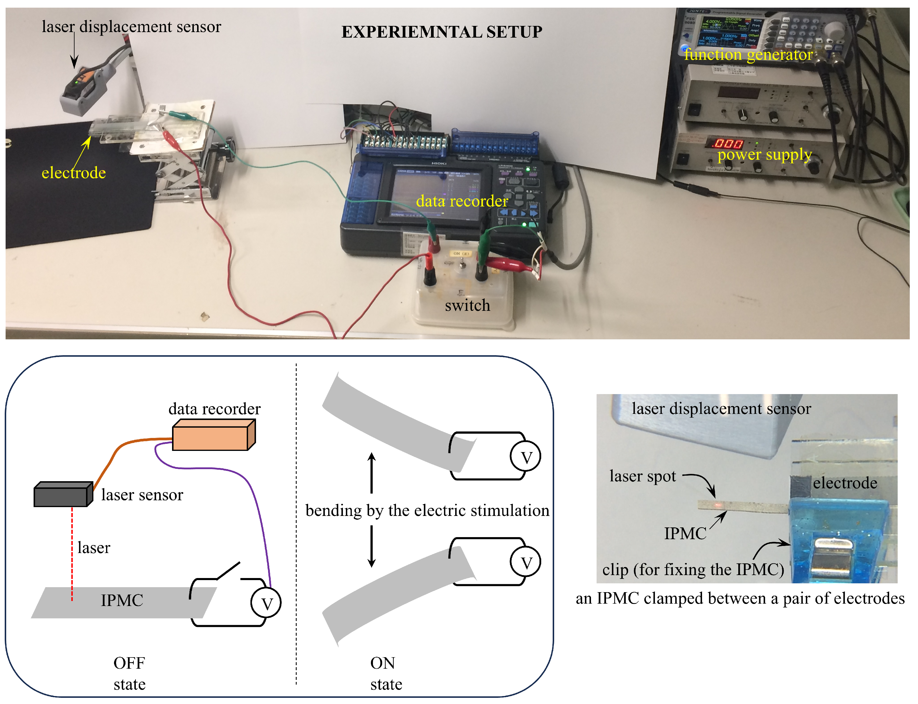
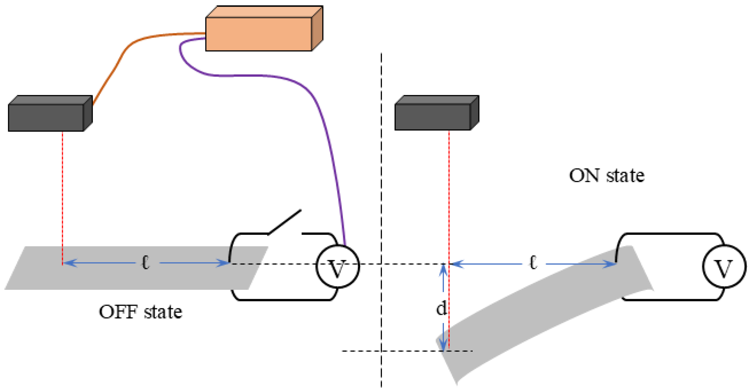
3. Experiment of Bending Tests

Bending tests were conducted using the setup shown in Figure 3. A horizontally clamped IPMC was subjected to external electric stimulation, and the induced bending (the vertical displacement of the IPMC tip) was measured using a laser displacement sensor. Data from the laser displacement sensor were recorded over time using a data recorder, shown in Figure 3, along with simultaneous measurements of voltage and current.

3.1. Bending Response Under Constant Voltage

A constant voltage of 2 V was applied to the IPMC, and its displacement (denoted as d) was measured using a laser displacement sensor. The measured displacement was later converted into the bending curvature [34]. The data of the IPMC’s vertical displacement, d, were converted into curvature using Equation (1); see the definitions of d and in Figure 4.
C = 2 2 + d 2 C : bending curvature

3.2. Bending Response to Alternate Voltage

An alternating voltage with an amplitude of 2 V was applied to the IPMC at frequencies of 0.05 Hz and 0.005 Hz. The resulting IPMC bending displacement was measured using a laser displacement sensor, and the measured displacement was later converted into curvature, as performed in the experiment described in Section 3.1.

4. Results and Discussion

4.1. Silver-Coated IPMC

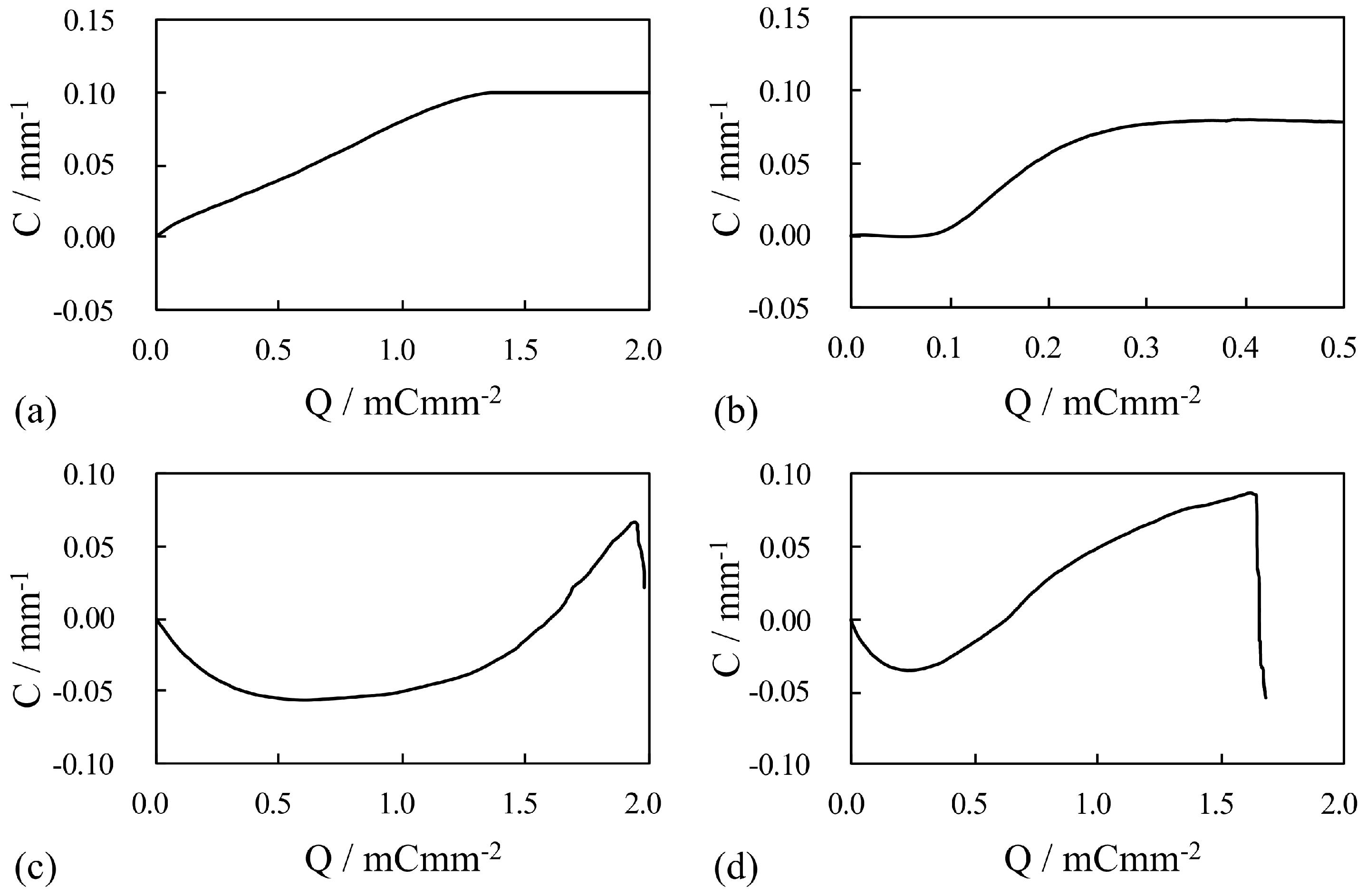
4.1.1. Bending Under a Constant Voltage

Figure 5 shows the curvature vs. time behavior of the IPMCs under a constant voltage of 2 V. All the IPMCs primarily exhibited bending in the same direction, resulting in a positive curvature. However, Ag-AMV and Ag-AMVN showed negative bending curvatures for 20–30 s immediately after the start of the bending tests. Additionally, both IPMCs reached a negative curvature again a few hundred seconds after the start of the tests. So, both Ag-AMV and Ag-AMVN exhibited unpredictable bending behavior in response to the external electric stimulation. Ag-CMV and Ag-CMVN exhibited constant bending curvatures even though a constant voltage of 2 V was continuously applied to these two IPMCs. This is a highly preferable bending characteristic for achieving a practical IPMC. We would like to discuss the bending characteristics of all four IPMCs more in detail.
All the IPMCs exhibited positive bending, though Ag-AMV and Ag-AMVN also showed negative bending curvatures. The positive bending of all four IPMCs can be attributed to the silver layers on their surfaces, as the silver layer is a feature they all had in common. Our earlier studies suggest that the redox reaction of silver under electric stimulation causes IPMC bending. Therefore, the positive bending observed in all four IPMCs was likely due to the redox reaction of their silver layers [35,36,37]. The silver redox reaction is even visible to the naked eye; specifically, the white–silver color turns into black–silver oxide due to the oxidation process, while the black–silver oxide turns back to white–silver during the reduction process. However, only Ag-AMV and Ag-AMVN exhibited negative curvatures in addition to positive ones, while Ag-CMV and Ag-CMVN did not show negative curvatures at all. AMV and AMVN carry positive immobile charges from amines, whereas CMV and CMVN carry negative immobile charges from sulfonic groups. We speculate that the positive immobile charges in Ag-AMV and Ag-AMVN were responsible for inducing the negative bending curvatures. We have not yet identified how these immobile charges were involved in determining the bending direction of the IPMCs.
Our previous work suggests that the bending curvature of Ag-CMV is largely governed by the current (or total charge) that Ag-CMV undergoes [30,31,34]. Therefore, it is important to examine the current diagrams for all the IPMCs. When conducting the experiments to obtain the diagrams shown in Figure 5, we recorded the current per unit surface area of individual IPMCs as a function of time, denoted as I(t). Figure 6 shows the time dependence of the current induced in the individual IPMCs during the experiments used to generate the diagrams in Figure 5.
Quite intriguingly, Figure 5 and Figure 6 suggest that the bending motion of Ag-CMV and Ag-CMVN was induced only when the current was non-zero. On the other hand, Ag-AMV and Ag-AMVN continued to exhibit bending even though the induced current was zero. Therefore, the bending controllability of Ag-CMV and Ag-CMVN through current control must be practically utilizable, while the bending controllability of Ag-AMV and Ag-AMVN is unlikely to be useful. Using Equation (2), it was possible to numerically calculate the total charge as a function of time, denoted as Q(t), for all four IPMCs. We then investigated the “Curvature vs. Charge” relationship for these four IPMCs. The results are shown in Figure 7. There is a well-ordered relationship between the curvature (C) and charge (Q) for Ag-CMV and Ag-CMVN; namely, the constant increase in Q led to an increase in C. On the other hand, the curvature of both Ag-AMV and Ag-AMVN decreased, then increased, and then decreased again as Q increased, as clearly seen in Figure 7c,d. Therefore, it is unlikely that the curvature of Ag-AMV and Ag-AMVN can be controlled through charge (or current) control.
Q ( t ) = 0 t I ( t ) d t

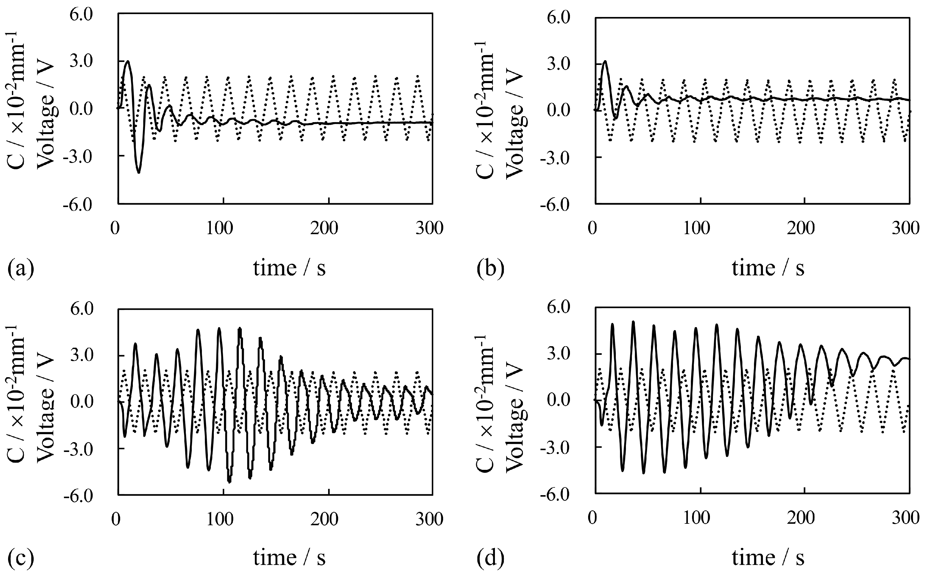
4.1.2. Bending Under an Alternating Voltage

For the practical use of IPMC actuators, understanding their dynamic bending characteristics is important. Hence, we investigated the bending behavior of all four IPMCs under an alternating voltage. Figure 8 shows the “Curvature vs. Time” behavior (solid curve) of the IPMCs under an alternating voltage with a 2 V amplitude and a frequency of 0.05 Hz. The alternating voltage profile (dotted curve) is superimposed on the same diagram. Both Ag-CMV and Ag-CMVN exhibited similar bending, while Ag-AMV exhibited bending opposite to that of Ag-CMV and Ag-CMVN. Ag-AMVN also exhibited opposite bending, similar to Ag-AMV. The reason for the opposite bending of Ag-AMV and Ag-AMVN compared to Ag-CMV and Ag-CMVN was likely due to the fast frequency (0.05 Hz) of the alternating voltage. Figure 5c,d suggest that Ag-AMV and Ag-AMVN exhibited negative bending curvatures in the early stage of the voltage application. Therefore, the bending curvatures of Ag-AMV and Ag-AMVN were opposite to those of Ag-CMV and Ag-CMVN. The “Curvature vs. Time” data curves from Figure 8 are consolidated into a single diagram in Figure 9.
On the other hand, all four IPMCs exhibited positive bending curvatures around t = 50 s, as suggested in Figure 5. Hence, all four IPMCs were expected to bend in the same direction under an alternating voltage with a low frequency, such as a 200 s (50 s × 4) period (frequency = 0.005 Hz). Figure 10 shows the time dependence of the bending curvatures of Ag-CMV, Ag-AMV, Ag-CMVN, and Ag-AMVN when the alternating applied voltage frequency was quite low, at 0.005 Hz. As expected, all the IPMCs exhibited very similar bending characteristics. For example, all the IPMCs exhibited positive bending curvatures at around t = 100 s and negative curvatures at around t = 200 s. Therefore, regardless of the sign of immobile charges contained in the IPMCs, all of them bent in the same direction according to the polarity of the applied voltage. The experimental data curves of “Curvature vs. Time” shown in Figure 10 are consolidated into a single diagram in Figure 11. This clearly suggests that all four IPMCs bended in the same direction.
As discussed in the previous section, the successful bending control of Ag-AMV and Ag-AMVN with external electrical stimulation is not feasible. In fact, the bending direction of these materials in response to external electric stimulation does not necessarily depend on the polarity of the applied voltage and significantly depends on the applied voltage frequency, as described in this section. In contrast, Ag-CMV and Ag-CMVN are promising IPMCs. Therefore, we will specifically analyze the “Current vs. Time” and “Curvature vs. Charge” relationships for Ag-CMV and Ag-CMVN. Figure 12a,b shows the “Current vs. Time” and “Curvature vs. Charge” data for Ag-CMV and Ag-CMVN, obtained during the experiment for Figure 8. Figure 12c,d display relatively well-ordered traces, which approximate a linear relationship. If these traces were perfectly linear, the curvature of Ag-CMV could be precisely controlled by adjusting the quantity of the charge applied to Ag-CMV and Ag-CMVN.
The favorable characteristics of Ag-CMV and Ag-CMVN become even clearer when we conduct the same analysis of the current (charge) and curvature data obtained from the experiment for Figure 10. Figure 13 shows the “Current vs. Time” and “Curvature vs. Charge” relationships, where the data were obtained during the experiment for Figure 10. The “Curvature vs. Charge” plots for both Ag-CMV and Ag-CMVN display a well-ordered relationship. The curve for Ag-CMV is close to linear, while that for Ag-CMVN is perfectly linear. Therefore, precise bending control of Ag-CMV and Ag-CMVN through charge (or current) control is feasible.
For comparison, we present the “Curvature vs. Charge” plot for Ag-AMV in Figure 14, with data obtained from the experiment for Figure 10c. This plot shows that the relationship between the curvature and charge for Ag-AMV deviated significantly from a linear pattern. The same was true for Ag-AMVN (though the diagram is not shown here). Neither Ag-AMV nor Ag-AMVN exhibited a linear or near-linear relationship between their curvature and charge.
Therefore, the silver coating and dehydration treatment appear to have had a beneficial effect in improving the IPMCs’ bending controllability. However, this beneficial effect was limited to IPMCs consisting of ion exchange membranes containing immobile negative charges, such as Ag-CMV and Ag-CMVN.

4.2. Bending of Au-Coated IPMCs Under Constant Voltage

All four types of IPMCs exhibited positive bending under the prolonged application of a constant voltage, as shown in Figure 5 (even though the further prolonged application of a constant voltage again made the bending curvatures of Ag-AMV and Ag-AMVN negative.). A common feature among these IPMCs was the presence of silver electrodes, which suggests that the silver electrodes were responsible for the positive bending direction. In contrast, Ag-AMV and Ag-AMVN exhibited negative bending in the early stage of the constant voltage application, whereas both Ag-CMV and Ag-CMVN exhibited positive bending curvatures. As described in Section 4.1.1, we speculate that the bending observed in the early state shown in Figure 5 was influenced by the sign of the immobile charges carried by the ion exchange membranes of the IPMCs.
To investigate how bending behavior might change with an electrochemically inactive material, such as gold (Au), by replacing the silver electrode layer, we fabricated an IPMC with gold electrodes. Gold foils were attached to the surfaces of each type of ion exchange membrane. These IPMCs are hereafter referred to as Au-CMV, Au-CMVN, Au-AMV, and Au-AMVN, respectively.
Bending tests with these IPMCs were conducted under a constant applied voltage of 2 V. The results are shown in Figure 15 together with the data of Figure 5 which shows the bending of the Ag-coated IPMCs. We found that all Au-coated IPMCs exhibited only negligible bending, in contrast to the significant bending observed in all Ag-coated IPMCs, suggesting that silver layers are essential for effective bending in IPMCs, regardless of the bending direction.
The Ag-coated and Au-coated IPMCs’ bending characteristics differed completely from each other. The Ag-coated IPMCs exhibited visible bending, observable even with the naked eye, while the Au-coated IPMCs did not bend at all. Therefore, simply applying electrical stimulation to IPMCs is not sufficient to induce the bending of IPMCs.
Typically, IPMC electrodes are formed using electroless plating [17,18,19]. This process requires the use of various chemical agents. We speculate that these chemicals are absorbed into the IPMC body and remain there. These residual chemicals are likely to play a fundamental role in inducing effective bending in IPMCs. In fact, this effect is known as doping, which is used to enhance IPMC bending performance [19,20]. However, our Au-coated IPMCs did not undergo doping treatment. Consequently, the bending of the Au-coated IPMCs was not expected. As we explained in Section 2, the commonly used metal layer of IPMCs is platinum, which is chemically stable, as gold is. However, unlike our Au-coated IPMCs, it has been reported that platinum-coated IPMCs are also doped inadvertently in the platinum electroless plating process. Therefore, multiple species of ions must have been involved in the bending of our IPMCs.
To sum up, either or both the silver layer redox reaction and doped chemicals appear to play a role in controllable and effective IPMC bending. However, we have not yet identified how the redox reaction of the silver layer and/or doped chemicals leads to IPMC bending. We speculate that molecular and/or atomic structural changes caused by these redox reactions result in the bending. In fact, our previous study on a silver-coated IPMC using EDX suggests that the redox reaction of the silver layers (silver ⇋ silver oxide) occurs upon the application of electrical stimulation [37].
The exact mechanism governing bending induction and the factors that determine bending direction in IPMCs remain unknown. However, our Ag-coated IPMCs consistently exhibited greater bending than the Au-coated IPMCs. Specifically, Ag-CMV and Ag-CMVN demonstrated better bending controllability in response to external electric stimulation compared to Ag-AMV and Ag-AMVN.

5. Conclusions

Achieving a practical IPMC actuator is still a distant goal, but we have gained important insights into IPMC’s characteristics. IPMCs with electrochemically active silver surfaces produce more effective bending compared to those with electrochemically inactive gold surfaces. Dehydration treatment also appears to be essential, as our IPMCs made with Ag-coated cation exchange membranes (Ag-CMV/CMVN) showed better bending controllability in response to electric stimulation. However, this treatment was not effective for Ag-coated anion exchange membranes (Ag-AMV/AMVN). This suggests that the sign of the immobile charge in the ion exchange membrane determines IPMCs’ bending controllability and that negative immobile charges are preferable for improving IPMCs’ bending controllability.
While we do not doubt the conventional bending mechanism of IPMCs, in which the shift of hydrated mobile ions causes bending (as illustrated in Figure 1), other factors, such as the incorporation of some ions into the IPMC body during the electroless plating process (which can be considered doping), as well as redox reactions on the metal surface layers, also significantly contribute to bending.

Author Contributions

Conceptualization, H.T. and I.K.; Methodology, H.T., I.K. and S.T.; Analysis, H.T., I.K., S.T., W.L. and M.S.; Original draft preparation, H.T.; Review and editing, H.T.; Funding acquisition, W.L. and M.S. All authors have read and agreed to the published version of the manuscript.

Funding

Kawamura Electric Inc. (Japan).

Data Availability Statement

All data that supports the findings of this study is available within the article and the references.

Conflicts of Interest

Dr. Wenyi Lin has received research grants from Kawamura Electric Inc.

References

  1. Katchalsky, A. Polyelectrolytes and Their Biological Interactions. Phys. Chem. Macromol. 1949, 4, 9–41. [Google Scholar] [CrossRef] [PubMed]
  2. Katchalsky, A.; Zwick, M. Mechanochemistry and ion exchange. J. Polym. Sci. 1955, 16, 221–234. [Google Scholar] [CrossRef]
  3. Okuzaki, H.; Osada, Y. Classification and Research Trend of Soft Actuators. JSPE 2014, 80, 709–712. [Google Scholar]
  4. Jiang, J.; Lin, C.; Xu, S.; Yu, Y.; Yao, L.; Huang, Z. Application-Oriented Modeling of Soft Actuator Ionic Polymer-Metal Composites: A Review. Adv. Intell. Syst. 2024, 6, 2300568. [Google Scholar] [CrossRef]
  5. Tanaka, T. Classification and Research Trend of Soft Actuators. Phys. Rev. Lett. 1978, 40, 820–823. [Google Scholar] [CrossRef]
  6. Tanaka, T. Gels. Sci. Am. 1982, 244, 124–138. [Google Scholar] [CrossRef] [PubMed]
  7. Tokita, M. Phase Transition of Gels—A Review of Toyoichi Tanaka’s Research. Gels 2022, 8, 550. [Google Scholar] [CrossRef] [PubMed]
  8. Oguro, K.; Kawami, Y.; Takenaka, H. Bending of anion-Conducting Polymer Film-Electrode Composite by an Electric Stimulus at Low Voltage. J. Micromach. Soc. 1992, 5, 27–30. [Google Scholar]
  9. Kanno, R.; Tadokoro, S.; Takamori, T.; Hattori, M.; Oguro, K. Linear Approximate Dynamic Model of ICPF (Ionic Conducting Polymer Gel Film) Actuator. In Proceedings of the 1996 IEEE International Conference on Robotics and Automation, Minneapolis, MN, USA, 22–28 April 1996; pp. 219–225. [Google Scholar]
  10. Salehpoor, K.; Shahinpoor, M.; Mojarrad, M. Linear and Platform Type Robotic Actuators Made From Ion-Exchange Membrane-Metal Composites. In Proceedings of SPIE Conference on Smart Materials Technologies, San Diego, CA, USA, 3–4 March 1997; Volume 3040, pp. 192–197. [Google Scholar]
  11. Guo, S.; Fukuda, T.; Kato, N.; Oguro, K. Development of Underwater Microrobot Using ICPF Actuator. In Proceedings of the 1998 IEEE International Conference on Robotics and Automation, Leuven, Belgium, 16–20 May 1998; pp. 1829–1834. [Google Scholar]
  12. Bar-Cohen, Y.; Xue, T.; Shahinpoor, M.; Simpson, J.O.; Smith, J. Low-mass muscle actuators using electroactive polymers (EAP). In Proceedings of the SPIE Conference on Smart Materials Technologies, San Diego, CA, USA, 1–5 March 1998; Volume 3324, pp. 218–223. [Google Scholar]
  13. Shahinpoor, M.; Bar-Cohen, Y.; Xue, T.; Simpson, J.O.; Smith, J.; Hung, M.; Sheng, W. Some Experimental Results on Ionic Polymer-Metal Composites (IPMC) As Biomimetic Sensors and Actuators. In Proceedings of the SPIE Conference on Smart Materials Technologies, San Diego, CA, USA, 1–5 March 1998; Volume 3324, pp. 251–267. [Google Scholar]
  14. Onishi, K.; Sewa, S.; Asaka, K.; Fujiwara, N.; Oguro, K. The effects of counter ions on characterization and performance of a solid polymer electrolyte actuator. Elcctrochimica Acta 2001, 46, 1233–1241. [Google Scholar] [CrossRef]
  15. Yun, K.; Kim, W.-J. System identification and microposition control of ionic polymer metal composite for three-finger gripper manipulation. Proc. Inst. Mech. Eng. Part I J. Syst. Control Eng. 2005, 220, 539–551. [Google Scholar] [CrossRef]
  16. Hung, M.; Sheng, W. Robust Adaptive Control with Leakage Modification for a Nonlinear Model of Ionic Polymer Metal Composites (IPMC). In Proceedings of the 2008 IEEE International Conference on Robotics and Biomimetics, Bangkok, Thailand, 21–26 February 2009; pp. 1783–1788. [Google Scholar]
  17. He, Q.; Song, L.; Yu, M.; Dai, Z.D. Fabrication, characteristics and electrical model of an ionic polymer metal-carbon nanotube composite. Smart Mater. Struct. 2015, 24, 07S001. [Google Scholar] [CrossRef]
  18. Park, J.H.; Lee, S.W.; Song, D.S.; Jho, J.Y. Highly Enhanced Force Generation of lonic Polymer-Metal Composite Actuators via Thickness Manipulation. ACS Appl. Mater. Interfaces 2015, 7, 16659–16667. [Google Scholar] [CrossRef] [PubMed]
  19. Wang, M.; Yu, M.; Lu, M.; He, Q.; Ji, K.; Liu, L. Effects of Cu2+ Counter Ions on the Actuation Performance of Flexible Ionic Polymer Metal Composite Actuators. J. Bionic Eng. 2018, 15, 1047–10567. [Google Scholar] [CrossRef]
  20. Zhai, Z.; Tian, A.; Zhang, X.; Du, H.; Wang, Y. Performance prediction of IPMC modified with SiO2-SGO based on backpropagation neural network. Nanotechnol. Precis. Eng. 2024, 7, 043007. [Google Scholar] [CrossRef]
  21. Hara, S.; Zama, T.; Takashima, W.; Kaneto, K. Artificial Muscles Based on Polypyrrole Actuators with Large Strain and Stress Induced Electrically. Polym. J. 2004, 36, 151–161. [Google Scholar] [CrossRef]
  22. Choi, H.-J.; Song, Y.-M.; Chung, I.; Ryu, K.-S.; Jo, N.-J. Conducting polymer actuator based on chemically deposited polypyrrole and polyurethane-based solid polymer electrolyte working in air. Smart Mater. Struct. 2009, 18, 024006. [Google Scholar] [CrossRef]
  23. Chiba, S.; Stanford, S.; Pelrine, R.; Kornbluh, R.; Prahlad, H. Electroactive Polymer Artificial Muscle. JRSJ 2006, 24, 466–470. [Google Scholar] [CrossRef]
  24. O’Brien, B.M.; Rosset, S. Ion implanted dielectric elastomer circuits. Appl. Phys. A Mater. Sci. Process. 2013, 111, 943–950. [Google Scholar] [CrossRef]
  25. Yip, M.C.; Niemeye, G. High-Performance Robotic Muscles from Conductive Nylon Sewing Thread. In Proceedings of the 2015 IEEE International Conference on Robotics and Automation (ICRA), Seattle, WA, USA, 26–30 May 2015. [Google Scholar]
  26. Wang, S.; Huang, H.; Huang, H.; Li, B.; Huang, K. A Lightweight Soft Gripper Driven by Self-Sensing Super-Coiled Polymer Actuator. IEEE Robot. Autom. Lett 2021, 6, 2775–2782. [Google Scholar] [CrossRef]
  27. Musavir, B.; Rajendran, P. A review on electroactive polymers development for aerospace applications. J. Intell. Mater. Syst. Struct. 2018, 18, 3681–3695. [Google Scholar] [CrossRef]
  28. Porfiri, M.; Leronni, A.; Bardella, L. An alternative explanation of back-relaxation in ionic polymer metal composites. Extrem. Mech. Lett. 2017, 13, 78–83. [Google Scholar] [CrossRef]
  29. Annabestani, M.; Sayad, M.H.; Esmaeili-Dokht, P.; Gorji, R.; Fardmanesh, M. Eliminating Back Relaxation in Large-Deformable IPMC Artificial Muscles: A Noise-Assistive Pattern-Free Electrode Approach. In Proceedings of the 27th National and 5th International Iranian Conference on Biomedical Engineering (ICBME), Tehran, Iran, 26–27 November 2020. [Google Scholar]
  30. Onouchi, Y.; Sasaki, M.; Tamagawa, H. Current-controlled Selemion bending in the controlled humidity environment. Sens. Actuators B Chem. 2009, 135, 465–471. [Google Scholar] [CrossRef]
  31. Sasaki, M.; Lin, W.; Tamagawa, H.; Ito, S.; Kikuchi, K. Self-Sensing Control of Nafion-Based Ionic Polymer-Metal Composite (IPMC) Actuator in the Extremely Low Humidity Environment. Actuators 2013, 2, 74–85. [Google Scholar] [CrossRef]
  32. Nishida, G.; Sugiura, M.; Yamakita, M.; Maschke, B.; Ikeura, R. Multi-Input Multi-Output Integrated Ionic Polymer-Metal Composite for Energy Controls. Micromachines 2012, 3, 126–136. [Google Scholar] [CrossRef]
  33. Tamagawa, T.; Nogata, F.; Watanabe, T.; Abe, A.; Yagasaki, K.; Jin, J.-Y. Influence of metal plating treatment on the electric response of Nafion. J. Mater. Sci. 2003, 38, 1039–1044. [Google Scholar] [CrossRef]
  34. Onouchi, Y.; Tamagawa, H.; Sasaki, M. Dependence of curvature of dehydrated Selemion on the total charge and environmental humidity. JSAEM 2009, 17, 59–64. [Google Scholar]
  35. Tamagawa, H.; Nogata, F.; Popovic, S. Roles of Ag redox reaction and water absorption inducing the Selemion bending. J. Membr. Sci. 2005, 251, 145–150. [Google Scholar] [CrossRef]
  36. Tamagawa, H.; Nogata, F. Atomic structural change of silver-plating layers on the surfaces of Selemion, resulting in its excellent bending controllability. Sens. Actuators B Chem. 2006, 114, 781–787. [Google Scholar] [CrossRef]
  37. Tamagawa, H.; Okada, K.; Mulembo, T.; Sasaki, M.; Naito, K.; Nagai, G.; Nitta, T.; Yes, K.-C.; Ikeda, K. Simultaneous Enhancement of Bending and Blocking Force of an Ionic Polymer-Metal Composite (IPMC) by the Active Use of Its Material Characteristics Change. Actuators 2019, 8, 29. [Google Scholar] [CrossRef]
Figure 1. A conventional bending mechanism and the state of mobile protons. (a) IPMC under zero electric stimulation. (b) Bending induction due to the transversal movement of hydrated protons, which is caused by the electric field, toward the negative electrode side of the IPMC. Green arrows indicate the direction of the movement of hydrated protons.
Actuators 13 00517 g001
Figure 2. The conventional theory of the bending relaxation process. (a,b): Hydration water molecules are ripped off from the protons and diffuse back, resulting in bending relaxation, but the protons continue to stay near the negative electrode side. Orange arrows indicate the direction of the water molecules ripped off from the protons.
Actuators 13 00517 g002
Figure 3. Photos: The experimental setup and an IPMC clamped between a pair of electrodes. Illustrations: The IPMC shows no bending in the OFF state. It bends in the ON state, and its bending direction changes in response to the polarity of the electric stimulation (the laser displacement sensor and data recorder are not shown to avoid cluttering the figure).
Actuators 13 00517 g003
Figure 4. Conversion of IPMC’s vertical displacement (d) into the curvature (C).
Actuators 13 00517 g004
Figure 5. Curvature vs. time under a constant 2 V voltage. (a) Ag-CMV; (b) Ag-CMVN; (c) Ag-AMV; (d) Ag-AMVN. The bending curvature of Ag-AMV became negative after the prolonged application of a constant 2 V voltage.
Actuators 13 00517 g005
Figure 6. Current vs. time (diagrams for 0 ≤ t ≤ 300 and for the early stage) when the experiments to obtain the diagrams shown in Figure 5 were conducted. The current represents the current for a unit surface area of the IPMCs. (a) Ag-CMV; (b) Ag-CMVN; (c) Ag-AMV; (d) Ag-AMVN.
Actuators 13 00517 g006
Figure 7. Curvature vs. charge when the experiments for obtaining the diagrams shown in Figure 5 were conducted The charge represents the total charge for a unit surface area of an IPMC. (a) Ag-CMV; (b) Ag-CMVN; (c) Ag-AMV; (d) Ag-AMVN.
Actuators 13 00517 g007
Figure 8. Curvature (solid curve) vs. time under an alternating voltage (dotted curve) with a 2 V amplitude and a frequency of 0.05 Hz. (a) Ag-CMV; (b) Ag-CMVN; (c) Ag-AMV; (d) Ag-AMVN.
Actuators 13 00517 g008
Figure 9. Curvature vs. time from t = 0 s to 80 s, as shown in Figure 8. Thin curve: Ag-CMV; thick curve: Ag-CMVN; dotted curve: Ag-AMVN; dashed curve: Ag-AMVN.
Actuators 13 00517 g009
Figure 10. Curvature vs. time (solid curve) under an alternating voltage (dotted curve) with an amplitude of 2 V and a frequency of 0.005 Hz. (a) Ag-CMV; (b) Ag-CMVN; (c) Ag-AMV; (d) Ag-AMVN.
Actuators 13 00517 g010
Figure 11. Curvature vs. time, as shown in Figure 10. U: upward bending; D: downward bending; thin curve: Ag-CMV thick curve: Ag-CMVN; dotted curve: Ag-AMVN; dashed curve: Ag-AMVN.
Actuators 13 00517 g011
Figure 12. Current (dotted line) and curvature (solid line) vs. time. (a) Ag-CMV; (b) Ag-CMVN, curvature vs. charge; (c) Ag-CMV; (d) Ag-CMVN.
Actuators 13 00517 g012
Figure 13. Current (dotted line) and curvature (solid line) vs. time. (a) Ag-CMV; (b) Ag-CMVN, curvature vs. charge; (c) Ag-CMV; (d) Ag-CMVN.
Actuators 13 00517 g013
Figure 14. Curvature vs. charge, Ag-CMVN.
Actuators 13 00517 g014
Figure 15. Curvature vs. time under a constant 2 V voltage. Thin line: Ag-coated IPMC (all the data are from Figure 5); thick line: Au-coated IPMC; (a) Ag-CMV and Au-CMV; (b) Ag-CMVN and Au-CMVN; (c) Ag-AMV and Au-AMV; (d) Ag-AMVN and Au-AMVN.
Actuators 13 00517 g015
Disclaimer/Publisher’s Note: The statements, opinions and data contained in all publications are solely those of the individual author(s) and contributor(s) and not of MDPI and/or the editor(s). MDPI and/or the editor(s) disclaim responsibility for any injury to people or property resulting from any ideas, methods, instructions or products referred to in the content.

