Fundamental Study on Force-Projecting Bilateral Control for Pneumatically Driven Follower Device


1
Department of Mechanical Engineering, National Institute of Technology, Tokyo College, 1220-2 Kunugida-machi, Hachioji 193-0997, Japan
2
Department of Mechanical Engineering, Nagaoka University of Technology, 1603-1 Kamitomioka, Nagaoka 940-2188, Japan
*
Author to whom correspondence should be addressed.
†
These authors contributed equally to this work.
Actuators 2024, 13(2), 56; https://doi.org/10.3390/act13020056
Submission received: 21 December 2023
/
Revised: 23 January 2024
/
Accepted: 26 January 2024
/
Published: 31 January 2024
(This article belongs to the Section Actuators for Robotics)
Abstract
:This paper proposes the application of force-projecting bilateral control to a master-follower teleoperation system with pneumatic drive on the follower side and evaluates its effectiveness. The proposed method directly projects the operating force on the master side to the driving force on the follower side, eliminating the need for both position control and external force detection on the follower side, thereby solving the problem of low rigidity and response delay of a pneumatic servo system and providing highly stable sensor-less force presentation against variable environments. In this study, dynamic response analyses of a 1-DOF master-follower system were performed by numerical simulation using a linear system model, followed by experimental verification by implementing an actual system with an external force estimator. The results showed that the proposed force-projecting bilateral control has significantly higher positioning rigidity and better force control stability than the conventional force-reflecting bilateral control. A theoretical consideration was also given using the equivalent transformation of force transfer functions to provide evidence of high stability.
1. Introduction
1.1. Research Background
Bilateral control is a teleoperation method that simultaneously controls the position and force of both the master and follower and has been studied in the fields of surgical robotics [1], space robotics [2], and radioactive material manipulation [3]. These control methods are based on the assumption that they can be applied to electric manipulators with high positioning rigidity and fast force response. On the other hand, pneumatic manipulators have a high affinity with humans and environments because of their softness caused by the compressibility of air, lightweight, high power, high shock and vibration resistance, electromagnetic noise-free, and ability to estimate external force without a force sensor. Taking advantage of these characteristics, pneumatic manipulators have been applied to surgical assist robots [4,5], humanoid robots [6], rehabilitation robots [7,8], construction machinery operating robots [9] and so on. For these systems, accurate and stable bilateral control is also desired for remote work and teaching operations. However, most existing bilateral control methods are systems that assume high rigidity and fast response from the follower robot. If these are applied to a low-rigidity servo device such as a pneumatic manipulator, the positional deviation between the master and follower may reduce operability, and the system may become unstable due to a delayed response. Furthermore, in environments where the robot cannot be equipped with a force sensor, the above problems are more likely to occur as uncertain values of external force estimation are fed back to the master. Therefore, it is necessary to develop a practical, highly rigid, and highly stable bilateral control method suitable for such a compliant device with low rigidity and low response.
1.2. Related Works
Bilateral control begins with basic control methods such as symmetrical bilateral control and force-reflecting bilateral control (Force-Reflecting Type), and many methods have been developed to reproduce delicate tactile sensations and obtain high stability. Miyazaki et al. [10] proposed a parallel bilateral control with a small phase delay and high stability by giving equal position commands to the master and follower. Tachi et al. [11,12,13] proposed an impedance-controlled bilateral control that can determine the virtual mass and viscosity of the master and follower to arbitrary values. In particular, Lawrence [14] defined “transparency” as a quantitative index of force sensation reproduction in bilateral control, and Yokokoji et al. [15,16,17] proposed a 4-channel bilateral control that achieves ideal transparency. In recent years, Michel et al. [18] presented an adaptive impedance control architecture for robotic teleoperation of contact tasks using the ’Learning from Demonstration’ framework. However, these control methods assume a system with high control rigidity, so they are not suitable for flexible pneumatically driven systems. In addition, a force sensor is required to measure external force, which is difficult to use in harsh operating environments where sensors cannot be installed on the device. The latest research trend includes an identification-free, data-driven control method proposed by Kucukdemiral et al. [19] under physical limitations and norm-bounded disturbances. Data-driven control has been successful in many applications, but it can be difficult to generalize in terms of data quality and reliability. A model-based approach is still useful for addressing specific constraints and requirements.
On the other hand, there are studies such as Iida et al. [20,21,22] that have applied an observer-based acceleration control theory [23] to bilateral control and achieved high transparency without using force sensors. This method uses a disturbance observer (DOB) and a reaction force observer (RFOB) to achieve high-speed force control without a force sensor. Advancing this technique, Kimura et al. [24] proposed a novel admittance-based bilateral control system using only two communication channels without deteriorating the control performance, which results in communication data reduction. However, this acceleration-based bilateral control requires the actuator to have quick responsiveness to perform acceleration control well and is not suitable for pneumatic actuators that have a significant response delay in driving force.
When it comes to pneumatically driven systems, even in recent years, a great deal of research has been conducted to improve position controllability [25,26,27]. In these studies, the position control bandwidth was quite low, making it inherently difficult to achieve high stiffness and stability. On the other hand, many studies on sensor-less external force estimation take advantage of the high back-drivability of pneumatic actuators [28,29]. Although these studies have pursued more rigorous dynamic models that include nonlinearities, they still leave non-negligible levels of estimation error. Related works on bilateral control systems for pneumatic manipulators include a control method using a passive controller for a force amplification system developed by Durbra et al. [30], and a sliding mode control method for controlling pneumatic pressures using an inexpensive solenoid valve proposed by Moreau et al. [31]. In addition, Shono et al. [32] designed and implemented an encrypted controller for a force feedback-type bilateral control system using pneumatic cylinders. However, these methods have not solved the aforementioned problems of pneumatic servo drive such as low response and low rigidity. Tadano et al. [33,34] developed pneumatically driven robotic surgical instruments capable of external force estimation without using force sensors and constructed the Force-Reflecting Type bilateral control system. However, there remained problems, such as large position deviation between the master and follower due to low control rigidity on the follower side, and errors in external force estimation due to modeling errors, resulting in system instability and an unnatural operational feel.
In contrast to the existing studies mentioned above, Kaneko et al. [35] have proposed a robust control method that does not require high-precision specifications for bilateral control systems. Kanaoka et al. [36,37] named this method “force-projecting bilateral control” and proposed a design method that can be practically applied. The force-projecting bilateral control (Force-Projecting Type) directly projects operating forces on the master side to the driving force on the follower side and was applied to the control of force-amplifying manipulators [38] that require high rigidity and large output. This control method does not require position control on the follower side; thus, the system performance does not depend on the control stiffness of the follower device. Another important point is that there is no need for external force feedback from the follower to the master, so there is no need for force sensors or external force estimation.
1.3. Research Objective
Therefore, in this study, we focus on the advantages of the force-projecting bilateral control mentioned above and aim to solve the problems of positional deviation and system instability caused by the low rigidity and slow response characteristics of a pneumatically driven follower device.
This study deals with a one-degree-of-freedom (DOF) bilateral control system consisting of an electric drive master and a pneumatic drive follower with a single-axis linear motion to simplify the problem and facilitate an essential understanding of the system behavior. First, a theoretical model of the system is constructed, and its transient and frequency responses are investigated by numerical simulation. Next, an actual system is developed assuming a situation in which the follower-side device cannot be equipped with a force sensor. The transient and frequency responses are investigated experimentally in the same way as the simulation. In addition, a manual operation experiment by a human is performed to investigate the system’s behavior and operability. Through numerical analyses and experiments, we compare the control performance and stability of the proposed Force-Projecting Type with those of the conventional Force-Reflecting Type and demonstrate the superiority of the Force-Projecting Type.
2. System Modeling and Control Architecture
This section describes the linear analytical models of the two bilateral control systems for numerical simulation. The modeling approach is common to our previous study [39], but the model parameters are fully updated to match the values of the actual system shown in Section 4. In addition, the derivations of the theoretical models are provided in more detail than our previous study [39].
2.1. One-DOF Master-Follower Dynamic Model
A bilateral control system is a teleoperation technique in which a master and a follower control each other’s position to achieve the desired operability and reproducibility. To analyze such a system, we consider a master-follower model with one DOF, as shown in Figure 1, which represents the mechanical dynamics of the manipulator. The physical parameters and constants that each symbol and subscript signify are shown in Table 1. In this model, on the master side the operating force applied by the operator, the master driving force , and the damping force act on the master mass , and acceleration is generated. Similarly, on the follower side, the reaction force received from the environment, the follower driving force , and the damping force act on the follower mass , generating an acceleration . In such a model, the equation of motion of the master can be expressed as (1).
Similarly, the equation of motion of the follower can be expressed as (2).
Next, the Laplace transform is performed on these equations of motion. Let X, F, and T be the Laplace transforms of x, f, and , respectively, and the Laplace transforms of the Equations (1) and (2) can be expressed as (3) and (4), respectively. In this paper, s denotes the Laplace operator.
Here, these equations of motion are expressed as transfer functions. Transforming the equation of motion of the master (3) results in the following equation:
In Equation (5), the relationship between the force acting on the master and the resulting velocity is described as impedance , and the transfer function related to the dynamic characteristics of the master is obtained.
Similarly, for the follower, transforming the equation of motion of the follower (4) results in the following equation:
In Equation (7), the relationship between the force acting on the follower and the resulting velocity is described as impedance , and the transfer function related to the dynamic characteristics of the follower is obtained.
In addition, we describe a model of the environment in which followers act. As shown in Figure 1, the environment is described as a wall with a spring constant and a damping coefficient . In this study, to make the analyses and experiments convenient, it is assumed that the follower is connected to the environment and never leaves. Under this condition, the reaction force received by the follower can be expressed as follows:
In Equation (9), the relationship between the follower reaction force and the resulting velocity is described as the impedance , and the transfer function related to the dynamic characteristics of the environment is obtained.
2.2. Design of Bilateral Control Systems
This study proposes the application of force-projecting bilateral control to a master-follower system with a pneumatically driven follower device, and evaluates the control performance and stability by comparing it with conventional force-reflecting bilateral control. These two control methods have opposite schemes for exchanging position and force information between the master and follower.
2.2.1. Force-Reflecting Type
First, we describe the conventional force-reflecting bilateral control system. The block diagram of the Force-Reflecting Type used in this study is shown in Figure 2. The meanings of each block and transfer function are shown in Table 2.
In the Force-Reflecting Type, the master driving force projects the reaction force from the environment received by the follower, and the follower driving force is controlled so that the positional deviation of the master and follower becomes zero. This control scheme is given by the following equations:
where denotes a controller of the follower motion.
In Equation (12), and are feedback gains of the follower position and velocity, respectively.
Here, we describe the response delay characteristics of the pneumatically driven follower device, which is the subject of this study. In a typical pneumatic servo drive, a control signal is applied to a servo valve as a voltage to drive a mechanical spool that regulates the cross-sectional area of airflow. Then, air flows into the actuator through the tubing, resulting in an actual driving force by changing the internal pressure. Therefore, the control response is affected by delays due to the performance of the servo valve and air compressibility. In this study, the response delay of the pneumatic drive on the follower is approximately modeled by a linear second-order delay element based on an existing study [4]. The relationship between the driving force command and the actual driving force is expressed as follows:
Therefore, the Equation (11) of the control system can be rewritten, including the pneumatic response delay of the follower side.
2.2.2. Force-Projecting Type
Next, we describe the proposed force-projecting bilateral control system. The block diagram of the Force-Projecting Type developed in this study is shown in Figure 3. The meanings of each block and transfer function are shown in Table 2.
In the Force-Projecting Type, the master driving force is controlled such that the position deviation between the master and follower becomes zero, and the follower driving force is controlled by directly projecting the operational force acting on the master. In the Force-Projecting Type, the control scheme of position and force is the exact opposite of that of the Force-Reflecting Type and can be expressed as follows:
where is the master position controller. It constitutes a PD controller for the master position and is given by the following equation using a position feedback gain and a velocity feedback gain .
3. Numerical Simulation
In this section, numerical analyses are performed on the block diagrams of the two bilateral control systems shown in Figure 2 and Figure 3 to theoretically understand the fundamental behavior of each system.
3.1. Conditions of Analysis
The parameters used in the analyses are shown in Table 3. Each parameter was set according to the identified values of the experimental system described in Section 4. In particular, the identification of the parameters and of the second-order delay element, which represents the response delay characteristics of the pneumatic drive, is described in Section 4.2.
For the Force-Reflecting Type, we set three different position gains on the pneumatically driven follower: “LOW”, “MID”, and “HIGH”. The value of HIGH gain is equal to the position gain of the electric master. While the actual experimental system operated stably only at LOW gain, we show in this simulation that the system becomes unstable with larger values of . The velocity gains and are set as the critical damping factor of the mechanical vibration system.
For the environmental characteristics, two types of environments were prepared: a “HARD” environment with a high spring constant and low damping ratio and a “SOFT” environment with a low spring constant and high damping ratio. In addition, for simplicity, the mass of the environment is assumed to be negligible, and the follower shall always be in contact with the environment, moving in unison and never separating.
For numerical calculations, we used the Control System Toolbox software package in MATLAB® R2022b.
3.2. Step Response
Transient responses were analyzed for the two bilateral control systems and the two types of environments by applying a step input of 5 N to the master operating force . The resulting time responses of the follower reaction force and the position error between master and follower are shown in Figure 4 and Figure 5, respectively. These results provide a clear theoretical evaluation of the behavior of the two types of bilateral control systems. In the Force-Projecting Type, the driving force response delay at the follower is coupled with the position control system, resulting in an oscillatory response. Only the LOW gain barely stabilized in both environments, but the positioning rigidity was very low, resulting in a large position error with the master. On the other hand, in the Force-Projecting Type, the follower reaction force stably and accurately follows the master operation force of 5 N. Position control is not required on the follower side, but is performed by the master side with high positioning rigidity, thus maintaining high system stability and little position error even with a response delay of the pneumatic drive on the follower.
3.3. Frequency Response
To analyze the frequency response, the objective transfer functions and are defined by the following Equations (18) and (19), respectively.
represents the characteristics from the master operating force to the follower reaction force , and represents the characteristics from the master operating force to the position error between the master and follower.
The results of the frequency response analysis for and for the two bilateral control laws are shown in Figure 6 and Figure 7. Because the Bode diagram is effective for stable systems, the analysis for the Force-Reflecting Type was performed only for the LOW gain [N/mm], where the step response was stable in both environments.
First, for the force transfer function in Figure 6, the ideal bilateral control response is , i.e., dB. In the Force-Reflecting Type, the follower reaction force resonates at approximately 20 rad/s in both environments. This resonance originates from the resonance frequency rad/s of the follower position gain and master mass , which causes system instability within the main operating band due to low control stiffness. However, the Force-Projecting Type showed a desired response for its gain close to 0 dB over a wider range than the Force-Reflecting Type. The slight drop in gain above 80 rad/s is thought to be due to the response delay of the pneumatic drive system.
Second, for the position error transfer function in Figure 7, the ideal bilateral control response is , i.e., dB. The smaller the gain, the more desired the response. The Force-Reflecting Type showed a large gain of more than 10 dB and a harmful resonance in both environments due to the low positioning stiffness of the follower. In contrast, the Force-Projecting Type maintained a low value of −25 dB over a wide frequency range and showed no resonance. In the Force-Projecting Type, position control is performed on the master side with high positioning stiffness, which is not affected by the low stiffness of the pneumatic follower.
4. Experimental System Implementation
The numerical analyses in the previous section suggested that the Force-Projecting Type is effective for the basic model of a master-follower system with a pneumatically driven follower. In the following sections, this will be verified through experiments on actual equipment.
4.1. Hardware Configuration
Figure 8 shows the configuration of the 1-DOF master-follower manipulator constructed for the experiment. This manipulator system consists of an electric linear motor on the master side and a pneumatic cylinder on the follower side. The linear motor can move smoothly along the linear bearing guides with almost no frictional resistance and is capable of highly responsive thrust control. The pneumatic cylinder is a low-friction type with a bore diameter of 16 mm, which also has high back-drivability. The end of the cylinder rod on the follower side can be connected to the environmental wall, and the follower reaction force is measured using a force sensor placed on the environmental wall. As shown in Figure 9, a resin plate is used for the “HARD” environment and a sponge is used for the “SOFT” environment. Their mechanical properties are shown in Table 3. A series of experiments were performed with the cylinder rod end of the follower connected to the environmental walls.
The overall configuration of the experimental apparatus and its system diagram is shown in Figure 10 and Figure 11, respectively. The measurement and control period for the entire system is 1 ms. The follower-side pneumatic cylinder is connected to a servo valve through air tubes approximately 1 m long and 4 mm in diameter. The pneumatic driving force and position control of the cylinder are realized by precisely controlling the differential pressure using the measured values of the pressure sensors attached to the two output ports of the servo valve [4]. The response delay of the pneumatic drive force is mainly due to the slow control response of the servo valve. Note, that the force sensor is used only for measuring the reaction force to validate and is never used as a control signal.
The models and specifications of the main components in the experimental system are listed in Table 4.
4.2. Design and Characteristics of Pneumatic Servo Drive System
This subsection clarifies the response delay characteristics of the pneumatic driving force in the experimental system. Figure 12 shows the block diagram of the pneumatic force controller developed in this study. In this system, the driving force of the pneumatic cylinder is calculated from the pressures and measured on the servo valve and the pressure-receiving areas and of the cylinder rod. The voltage input u to the servo valve is determined by a PI controller with a low-pass filter for noise reduction. The applied feedback gains and the cut-off frequency are shown in Table 5.
Using this control system, we investigated the frequency response of the pneumatic driving force control. The experiment was conducted by giving a driving force command as a sinusoidal input with the follower cylinder fixed in the center position and recording the amplitude and phase of the output response . The experimental result is shown in Figure 13 as a Bode diagram. The control bandwidth is only approximately 65 rad/s because the control gains cannot be set high because of the large noise on the servo valve control voltage. The slight resonance near 10 rad/s is considered to be caused by overshoot due to integral control. The resulting frequency characteristics are identified as the second-order delay element (see Table 2) to obtain the natural angular frequency and damping ratio values shown in Table 3. The fitting curve in Figure 13 is a least-squares approximation to a second-order delay system according to the phase characteristics to reproduce the response delay of the pneumatic force control. Note, that in this experimental system, the dynamic effect of the air tubes (1 m long and 4 mm in diameter) is very small compared with the effect of servo valve responsiveness.
4.3. Implementation of Bilateral Control Systems with External Force Estimator
4.3.1. Force-Reflecting Type
Figure 14 shows the block diagram of the Force-Reflecting Type implemented in the experimental system. Regarding the follower, it is desirable to consider the sliding friction of the pneumatic cylinder for the actual system implementation. Here, the equation of motion on the follower is updated from Equation (2) as follows:
where denotes the internal dynamics of the follower and denotes the coulomb friction of the pneumatic cylinder. In the experiment system, since the mass of the pneumatic cylinder is small and the required motion is not so fast, the inertial term in Equation (20) is assumed to be negligible. Based on this dynamic model, a feedforward compensation was applied for the position controller.
In addition, we implemented a reaction force estimator because this study assumed a situation in which a force sensor cannot be mounted on the follower manipulator. The follower reaction force can be estimated using Equation (20).
The estimated reaction force is directly transferred to the master motor to output the driving force . However, the low control bandwidth of the pneumatic servo system causes chattering in the velocity signal, resulting in oscillatory reaction force estimation. Therefore, by using the command value of follower velocity in the dynamics calculation for the reaction force estimation, the oscillation of the estimated value can be reduced to enhance the system stability.
The values of each parameter applied to the control system of the Force-Reflecting Type are shown in Table 6.
4.3.2. Force-Projecting Type
Figure 15 shows the block diagram of the Force-Projecting Type implemented in the experimental system. In the Force-Projecting Type, it is necessary to measure the operating force on the master side. On the master side, where design flexibility is high, it is not difficult to mount a force sensor to directly measure the operating force. However, especially in this experimental system, the operating force estimator is implemented without using a force sensor because the friction of the master arm is very small and its dynamics can be easily modeled. The equation of motion of the master is given by Equation (1), of which the master operating force and the viscous damping force are collectively defined as the disturbance to the motor , yielding the following equation.
It is known that the disturbance observer [40] is effective in accurately estimating the motor disturbance from Equation (23). Once the motor disturbance is obtained, the master operating force can be estimated from the relation in Equation (24).
The implementation of the operational force estimator is shown in Figure 16 as a block diagram.
The values of each parameter applied to the control system of the Force-Projecting Type are shown in Table 7.
5. Bilateral Control Experiment
Using the constructed 1-DOF master-follower manipulator system, a series of bilateral control experiments were conducted under the same conditions as in the numerical simulations conducted in the previous section.
5.1. Step Response
The master operational force was controlled to be a step input of 5 N. The responses of the follower reaction force and the manipulator positions and were investigated with the HARD and SOFT environments. The experimental results for each bilateral control method are shown in Figure 17 and Figure 18. The ideal behavior in this experiment is for the forces and positions of the master and follower to be equal, respectively.
First, for the Force-Reflecting Type (shown in Figure 17), the measured reaction forces on the follower side had large overshoots in both environments, unlike the estimated values. This was mainly due to the low positioning rigidity of the follower as well as modeling uncertainties in the reaction force estimation, resulting in large errors with the actual motion state and inaccurate force feedback. The transient responses were not so oscillatory compared to the simulation results (see the LOW gain of Figure 4 and Figure 5) due to the sliding friction of the pneumatic cylinder, which was not considered in the analytical model. In addition, the difference in the steady state of the measured reaction forces for the two environments may be due to the static friction of the pneumatic cylinder. Regarding the position response, it is clear that there were large deviations between the master and follower due to the low positioning rigidity of the pneumatic cylinder.
Next, for the Force-Projecting Type (shown in Figure 18), the responses of the reaction force were quite stable for both environments. However, the reaction forces at a steady state were considered to depend on the static friction conditions of the pneumatic cylinder. The slow rise in the measured reaction force with the SOFT environment was due to the driving force consumed by sliding friction when the pneumatic cylinder was actuated by the input operating force. Regarding the position response, excellent tracking performances were obtained for both environments due to the control rigidity of the master.
5.2. Frequency Response
Frequency response experiments of the bilateral control systems were conducted for the force transfer function and the position error transfer function defined by Equations (18) and (19), respectively. The master driving force was controlled so that the master operating force was a sinusoidal input of , and the amplitude and phase difference of and were measured. The experimental results are shown in Figure 19 and Figure 20 as Bode diagrams. The results of the numerical simulation are plotted overlaid with dotted lines for comparison.
In Figure 19, the Force-Reflecting Type showed a significant resonance in both environments, consistent with the trend in the numerical analysis. Particularly in the HARD environment, the resonant gain became larger due to errors in the external force estimation. On the other hand, the Force-Projecting Type had no significant resonance, and stability can be confirmed over the entire main bandwidth. Compared to the numerical analysis, the gain dropped significantly above about 20 rad/s. This is because the sliding friction of the pneumatic cylinder caused the follower displacement to be smaller, resulting in a smaller force acting on the environment.
In Figure 20, naturally, the Force-Projecting Type with high control stiffness showed an excellent response close to the ideal. In the Force-Reflecting Type, a resonance was suppressed compared to the numerical analysis. This is because the sliding friction of the pneumatic cylinder had a greater damping effect.
5.3. Response by a Human Operation
Finally, one of the authors operated the master by hand and tried to perform the task of pushing the two different environments with the follower. A scene of the manipulation experiment is shown in Figure 21, and the force and position responses in this experiment are shown in Figure 22 and Figure 23.
According to the result of the Force-Reflecting Type in Figure 22, the force responses showed that the operating forces during free motion were generally less than 2N, indicating that the master arm could be operated with light force. The errors between the operating force and reaction force when in contact with the environment were mainly due to dynamic modeling uncertainties in the reaction force estimation. However, significant position errors occurred when in contact with the environment. Under such conditions, the stiffness of the environment may not be correctly identified as a force sensation.
The results of the Force-Projecting Type showed that the operational forces during free movement were about 3 N, resulting in a slightly heavier operational feel than the Force-Reflecting Type. This is because, in the Force-Projecting Type, the follower dynamics (e.g., viscosity and friction of the pneumatic cylinder) need to be compensated by the master’s operational force. In addition, the error of the follower reaction force became larger when in contact with the SOFT environment. This may be because when the follower was back driven by a force from the environment, it was not only affected by the follower dynamics but also by frictional force on the master that was not modeled in the operational force estimator. Concerning position response, the system exhibited very good tracking performance, enabling accurate operation.
6. Discussion
The analyses and experiments so far showed that the Force-Projecting Type is more stable in force response and has higher positioning rigidity than the Force-Reflecting Type. In the experimental system constructed in this study, the position control stiffness of the Force-Projecting Type was indeed about 67 times higher (20 to 0.3 [N/mm] for the position gains) than that of the Force-Reflecting type. Also, in the frequency response of the follower reaction force (see Figure 19), there was no significant resonance for the Force-Projecting Type with both environments, realizing the excellent control stability. This is obviously due to the absence of a position control feedback loop on the follower side. Here, we can give a theoretical consideration about the force response stability by analyzing structures of the transfer function . Figure 24 shows equivalent transformations of block diagrams of the force transfer function in the two bilateral control systems. Both control methods partly have structures in common, so we can focus on the different parts other than that. In the Force-Reflecting Type, the master dynamics and follower position controller exist between operational force and the common part. Therefore, the force response is affected by these characteristics. Here, it is a major problem when a pneumatic drive with low control rigidity is used in the follower. Moreover, there is feedback from the environmental impedance . Hence, the stability changes as the contact environment changes. In contrast, the Force-Projecting Type has a transfer function of “1” from to the common part. Moreover, there is also an environmental impedance , but this does not affect the force response. Therefore, the Force-Projecting Type is also robust to changes in environmental characteristics.
In this study, we assumed severe situations where it is difficult to mount a force sensor directly on the follower-side manipulator, for example, in surgical assist robots and construction machine operating robots. In the Force-Reflecting Type, therefore, a reaction force estimator was implemented, but it is difficult to achieve accurate estimation due to the uncertainty of the dynamics model and the oscillatory slow response of the pneumatic follower. Considering implementation in multi-DOF manipulators with more complex dynamics, it is obvious that the accuracy of the reaction force estimator will deteriorate further. On the other hand, the Force-Projecting Type is considered to be highly applicable to pneumatically driven follower manipulators from the viewpoint of its robust stability of force response without force sensing, as well as rigid position operation due to the high stiffness of electric master devices.
For a future challenge, we plan to develop a control method to precisely match the master operating force with the follower reaction force, while taking advantage of the Force-Projecting Type that does not require force measurement at the follower side. This will also lead to an improvement in the heaviness of the operational feel caused by follower dynamics in the Force-Projecting Type.
Author Contributions
Conceptualization, D.H.; methodology, D.H.; software, D.H. and R.M.; validation, D.H.; formal analysis, R.M.; investigation, R.M.; resources, D.H.; data curation, R.M.; writing—original draft preparation, D.H.; writing—review and editing, D.H.; visualization, D.H. and R.M.; supervision, D.H.; project administration, D.H.; funding acquisition, D.H. All authors have read and agreed to the published version of the manuscript.
Funding
This work was supported by JSPS KAKENHI Grant Number 23K03783.
Data Availability Statement
The data that support the findings of this study are available from the corresponding author upon reasonable request.
Conflicts of Interest
The authors declare no conflicts of interest.
References
- Diolaiti, N.; Melchiorri, C. Teleoperation of a mobile robot through haptic feedback. In Proceedings of the IEEE International Workshop HAVE Haptic Virtual Environments and Their Applications, Ottawa, ON, Canada, 17–18 November 2002; pp. 67–72. [Google Scholar]
- Yoon, W.K.; Goshozono, T.; Kawabe, H.; Kinami, M.; Tsumaki, Y.; Uchiyama, M.; Oda, M.; Doi, T. Model-based space robot teleoperation of ETS-VII manipulator. IEEE Trans. Robot. Autom. 2004, 20, 602–612. [Google Scholar] [CrossRef]
- Wei, W.; Kui, Y. Teleoperated manipulator for leak detection of sealed radioactive sources. In Proceedings of the IEEE International Conference on Robotics and Automation, ICRA’04, New Orleans, LA, USA, 26 April–1 May 2004; Volume 2, pp. 1682–1687. [Google Scholar]
- Tadano, K.; Kawashima, K. Development of a master–slave system with force-sensing abilities using pneumatic actuators for laparoscopic surgery. Adv. Robot. 2010, 24, 1763–1783. [Google Scholar] [CrossRef]
- Zhou, D.; Tadano, K.; Haraguchi, D. Motion control and external force estimation of a pneumatically driven multi-DOF robotic forceps. Appl. Sci. 2020, 10, 3679. [Google Scholar] [CrossRef]
- Todorov, E.; Hu, C.; Simpkins, A.; Movellan, J. Identification and control of a pneumatic robot. In Proceedings of the 2010 3rd IEEE RAS & EMBS International Conference on Biomedical Robotics and Biomechatronics, Tokyo, Japan, 26–29 September 2010; pp. 373–380. [Google Scholar]
- Mat Dzahir, M.A.; Yamamoto, S.i. Recent trends in lower-limb robotic rehabilitation orthosis: Control scheme and strategy for pneumatic muscle actuated gait trainers. Robotics 2014, 3, 120–148. [Google Scholar] [CrossRef]
- Liu, Q.; Zuo, J.; Zhu, C.; Xie, S.Q. Design and control of soft rehabilitation robots actuated by pneumatic muscles: State of the art. Future Gener. Comput. Syst. 2020, 113, 620–634. [Google Scholar] [CrossRef]
- Sasaki, T.; Kawashima, K. Remote control of backhoe at construction site with a pneumatic robot system. Autom. Constr. 2008, 17, 907–914. [Google Scholar] [CrossRef]
- Miyazaki, T.; Hagihara, S. Parallel control method for a bilateral master-slave manipulator. J. Robot. Soc. Jpn. 1989, 7, 446–452. [Google Scholar] [CrossRef]
- Tachi, S.; Sakaki, T. Impedance controlled master-slave manipulation system. Part 1. Basic concept and application to the system with a time delay. Adv. Robot. 1991, 6, 483–503. [Google Scholar] [CrossRef]
- Sakaki, T.; Tachi, S. Impedance-controlled master-slave manipulation system. Part II. Modification of force sensation and extension of operational capability. Adv. Robot. 1992, 7, 3–24. [Google Scholar] [CrossRef]
- Sakaki, T.; Tachi, S. Impedance Controlled Master Slave Manipulation System Part III Ideal Bilateral Response of Generalized Impedance Controlled MSMS. J. Robot. Soc. Jpn. 1992, 10, 418–421. [Google Scholar] [CrossRef]
- Lawrence, D.A. Stability and transparency in bilateral teleoperation. IEEE Trans. Robot. Autom. 1993, 9, 624–637. [Google Scholar] [CrossRef]
- Yokokohji, Y.; Yoshikawa, T. Bilateral control of master-slave manipulators for ideal kinesthetic coupling-formulation and experiment. IEEE Trans. Robot. Autom. 1994, 10, 605–620. [Google Scholar] [CrossRef] [PubMed]
- Yokokohji, Y.; Hosotani, N.; Yoshikawa, T. Analysis of maneuverability and stability of micro-teleoperation systems. In Proceedings of the 1994 IEEE International Conference on Robotics and Automation, San Diego, CA, USA, 8–13 May 1994; pp. 237–243. [Google Scholar]
- Yokokohji, Y.; Imaida, T.; Iida, Y.; Doi, T.; Oda, M.; Yoshikawa, T. Bilateral teleoperation: Towards fine manipulation with large time delay. In Experimental Robotics VII; Springer: Berlin/Heidelberg, Germany, 2001; pp. 11–20. [Google Scholar]
- Michel, Y.; Rahal, R.; Pacchierotti, C.; Giordano, P.R.; Lee, D. Bilateral Teleoperation With Adaptive Impedance Control for Contact Tasks. IEEE Robot. Autom. Lett. 2021, 6, 5429–5436. [Google Scholar] [CrossRef]
- Kucukdemiral, I.; Yazici, H.; Gormus, B.; Bevan, G.P. Data-driven H∞ control of constrained systems: An application to bilateral teleoperation system. ISA Trans. 2023, 137, 23–34. [Google Scholar] [CrossRef] [PubMed]
- Iida, W.; Ohnishi, K. Reproducibility and operationality in bilateral teleoperation. In Proceedings of the 8th IEEE International Workshop on Advanced Motion Control, AMC’04, Kawasaki, Japan, 28 March 2004; pp. 217–222. [Google Scholar]
- Matsumoto, Y.; Katsura, S.; Ohnishi, K. An analysis and design of bilateral control based on disturbance observer. In Proceedings of the IEEE International Conference on Industrial Technology, Maribor, Slovenia, 10–12 December 2003; Volume 2, pp. 802–807. [Google Scholar]
- Suzuki, A.; Ohnishi, K. Novel four-channel bilateral control design for haptic communication under time delay based on modal space analysis. IEEE Trans. Control Syst. Technol. 2012, 21, 882–890. [Google Scholar] [CrossRef]
- Komada, S.; Ohnishi, K. Control of robotic manipulators by joint acceleration controller. In Proceedings of the 15th Annual Conference of IEEE Industrial Electronics Society, Philadelphia, PA, USA, 6–10 November 1989; pp. 623–628. [Google Scholar]
- Kimuraa, S.; Nozakib, T.; Murakamia, T. Admittance-based Bilateral Control System Implementing Communication Traffic Reduction Method. Methods 2021, 6, 8. [Google Scholar]
- Qian, P.; Pu, C.; He, D.; Lv, P.; Ruiz Páez, L.M. A method to improve the motion trajectory tracking accuracy of pneumatic servo system—By exciting longitudinal resonance. J. Braz. Soc. Mech. Sci. Eng. 2022, 44, 376. [Google Scholar] [CrossRef]
- Putra, M.I.; Irawan, A.; Taufika, R.M. Fuzzy Self-Adaptive Sliding Mode Control for Pneumatic Cylinder Rod-Piston Motion Precision Control. J. Phys. Conf. Ser. 2020, 1532, 012028. [Google Scholar] [CrossRef]
- Azahar, M.I.P.; Irawan, A.; Ismail, R.R. Self-tuning hybrid fuzzy sliding surface control for pneumatic servo system positioning. Control Eng. Pract. 2021, 113, 104838. [Google Scholar] [CrossRef]
- Vo, C.P.; Ahn, K.K. An adaptive finite-time force-sensorless tracking control scheme for pneumatic muscle actuators by an optimal force estimation. IEEE Robot. Autom. Lett. 2021, 7, 1542–1549. [Google Scholar] [CrossRef]
- Zhong, Y.; Pu, Y.; Wang, T. A sliding mode and non-linear disturbance observer based bilateral control for telerehabilitation systems with flexible manipulators. Cogn. Robot. 2022, 2, 39–49. [Google Scholar] [CrossRef]
- Durbha, V.; Li, P.Y. Passive Bilateral Tele-Operation and Human Power Amplification With Pneumatic Actuators. In Proceedings of the ASME 2009 Dynamic Systems and Control Conference, Hollywood, CA, USA, 12–14 October 2009; Volume 2, pp. 863–870. [Google Scholar]
- Moreau, R.; Pham, M.; Tavakoli, M.; Le, M.; Redarce, T. Sliding-mode bilateral teleoperation control design for master–slave pneumatic servo systems. Control Eng. Pract. 2012, 20, 584–597. [Google Scholar] [CrossRef]
- Shono, N.; Miyazaki, T.; Teranishi, K.; Kanno, T.; Kawase, T.; Kogiso, K.; Kawashima, K. Implementation of encrypted control of pneumatic bilateral control system using wave variables. In Proceedings of the 27th International Symposium on Artificial Life and Robotics, Online, 25–27 January 2022; pp. 1169–1174. [Google Scholar]
- Tadano, K.; Kawashima, K. Development of 4-DOFs forceps with force sensing using pneumatic servo system. In Proceedings of the 2006 IEEE International Conference on Robotics and Automation, ICRA 2006, Orlando, FL, USA, 15–19 May 2006; pp. 2250–2255. [Google Scholar]
- Haraguchi, D.; Kanno, T.; Tadano, K.; Kawashima, K. A pneumatically driven surgical manipulator with a flexible distal joint capable of force sensing. IEEE/ASME Trans. Mechatron. 2015, 20, 2950–2961. [Google Scholar] [CrossRef]
- Kaneko, K.; Tokashiki, H.; Tanie, K.; Komoriya, K. Macro-micro bilateral teleoperation based on operational force feedforward-operational force feedforward bilateral teleoperation and its dexterity. In Proceedings of the 1998 IEEE/RSJ International Conference on Intelligent Robots and Systems. Innovations in Theory, Practice and Applications (Cat. No. 98CH36190), Victoria, BC, Canada, 17 October 1998; Volume 3, pp. 1761–1769. [Google Scholar]
- Kanaoka, K.; Kikuuwe, R. Master-Slave System. U.S. Patent 9855653B2, 2 January 2018. [Google Scholar]
- Kikuuwe, R.; Kanaoka, K.; Kumon, T.; Yamamoto, M. Phase-lead stabilization of force-projecting master-slave systems with a new sliding mode filter. IEEE Trans. Control Syst. Technol. 2015, 23, 2182–2194. [Google Scholar] [CrossRef]
- Kanaoka, K.; Shirogauchi, G.; Nakamura, H. Power pedal as a man-machine synergy effector—Bipedal walking with human skill and robot power—. In Proceedings of the 2008 IEEE International Conference on Robotics and Automation, Pasadena, CA, USA, 19–23 May 2008; pp. 1779–1780. [Google Scholar]
- Monden, R.; Kanno, T.; Haraguchi, D. Analytical Evaluation of Force-Projecting Bilateral Control for Pneumatic Manipulators. IFAC-PapersOnLine 2023, 56, 9998–10003. [Google Scholar] [CrossRef]
- Sariyildiz, E.; Oboe, R.; Ohnishi, K. Disturbance observer-based robust control and its applications: 35th anniversary overview. IEEE Trans. Ind. Electron. 2019, 67, 2042–2053. [Google Scholar] [CrossRef]
Figure 1.
1-DOF model of master-follower system [39].
Figure 1.
1-DOF model of master-follower system [39].
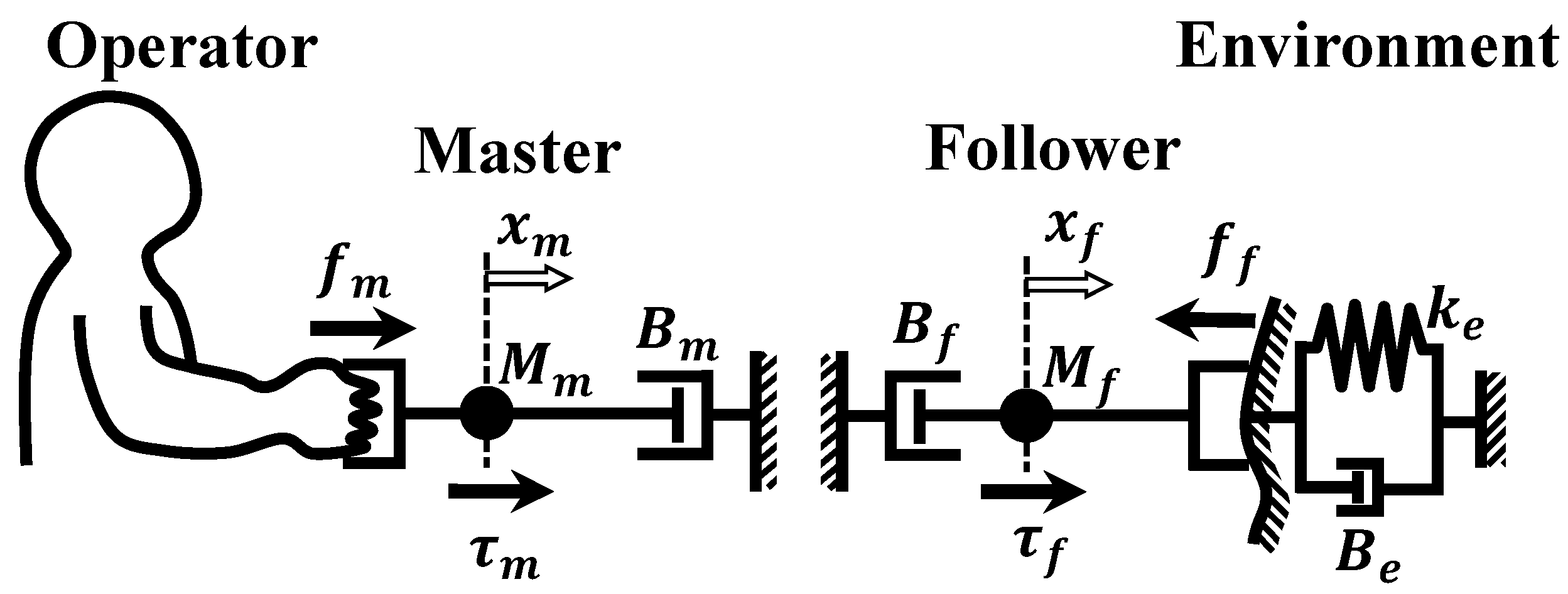
Figure 2.
Block diagram of the force-reflecting bilateral control [39].
Figure 2.
Block diagram of the force-reflecting bilateral control [39].

Figure 3.
Block diagram of the force-projecting bilateral control [39].
Figure 3.
Block diagram of the force-projecting bilateral control [39].

Figure 4.
Step response analysis of the follower reaction force. (a) HARD environment; (b) SOFT environment.
Figure 4.
Step response analysis of the follower reaction force. (a) HARD environment; (b) SOFT environment.

Figure 5.
Step response analysis of the position error between master and follower. (a) HARD environment; (b) SOFT environment.
Figure 5.
Step response analysis of the position error between master and follower. (a) HARD environment; (b) SOFT environment.


Figure 6.
Bode diagram of the force transfer function in numerical simulation. (a) HARD environment; (b) SOFT environment.
Figure 6.
Bode diagram of the force transfer function in numerical simulation. (a) HARD environment; (b) SOFT environment.


Figure 7.
Bode diagram of the position error transfer function in numerical simulation. (a) HARD environment; (b) SOFT environment.
Figure 7.
Bode diagram of the position error transfer function in numerical simulation. (a) HARD environment; (b) SOFT environment.

Figure 8.
One-DOF master-follower manipulator system constructed for the experiment.

Figure 9.
Two types of environmental walls connected by the follower cylinder rod.

Figure 10.
Overall configuration of the experimental apparatus.

Figure 11.
Electrical and pneumatic system diagram of the 1-DOF master-follower manipulator.

Figure 12.
Block diagram of pneumatic servo drive system.

Figure 13.
Frequency response of the pneumatic driving force control.

Figure 14.
Block diagram of the 1-DOF force-reflecting bilateral control implemented into experimental system.
Figure 14.
Block diagram of the 1-DOF force-reflecting bilateral control implemented into experimental system.

Figure 15.
Block diagram of the 1-DOF force-projecting bilateral control implemented into experimental system.
Figure 15.
Block diagram of the 1-DOF force-projecting bilateral control implemented into experimental system.

Figure 16.
Block diagram of the operational force estimator.

Figure 17.
Experimental result of step responses about the forces and positions with two different environments. (Force-Reflecting Type). (a) HARD environment; (b) SOFT environment.
Figure 17.
Experimental result of step responses about the forces and positions with two different environments. (Force-Reflecting Type). (a) HARD environment; (b) SOFT environment.

Figure 18.
Experimental result of step responses about the forces and positions with two different environments. (Force-Projecting Type). (a) HARD environment; (b) SOFT environment.
Figure 18.
Experimental result of step responses about the forces and positions with two different environments. (Force-Projecting Type). (a) HARD environment; (b) SOFT environment.

Figure 19.
Bode diagram of the force transfer function in experiment. (a) HARD environment; (b) SOFT environment.
Figure 19.
Bode diagram of the force transfer function in experiment. (a) HARD environment; (b) SOFT environment.

Figure 20.
Bode diagram of the position error transfer function in the experiment. (a) HARD environment; (b) SOFT environment.
Figure 20.
Bode diagram of the position error transfer function in the experiment. (a) HARD environment; (b) SOFT environment.


Figure 21.
Scene of the master-follower manipulation experiment.

Figure 22.
Experimental result of master-follower operation by human (Force-Reflecting Type). (a) HARD environment; (b) SOFT environment.
Figure 22.
Experimental result of master-follower operation by human (Force-Reflecting Type). (a) HARD environment; (b) SOFT environment.


Figure 23.
Experimental result of master-follower operation by human (Force-Projecting Type). (a) HARD environment; (b) SOFT environment.
Figure 23.
Experimental result of master-follower operation by human (Force-Projecting Type). (a) HARD environment; (b) SOFT environment.

Figure 24.
Comparison of equivalent block diagrams of the force transfer function .


Table 1.
Symbols and Indices.
| Description | Symbol and Index |
|---|---|
| Laplace operator | s |
| Position | |
| Operational force at master | |
| Reaction force at follower | |
| Driving force | |
| Mass | M |
| Spring constant | k |
| Damping coefficient | B |
| Position gain | |
| Velocity gain | |
| Natural frequency | |
| Damping ratio | |
| Index of master | |
| Index of follower |
Table 2.
Transfer functions of block diagrams.
| Meaning | Transfer Function |
|---|---|
| Master impedance | |
| Follower impedance | |
| Master position controller | |
| Follower position controller | |
| Environment impedance | |
| Pneumatic delay |
Table 3.
Parameters used for numerical analyses.
| Side | Coefficient | Symbol | Value | |
|---|---|---|---|---|
| Master | Mass | 0.676 | [kg] | |
| Damping | 3.84 | [Ns/m] | ||
| Position gain | 20.0 | [N/mm] | ||
| Velocity gain | [Ns/mm] | |||
| Follower | Mass | 0.125 | [kg] | |
| Damping | 11.5 | [Ns/m] | ||
| Position gain | LOW Gain: 0.30 | [N/mm] | ||
| MID Gain: 5.0 | [N/mm] | |||
| HIGH Gain: 20.0 | [N/mm] | |||
| Velocity gain | [Ns/mm] | |||
| Environment | Spring constant | HARD: 97.4 | [N/mm] | |
| SOFT: 1.48 | [N/mm] | |||
| Damping ratio | HARD: 0.174 | [-] | ||
| SOFT: 0.249 | [-] | |||
| Damping | [Ns/m] | |||
| Pneumatic | Natural frequency | 39.6 | [Hz] | |
| Damping ratio | 2.36 | [-] |
Table 4.
Main components of the master-follower experimental system.
| Master | Linear motor | Maker | GMC Hillstone Co., Ltd., Yamagata, Japan |
| Model | s160Q | ||
| Stroke | 100 mm | ||
| Rated thrust | 20 N | ||
| Mass of moving part | 0.676 kg | ||
| Motor driver | Maker | Panasonic Corp., Osaka, Japan | |
| Model | MINAS-A6L | ||
| Linear encoder | Maker | Technohands Co., Ltd., Kanagawa, Japan | |
| Model | TAi-200 | ||
| Position resolution | 1.0 m | ||
| Follower | Air cylinder | Maker | SMC Corp., Tokyo, Japan |
| Model | CJ2XE16-100Z | ||
| Bore | 16 mm | ||
| Stroke | 100 mm | ||
| Actuation type | Double acting | ||
| Mass of moving part | 0.125 kg | ||
| Servo valve | Maker | Festo AG & Co. KG, Esslingen, Germany | |
| Model | MPYE-5-M5-010-B | ||
| Pressure sensor | Maker | SMC Corp., Tokyo, Japan | |
| Model | PSE540A-R04 | ||
| Linear encoder | Maker | Technohands Co., Ltd., Kanagawa, Japan | |
| Model | TAi-200 | ||
| Position resolution | 1.0 m |
Table 5.
Parameters for the pneumatic force controller.
| Parameter | Symbol | Value | |
|---|---|---|---|
| Proportional gain | 0.12 | [V/N] | |
| Integral gain | 1.49 | [V/Ns] | |
| Cut-off frequency | 50.0 | [Hz] |
Table 6.
Parameters applied to the experiment system (Force-Reflecting Type).
| Feedback control gains: | |||
| Follower position gain | 0.30 | [N/mm] | |
| Follower velocity gain | 0.38 | [Ns/mm] | |
| Proportional gain of pneumatic drive force | 0.12 | [V/N] | |
| Integral gain of pneumatic drive force | 1.49 | [V/Ns] | |
| Follower inverse dynamics parameters: | |||
| Damping coefficient | 11.5 | [Ns/m] | |
| Coulomb friction force | 1.0 | [N] | |
| Cut-off frequencies: | |||
| Master pseudo-differentiation | 20 | [Hz] | |
| Follower pseudo-differentiation | 20 | [Hz] | |
| Valve command voltage | 50 | [Hz] |
Table 7.
Parameters applied to the experiment system (Force-Projecting Type).
| Feedback control gains: | |||
| Master position gain | 20.0 | [N/mm] | |
| Master velocity gain | 7.35 | [Ns/mm] | |
| Proportional gain of pneumatic drive force | 0.12 | [V/N] | |
| Integral gain of pneumatic drive force | 1.49 | [V/Ns] | |
| Master inverse dynamics parameters: | |||
| Mass of the moving part | 0.676 | [kg] | |
| Damping coefficient | 3.84 | [Ns/m] | |
| Cut-off frequencies: | |||
| Master pseudo-differentiation | 300 | [Hz] | |
| Follower pseudo-differentiation | 20 | [Hz] | |
| Operational force estimator | 100 | [Hz] | |
| Valve command voltage | 50 | [Hz] |
Disclaimer/Publisher’s Note: The statements, opinions and data contained in all publications are solely those of the individual author(s) and contributor(s) and not of MDPI and/or the editor(s). MDPI and/or the editor(s) disclaim responsibility for any injury to people or property resulting from any ideas, methods, instructions or products referred to in the content. |
© 2024 by the authors. Licensee MDPI, Basel, Switzerland. This article is an open access article distributed under the terms and conditions of the Creative Commons Attribution (CC BY) license (https://creativecommons.org/licenses/by/4.0/).
Share and Cite
MDPI and ACS Style
Haraguchi, D.; Monden, R. Fundamental Study on Force-Projecting Bilateral Control for Pneumatically Driven Follower Device. Actuators 2024, 13, 56. https://doi.org/10.3390/act13020056
AMA Style
Haraguchi D, Monden R. Fundamental Study on Force-Projecting Bilateral Control for Pneumatically Driven Follower Device. Actuators. 2024; 13(2):56. https://doi.org/10.3390/act13020056
Chicago/Turabian StyleHaraguchi, Daisuke, and Rin Monden. 2024. "Fundamental Study on Force-Projecting Bilateral Control for Pneumatically Driven Follower Device" Actuators 13, no. 2: 56. https://doi.org/10.3390/act13020056
Note that from the first issue of 2016, this journal uses article numbers instead of page numbers. See further details here.