
Active Edgewise Blade Damping Control of Large Wind Turbines by Using the Pitch Controller and an Interval Observer


1
Institut für Physik, Carl von Ossietzky University of Oldenburg, 26129 Oldenburg, Germany
2
Fraunhofer Gesellschaft, zur Förderung der Angewandten Forschung e. V., 27572 Bremerhaven, Germany
*
Author to whom correspondence should be addressed.
Actuators 2024, 13(2), 58; https://doi.org/10.3390/act13020058
Submission received: 30 November 2023
/
Revised: 30 January 2024
/
Accepted: 1 February 2024
/
Published: 3 February 2024
(This article belongs to the Section Control Systems)
Abstract
:Large wind turbines have typically poorly damped structures. Hence, the absence of damping leads to aeroelastic oscillations, and the operational rotor speed can approach the critical rotor speed. By using damping injection, the control system can actively introduce some additional damping. In the present work, a control approach to reduce oscillations of the rotor blades in the edgewise direction is proposed. The concept is based on the damping injection mechanism, and an additional level of safety is obtained by introducing the Dynamic Safety Margin (DSM) in the control law. The feedback control scheme requires some unmeasurable variables. This aspect is covered by using an interval observer. The control approach is tested by using simulations on a high-definition model implemented in an aeroservoelastic code. Simulation results are very satisfactory and promising for future experiments using hardware-in-the-loop equipment.
1. Introduction
Very large, three-bladed, horizontal-axis, variable-speed, pitch-regulated wind energy systems are typically weakly damped structures, where the primary damping is contributed by aerodynamic forces. Thus, the absence of damping, which could cause blade classic flutter as soon as the operational rotor speed goes close to the critical rotor speed, is frequently the source of the aeroelastic oscillations that can occur in these machines. On the other hand, other vibrations of different types can also be manifested when the machine is operating at its rated wind speed but close to the stall region [1] or when edgewise and torsion blade deformations couple in the presence of significant flapwise blade deflection [2].
The frequent occurrence of vibrations during the operation of very large wind turbines is a direct consequence of the fact that structural optimisation yields blades that are lighter and thinner, increasing their flexibility and making them more prone to vibrating. These mechanical vibrations can not only affect the lifetime of the machine by increasing material fatigue, but, as pointed out in [3], they can also induce vibrations in the electrical system, which can result in a drop in generated power or, even more undesirably, produce over-voltages that cause the wind turbine to be disconnected from the grid. Contrarily, faults in the electrical network may induce mechanical oscillations on the blades and tower [4].
Blade vibrations can be induced in the blade in the flapwise as well as in the edgewise direction. The flapwise and longitudinal tower modes of such machines exhibit substantial aerodynamic damping, and therefore, the vibrations are less critical. On the other hand, the damping of blade modes in the edgewise direction, the torsional modes of the drivetrain, as well as the side-to-side modes of the tower, are often minor leading to important oscillations [1,5]. This can lead to instability. This happens, for instance, when the aerodynamic forces add energy to the blades, exciting the edgewise modes. In this situation, the resulting sum of aerodynamic and structural damping becomes negative [6].
In order to reduce structural vibrations, many approaches have been studied in the past (see, e.g., [7] for a review), and they can be grouped into two main categories: using some kind of damper or special actuators like tendons, and using active damping control.
Damper-based systems are very common and can also be classified as active, semi-active, or passive devices. Passive damping is usual for tower oscillations (see [8,9,10,11,12]).
The use of dampers in the blades is less common, and the dynamic consequences of this needs more research. In particular, studies on the damping of flapwise modes have been little reported, both for semi-active systems [13] and for active systems (combined with tower damping) [14]. Also, in [15], active tendon control and passive pitch control are used together as a dual approach in order to dissociate the power control from the vibration control. Vibrations in both edgewise and flapwise directions are considered.
More common is the use of dampers for edgewise vibrations (see, e.g., [5] for active systems, [16,17] for passive systems, and [18] for semi-active systems. In addition, a shunt damping approach is presented in [19] (see [20] for a review on shunt damping vibration control).
Active damping control has been used in aeronautics for a very long time. For details, the reader is referred to [21]. This concept is based on artificial damping injection, which has its origins in robotics [22] and is also applied with some frequency for the damping of tower modes [9,23,24,25,26,27,28,29].
The application of control-based reduction in blade vibrations is more difficult to find in the literature. Robust H2 control is applied in [30], and a double-pitched blade approach is proposed in [31]. In [32], several controllers (blade damping, LQG, H∞, and improved LQG) are designed and compared for flapwise and edgewise vibrations.
The present work has its roots in an example presented in [33], where the concept of active blade tip deflection damping control (ABDC) in the edgewise direction has been proposed. Thus, a control system to attenuate blade vibrations in the first edgewise mode is suggested. The main idea is to add a new blade damping control feature by adding an extra control loop to the standard collective pitch control system that is used for full-load operation. In order to introduce an additional level of safety, the Dynamic Safety Margin (DSM) is applied to the controller (see, e.g., [34]).
The controller is based on the damping injection concept, which requires knowledge of the edgewise tip deflection of the blade. Since the tip deflection is normally unknown, a structural model for the rotating subsystem is developed and used to design an interval observer for estimating a collective edgewise blade tip deflection.
The interval observer gains are obtained by pole placement, where the particular structure of the system matrix is exploited to accelerate the runtime redesign. Finally, a full-state feedback pitch controller uses the state estimates not only for the regulation generator speed but also for the blade damping control.
The derivation of the control law is carried out in Section 2, which includes not only the pitch controller but also the fundamentals of the damping injection control. Section 3 is devoted to the observer design for a model that also includes a collective edgewise tip deflection. A numerical study based on the simulation of a 20 MW reference wind turbine and the analysis of the corresponding results is the subject of Section 4. Finally, the conclusions are drawn in Section 5.
2. Control Law Derivation
2.1. The Control Problem
In full-load operation, the control system is normally implemented by using a regulator that keeps the rotational speed constant for all wind speeds between the rated value and the cut-out value. The control signal, which is applied to all pitch actuators, is the pitch angle (pitch demand), and the feed-backed signal is the generator rotational speed. The rated generator rotational speed serves as the set-point (see [35] for a review). The main challenge is that very few inputs (only the three blade pitch actuators) are available for all control functions, so different control objectives are normally contradictory, and a compromise is required.
2.2. Active Damping Control
The damping injection controller, which was proposed in the area of robotic manipulators and is founded on the energy shaping principle and passivity control, constitutes the basis for the active damping control approach (see, e.g., [22,36,37]). The idea is to introduce an additional artificial damping component in the control law. This is implemented as a further velocity-proportional feedback loop. Hence, a classic control law can be complemented with a second term, i.e.,
where f stands for a typical control law as a function of the control error e(t), Dc is the damping controller’s gain, and is the time derivative of the position variable x(t). Taking as an example a second-order model of a linear oscillating system, whose motion is described by
with control signals u(t) as the actuating force, M as mass, D as damping, and K as stiffness, the natural frequency and the damping ratio are given by ωn = (K/M)0.5 and ζ = 0.5 D/(M K)0.5, respectively. For an impulse or step signal u(t), the attenuation is dominated by the exponential factor e−ζ ωn t = e−0.5 (D/M) t. On the other hand, it is clear from combining (1) and (2) that the damping coefficient changes to (D + Dc) if u(t) is described by (1).
The control law can also provide a further characteristic by introducing the feedback of the position, i.e.,
This means a change in the stiffness coefficient, which leads in turn to a variation of the natural frequency ωnc = [(K + Kc)/M]0.5. The natural frequency and the damping ratio of the closed loop can now be formulated as
and the damping exponent is
where γK = Kc/K and γD = Dc/D. Hence, changing the stiffness coefficient does not affect the damping characteristic, but it allows the natural frequency to be adjusted to a value more convenient for the system, avoiding, for instance, being too close to the external exciting frequencies.
If the set-points for x(t) and are assumed to be zero, then the last term of (3) corresponds to an ideal PD controller (proportional derivative), whose most important properties are precisely the increase in the damping factor without changing the steady-state and the speeding up of the transient behaviour [38].
2.3. Collective Pitch Control Loop
The control in the full-load operation is carried out by a very complex control system, whose most important component is the collective pitch control scheme (CPC). All other control subsystems are built around the CPC and complement it. This control law can be described by a generic function like
where f represents a function of the control error e(t). A typical control function for the CPC could be the PI controller (proportional, integral) [39,40], which is given by
Kp and Ki are the controller parameters that have to be tuned by the designer. The PI controller also requires an anti-windup mechanism for the integrator. Moreover, the controller needs to adjust the parameters because of the nonlinear behaviour of the system. The classic approach is based on a gain-scheduling approach. There are several procedures to derive the adaptation law (see, for instance, [41,42]). Here, the procedure based on pole placement, as proposed in [43], is used. The design leads to the controller parameters Kp and Ki, which are adapted by using the power sensibility function as a scheduling parameter, i.e.,
where Pm is the mechanical power.
In the next subsections, the damping injection mechanism is applied to augment the damping coefficients of the tower and the blades of wind turbines.
2.4. Active Tower Damping Control
The active tower damping control (ATDC) is designed to reduce the fore–aft oscillations of the tower-top motion of a wind turbine, which are caused by the CPC. The design is based on the damping injection concept (see Section 2.2). The equation of motion (2) can be rewritten in order to represent the fore–aft motion of the tower-top displacement as
where Ft is the thrust force generated by the wind acting on the rotor and x(t) is the tower-top deflection. A variation ∆β in the pitch angle causes a disturbance ∆Ft in the thrust force, which can be formulated by
where ∆β is now compensated by using the control law similar to (3), namely,
Hence, the active tower damping control law is obtained as
with ∂Ft/∂β as the sensitivity function of the thrust force with respect to the pitch angle at the operating point β0. It serves as a scheduling parameter to adapt the controller in response to operating point changes. For Ktc = 0, the control law proposed in [44] is obtained.
2.5. Active Blade Damping Control
The damping injection method has been suggested in [33] as a way to reduce edgewise blade vibrations. Otherwise, there are no reports of this strategy for blade vibration control in the literature.
The idea is based on a dynamic model of motion for the rotor and the low-speed shaft similar to that proposed in [45]. The whole model consisting of four differential equations is developed in [46], and the first of them is given by
where ωr, ωb, θb − θr, and ∆Ta are the rotor angular speed, the angular speed of the blade tip, the tip deflexion angle, and the resulting torque applied to the first mass consisting primarily of the aerodynamic torque, respectively (see Figure 1).
Moreover, Jb, Db, and Kd are, respectively, the joint moment of inertia of the three blade tips, the effective blade damping, and the effective blade stiffness.
The design procedure is the same as that used for active tower damping control, where a variation ∆β on the pitch angle also produces a disturbance ∆Ta on the aerodynamic torque, which is represented by
where ∆Ta(t) is a simplified notation of ∆Ta[β(t)]. The compensation by a PD control law leads to
and consequently to
with ∂Ta/∂β as the sensitivity function of the aerodynamic torque regarding the pitch angle at the operating point β0. It is then the scheduling parameter for the adaptation law. Dbc and Kbc are the controller gains, which have to be chosen by design. Since the interest is focused on the damping, Kbc can be set to zero. The active increasing of the damping cannot be arbitrary but limited. Assuming an increasing factor γ, e.g., γ = 0.1, for 10%, the controller gain can be calculated by Dbc = γ Db.
2.6. Pitch Control System with Active Damping Control
The pitch control system, including all active damping controllers, is portrayed in Figure 2, where the interaction between CPC, ATDC, and ABDC is evident since all three controllers are combined into a single control signal. In the diagram, only derivative controllers are considered for simplicity.
The control system requires a compromise between all controllers in order to operate correctly since the CPC reacts strongly to increasing turbulence, which results in oscillations with higher amplitudes for the tower and blades. On the other hand, active damping controllers reduce the fluctuations by modifying the pitch angle, working against the CPC.
A solution to this kind of compromise is provided in [27]. It considers the control system as a cooperative game, with the controllers as players. For the current design, the CPC is chosen as one player, while the second player is a team constituted by all active damping controllers. The game is solved by using parametric multi-objective Pareto optimisation in order to tune all controllers together and a decision maker (see [47] for a survey) to choose one solution from the Pareto front. As payoffs for the game, the performance indices
are used. Variables ωg and are the only measurable variables. can be obtained by integrating . Thus, a dynamic model and a state observer are necessary to estimate the other variables.
2.7. Application of the Dynamic Safety Marging
The goal of the Dynamic Safety Margin (DSM) approach, which was first presented in [34,48,49,50], is to enable the optimal operation of a technical system without going beyond the plant’s safety limitations. The method has been successfully tested with process engineering systems. However, despite its simplicity, it has not yet been implemented with wind turbines. The DSM is defined here as the instantaneous shortest distance δ(t) between the state vector of interest and a predefined safety boundary function φ(x), as shown in Figure 3, where the state trajectory begins at x0 and ends at xss.
Now, the idea is put forth in the manner that follows. The DSM is expressed by
where is the shortest distance from x(t) to φ(x). The inside of the safety region is characterised by φ(x) < 0, the outside by φ(x) > 0, and the limit by φ(x) = 0. s(t) is a binary function defined by
The formulation of a proportional gain, including the DSM, is presented in [51]. It is first formulated as
and an alternative formula is also proposed as
3. Estimation of State Variables
3.1. Observer-Based Estimation of State Variables
The use of observers for the estimation of the state variables of linear systems goes back many years, when the Luenberger observer [48] and the Kalman filter [49] were proposed for deterministic and stochastic systems, respectively. Later, state observers evolved in different directions. For instance, a particular approach is the observer with unknown input (see, e.g., [50,52]). The nonlinear case has also been extensively studied [53,54,55,56].
One drawback of these approaches is that they require accurate parametric models, a requirement that is typically unsatisfactory in practice due to parametric uncertainties [57]. To overcome this obstacle, [58] proposes a robust observer design. Interval mathematics-based methods are another way of addressing the issue of uncertain dynamic systems [59]. This concept is the basis of an interval Kalman filter, which is proposed in [60], and an observer in [61,62]. Observability aspects of interval systems are given in [63], and a comparison between several observer configurations is carried out in [64].
The literature contains a relatively large number of observer-based approaches to wind turbine estimation and control. An important application for observers is the estimation of the effective wind speed. This is the case presented in [65,66], where an observer with unknown input combined with a PI controller is used for the joint estimation of the effective wind speed and the aerodynamic torque. In [67], an observer is used to estimate the power coefficient. Observers are also used in [67,68] for fault detection and fault-tolerant control. An observer-based pitch control system for disturbance rejection is presented in [69]. In [70], a Kalman filter is used to estimate several variables, including the edgewise tip deflection. Extended Kalman filters are particularly designed for nonlinear estimation, and in [33], an extended Kalman filter is combined with a six-order dynamic model and a disturbance observer. The present development follows the adaptive interval observer proposed in [71].
3.2. Mathematical Description of the Dynamic System
A dynamic model of the rotor that includes variables related to the blades, like ωb and θb, is not simple. In this work, the model derived in [72] by using hinge points is used. It comprises the collective edgewise blade tip deflection and torsional characteristics of both shafts, as shown in Figure 4. In this case, it is a linear model that should cover the whole range of wind speed variation in Region III, i.e., some of the parameters are not constant. However, for the variable parameters, finite intervals of variation can be set, and therefore it is an interval model leading to an interval observer. The model development process follows the abstraction process described in Figure 4 (see [47,73]).
Interval parameters Jb_root, Db, Kb, Bxl and Bxh depend on inputs and steady-state values, which also depend on the wind speed within a determined range. Therefore, the state space model can be represented by the equations
where u1 = Ta, u2 = Tg and y = ωg, and the matrices are given by
with Jbe = 3 Jb_tip, Jhe = Jh + 3 Jb_root, Jge = Jxl + nx2 Jxh, and Be = Bxl + Dlss + nx2(Bxh+Dhss). The notation A(x, u1, u2) indicates the dependence of the same parameters of A with respect to the inputs and states, as previously mentioned. The complete notation is explained in Table 1, Table 2 and Table 3.
3.3. Observer Design with Effective Wind Speed Estimation
The observer is inspired by the idea of an observer with unknown input [74], which is used in [75] to estimate the effective wind speed. The most important difference is that the model is time-varying with interval parameters. Therefore, the observer needed here must be adaptive to these types of parameters, a feature that is achieved by using a frozen time strategy [76]. This leads to the concept of an interval observer with unknown input (see, for example, [72,77]).
The unknown input for the observer is the aerodynamic torque. It can be estimated by using a PI controller, where the controller input is the error computed as the difference between the measured and estimated generator rotational speeds (see Figure 5).
In order to adapt the observer, it is necessary to set the current values of the model parameters, which depend on the effective wind speed. However, the effective wind speed is also not a measured variable. However, the observer can be extended in order to obtain a similar configuration as proposed in [75] for the estimation of the effective wind speed. The extension that was mentioned above consists of a Newton–Raphson algorithm to find the value of the tip-speed ratio λ that satisfies the function
and the calculation of the effective wind speed by using
The still-undefined parameters are ρa as the air density, R as the rotor radius, and Cp as the power coefficient. The whole block diagram is schematized in Figure 6.
The observer design is carried out by using the pole placement method according to the algorithm proposed in [78]. Thus, all poles of the observer assigned by means of P(s) and obtained from
are always maintained in the same position by recalculating ko according to the changes produced on A. The observer design for linear time-invariant (LTI) systems requires the observability of the pair (A, cT). However, the matrix A is not constant, and therefore the observability condition is more complex.
4. Numerical Study
The efficacy of the proposed control approach is illustrated by a numerical example using a 20 MW reference wind turbine. This reference wind turbine was first proposed in [79] and has been modified and studied for modelling and control in [72,80].
The simulation experiments of the reference wind turbine are carried out using OpenFAST v. 3.5.1 (formerly known as FAST) [81], and the control system is implemented in MATLAB 7.0® and Simulink®.
4.1. Parameters and Rated Values
By combining known parameters, simulation data, steady-state conditions, and optimisation, a grey-box approach is achieved in order to parametrize the matrices (25). Parameters can be summarised in three subsets: rated values (Table 1), known parameters of the wind turbine (Table 2), and computed interval parameters (Table 3).
Finally, numerical values for the sensitivity functions are required.
4.2. Sensitivity Functions
The previously developed control laws require three different sensibility functions, ∂Pm/∂β, ∂Ft/∂β, and ∂Ta/∂β, all evaluated at the operating point β0, which in turn depends on the effective wind speed. Assuming that Pm and Ft are outputs of a nonlinear system whose input is β. The linearization process yields
Thus, the partial derivatives are obtained by means of the linearization process for each value of the effective wind speed. The aerodynamic torque under pitch control can be computed from Ta = Pm/(nx ωg,rated), and in this case, it follows
4.3. Experiments for the Simulation Environment
Simulation experiments in a carefully prepared simulation environment are used to investigate the design of the pitch control system. The wind turbine is operated in Region III.
In order to appreciate the blade oscillations and the effects of the control system, a piecewise constant wind speed profile varying between 12 and 22.5 m/s is used. The simulation time is limited to 600 s, and the controller is operated only under the CPC. Hence, simulations are repeated with the ABDC switched on.
4.4. Observer Performance
The interval observer was preliminarily studied in [71]. Therefore, the results are included here for the sake of completeness and to show that the observer performance is satisfactory in order to use it for control purposes. The mission of the observer is to estimate unmeasurable variables, which in the present case are the effective wind speed, the aerodynamic torque, and the collective tip deflection of blades. The quantitative analysis is summarised in Table 4, where the cross-correlation functions and root-mean-square errors show satisfactory numbers for all estimated variables of interest.
A qualitative appreciation of the observer’s performance can be extracted from Figure 8.
4.5. Simulation Results and Analysis
The control system design is carried out twice. In the first one, only parameters for the CPC working as a unique controller are tuned. This controller is used as a reference. The second design is obtained by Pareto optimisation of (17) and (18) in order to jointly find the parameters for the CPC and the ABDC. Moreover, the DSM is included as a hard constraint in the optimization. All the parameters are summarised in Table 5.
The effective wind speed is assumed to be piecewise constant with corner points (0 s, 16.5 m/s; 150 s, 22.5 m/s; 250 s, 15.5 m/s; 350 s, 12.5 m/s) to cover a simulation of 600 s. The wind profile is included in the simulation figures, with the axis on the right. The limit for a maximum allowed deflection was 1.2 m from the rest position set at the pitch axis. Because of the definition of the coordinate system, deflections in the wind direction are considered negative. Hence, improvements in the performance of the blade damping control correspond to simulation curves closer to the zero axis, as can be observed in the blue curve in relation to the black one in Figure 9. Thus, the damping increase corresponds to an average reduction in the deflection of 13%. This reduction means that the maximum deflection of the blades, which can exceed the safety limit in the case of strong wind and the CPC working alone, is now below this bound, leaving an active range for the work of the DSM.
The inclusion of the ABDC introduces differences in the power conversion. Hence, a compromise in the design of both control systems has to be found. In the case of the machine here, the difference is not significant. This can be appreciated in Figure 10. The energy conversion in the simulation time for the CPC is 2904 kWh, and in the case of the CPC with ABDC, it is 2729, i.e., a loss of 175 kWh.
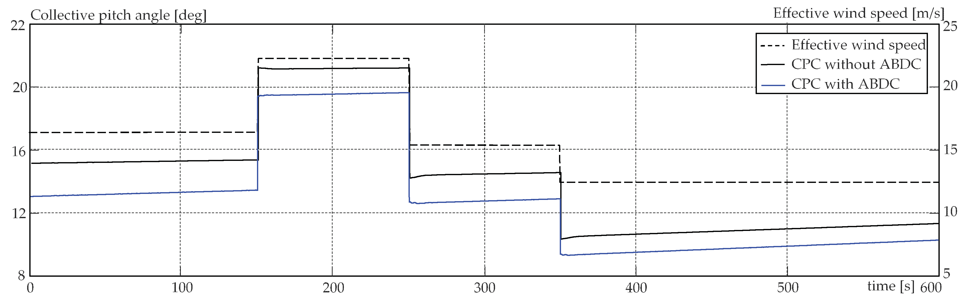
Finally, it is important to analyse the control effort. This corresponds here to the pitch angle. Both control systems provide comfortable control signals that are not particularly demanding for the pitch actuators, despite their differences, as can be observed in Figure 11.
5. Conclusions
Pitch control is necessary for large wind energy conversion systems not only to enable them to operate at high wind speeds but also to ensure a long lifespan. Over the last two decades, numerous control objectives, approaches, and specific methods have been put forth regarding pitch control to address the issues that wind energy technology has presented to the field of control engineering. The present work is a new step in this direction.
Edgewise blade deflections are often not considered in pitch control systems despite their critical importance. Therefore, blade deflections are subjected in the present work to a control system consisting of an active damping control complemented by a safety net provided by the dynamic safety margin approach. Non-measurable variables are estimated by means of an interval observer. The study shows, on the one hand, a consistent development and, on the other hand, very good results with regard to this first analysis.
Additional features of the pitch control systems, such as active tower damping control and individual pitch control, have been deactivated to avoid interference with the new approach and to observe its isolated behaviour. Thus, the next steps in the research will be the gradual inclusion of the switched-off features in the pitch control system and the real-time testing by using the hardware-in-the-loop facility.
Author Contributions
Conceptualization, investigation, writing (first draft preparation), validation, and programming, S.C.; conceptualization, conceptual verification, and writing (review and editing), A.G. All authors have read and agreed to the published version of the manuscript.
Funding
This work has been financed by the Federal Ministry of Economic Affairs and Climate Action (BMWK).
Institutional Review Board Statement
Not applicable.
Informed Consent Statement
Not applicable.
Data Availability Statement
Data are available upon request from the corresponding author if allowed by the funding agency.
Conflicts of Interest
The authors declare no conflicts of interest. The funders had no role in the design of the study, in the collection, analyses, or interpretation of data, in the writing of the manuscript, or in the decision to publish the results.
Abbreviations
| ABDC | Active Blade Damping Control |
| ATDC | Active Tower Damping Control |
| CPC | Collective Pitch Control |
| DSM | Dynamic Safety Margin |
| LQG | Linear Quadratic Gaussian |
| LTI | Linear Time Invariant |
| PD | Proportional Derivative |
| PI | Proportional Integral |
Nomenclature
| Parameters | |
| Bg | Generator viscose friction coefficient, Nm s/rad |
| Be | Equivalent friction coefficient, Nm s/rad |
| Br | Rotor viscose friction coefficient, Nm s/rad |
| Cp | Power coefficient, -- |
| Cp,max | Maximum value of the power coefficient, -- |
| Dlss | Damping coefficient of the low-speed shaft, Nm s/rad |
| Dhss | Damping coefficient of the high-speed shaft, Nm s/rad |
| K | Proportional constant, Nm/(rad/s)2 |
| Klss | Stiffness coefficient for the low-speed shaft, Nm/rad |
| Khss | Stiffness coefficient for the high-speed shaft, Nm/rad |
| Kp, Ki, Ka, Dbc, Kbc | Controller gains |
| Jr | Rotor mass moment of inertia, kg m2 |
| Jg | Generator mass moment of inertia, kg m2 |
| nx | Gearbox ratio, -- |
| Pm,rated | Rated mechanical power, MW |
| R | Rotor radius, m |
| Ta,rated | Rated aerodynamic torque, kg m2 |
| Ta∞ | Steady-state value of the aerodynamic torque, kg m2 |
| Tg,rated | Rated generator torque, kg m2 |
| vci | Cut-in value for the wind speed, m/s |
| vco | Cut-out value for the wind speed, m/s |
| vv,rated | Rated value for the wind speed, m/s |
| ∆θ∞ | Steady-state value for twist angle for the low-speed shaft, rad |
| λ* | Optimal tip-speed ratio |
| ηx, ηg | Efficiency of gearbox and generator |
| ρa | Density of air, kg/m3 |
| ωg,rated | Rated value of the generator speed, rad/s |
| ωr,rated | Rated value of the rotor speed, rad/s |
| ∂Pm/∂β, ∂Ft/∂β, ∂Ta/∂β | Partial derivatives of mechanical power, thrust force, and aerodynamic torque with respect to pitch angle |
| A | System matrix |
| b | Input vector |
| c | Output vector |
| ko | Observer gain |
| aij | Elements of matrix A |
| Variables | |
| Pm | Mechanical power, MW |
| Ta | Aerodynamic torque (on the low-speed shaft), kg m2 |
| Tg | Generator torque (on the low-speed shaft), kg m2 |
| vv | Wind speed, m/s |
| xi | State variables |
| β | Pitch angle, rad |
| β0 | Pitch angle at the operating point, rad |
| Δθ | Twist angle of the low-speed shaft, rad |
| λ | Tip-speed ratio, -- |
| ωg | Generator speed, rad/s |
| ωr | Rotor speed, rad/s |
| Jcpc, Jabdc | Objective factions for control system design |
| e | Control error |
| δ | Dynamic safety margin |
| Functions | |
| f | Controller function |
| φ | Safety boundary delimiter |
| Ψ | Function used to find the tip-speed ratio (Equation (26)) |
References
- Hansen, M.H. Aeroelastic instability problems for wind turbines. Wind. Energy 2007, 10, 551–577. [Google Scholar] [CrossRef]
- Kallesøe, B.S.; Kragh, K.A. Field validation of the stability limit of a multi MW turbine. J. Phys. Conf. Ser. 2016, 753, 042005. [Google Scholar] [CrossRef]
- Jacobson, D.; Laninga, J.; Brandt, R. Wind interconnection in Manitoba. In Proceedings of the CIGRÉ Canada Conference on Power Systems, Montreal, QC, Canada, 1–4 October 2006. [Google Scholar]
- Basu, B.; Staino, A.; Basu, M. Role of flexible alternating current transmission systems devices in mitigating grid fault-induced vibration of wind turbines. Wind. Energy 2014, 17, 1017–1033. [Google Scholar] [CrossRef]
- Staino, A.; Basu, B.; Nielsen, S.R.K. Actuator control of edgewise vibrations in wind turbine blades. J. Sound Vib. 2012, 331, 1233–1256. [Google Scholar] [CrossRef]
- Riziotis, V.A.; Voutsinas, S.G.; Politis, E.S.; Chaviaropoulos, P.K. Aeroelastic stability of wind turbines: The problem, the tethods and the issues. Wind Energy 2004, 7, 373–392. [Google Scholar] [CrossRef]
- Awada, A.; Younes, R.; Ilinca, A. Review of vibration control methods for wind turbines. Energy 2021, 14, 3058. [Google Scholar] [CrossRef]
- Murtagh, P.J.; Basu, B.; Broderick, B.M. Along-wind response of a wind turbine tower with blade coupling. Eng. Struct. 2005, 27, 1209–1219. [Google Scholar] [CrossRef]
- Murtagh, P.J.; Ghosh, A.; Basu, B.; Broderick, B.M. Passive control of wind turbine vibrations including blade/tower interaction and rotationally sampled turbulence. Wind. Energy 2008, 11, 305–317. [Google Scholar] [CrossRef]
- Lackner, M.A.; Rotea, M. Passive structural control of offshore wind turbines. Wind. Energy 2011, 14, 373–388. [Google Scholar] [CrossRef]
- Dinh, V.; Basu, B. Passive control of floating offshore wind turbine nacelle and spar vibrations by multiple tuned mass dampers. Struct. Control Health Monit. 2015, 22, 152–176. [Google Scholar] [CrossRef]
- Mensah, A.F.; Dueñas-Osorio, L. Improved reliability of wind turbine towers with tuned liquid column dampers (TLCDs). Struct Saf. 2014, 47, 78–86. [Google Scholar] [CrossRef]
- Arrigan, J.; Pakrashi, V.; Basu, B.; Nagarajaiah, S. Control of flapwise vibrations in wind turbine blades using semi-active tuned mass dampers. Struct. Control. Health Monit 2011, 18, 840–851. [Google Scholar] [CrossRef]
- Fitzgerald, B.; Basu, B. Active tuned mass damper control of wind turbine nacelle/tower vibrations with damaged foundations. In Proceedings of the 10th International Conference on Damage Assessment of Structures (DAMAS 2013), Dublin, Ireland, 8–10 July 2013; pp. 660–667. [Google Scholar]
- Staino, A.; Basu, B. Emerging trends in vibration control of wind turbines: A focus on a dual control strategy. Philos. Trans. R. Soc. A Math. Phys. Eng. Sci. 2015, 373, 1–16. [Google Scholar] [CrossRef]
- Zhang, Z.L.; Nielsen, S.R.K. Edgewise vibration control of wind turbine blades using roller and liquid dampers. J. Phys. Conf. Ser. 2014, 524, 012037. [Google Scholar] [CrossRef]
- Park, S.; Lackner, M.A. Edgewise vibration suppression of multi-megawatt wind turbine blades using passive tuned mass dampers. Wind. Eng. 2021, 45, 1082–1100. [Google Scholar] [CrossRef]
- Andreasen, R.B. Damping of edgewise vibrations of wind turbine blades by smart liquid dampers. Master’s Thesis, Aalborg University, Aalborg, Denmark, 2017. [Google Scholar]
- Biglari, H.; Fakhari, V. Edgewise vibration reduction of small size wind turbine blades using shunt damping. J. Vib. Control 2020, 26, 186–199. [Google Scholar] [CrossRef]
- Yan, B.; Wang, K.; Hu, Z.; Wu, C.; Zhang, X. Shunt Damping Vibration Control Technology: A Review. Appl. Sci. 2017, 7, 494. [Google Scholar] [CrossRef]
- Livne, E. Aircraft active flutter suppression: State of the art and technology maturation needs. J. Aircr. 2018, 55, 410–450. [Google Scholar] [CrossRef]
- Takegaki, M.; Arimoto, S. A new feedback method for dynamic control of manipulators. J. Dyn. Syst. Meas. Control. 1981, 103, 119–125. [Google Scholar] [CrossRef]
- Bossanyi, E.A. The design of closed loop controllers for wind turbines. Wind. Energy 2000, 3, 149–163. [Google Scholar] [CrossRef]
- Leithead, W.E.; Domínguez, S. Analysis of tower/blade interaction in the cancellation of the tower fore-aft mode via control. In Proceedings of the European Wind Energy Conference, London, UK, 22–25 November 2004; pp. 1–10. [Google Scholar]
- Bossanyi, E.A. Wind turbine control for load reduction. Wind. Energy 2003, 6, 229–244. [Google Scholar] [CrossRef]
- Wright, A.D.; Fingersh, L.J. Advanced Control Design for Wind Turbines; Technical Report; National Renewable Energy Laboratory (NREL): Golden, CO, USA, 2008. [Google Scholar]
- Gambier, A. Simultaneous design of pitch control and active tower damping of a wind turbine by using multi-objective optimization. In Proceedings of the 1st IEEE Conference on Control Technology and Applications, Kohala Coast, Australia, 27–30 December 2017; pp. 1679–1684. [Google Scholar]
- Gambier, A.; Nazaruddin, Y. Collective pitch control with active tower damping of a wind turbine by using a nonlinear PID approach. IFAC Pap. 2018, 51, 238–243. [Google Scholar] [CrossRef]
- Gambier, A.; Nazaruddin, Y. Wind turbine pitch and active tower damping control using metaheuristic multi-objective bat optimization. In Proceedings of the 19th International Multidisciplinary Modeling & Simulation Multiconference, Rome, Italy, 19–21 September 2022; pp. 1–9. [Google Scholar]
- Imran, R.; Hussain, D.; Soltani, M.; Rafaq, R. Optimal tuning of multivariable disturbance-observer-based control for flicker mitigation using individual pitch control of wind turbine. IET Renew. Power Gener. 2016, 11, 1121–1128. [Google Scholar] [CrossRef]
- Chen, B.; Hua, X.; Zhang, Z.; Nielsen, S.R.K.; Chen, Z. Active flutter control of the wind turbines using double-pitched blades. Renew. Energy 2021, 163, 2081–2097. [Google Scholar] [CrossRef]
- Zhou, F.; Yang, J.; Pang, J.; Wang, B. Research on control methods and technology for reduction of large-scale wind turbine blade vibration. Energy Rep. 2023, 9, 912–923. [Google Scholar] [CrossRef]
- Gambier, A. Evolutionary multiobjective optimization with fractional order integral objectives for the pitch control system design of wind turbines. IFAC-Pap. 2019, 52, 274–279. [Google Scholar] [CrossRef]
- Abdel-Geliel, M.; Badreddin, E.; Gambier, A. Dynamic safety margin in fault-tolerant predictive controller. In Proceedings of the 2005 IEEE Conference on Control Applications, Toronto, ON, Canada, 28–31 August 2005; pp. 803–808. [Google Scholar]
- Gambier, A. Pitch control of three bladed large wind energy converters—A Review. Energies 2021, 14, 8083. [Google Scholar] [CrossRef]
- Stramigioli, S. Creating artificial damping by means of damping injection. In Proceedings of the 1996 ASME International Mechanical Engineering Congress and Exposition, Atlanta, GA, USA, 17–22 November 1996; pp. 601–606. [Google Scholar]
- Ortega, R.; Spong, M.W. Adaptive motion control of rigid robots: A tutorial. Automatica 1989, 25, 877–888. [Google Scholar] [CrossRef]
- Åström, K.J.; Hägglund, T. PID Controllers: Theory, Design and Tuning; ISA International Society for Measurement and Control: Research Triangle Park, CA, USA, 1995. [Google Scholar]
- Rundqwist, L. Anti-Reset Windup for PID Controllers; Lund Institute of Technology: Lund, Sweden, 1991. [Google Scholar]
- Arrigan, J.; Huang, C.; Staino, A.; Basu, B.; Nagarajaiah, S. A frequency tracking semi-active algorithm for control of edgewise vibrations in wind turbine blades. Smart Struct. Syst. 2014, 13, 177–201. [Google Scholar] [CrossRef]
- Leith, D.J.; Leithead, W.E. Appropriate realization of gain-scheduled controllers with application to wind turbine regulation. Int. J. Control 1996, 65, 223–248. [Google Scholar] [CrossRef]
- Chen, J.-J.; Ji, Z.-C. The gain scheduling control for wind energy conversion system based on LPV model. In Proceedings of the 2010 International Conference on Networking, Sensing and Control, Chicago, IL, USA, 10−12 April 2010; pp. 653–657. [Google Scholar] [CrossRef]
- Gambier, A. Control of Large Wind Energy Systems; Springer Nature: Basel, Switzerland, 2022; ISBN 978-3-030-84894-1. [Google Scholar]
- Burton, T.; Jenkins, N.; Sharpe, D.; Bossanyi, E. Wind Energy Handbook, 2nd ed.; John Wiley & Sons: Chichester, UK, 2011; ISBN 978-1-119-99271-4. [Google Scholar]
- Melício, R.; Mendes, V.; Catalao, J. Transient analysis of variable speed wind turbines at wind speed disturbances and a pitch control malfunction. Appl. Energy 2011, 88, 1322–1330. [Google Scholar] [CrossRef]
- Gambier, A. Dynamic modelling of the rotating subsystem of a wind turbine for control design purposes. IFAC-Pap. 2017, 50, 9896–9901. [Google Scholar] [CrossRef]
- Gambier, A. Multiobjective optimal control of wind turbines: A survey on methods and recommendations for the implementation. Energies 2022, 15, 567. [Google Scholar] [CrossRef]
- Luenberger, D.G. Observing the state of a linear system. IEEE Trans. Mil. Electron. 1964, 8, 74–80. [Google Scholar] [CrossRef]
- Kalman, R.E. A new approach to linear filtering and prediction problems. J. Basic Eng. 1960, 82, 35–45. [Google Scholar] [CrossRef]
- Hou, M.; Müller, P.C. Design of observers for linear systems with unknown inputs. IEEE Trans. Autom. Control 1992, 37, 871–875. [Google Scholar] [CrossRef]
- Abdel-Geliel, M.; Badreddin, E. Adaptive controller using dynamic safety margin for hybrid laboratory plant. In Proceedings of the American Control Conference, Portland, OR, USA, 8–10 June 2005; pp. 1443–1448. [Google Scholar]
- Moghaddamjoo, A.; Kirlin, R.L. Robust adaptive Kalman filtering with unknown inputs. IEEE Trans. Acoust. Speech Signal Process. 1989, 37, 1166–1175. [Google Scholar] [CrossRef]
- Bernard, P. Observer Design for Nonlinear Systems; Springer: Cham, Switzerland, 2019. [Google Scholar]
- Nijmeijer, H.; Fossen, T.I. New Directions in Nonlinear Observer Design; Springer: Berlin, Germany, 1999. [Google Scholar]
- Kim, P. Kalman Filter for Beginners: With MATLAB Examples; CreateSpace: Scotts Valley, CA, USA, 2011. [Google Scholar]
- Condomines, J.-P. Nonlinear Kalman Filter for Multi-Sensor Navigation of Unmanned Aerial Vehicles; ISTE Press—Elsevier: London, UK, 2018. [Google Scholar]
- Doyle, J.C.; Stein, G. Robustness with Observers. IEEE Trans. Autom. Control 1979, 24, 607–611. [Google Scholar] [CrossRef]
- Akpan, E. Robust observer for uncertain linear systems. In Proceedings of the American Control Conference, Arlington, TX, USA; 2001. [Google Scholar]
- Moore, R.E.; Kearfott, R.B.; Cloud, M.J. Introduction to Interval Analysis; Society for Industrial and Applied Mathematics: Philadelphia, PA, USA, 2009. [Google Scholar]
- Chen, G.; Wang, J.; Shieh, L.-S. Interval Kalman filtering. IEEE Trans. Aerosp. Electron. Syst. 1997, 33, 250–259. [Google Scholar] [CrossRef]
- Efimov, D.; Raïssi, T. Design of interval observers for uncertain dynamical systems. Autom. Remote Control. 2016, 77, 191–225. [Google Scholar] [CrossRef]
- Cacace, F.; Germani, A.; Manes, C. A new approach to design interval observers for linear systems. IEEE Trans. Autom. Control 2015, 60, 1665–1670. [Google Scholar] [CrossRef]
- Wang, K.; Michel, A.N. Necessary and sufficient conditions for the controllability and observability of a class of linear, time-invariant systems with interval plants. IEEE Trans. Autom. Control 1994, 39, 1443–1447. [Google Scholar] [CrossRef]
- Ritter, B.; Schild, A.; Feldt, M.; Konigorski, U. The design of nonlinear observers for wind turbine dynamic state and parameter estimation. J. Phys. Conf. Ser. 2016, 753, 1–12. [Google Scholar] [CrossRef]
- Odgaard, P.F.; Damgaard, C.; Nielsen, R. Unknown input observer based estimation of wind speed for wind turbines control. In Proceedings of the IFAC World Congress, Milan, Italy, 28 August–2 September 2011. [Google Scholar]
- Odgaard, P.F.; Stoustrup, J. Fault tolerant wind speed estimator used in wind turbine controllers. In Proceedings of the 8th IFAC Symposium on Fault Detection, Supervision and Safety of Technical Processes, Mexico City, Mexico, 29–31 August 2012; pp. 331–336. [Google Scholar]
- Odgaard, P.F.; Damgaard, C.; Nielsen, R. On-line estimation of wind turbine power coefficients using unknown input observers. In Proceedings of the 17th IFAC World Congress, Seoul, Republic of Korea, 6–11 July 2008. [Google Scholar]
- Odgaard, P.F.; Stoustrup, J. Unknown input observer based scheme for detecting faults in a wind turbine converter. In Proceedings of the 7th IFAC Symposium on Fault Detection, Supervision and Safety of Technical Processes, Barcelona, Spain, 30 June–3 July 2009. [Google Scholar]
- Yuan, Y.; Chen, X.; Tang, J. Disturbance observer based pitch control of wind turbines for disturbance rejection. In Proceedings of the Smart Materials and Nondestructive Evaluation for Energy Systems, Las Vegas, NV, USA, 21–23 March 2016. [Google Scholar]
- Ritter, B.; Konigorski, U. Advanced multivariable control design for modern multi-MW wind turbines. In Proceedings of the 11th EAWE PhD Seminar on Wind Energy in Europe, Stuttgart, Germany, 23–25 September 2015. [Google Scholar]
- Chamoli, S.; Gambier, A. Adaptive interval observer design with application to wind energy converters. In Proceedings of the 20th International Conference on Control, Automation and Systems (ICCAS), Busan, Republic of Korea, 13–16 October 2020; pp. 350–355. [Google Scholar] [CrossRef]
- Chamoli, S.; Gambier, A. Modelling, parametrization and observer design of a 20 MW reference wind turbine for control purposes. J. Phys. Conf. Ser. 2020, 1618, 022031. [Google Scholar] [CrossRef]
- Ramtharan, G.; Anaya-Lara, O.; Bossanyi, E.; Jenkins, N. Influence of structural dynamic representations of FSIG wind turbines on electrical transients. Wind. Energy 2007, 10, 293–301. [Google Scholar] [CrossRef]
- Darouach, M.; Zasadzinski, M.; Xu, S.J. Full-order observers for linear systems with unknown inputs. IEEE Trans. Autom. Control 1994, 39, 607–609. [Google Scholar] [CrossRef]
- Østergaard, K.Z.; Brath, P.; Stoustrup, J. Estimation of effective wind speed. J. Phys. Conf. Ser. 2007, 75, 012082. [Google Scholar] [CrossRef]
- Tóth, R. Modeling and Identification of Linear Parameter-Varying Systems, 1st ed.; Springer: Berlin, Germany, 2010. [Google Scholar]
- Gambier, A.; Nazaruddin, Y.Y. Modelling the wind turbine by using the tip-speed ratio for estimation and control. Energies 2022, 15, 9454. [Google Scholar] [CrossRef]
- Kautsky, J.; Nichols, N.K.; Van Dooren, P. Robust pole assignment in linear state feedback. Int. J. Control. 1985, 41, 1129–1155. [Google Scholar] [CrossRef]
- Ashuri, T.; Martins, J.R.R.A.; Zaaijer, M.B. Aeroservoelastic design definition of a 20 MW common research wind turbine model. Wind. Energy 2016, 19, 2071–2087. [Google Scholar] [CrossRef]
- Gambier, A.; Meng, F. Control system design for a 20 MW reference wind turbine. In Proceedings of the 12th Asian Control Conference, Hong Kong, 19–21 August 2019; pp. 258–263. [Google Scholar] [CrossRef]
- Jonkman, J.; Jonkman, B. FAST modularization framework for wind turbine simulation: Full-system linearization. J. Phys. Conf. Ser. 2016, 753, 082010. [Google Scholar] [CrossRef]
Figure 1.
Frontal scheme of the rotor showing the deflections of the blade tips.
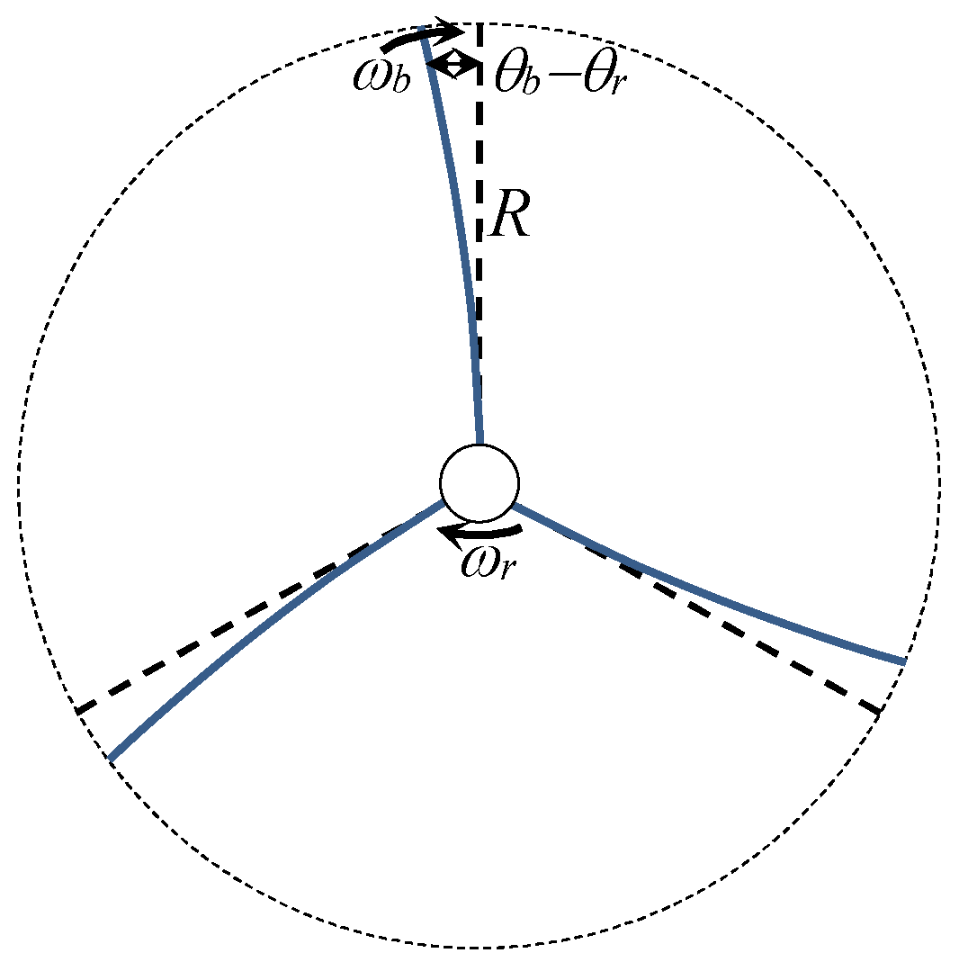
Figure 2.
Configuration of the control system, including active tower and blade damping control loops.
Figure 2.
Configuration of the control system, including active tower and blade damping control loops.
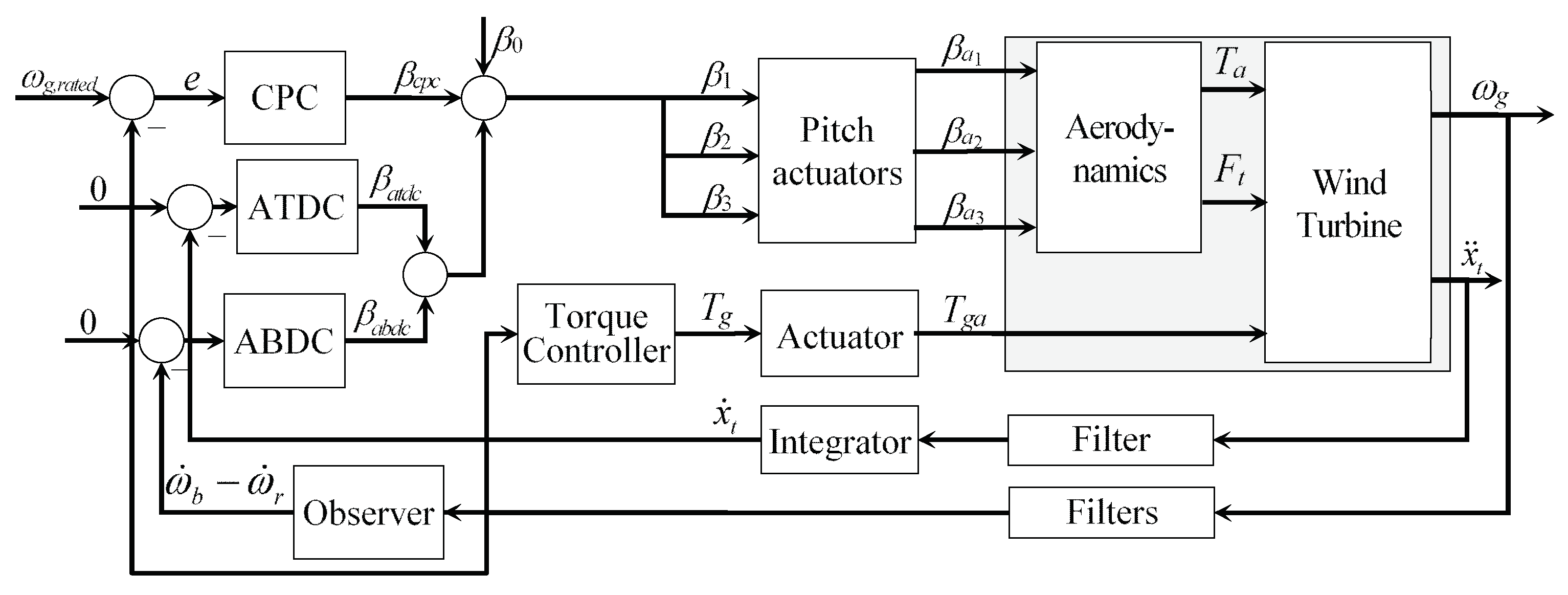
Figure 3.
Definition of the DSM.
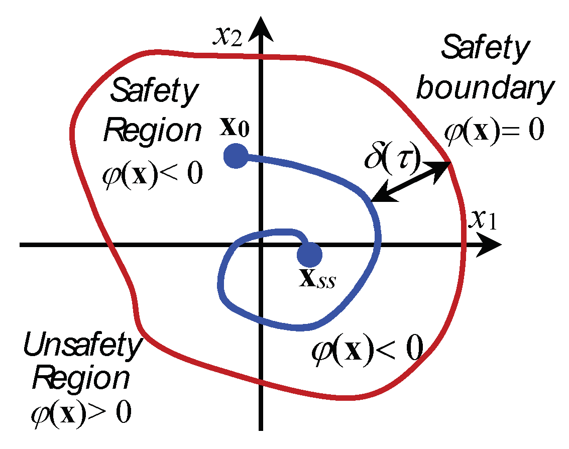
Figure 4.
Modelling scheme for a rotor representation based on two masses [72].
Figure 4.
Modelling scheme for a rotor representation based on two masses [72].
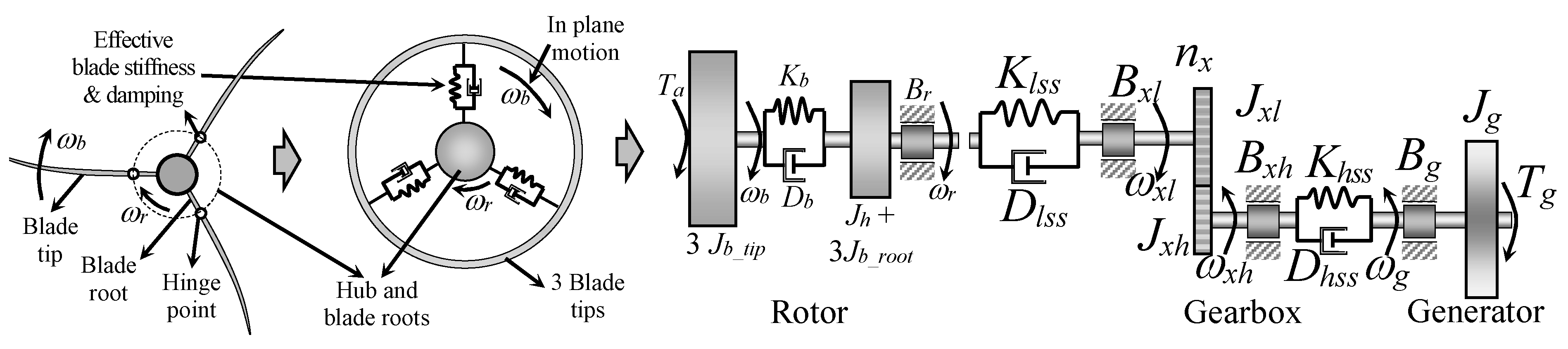
Figure 5.
Block diagram of the observer with the PI controller for the unknown input.
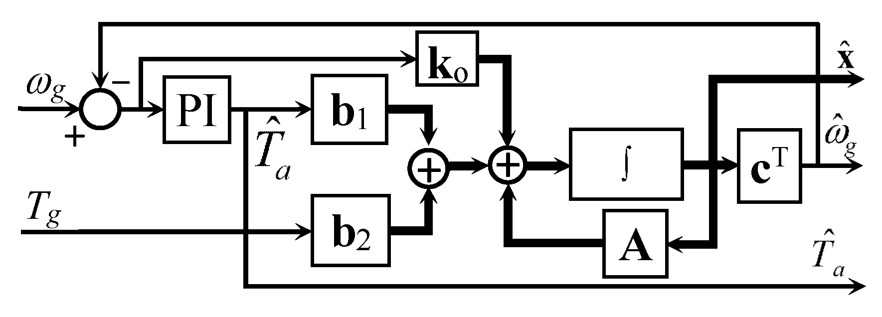
Figure 6.
Interval observer with effective wind speed estimation.

Figure 7.
Sensibility functions for (a) power, (b) aerodynamic torque, and (c) thrust force.

Figure 8.
Estimation results for (a) effective wind speed and (b) collective tip deflection [74].
Figure 8.
Estimation results for (a) effective wind speed and (b) collective tip deflection [74].
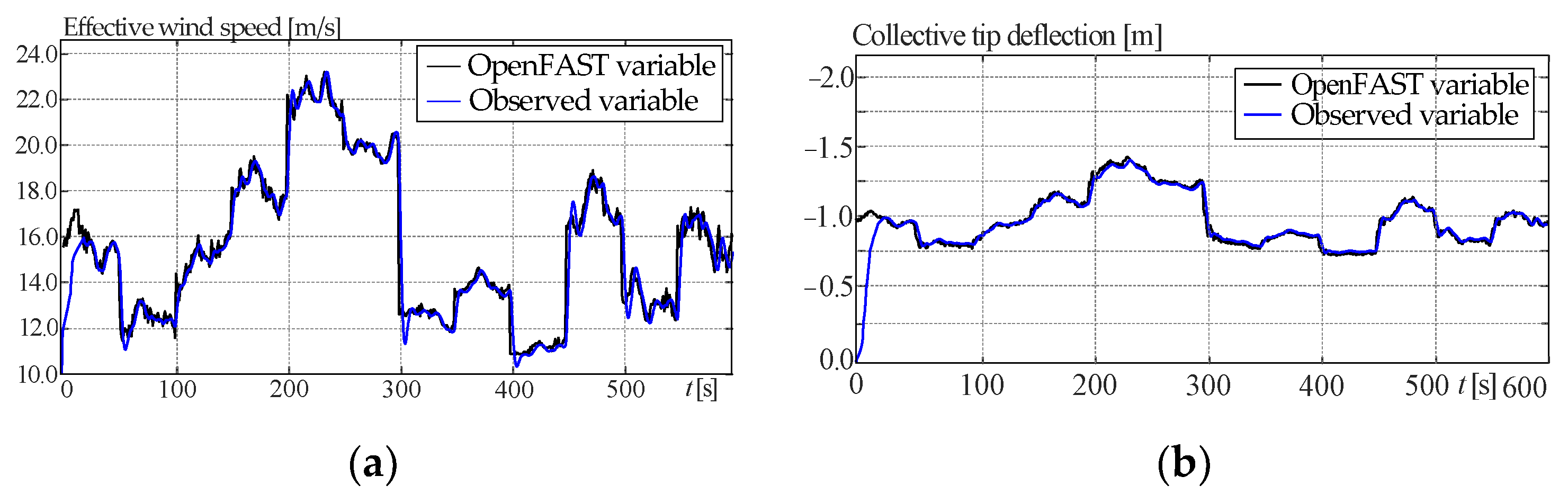
Figure 9.
Blade tip deflections with and without ABDC.

Figure 10.
Power conversion with and without ABDC.
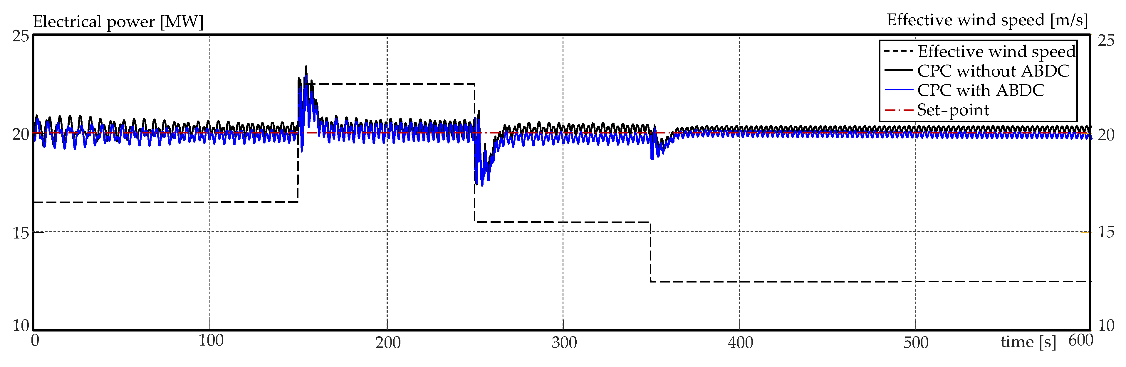
Figure 11.
Pitch activity for both control systems.

Table 1.
Rated values of the 20 MW wind turbine for the rated wind speed.
| Variables | Notation | Rated Values | Units |
|---|---|---|---|
| Rated mechanical power | Pm,rated | 21.191 | MW |
| Rated rotor speed | ωr,rated | 7.1567 | rpm |
| Rated generator speed | ωg,rated | 1173.7 | rad/s |
| Cut-in, rated, and cut-out wind speed | vci, vw,rated, vco | 4.48, 10.92, 25 | m/s |
| Rated aerodynamic torque (on the low-speed shaft) | Ta,rated | 28,434.7 | kNm |
| Rated generator torque (on the high-speed shaft) | Tg,rated | 169.76 | kNm |
| Maximum value of the power coefficient Cp | Cp,max | 0.4812 | -- |
| Optimal tip-speed ratio | λ* | 10.115 | -- |
| Density of air | ρa | 1.225 | kg/m3 |
Table 2.
Main design parameters of the 20 MW wind turbine.
| Parameters | Notation | Values | Units |
|---|---|---|---|
| Rotor mass moment of inertia | Jr | 2919.66 × 106 | kg m2 |
| Generator mass moment of inertia | Jg | 7248.32 | kg m2 |
| Hub mass moment of inertia | Jh | 2.1 × 10⁶ | kg m2 |
| Blade mass moment of inertia | Jb | 972.52 × 10⁶ | kg m2 |
| Rotor radius | R | 138 | m |
| Equivalent shaft spring constant | Kr | 6.94 × 10⁹ | Nm/rad |
| Equivalent shaft damping constant | Dr | 4.97 × 10⁷ | Nm/(rad/s) |
| Generator friction coefficients | Bg | 0.02 | |
| Damping constant of the low-speed shaft | Dlss | 1.99 × 10³ | Nm/(rad/s) |
| Damping constant of the high-speed shaft | Dhss | 7.09 × 10⁸ | Nm/(rad/s) |
| Stiffness constant of the low-speed shaft | Klss | ||
| Stiffness constant of the high-speed shaft | Khss | ||
| Gearbox efficiency, generator efficiency | ηx, ηg | 97.8, 96.1 | % |
| Gearbox ratio | nx | 164 | --- |
| First-in-plane blade frequency | 0.6277 | Hz | |
| Structural damping ratio | 0.48 | % | |
| Blade cone angle | 4 | deg |
Table 3.
Interval parameters.
| Variables | Notation | Inferior Limit | Superior Limit | Units |
|---|---|---|---|---|
| Moment of inertia of all three blades | Jbe | 7.1149 × 10⁵ | 1.2299 × 10⁹ | kg m2 |
| Blade moment of inertia of three rates | J3roots | 2.9168 × 10⁹ | 2.9176 × 10⁹ | kg m2 |
| Damping coefficients of the low-speed shaft | Dlss | |||
| Damping coefficients of the high-speed shaft | Dhss | |||
| Damping coefficient of the blades | Db | 1.5831 × 10⁵ | 2.1216 × 10⁸ | Nm/(rad/s) |
| Stiffness coefficient of the blades | Kb | 3.5227 ×10⁶ | 3.6599 × 10⁹ | Nm/rad |
Table 4.
Goodness of estimated variables (from [74]).
Table 4.
Goodness of estimated variables (from [74]).
| Variables | Cross-Correlation | RMSE |
|---|---|---|
| Generator speed | 0.9973 | 0.2671 |
| Aerodynamic torque | 0.9967 | 0.6823 |
| Effective wind speed | 0.9990 | 0.7049 |
| Collective tip deflection | 0.9998 | 0.0234 |
Table 5.
Controller parameters.
| Parameter | CPC Only | CPC + ABDC |
|---|---|---|
| Kp of CPC | 1.4970 | 0.0201 |
| Ki of CPC | 3.3980 | 0.0134 |
| Kbc of ABDC | ---- | 5.6320 |
| Dbc of ABDC | ---- | 2808.3 |
Disclaimer/Publisher’s Note: The statements, opinions and data contained in all publications are solely those of the individual author(s) and contributor(s) and not of MDPI and/or the editor(s). MDPI and/or the editor(s) disclaim responsibility for any injury to people or property resulting from any ideas, methods, instructions or products referred to in the content. |
© 2024 by the authors. Licensee MDPI, Basel, Switzerland. This article is an open access article distributed under the terms and conditions of the Creative Commons Attribution (CC BY) license (https://creativecommons.org/licenses/by/4.0/).
Share and Cite
MDPI and ACS Style
Chamoli, S.; Gambier, A. Active Edgewise Blade Damping Control of Large Wind Turbines by Using the Pitch Controller and an Interval Observer. Actuators 2024, 13, 58. https://doi.org/10.3390/act13020058
AMA Style
Chamoli S, Gambier A. Active Edgewise Blade Damping Control of Large Wind Turbines by Using the Pitch Controller and an Interval Observer. Actuators. 2024; 13(2):58. https://doi.org/10.3390/act13020058
Chicago/Turabian StyleChamoli, Suryans, and Adrian Gambier. 2024. "Active Edgewise Blade Damping Control of Large Wind Turbines by Using the Pitch Controller and an Interval Observer" Actuators 13, no. 2: 58. https://doi.org/10.3390/act13020058
Note that from the first issue of 2016, this journal uses article numbers instead of page numbers. See further details here.