3.1. Simulation Result
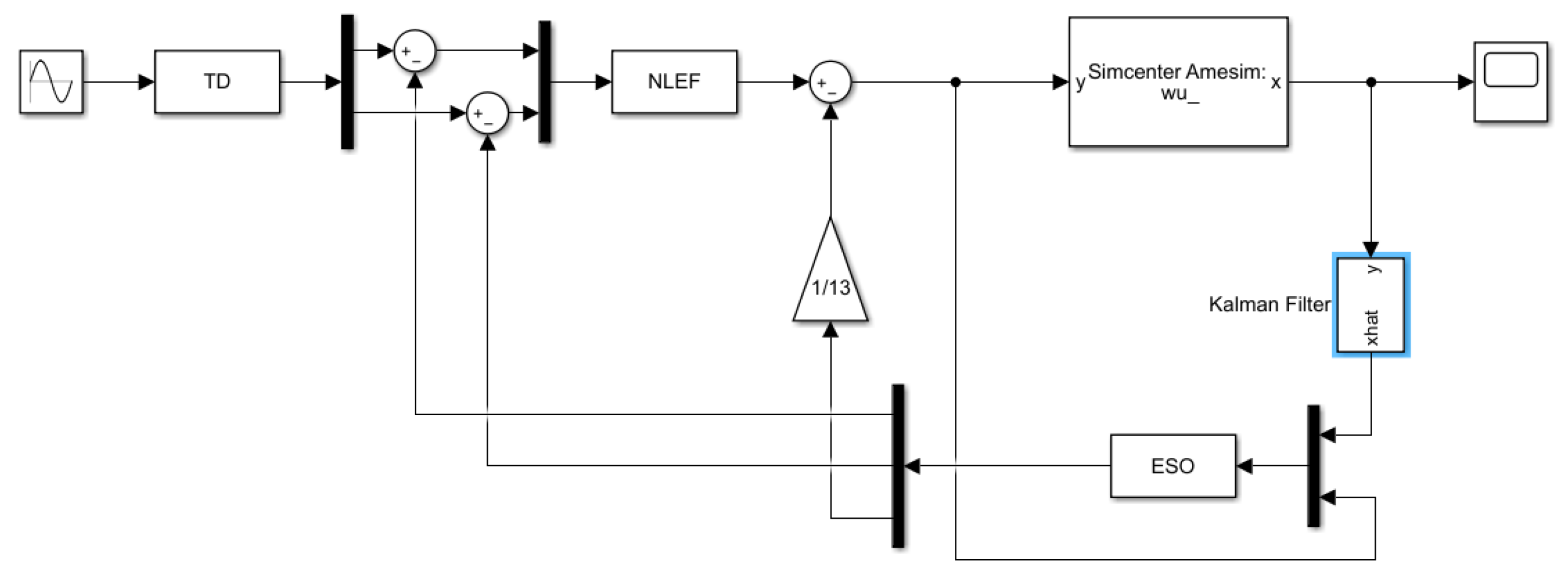
This study utilizes Amesim and Simulink for combined simulation to validate the feasibility of the algorithm. The physical model designed in Amesim is depicted in
Figure 3, while the mathematical model of the algorithm designed in Simulink is presented in
Figure 4.
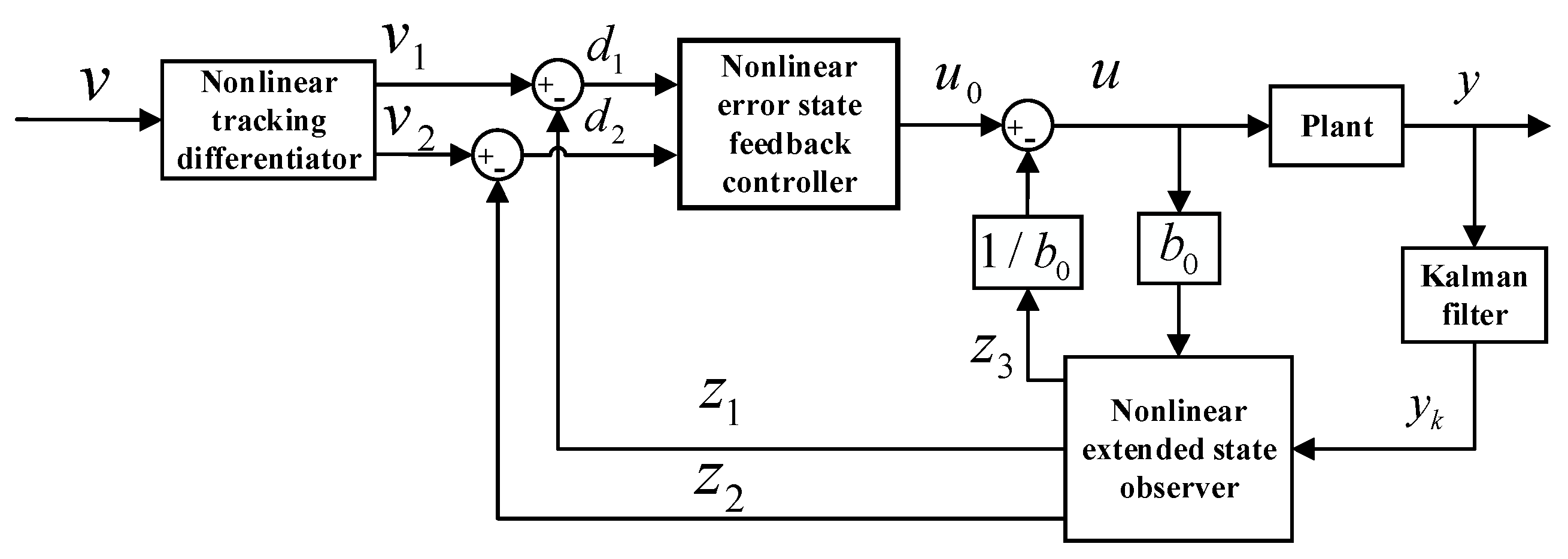
The specific working principles are explained using the active disturbance-rejection controller with integrated Kalman filter (ADRCKF) as an example. The angle sensor in
Figure 3 captures the actual output angle and the expected angle signal and calculates the difference to obtain the error, which is then input into the PID controller to obtain the control quantity. The control quantity is multiplied by a gain to generate a control voltage that is input to the valve. The control voltage regulates the opening area of the valve interface, controlling gas flow. Changes in flow impact the position output, achieving closed-loop control of the position. This constitutes the position-disturbance control part on the position side. The position disturbance is applied to the torque control part, introducing an additional position disturbance. The primary objective of this paper is to achieve precise torque control under external position disturbance. The control principle on the torque side is as follows: The torque sensor in
Figure 3 captures the actual torque output signal, which is then transmitted to the Interface block. The Interface block, through the control Simulink algorithm in
Figure 4, generates a control quantity that is transferred to the valve. By controlling the voltage of the valve, the opening area of the valve is regulated, achieving flow control. Changes in flow influence the torque output, realizing closed-loop control of torque. The algorithm principles in
Figure 4 were already explained when introducing
Figure 2 and will not be reiterated here.
Due to the interference of the position system with the torque system, oscillations occur in the torque system, particularly at the reversal point, as illustrated in the simulation results in
Figure 5a,c. The research challenge addressed in this study revolves around mitigating the adverse effects caused by the interference of the position system with the torque system, with the aim of achieving precise torque control.
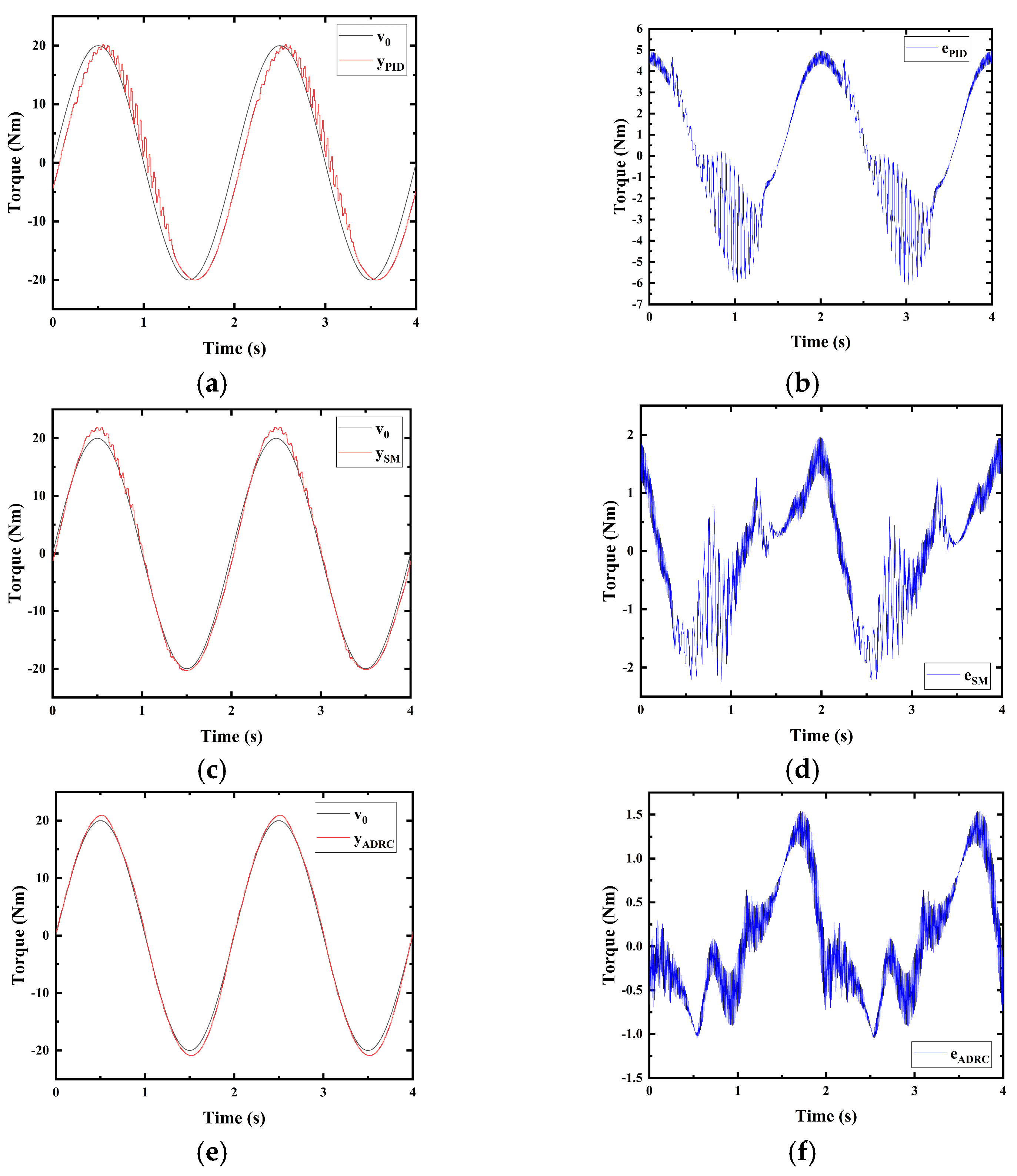
The paper presents a simulation comparison of a PID, an SM, an ADRC, and an ADRCKF controller with an amplitude of 20 Nm and a frequency of 0.5 Hz, as depicted in
Figure 5.
Figure 5a depicts the simulation results of PID torque trajectory tracking, which shows evident oscillations. The PID controller lacks disturbance-rejection capability, leading to significant oscillations at the reversal point of the torque signal due to interference from the position system.
Figure 5b represents the torque trajectory-tracking error for PID, with a maximum error of 6 Nm.
Figure 5c illustrates the simulation results of SM torque trajectory tracking, displaying slight oscillations. The disturbance-rejection capability of the sliding-mode controller is slightly superior to that of PID, consequently leading to a reduced magnitude of oscillations compared with PID.
Figure 5d shows the torque trajectory-tracking error for SM, with a maximum error of 2.3 Nm.
Figure 5e displays the simulation results of ADRC torque trajectory tracking, without oscillations. Owing to the strong disturbance-rejection capability and robustness of the active disturbance-rejection controller, oscillations are virtually eliminated.
Figure 5f presents the torque trajectory tracking error for the ADRC, with a maximum error of 1.6 Nm.
Figure 5g shows the simulation results of the ADRCKF torque trajectory tracking. The ADRCKF exhibits superior disturbance-rejection capability and robustness; oscillations are completely eliminated, and the output signal closely adheres to the desired signal.
Figure 5h represents the torque trajectory-tracking error for the ADRCKF, with a maximum error of 1.1 Nm. Note that 1.1 Nm < 1.6 Nm < 2.3 Nm < 6 Nm. The simulation results validate the effectiveness and superiority of the ADRCFK control strategy.
The maximum errors of PID, SM, ADRC, and ADRCKF controllers in simulating sinusoidal-torque trajectory tracking with an amplitude of 20 Nm and a frequency of 0.5 Hz are presented in
Table 2.
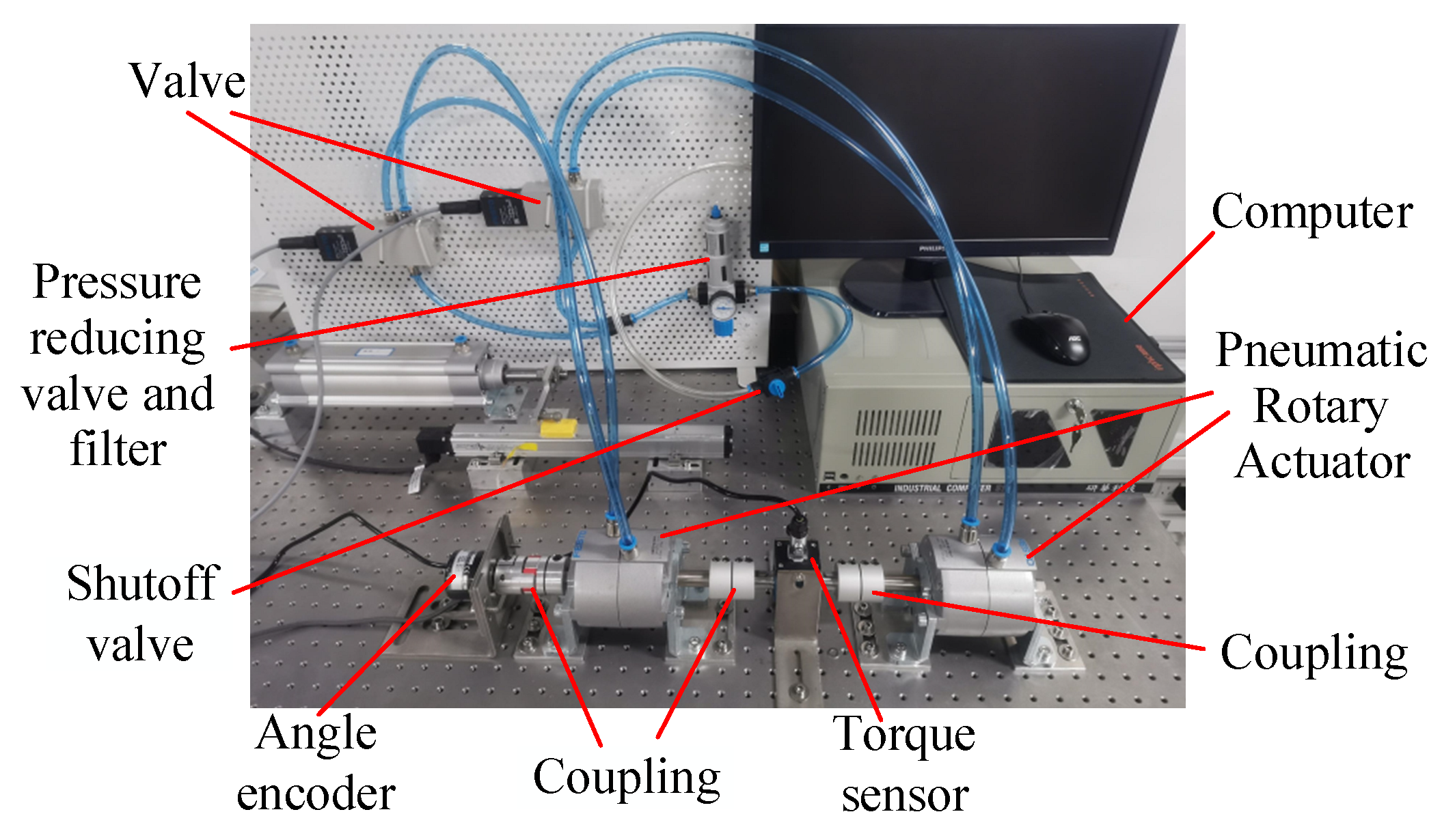
3.2. Experimental Results
The experimental setup examined in this research is a pneumatic-torque system that is based on position disturbance, and it is illustrated in
Figure 6.
Using an experimental air-pressure condition of 0.7 MPa, an experiment was conducted to measure the dead zone of the proportional valve, which was found to be between 4.9 V and 5.1 V. The following parameters were used to design the ADRCKF:
For different experiments, the parameters were set differently. For the sinusoidal-torque trajectory tracking at a frequency of 0.5 Hz, , and . For the 1 Hz sinusoidal-torque trajectory tracking, , and .
In the presence of position disturbance with a frequency of 0.5 Hz and an amplitude of 85°, the PID controller conducted a sinusoidal-torque trajectory tracking experiment with a frequency of 0.5 Hz and an amplitude of 20 Nm, as illustrated in
Figure 7. The active disturbance-rejection controller (ADRC), the active disturbance-rejection controller integrated with a Kalman filter (ADRCKF), and the sliding-mode controller (SM) performed a sinusoidal-torque trajectory-tracking experiment with a frequency of 0.5 Hz and an amplitude of 20 Nm, as shown in
Figure 8. Under the conditions of position disturbance with a frequency of 1 Hz and an amplitude of 85°, the ADRC, ADRCKF, and SM conducted sinusoidal-torque tracking experiments with a frequency of 1 Hz and an amplitude of 20 Nm, as presented in
Figure 9.
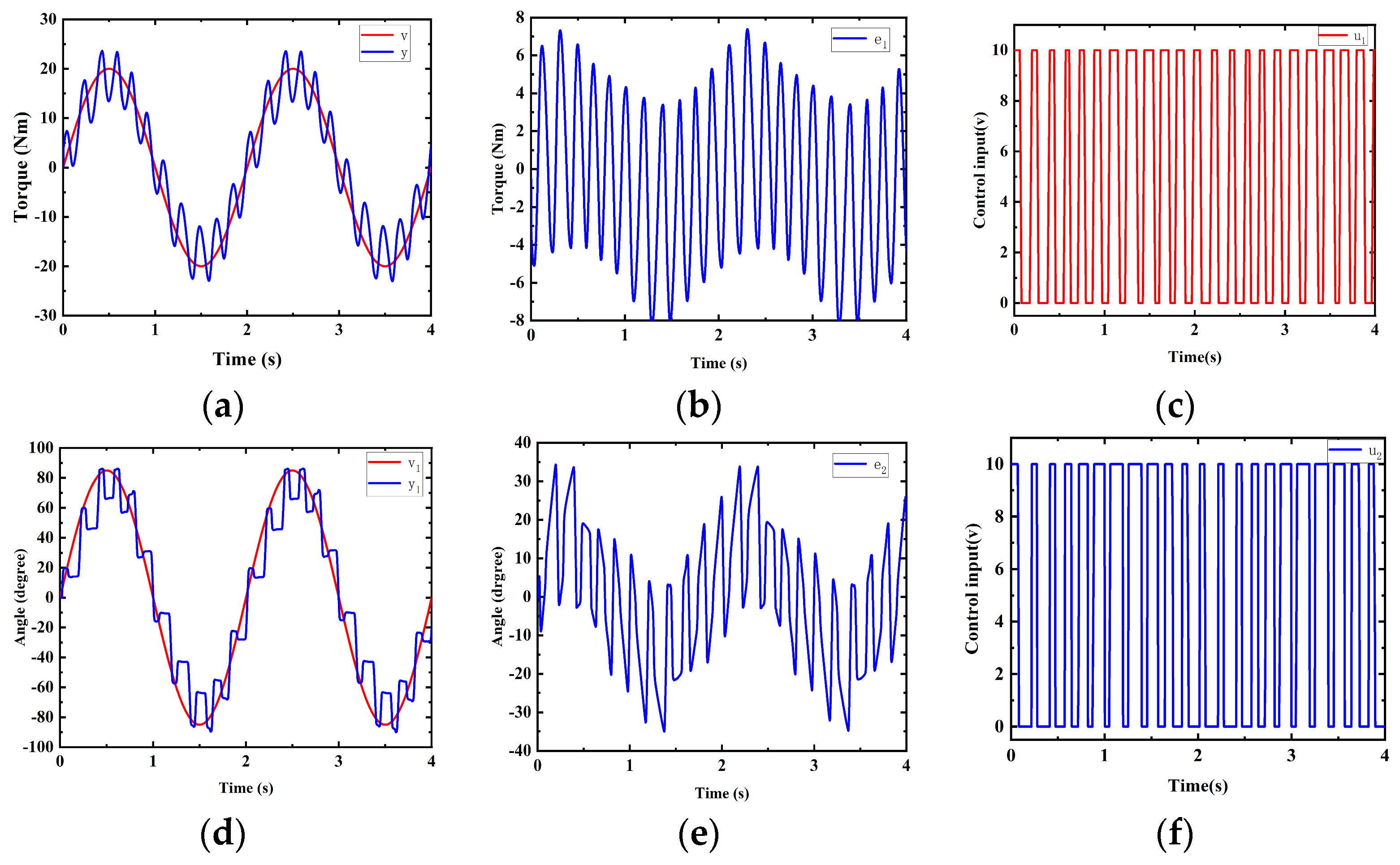
Figure 7 illustrates experiments of a pneumatic-torque servo control controlled by a PID controller that is based on position disturbance. The position disturbance signal is a sinusoidal signal with an amplitude of 85° and a frequency of 0.5 Hz. The torque signal to be controlled is a sinusoidal signal with an amplitude of 20 Nm and a frequency of 0.5 Hz.
Figure 7a,d, respectively, show the output
of torque trajectory tracking and the angle output
of the position-disturbance part.
Figure 7b,e show the corresponding tracking errors
and
, which are 8 Nm and 35 degrees, respectively.
Figure 7a,d exhibit significant oscillations. This is attributed to the poor robustness of the PID controller and the series connection of the position output terminal and the torque output terminal, leading to mutual interference.
Figure 7c,f display the control voltage
and
of the valve in the torque and position systems, respectively. It can be observed that the voltage of both valves reached the limit, indicating that the valves are operating at their optimal performance. This results in the system control accuracy being at its highest level.
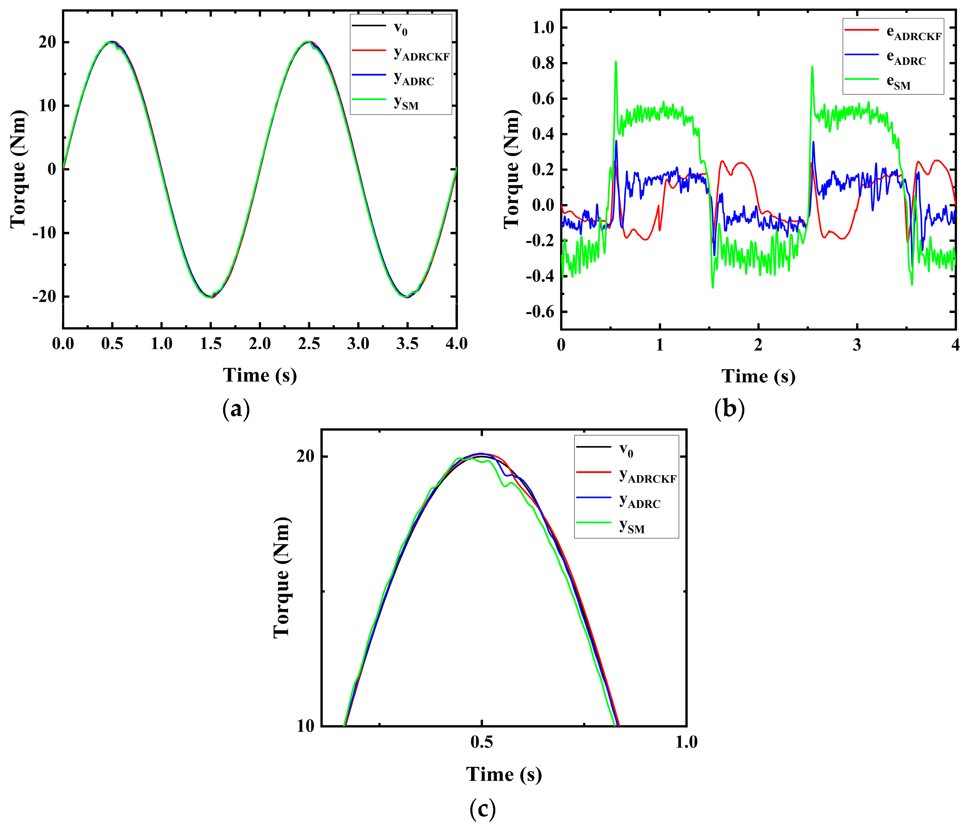
Figure 8 depicts the experiments of sinusoidal-torque trajectory tracking based on position disturbances. The controlled torque signal is a sinusoidal signal with an amplitude of 20 Nm and a frequency of 0.5 Hz, while the position disturbance signal is a sinusoidal signal with an amplitude of 85° and a frequency of 0.5 Hz.
Figure 8a illustrates the sinusoidal-torque trajectory-tracking experiment controlled by an ADRCKF, an ADRC, and an SM, where the output signals
,
, and
rapidly track the desired torque signal
.
Figure 8b represents the tracking errors in the sinusoidal-torque trajectory controlled by the ADRC, ADRCKF, and SM, with maximum tracking errors of 0.25 Nm, 0.38 Nm, and 0.8 Nm for
,
, and
, respectively. Note that 0.25 Nm < 0.38 Nm < 0.8 Nm < 8 Nm.
Figure 8c shows a comparatively enlarged view of the ADRCKF, ADRC, and SM under position disturbances during the sinusoidal-torque trajectory-tracking experiment. At the commutation point, the outputs
,
, and
of the three controllers both oscillated, but the ADRCKF was less affected by oscillations, resulting in higher control accuracy. This indicates that the Kalman filter effectively enhances system robustness and suppresses system oscillations.
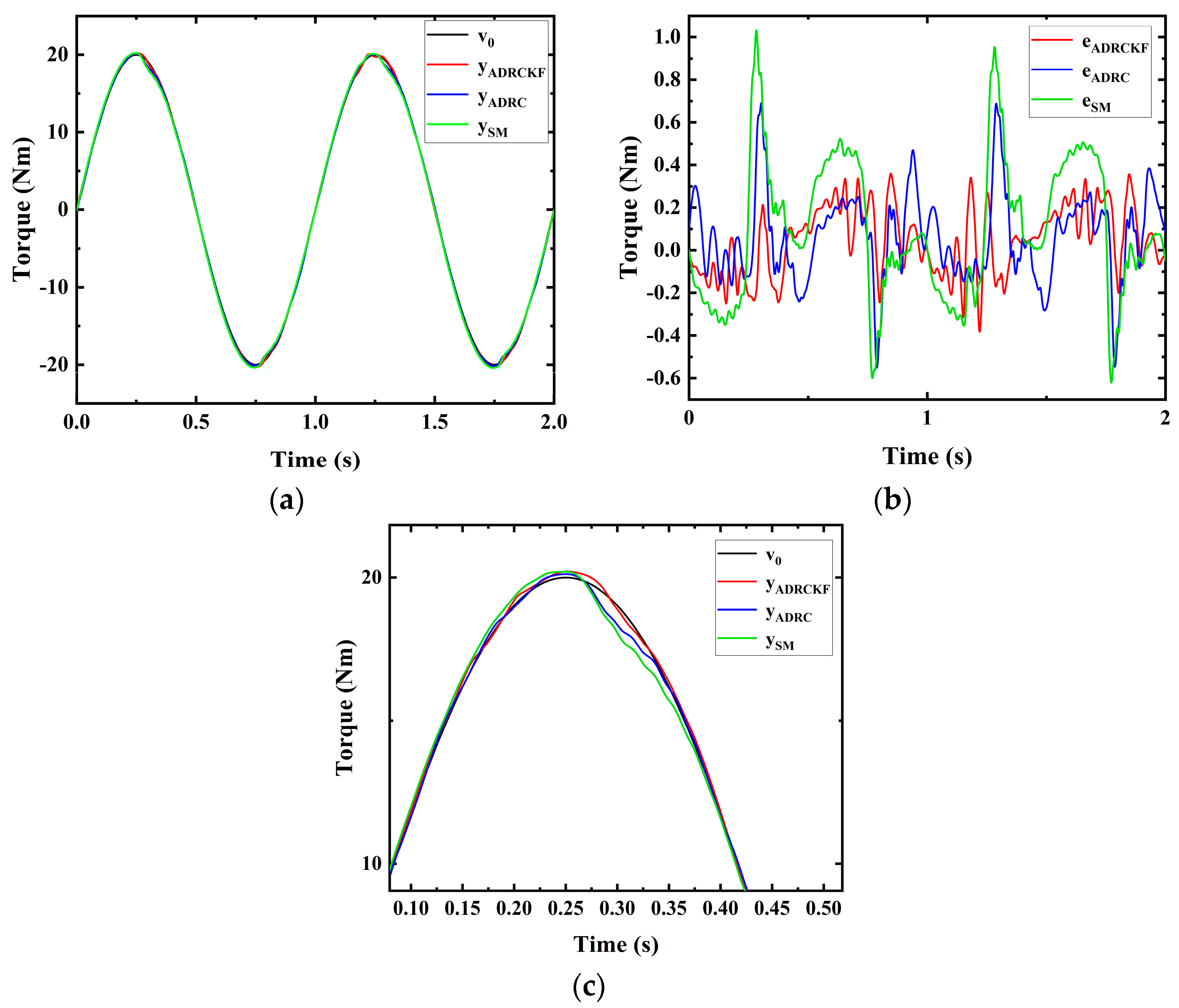
Figure 9 depicts experiments of a pneumatic-torque servo control based on position disturbance, controlled by an ADRCKF, an ADRC, and an SM. The controlled torque signal is a sinusoidal signal with an amplitude of 20 Nm and a frequency of 1 Hz, while the position disturbance signal is a sinusoidal signal with an amplitude of 85° and a frequency of 1 Hz. In
Figure 9a, the sinusoidal-torque tracking experiment controlled by an ADRCKF, an ADRC, and an SM is depicted, with the output signals
,
, and
rapidly tracking the desired torque signals. In
Figure 9b, the sinusoidal-torque trajectory-tracking errors controlled by the ADRCKF, ADRC, and SM are shown, with maximum tracking errors of 0.4 Nm, 0.7 Nm, and 1.0 Nm for
,
, and
, respectively. Note that 0.4 Nm < 0.7 Nm < 1.0 Nm. The experiment once again demonstrates the superior performance of the ADRCKF.
This paper, under the condition of position disturbance with a frequency of 0.5 Hz and an amplitude of 85°, designed three sets of experiments for tracking sinusoidal-torque trajectories with a frequency of 0.5 Hz and an amplitude of 20 Nm for comparison. The four controllers used were the PID, ADRCKF, ADRC, and SM. The tracking errors for the four sets of experiments are shown in
Figure 7b and
Figure 8b, which are 8 Nm, 0.25 Nm, 0.36 Nm, and 0.8 Nm, respectively. Additionally, it explored the tracking of a sinusoidal torque with a frequency of 1 Hz and an amplitude of 20 Nm using an ADRCKF, an ADRC and an SM under the condition of position disturbance with a frequency of 1 Hz and an amplitude of 85°, as illustrated in
Figure 9a. The tracking errors are 0.4 Nm, 0.7 Nm, and 1.0 Nm respectively, as shown in
Figure 9b.
The maximum errors in the results of the 0.5 Hz sinusoidal-torque tracking experiments under different control strategies are shown in
Table 3, while the maximum errors in the results of the 1 Hz sinusoidal-torque tracking experiments under different control strategies are presented in
Table 4.
In addition to utilizing the maximum-error metric, the integral absolute-error metric (IAE) is also employed. Over a specified time period, the absolute values of errors for various controllers are integrated to derive the IAE metrics. The IAE metrics for the 0.5 Hz sine experiment are presented in
Table 5, while the IAE metrics for the 1 Hz sine experiment are detailed in
Table 6.
Remark 2. Sinusoidal-torque trajectory tracking based on position disturbance shows the poor performance of the PID controller. This is because the position output and torque output interfere with each other, and the PID controller lacks robustness, making the torque-control part unable to resist interference from the position side. In contrast, the SM, the ADRC, and the ADRCKF controllers demonstrate strong robustness and high disturbance-rejection capabilities, leading to more satisfactory torque trajectory-tracking control. However, integrating the Kalman filter into the ADRC controller improves the purity of the feedback signal, increases the robustness of the controller, reduces oscillations, and enhances control precision.


