Abstract
Traditional industrial robots often face challenges in achieving a perfectly polished surface on a workpiece because of their high mechanical rigidity. The active compliance force control device installed at the robotic arm’s end enables high-precision contact force control between the grinding tool and the workpiece. However, the complex hysteresis nonlinearity between cylinder air pressure and output force, as well as various random disturbances during the grinding process, can affect the accuracy of the contact force and potentially impact the grinding effect of the workpiece, even causing irreversible damage to the surface of the workpiece. Given the complex random variation of cylinder output force in the actual grinding process, a rate-dependent hysteresis model based on diagonal recurrent neural network and Pradtl–Ishlinskii models named dRNN-PI is designed to compensate for the complex nonlinear hysteresis of the cylinder and calculate the desired air pressure to maintain a steady contact force on the workpiece. The proxy-based sliding mode control (PSMC) is utilized to quickly track the desired air pressure without overshooting. This paper also proves the controller’s stability using the Lyapunov-based methods. Finally, the accuracy of the proposed hysteresis compensation model and the effectiveness and robustness of the PSMC are verified by experiment results.
1. Introduction
Robot grinding, as a material removal process, is widely used in industrial fields such as aviation [1], automobiles, and ships, and is widely applied in the processes of surface polishing [2,3,4,5], deburring [6,7,8,9], weld grinding [10,11], etc. Satio and Miyoshi discovered [12] that the control accuracy and stability of the contact force between the grinding tool and the workpiece during the grinding process determine the machining accuracy and surface roughness of the workpiece. Most existing robotic arms adopt position control methods and have high mechanical stiffness [13]. When there is a small displacement deviation between the end of the robotic arm and the workpiece, or there are small protrusions or burrs on the surface of the workpiece, it may cause a strong impact between the grinding tool and the workpiece. In addition, the robotic arm directly participates in the grinding process through position control, which has bottleneck problems such as inaccurate measurement, imprecise control, and slow response. This seriously restricts the application of robotic arms in high-precision grinding processing. Therefore, it is difficult for traditional position control to meet the needs of high-precision grinding of robotic arms. Introducing a compliance control method is necessary to resist the impact during the grinding process.
Compliance control can be divided into two categories: passive compliance control and active compliance control [14]. Passive compliance refers to the natural interaction between mechanical devices and the external environment through mechanical structures when they come into contact [15]. Passive compliance has a simple structure, no special requirements for the robotic arm, and decentralized force and position control, making it easy to achieve. Nevertheless, its force control accuracy is relatively low. Active compliance control uses a force sensor of six dimensions installed on the tool link end of the industrial robots to provide real-time feedback on the current output force [16,17,18,19], and adopts a specific control strategy to control the force actively. The current mainstream active compliance control methods can be divided into impedance control, admittance control, and force position hybrid control. Active compliance control generally has high control accuracy, but shortcomings such as slow response speed, high debugging difficulty, and few suitable grinding process scenarios exist. If the strong points of passive compliance control and active compliance control can be combined, a high-precision and highly adaptive grinding control method can be achieved [13,20,21]. In [21], the author utilizes a gas dynamics model and a pneumatic spring model to establish a model between the output force of the cylinder and the feedback voltage of the pressure-regulating valve and uses a fuzzy PID controller for control. Simulation results show that this method has a faster response speed and smaller overshoot compared to PID control methods. However, the established model between cylinder output force and air pressure cannot effectively compensate for the cylinder’s hysteresis characteristics, resulting in a lagging tracking performance. In [13], the author approximates the hysteresis loop of the cylinder as two straight lines and utilizes a robust controller for tracking control. The proposed method compensates for cylinder hysteresis and reduces hysteresis characteristics. The robust controller is simple and can easily prove the stability of the controller. However, the proposed hysteresis model that approximates two segments cannot fit well with rate-dependent hysteresis characteristics in actual grinding processes. At the same time, the controller also has the problem of overshooting, which may cause irreversible damage to the surface of the workpiece during the actual grinding process.
Considering the problems of the existing methods mentioned above and based on the idea of combining active and passive compliance, this paper designs a high-precision compliant polishing system driven by a cylinder that can be integrated into the end of an existing robotic arm [22,23]. A cylinder mainly drives the system and uses a high-precision proportional pressure-regulating valve to detect the air pressure inside the cylinder, achieving high-precision contact force control.
As a driving element, the cylinder has advantages such as fast response speed and specific passive compliance characteristics. However, as a pneumatic component, the cylinder has complex nonlinear hysteresis problems that need to be compensated during the design of the control system [24]. This article adopts the method of constructing a system hysteresis inverse model for feedforward compensation, thus constructing an open-loop control system. The control accuracy of a feedforward control system is decided by the performance of the inverse hysteresis model [25]. The traditional mathematical form of hysteresis models includes the Prandtl–Ishlinskii model (PIm), Preisach model, Bouc Wen model, Maxwell Slip model, Duhem model, etc. [25]. Furthermore, Vaiana and Rosati [26,27] classified hysteresis loops into four categories according to the analytical properties of their limiting curves and proposed a unified modeling approach. Although these models mentioned above have good hysteresis fitting effects for low-frequency or constant-frequency inputs, the fitting effect is poor when there are dynamic characteristics (changes in input frequency) and irregular effects in the hysteresis system. In the actual grinding process, there may be some dynamic changes in the expected contact force. To better satisfy the requirements of high-precision grinding under such conditions, it is necessary to design a hysteresis model with high fitting accuracy under frequency changes [28]. This paper proposes a rate-dependent hysteresis model that combines the diagonal recurrent neural network and the Prandtl–Ishlinskii model (PIm), named dRNN-PIm, to address the problems of traditional mathematical hysteresis models. The proposed hysteresis model’s direct inverse is used to plan cylinder input pressure based on its expected output force.
After planning the expected cylinder input air pressure, the compliant grinding system controls the input air pressure in the cylinder through a proportional pressure-regulating valve [28]. The proportional pressure-regulating valve can be approximately modeled as a second-order linear system, with the input of the proportional valve being an analog voltage signal and the output being the cylinder air pressure. The proxy-based sliding mode control (PSMC) method is applied for the first time in controlling the proportional pressure-regulating valve cylinder system. This method was originally proposed by R. Kikuuwe and S. Yasukouchi [29].
Based on the aforementioned discussions, this article’s primary contribution can be summarized as follows:
- 1.
- This article proposes a rate-dependent hysteresis model that uses a diagonal recurrent neural network and Prandtl–Ishlinskii model (dRNN-PIm) to solve problems related to the rate of air pressure and output force of the cylinder.
- 2.
- The proxy-based mode control (PSMC) method is applied for the first time in controlling the proportional pressure-regulating valve cylinder system. The control method has a fast control response characteristic and can effectively prevent overshoot during the grinding control process, thereby avoiding irreversible damage to the surface of the workpiece, such as scratches and dents.
- 3.
- This article considers the large number of irregular burrs on the workpiece surface that are difficult to model as non-matching disturbances in the system. The stability of the controller is derived and proven, and the anti-interference performance of the controller is verified through experiments to quickly recover and track the desired air pressure under irregular, non-matching disturbances.
The research content of the paper includes the following: Section 2 is the problem statement, Section 3 provides a rate-dependent hysteresis model that combines diagonal recurrent neural network and Prandtl–Ishlinskii models, Section 4 provides an adaptive sliding mode control method based on virtual objects and the proof of the control method’s stability, Section 5 is the experimental results, and Section 6 is a summary of the entire text.
2. Problem Statement
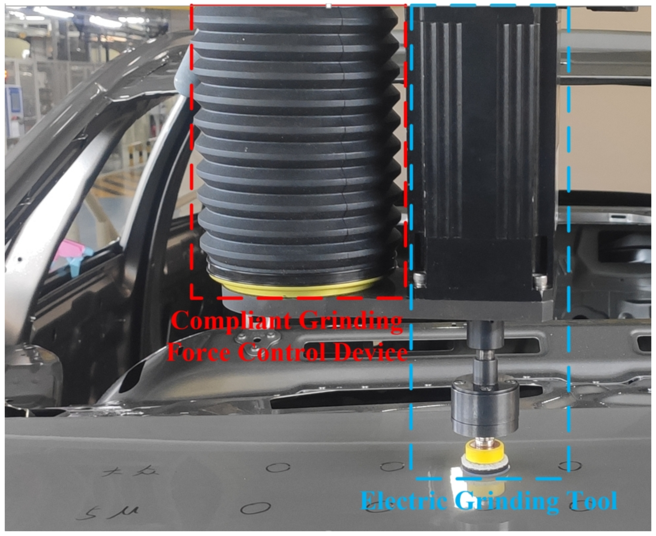
This section will introduce the compliant grinding device’s working principle and main control objects. The practical application scenario of compliant grinding is shown in Figure 1. Figure 2 shows the compliant grinding device’s physical diagram. The compliant grinding device consists of a proportional pressure-regulating valve, an electromagnetic directional valve, a low-friction cylinder, a single-axis angle sensor, and a magnetic induction displacement sensor. The proportional pressure-regulating valve has the functions of both air pressure regulation and air pressure measurement. Therefore, by connecting the pressure-regulating valve to the front of the cylinder, the current air pressure value of the cylinder can be detected in real time. This article models the load end, cylinder, and proportional pressure-regulating valve separately, unlike the traditional overall control system modelling method.
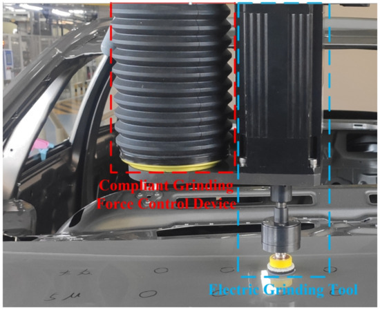
Figure 1.
Application of compliant grinding device in automotive paint surface precision processing.
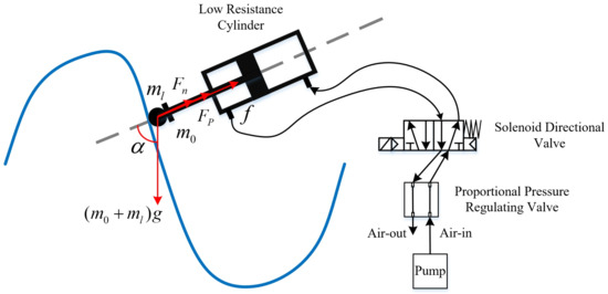
Figure 2.
Force analysis and pneumatic circuit schematic diagram of the load end of the compliant grinding device.
The schematic diagram illustrating the input and output of the compliant grinding device is presented in Figure 2. The modelling for the load end can be carried out according to the following expression:
In the above equation, and represent the masses of the compliant device’s movable end and the load tool at the movable end, respectively. Both and are obtained by weighing. is the angle between the compliance device’s axial and gravity directions obtained through the single-axis angle sensor. f is the combined force of cylinder piston friction and guide rail friction, identified through experimental data collection. G represents the acceleration of gravity. The symbol represents the force of contact between the grinding tool and the surface of the workpiece. is the output force of the cylinder, which is influenced by factors such as the size of air pressure and the rate of change in air pressure, and exhibits certain hysteresis characteristics. Section 3 will elaborate on this in detail.
This article approximates the proportional pressure-regulating valve as a second-order linear system, as shown in the transfer function below:
The coefficients and c are identified from the step input voltage and corresponding feedback pressure collected through experiments. The transfer function can then be rewritten as follows:
In the above equation, p is the feedback air pressure of the proportional pressure-regulating valve, u is the input analog control voltage, and is the disturbance signal.
The control framework for the compliant device in this article consists of two parts: planning and control. The planning part calculates the required cylinder output force corresponding to the target contact force through (1), and then calculates the required air pressure p in the cylinder through the constructed inverse model of cylinder hysteresis fitting. The control part is for the controller to quickly track and respond to the cylinder pressure p.
3. Calculation of Expected Air Pressure
The output force of the cylinder is not strictly proportional to the air pressure due to the presence of a hysteresis loop. To achieve an accurate management of the resultant force, it is necessary to compensate for the hysteresis of the cylinder. This section proposes a rate-dependent hysteresis model based on dRNN and PIm models, which can have a more accurate fitting effect on the hysteresis loop of variable frequency input air pressure.
3.1. Rate-Dependent Hysteresis Characteristics of Cylinders
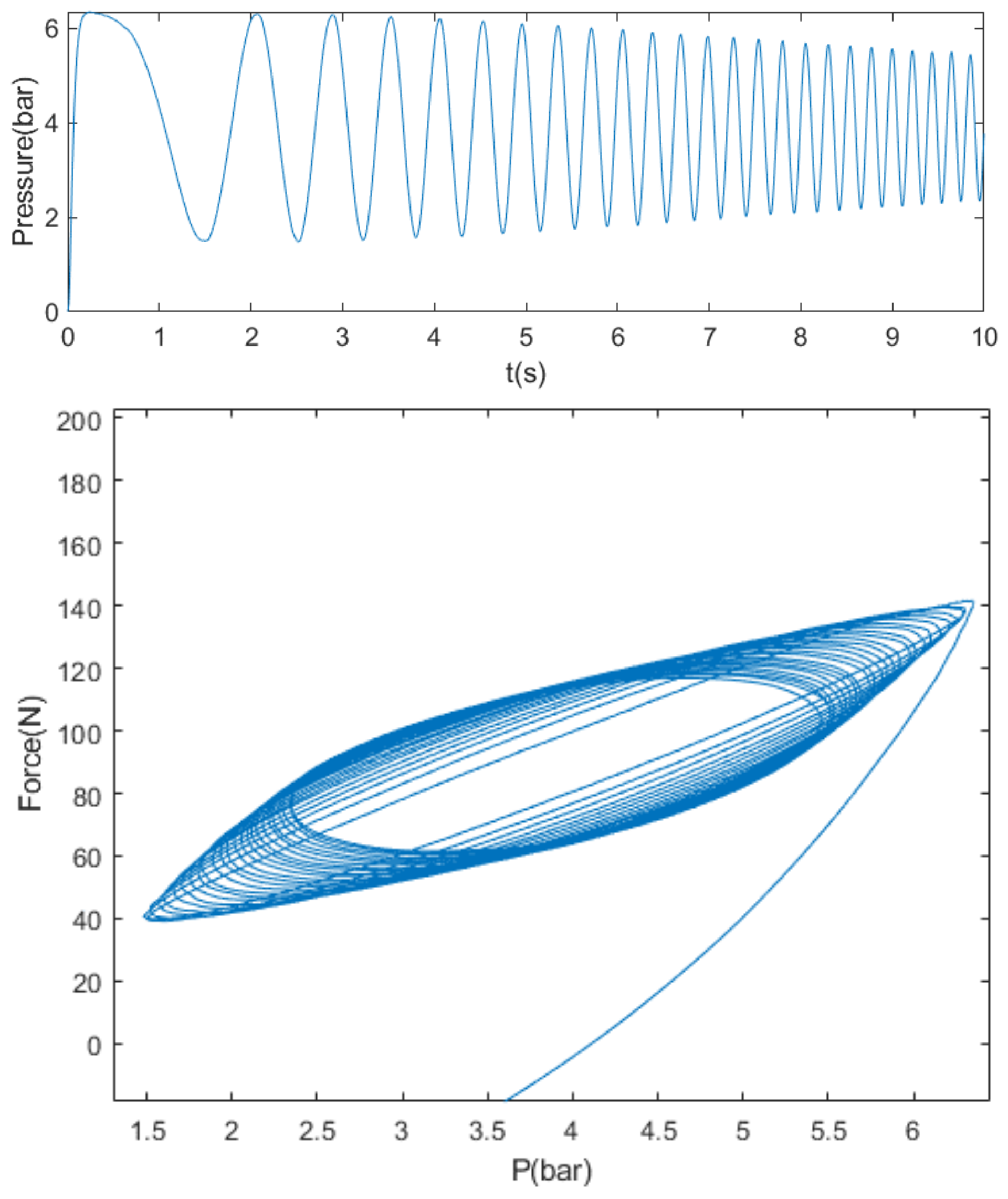
The hysteresis loop of the cylinder is obtained from experimental tests of inputting continuously varying air pressure with a frequency range of 0–5 Hz into the cylinder of the compliance device, as depicted in Figure 3.

Figure 3.
The hysteresis loop obtained by the experimental tests between the input pressure and the output force of the cylinder.
It can be observed from Figure 3 that the hysteresis loop’s shape alters with the input air pressure’s frequency. The loop’s width gradually increases as the frequency increases. In addition, it can be seen that the curve of the rising section of the air pressure does not coincide with the curve of the falling section. From this, it can be seen that the hysteresis characteristics of the cylinder have a significant impact on the accuracy of the open-loop control system of the compliance device. Therefore, it is necessary to fit and compensate for the hysteresis of the cylinder.
3.2. A Rate-Dependent Hysteresis Model Based on dRNN and PIm Players
This article improves the traditional Prandtl–Ishlinskii model (PIm) and introduces a diagonal recurrent neural network (dRNN).
The conventional PIm hysteresis model is achieved through the addition of several backlash operators that are weighted and summed up:
In Equation (4), the PIm model contains n backlash operators, where it is the input variable of the PIm hysteresis model at time t, is the output of the PIm model at time t, is the output of the i backlash operator at the previous discrete time of , and and are the weights and thresholds of the i operator, respectively.
Based on the PIm model, a diagonal recurrent neural network (dRNN) was introduced [30].
The weight coefficient of the PIm hysteresis model in Equation (4) can be obtained by using the diagonal recurrent neural network represented by Equations (5) and (6). , and are the weight coefficients between the input layer and the hidden layer of dRNN, the weight coefficients between the hidden variables of adjacent time steps, and the bias, respectively. And and are the weights and deviations of the output layer, respectively.
By utilizing the rate-dependent characteristics of dRNN, the dRNN-PIm model has the ability to fit rate-dependent hysteresis.
4. Tracking of Planned Air Pressure
An adaptive proxy-based sliding mode controller is designed and the corresponding stability is analyzed in order to quickly respond to the planned pressure and recover quickly and safely from disturbances in this section.
4.1. Development of the Control Component
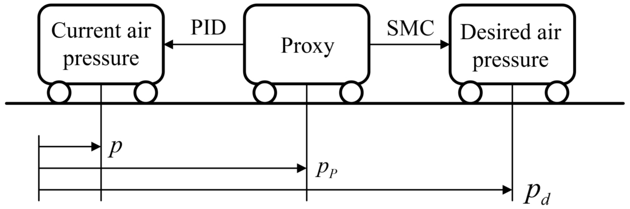
The schematic diagram of the principle of adaptive proxy-based sliding mode controller is shown in Figure 4.

Figure 4.
Schematic diagram of PSMC principle.
The actual controlled object proportional pressure-regulating valve tracks the proxy object through a PID controller, while the proxy object tracks the desired air pressure through a sliding mode controller. and represent the air pressure and expected air pressure of the virtual object, respectively. The control law to track the expected position of the virtual object is given by the sliding mode control.
The definition of the sliding surface in (7) is defined as
where represents the sign function, and F and are both control gains. When , the tracking error of the virtual object will exponentially converge to zero under the influence of the time parameter .
On the other hand, the PID control law for tracking proxy objects with actual controlled objects is expressed as
where is the position tracking error between actual and virtual objects; , and are gains of PID controller to be designed.
The auxiliary variables are defined as
where represents the tracking error between current pressure and actual pressure. Therefore, sliding mode control law and PID control law can be represented as
The sliding mode controller and PID controller counteract the proxy object, hence the following equation holds:
According to [29], we have
where and . The definition of saturation function is as shown bellow:
According to (16), we have
Combining (17), there is the following equation:
According to (16), the voltage output of the controller for proportional voltage regulation is as follows:
4.2. Stability Proof
The tracking error vector is defined as shown below:
To illustrate the stability of the controller, we introduce the following lemma.
Lemma 1.
The Lyapunov function is selected in the following manner:
According to (26), it can be known that when , and for any . Taking the derivative of V with respect to time gives
Combining (27), it can be known that
Considering , it can be known that
Combining the following inequalities:
it can be known that
and thus
When , the system enters the sliding mode. According to Equation (17), this condition is satisfied when E is in the following region:
When the value of F is sufficient to obtain , the closed-loop system is on the sliding mode surface, and S is called the sliding region. At this time, and the region is defined as
When , there is , so the control system is proven to be stable.
5. Experiments
In this section, experiments are conducted on a compliance grinding test bench designed and built by ourselves to verify the effectiveness of the proposed hysteresis model and controller.
5.1. Self-Built Test Bench
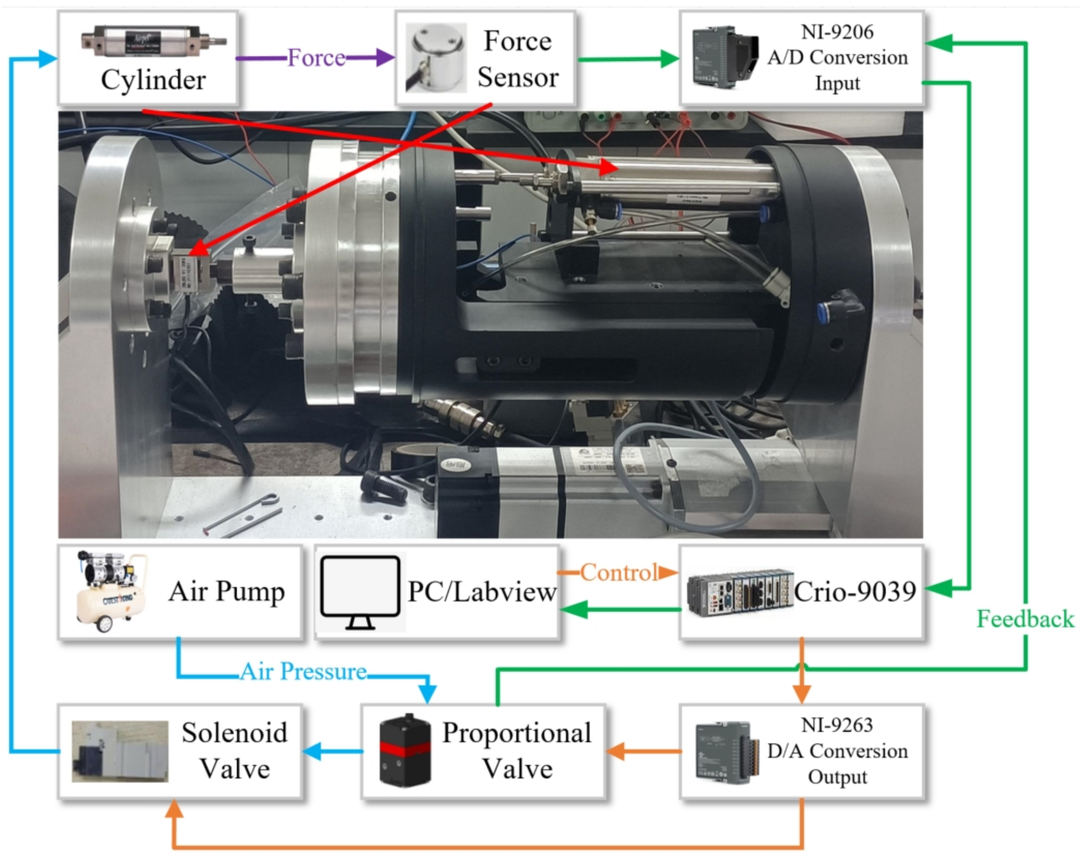
Figure 5 displays the test bench that we constructed. The compliance grinding device is fixed on a linear guiding rail. The experimental system uses a PC as the upper computer, and the control algorithms are exerted in the environment of NI LabVIEW. NI cRIO-9039 is used as a high-speed real-time lower computer, which receives instructions issued by the upper computer and sends the calculated system instructions to the lower computer in real-time. The lower computer ultimately generates the specified voltage and acts on the proportional pressure-regulating valve through the NI 9263 module to regulate the input air pressure into the cylinder. At the same time, the state value of the air pressure measured by the pressure-regulating valve in the cylinder is also fed back to the lower computer through the data acquisition module NI 9215,and the lower computer sends the feedback signal back to the upper computer.
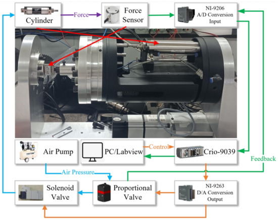
Figure 5.
Self-built compliant grinding device test bench.
5.2. Experiment Results
Experiment 1 (hysteresis compensation): This part of the experiment aims to verify the effect of our proposed hysteresis model on the rate-dependent hysteresis of the cylinder. This article compares the proposed model’s fitting performance with the traditional PIm and rate-dependent RBF-PIm models for two different frequency variations. Before the experiment begins, the parameters of the hysteresis models are identified by the parameter optimization toolbox in MATLAB/Simulink toolbox based on the data collected from experiments.
Case 1: The desired cylinder output force is set in the form of a chirp signal as
where is the end frequency, is the starting frequency, is the time of frequency changing and A, b is set to 90 and 40, respectively.
Case 2: The desired force output by the cylinder is set as
where , and b is set to 50.
In order to quantitatively compare the fitting error for cylinder hysteresis, the root-mean-squared error (RMSE) was introduced as follows:
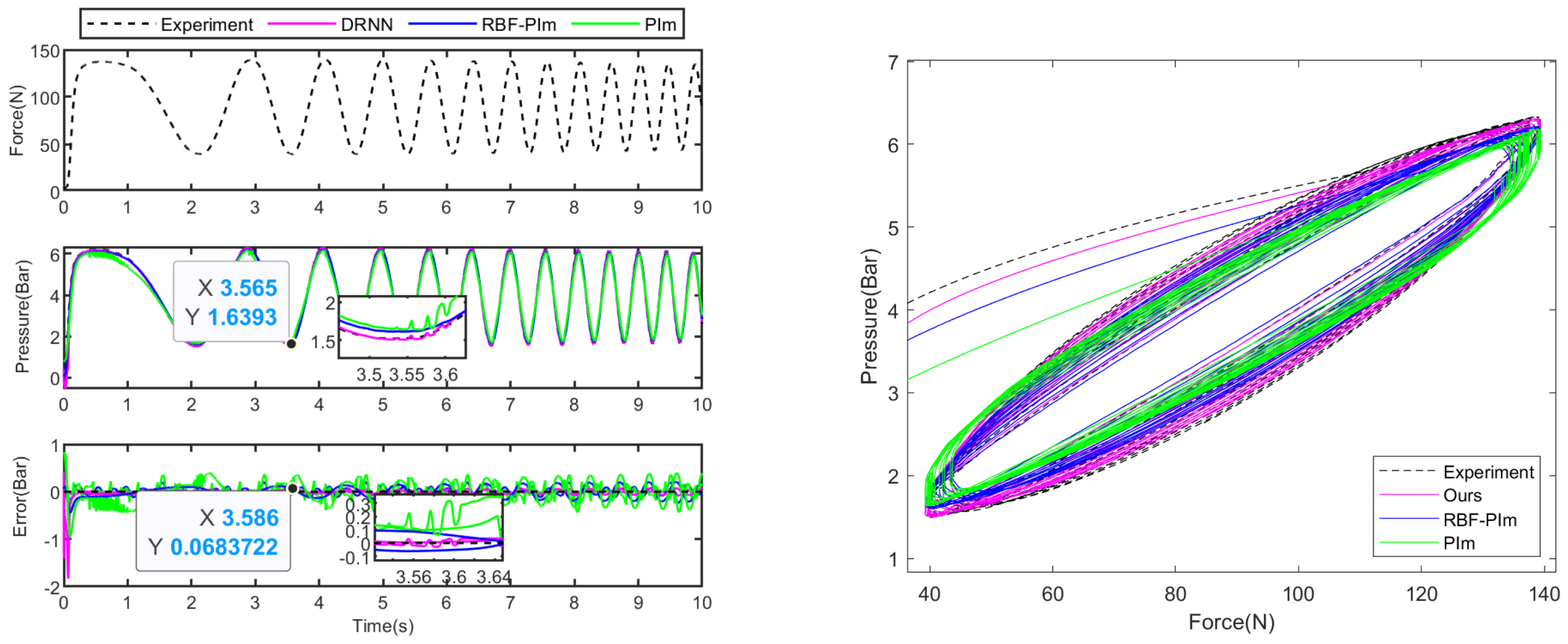
The experimental results that correspond to this are shown in Figure 6 and Figure 7. The results displayed in Figure 6 indicate that our hysteresis compensation model is more effective than two other models compensating for the force–pressure hysteresis of the cylinder with continuous variations of 2–5 Hz frequency under Case 1. Specifically, our model outperformed the rate-dependent RBF-PIm hysteresis model and traditional PIm operator hysteresis model. As shown in Table 1, the error of our proposed model measured is bar, which is smaller than bar for the RBF-PIm model and bar for the PIm model.

Figure 6.
Experimental results of Experiment 1−Case 1.
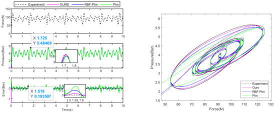
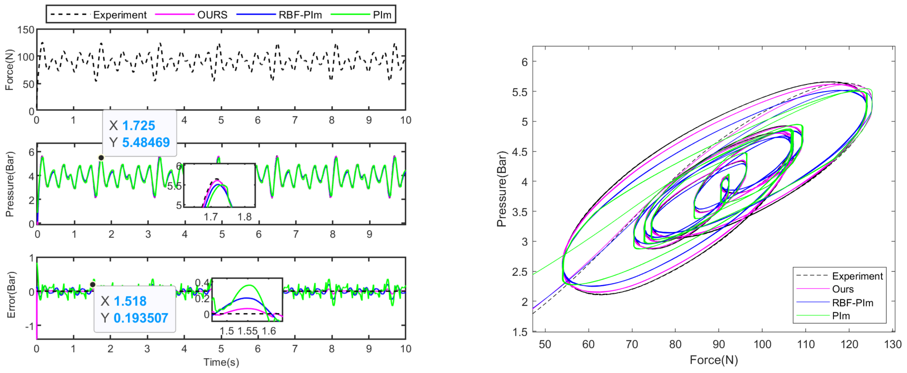
Figure 7.
Experimental results of Experiment 1−Case 2.

Table 1.
RSME for cylinder hysteresis fitting.
From Figure 7, under the random variation frequency of Case 2, our proposed model has better fitting accuracy than the rate-dependent RBF-PIm model [31,32] and the traditional PIm model. The error of our proposed model measured is bar as shown in Table 1, which is smaller than bar for the RBF-PIm model and bar for the PIm model.
It can be concluded that our proposed hysteresis compensation model fits rate-dependent hysteresis better than the traditional PIm model and RBF-PIm model used for comparison, as seen in Figure 6 and Figure 7. The dRNN stores information from previous time steps through its hidden layer states, so the dRNN-PIm model combined with dRNN and PIm models has a better fitting effect on rate-dependent cylinder hysteresis than RBF-PIm and traditional PIm models.
Experiment 2 (tracking control): In this section, four experiments were conducted to validate the effectiveness of the control algorithm.
Case 1: The desired outcome for the control system is to follow a force trajectory accurately:
Case 2: The control system is designed to follow a force trajectory as Case 1, and an additional disturbance is introduced to the system at about 1 s.
Case 3: The control system is desired to track a force trajectory in the form of a chirp signal as
Case 4: The control system is desired to track a force trajectory as
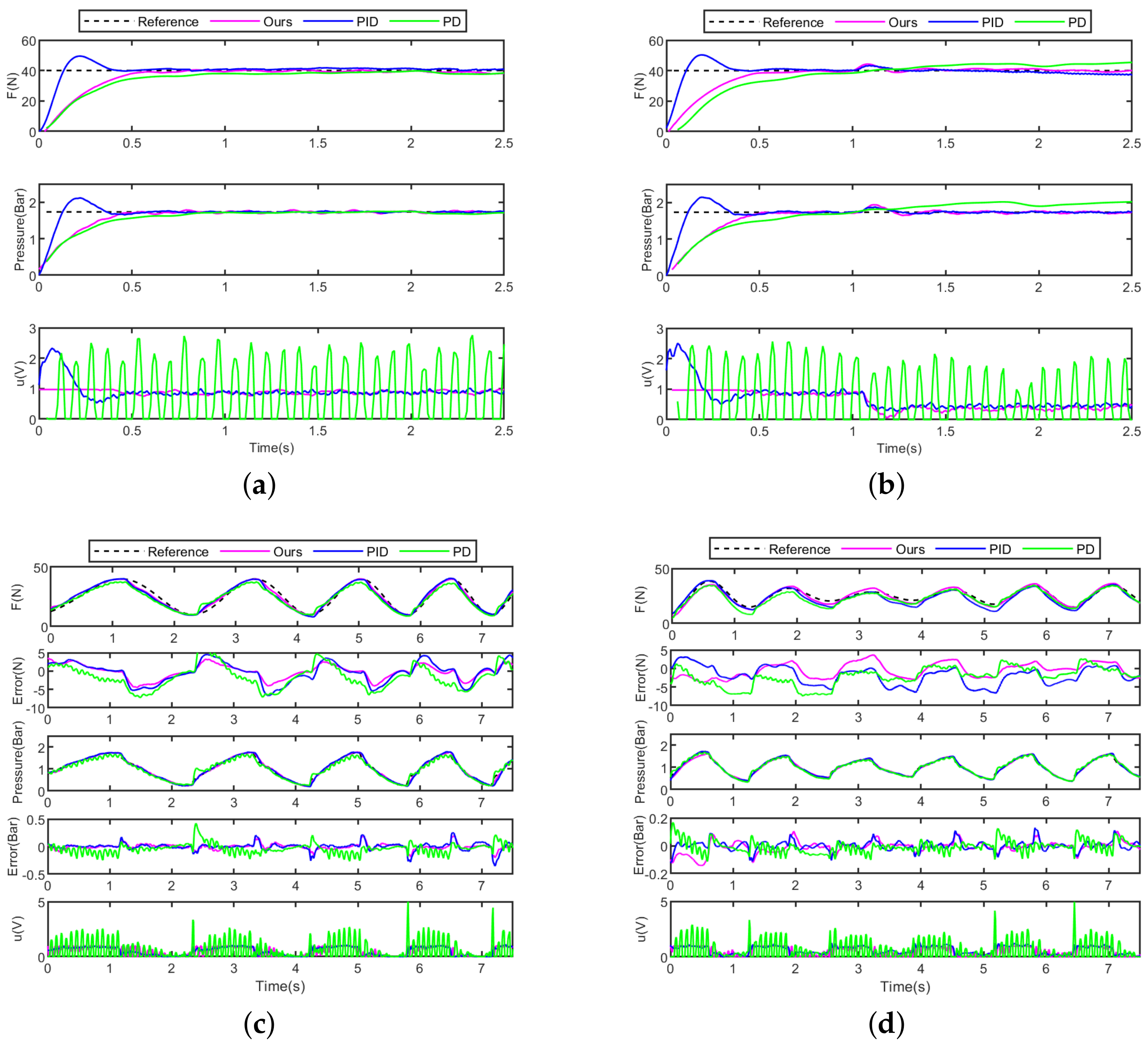
As indicated in Figure 8a, the PID controller has the shortest response time to the step output force. However, it also exhibits an overshoot, which could potentially lead to permanent damage to the workpiece surface during the grinding process. The proxy-based sliding mode controller and PD controller do not exhibit overshoot, and the response speed of the proxy-based sliding mode controller is slightly faster than that of the PD controller. In contrast, the output of the PD controller oscillates rapidly, which leads to the control energy consumed by the PD controller being much more than that of the proxy-based sliding mode controller and PID controller. It indicates that the PSMC controller has the characteristics of no overshoot, fast response speed and energy saving.
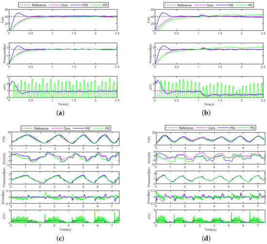
Figure 8.
Force and pressure tracking of different controllers (Experiment 2). (a) Case 1. (b) Case 2. (c) Case 3. (d) Case 4.
As for external force disturbances, we can see from Figure 8b that the proxy-based sliding mode controller and PID controller can rapidly suppress disturbances, while the PD controller exhibits a divergence phenomenon. It indicates that the PSMC controller has good robustness.
Figure 8c,d show that the three controllers track the output force of the cylinder under continuous and irregular frequency changes, respectively. It is demonstrated that for the error of tracking force, the PSMC is controlled within ±5 N, which is less than the errors of the PID controller and the PD controller. As for the accuracy of tracking pressure, the PSMC also performs better than others. The control energy consumed by PSMC is much less than the PD controller. It indicates that the PSMC controller has good robustness. The results indicate that the PSMC controller is suitable for tracking rapidly changing target air pressure or output force.
The two parts of the experiments illustrate how the hysteresis compensation and tracking control work together to control the output contact force of the compliant grinding device. Experiment 1 shows that our proposed hysteresis compensation model has a good fitting effect on rate-dependent cylinder hysteresis, and can also achieve accurate air pressure planning for situations where the end angle of the robotic arm changes rapidly and irregularly under actual working conditions, ensuring the accuracy of contact force control. The results of Experiment 2 indicate that the adopted PSMC has the characteristics of no overshoot, fast response speed, energy saving, robustness and fast-tracking. Therefore, the combination of the dRNN-PIm model and PSMC controller meets the practical control requirements of high-precision grinding.
6. Conclusions
In this paper, experimental equipment for active compliance and force control grinding is developed using a cylinder drive. Focusing on the complex random variation of cylinder output force in the actual grinding process, a rate-dependent hysteresis model of dRNN-PIm is proposed to characterize the complex nonlinear hysteresis of the cylinder and calculate the desired air pressure to maintain a constant contact force on the workpiece. Experimental results of cylinder hysteresis fitting demonstrate that in the case of chirp signal form, compared to the traditional PIm model and RBF-PIm model, the RSME of the dRNN-PIm model is reduced by and . In the case of random signal form, compared to the traditional PIm model and RBF-PIm model, the RSME of the dRNN-PIm model is reduced by and . The experimental results of cylinder hysteresis fitting show that the purposed dRNN-PIm hysteresis model can accurately fit the effect on the hysteresis loop of variable frequency input air pressure.
On this base, we utilized the proxy-based sliding mode controller to realize the fast-tracking of the desired pressure without overshooting. Additionally, the stability of the controller is proved via Lyapunov-based methods. Experimental results of air pressure tracking demonstrate that the PSMC controller exhibits smaller overshoot, less control energy and better robustness compared to the PID and PD controllers.
Finally, the control method of the compliant grinding device, which includes the proposed dRNN-PIm hysteresis compensation method and PSMC control method, has been experimentally proven to achieve high precision, no overshoot and good anti-interference fast response control of contact force.
Author Contributions
Conceptualization, Z.L. and L.S.; methodology, Z.L. and L.S.; software, Z.L.; validation, Z.L., L.S. and J.L.; writing—original draft preparation, Z.L.; writing—review and editing, Z.L., L.S., J.L., Y.Q., N.S. and L.Z. All authors have read and agreed to the published version of the manuscript.
Funding
This research was funded by the National Natural Science Foundation of China 62173192 and the Shenzhen Natural Science Foundation JCYJ20220530162202005.
Institutional Review Board Statement
Not applicable.
Informed Consent Statement
Not applicable.
Data Availability Statement
Data are contained within the article.
Conflicts of Interest
The authors declare no conflicts of interest.
References
- Zhao, X.; Lu, H.; Yu, W.; Tao, B.; Ding, H. Vision-based Mobile Robotic Grinding for Large-scale Workpiece and Its Accuracy Analysis. IEEE/ASME Trans. Mechatron. 2023, 28, 895–906. [Google Scholar] [CrossRef]
- Wu, H.; Wang, Y.; Zhang, H.; Yuan, X.; Zhou, X. Rigid Shape Matching for 3-D Robotic Grinding Measurement with Applications to Blades. IEEE Trans. Instrum. Meas. 2021, 70, 3517309. [Google Scholar] [CrossRef]
- Lu, H.; Zhao, X.; Tao, B.; Yin, Z. Online Process Monitoring Based on Vibration-Surface Quality Map for Robotic Grinding. IEEE/ASME Trans. Mechatron. 2020, 25, 2882–2892. [Google Scholar] [CrossRef]
- Li, W.-L.; Xie, H.; Zhang, G.; Yan, S.-J.; Yin, Z.-P. 3-D Shape Matching of a Blade Surface in Robotic Grinding Applications. IEEE/ASME Trans. Mechatron. 2016, 21, 2294–2306. [Google Scholar] [CrossRef]
- Ramani, S.; Salunke, A.; Ferrao, I.; Noronha, E. Automated Tile Polishing Robot. In Proceedings of the 2019 International Conference on Nascent Technologies in Engineering (ICNTE), Navi Mumbai, India, 4–5 January 2019; pp. 1–5. [Google Scholar]
- Matour, M.E.; Thormann, C.; Winkler, A. Force Controlled Deburring using a Collaborative Robot. In Proceedings of the 2022 26th International Conference on Methods and Models in Automation and Robotics (MMAR), Międzyzdroje, Poland, 22–25 August 2022; pp. 425–429. [Google Scholar]
- Xiong, R.; Lai, Z.; Guan, Y.; Yang, Y.; Cai, C. Local Deformable Template Matching in Robotic Deburring. In Proceedings of the 2018 IEEE International Conference on Robotics and Biomimetics (ROBIO), Kuala Lumpur, Malaysia, 12–15 December 2018; pp. 401–407. [Google Scholar]
- Subhashini, P.; Raju, N.V.S.; Rao, G.V. Studies on robotic deburring of machined components using a SCARA robot. In Proceedings of the 2015 International Conference on Robotics, Automation, Control and Embedded Systems (RACE), Chennai, India, 18–20 February 2015; pp. 1–6. [Google Scholar]
- Song, H.-C.; Kim, B.-S.; Song, J.-B. Tool path generation based on matching between teaching points and CAD model for robotic deburring. In Proceedings of the 2012 IEEE/ASME International Conference on Advanced Intelligent Mechatronics (AIM), Kaohsiung, Taiwan, 11–14 July 2012; pp. 890–895. [Google Scholar]
- Wu, W.; Kong, L.; Liu, W.; Zhang, C. Laser Sensor Weld Beads Recognition and Reconstruction for Rail Weld Beads Grinding Robot. In Proceedings of the 2017 5th International Conference on Mechanical, Automotive and Materials Engineering (CMAME), Guangzhou, China, 1–3 August 2017; pp. 143–148. [Google Scholar]
- Sterling, T.; Chen, H. Robotic welding parameter optimization based on weld quality evaluation. In Proceedings of the 2016 IEEE International Conference on Cyber Technology in Automation, Control, and Intelligent Systems (CYBER), Chengdu, China, 19–22 June 2016; pp. 216–221. [Google Scholar]
- Saito, K.; Miyoshi, T. Automation of polishing process for a cavity surface on dies and molds by using an expert system. CIRP Ann. 1993, 42, 553–556. [Google Scholar] [CrossRef]
- Li, P.; Li, Y.; Zha, T.; Sun, L. Research on Gridding Robots Based on Compliant Device Force Control. In Proceedings of the 2021 33rd Chinese Control and Decision Conference (CCDC), Kunming, China, 22–24 May 2021; pp. 3056–3060. [Google Scholar]
- Li, J.; Guan, Y.; Chen, H.; Wang, B.; Zhang, T. Robotic Polishing of Unknown-Model Workpieces with Constant Normal Contact Force Control. IEEE/ASME Trans. Mechatron. 2023, 28, 1093–1103. [Google Scholar] [CrossRef]
- Liu, S.; Xing, D.-P.; Li, Y.-F.; Zhang, J.; Xu, D. Robust Insertion Control for Precision Assembly with Passive Compliance Combining Vision and Force Information. IEEE/ASME Trans. Mechatron. 2019, 24, 1974–1985. [Google Scholar] [CrossRef]
- Shetty, B.R.; Ang, M.H. Active compliance control of a PUMA 560 robot. In Proceedings of the IEEE International Conference on Robotics and Automation, Minneapolis, MN, USA, 22–28 April 1996; Volume 4, pp. 3720–3725. [Google Scholar]
- Yu, Y.; Shi, R.; Lou, Y. Bias Estimation and Gravity Compensation for Wrist-Mounted Force/Torque Sensor. IEEE Sens. J. 2022, 22, 17625–17634. [Google Scholar] [CrossRef]
- Huang, T.; Liu, X.; Qiao, X. Design and dynamics control of a lightweight 6-axis collaborative robot. In Proceedings of the 2023 5th International Conference on Industrial Artificial Intelligence (IAI), Shenyang, China, 21–24 August 2023. [Google Scholar]
- Huang, Q.; Dong, C.; Yu, Z.; Chen, X.; Li, Q.; Chen, H.; Liu, H. Resistant Compliance Control for Biped Robot Inspired by Humanlike Behavior. IEEE/ASME Trans. Mechatron. 2022, 27, 3463–3473. [Google Scholar] [CrossRef]
- Zhang, X.; Chen, H.; Yang, N.; Lin, H.; He, K. A structure and control design of constant force polishing end actuator based on polishing robot. In Proceedings of the 2017 IEEE International Conference on Information and Automation (ICIA), Macao, China, 18–20 July 2017; pp. 764–768. [Google Scholar]
- Li, C.; Wang, Z.; Fan, C.; Chen, G.; Huang, T. Research on Grinding and Polishing Force Control of Compliant Flange. MATEC Web Conf. 2015, 22, 03012. [Google Scholar] [CrossRef]
- Qin, Y.; Wu, H.; Li, Z.; Sun, N.; Sun, L. Design and Analysis of a Compliant End-Effector for Robotic Polishing Using Flexible Beams. Actuators 2022, 11, 284. [Google Scholar] [CrossRef]
- Liu, J.; Li, Z.; Lin, W.; Sun, L. Predefined Performance Torque Control for a Series Elastic Actuator Based on State Observer and Disturbance Observer. In Proceedings of the 2023 42nd Chinese Control Conference (CCC), Tianjin, China, 24–26 July 2023; pp. 50–54. [Google Scholar]
- Arman, N.; Bradley, C.; Ahmadian, A.S. Design, dynamic modeling, control and implementation of hydraulic artificial muscles in an antagonistic pair configuration. Mech. Mach. Theory 2020, 153.5, 104007. [Google Scholar]
- Hassani, V.; Tjahjowidodo, T.; Do, T.N. A survey on hysteresis modeling, identification and control. Mech. Syst. Signal Process. 2014, 49, 209–233. [Google Scholar] [CrossRef]
- Nicoló, V.; Rosati, L. Analytical and differential reformulations of the Vaiana–Rosati model for complex rate-independent mechanical hysteresis phenomena. Mech. Syst. Signal Process. 2023, 199, 110448. [Google Scholar]
- Nicoló, V.; Rosati, L. Classification and Unified Phenomenological Modeling of Complex Uniaxial Rate-Independent Hysteretic Responses. Mech. Syst. Signal Process. 2023, 182, 109539. [Google Scholar]
- Li, Z.; Liu, J.; Lin, W.; Sun, L. Hysteresis Fitting for Grinding Robots Based on Compliant Device Force Control. In Proceedings of the 2023 42nd Chinese Control Conference (CCC), Tianjin, China, 24–26 July 2023; pp. 6993–6997. [Google Scholar]
- Kikuuwe, R.; Yasukouchi, S.; Fujimoto, H.; Yamamoto, M. Proxy-Based Sliding Mode Control: A Safer Extension of PID Position Control. IEEE Trans. Robot. 2010, 26, 670–683. [Google Scholar] [CrossRef]
- Chen, G.; Lou, Y. Recurrent-Neural-Network-Based Rate-Dependent Hysteresis Modeling and Feedforward Torque Control of the Magnetorheological Clutch. IEEE/ASME Trans. Mechatron. 2022, 27, 2875–2886. [Google Scholar] [CrossRef]
- Xu, Y.; Shu, F.; Yang, X.; Su, X.; Hu, B. A New Regressive RBF Neural Network Model for Rate-Dependent Hysteresis in Reluctance Actuators. In Proceedings of the 2021 13th International Symposium on Linear Drives for Industry Applications (LDIA), Wuhan, China, 1–3 July 2021. [Google Scholar]
- Edardar, M.M.; Abougarair, A.J. Tracking Control with Hysteresis Compensation Using Neural Networks. In Proceedings of the 2021 IEEE 1st International Maghreb Meeting of the Conference on Sciences and Techniques of Automatic Control and Computer Engineering MI-STA, Tripoli, Libya, 25–27 May 2021. [Google Scholar]

Disclaimer/Publisher’s Note: The statements, opinions and data contained in all publications are solely those of the individual author(s) and contributor(s) and not of MDPI and/or the editor(s). MDPI and/or the editor(s) disclaim responsibility for any injury to people or property resulting from any ideas, methods, instructions or products referred to in the content. |
© 2024 by the authors. Licensee MDPI, Basel, Switzerland. This article is an open access article distributed under the terms and conditions of the Creative Commons Attribution (CC BY) license (https://creativecommons.org/licenses/by/4.0/).