Article

A Novel Cooperative Control Strategy for Three-Degree-of-Freedom Pneumatic Parallel Mechanism

1
School of Intelligent Systems Engineering, Sun Yat-sen University, Shenzhen 518107, China
2
School of Advanced Manufacturing, Sun Yat-sen University, Shenzhen 518107, China
*
Author to whom correspondence should be addressed.
Actuators 2024, 13(3), 89; https://doi.org/10.3390/act13030089
Submission received: 21 January 2024 / Revised: 22 February 2024 / Accepted: 23 February 2024 / Published: 26 February 2024

Abstract

:
The three-degree-of-freedom (3-DoF) parallel mechanism (PM) is widely used due to its simple structure and ability to avoid coupling problems commonly found in high-DoF PMs. The conventional control approach is usually independent control for each branch of the mechanism using a PID controller, without considering the consistency among branches. This paper proposes a novel cooperative control strategy for the 3-DoF PM to achieve both synchronized and differential motion. A pneumatic actuated test rig was constructed to validate the effectiveness of the cooperative controller. The results demonstrate our control approach outperforms the PID controller. Our self-designed platform is functional and intuitive, which can be regarded as a control scheme test bench for a 3-DoF PM.

1. Introduction

In recent decades, both academia and industry have continuously shown interest in PMs, which consist of a mobile platform that is connected to a fixed base through a group of independent kinematic chains, referred to as legs [1]. The multiple parallel-legged structure allows for the distribution of load. On one hand, this special structure provides various advantages, including higher stiffness, lighter weight, greater load-carrying capacity, enhanced speed, and stable capacity, setting it apart from serial robots [2]. These benefits make PMs particularly suitable for tasks that demand high speed and accuracy, such as motion simulators, vibration suppressors, flight simulators, picking-and-placing parallel robots, and various medical applications [3,4]. On the other hand, several key issues restrict the application due to its complex structure. The parallel architecture results in an intricate dynamic model and complex singularity problems, which pose challenges in developing forward position solutions, system dynamics, and control for parallel robots compared with their serial counterparts. Furthermore, the smaller workspace of parallel robots adds more complexity to their design and operation [5].
The initial research on PMs concentrated on 6-DoF architectures, especially the well-known Stewart–Gough mechanism type serving as the foundation for the majority of the existing works related to PMs [6]. However, for most practical operations, full 6-DoF manipulators are not always necessary. Hence, there is a growing interest in the advancement of low-mobility PMs. These mechanisms not only preserve the advantages of parallel robots but also offer additional benefits such as simplified structure, easier control, and reduced design and manufacturing costs. Particularly, extensive research has been conducted on 3-DoF PMs, which are widely recognized for their simple structure and excellent motion performance. These mechanisms have been widely studied as a straightforward approach to realizing multi-DoF hybrid mechanism tools [7].
The 3-DoF PMs can be classified into four types: 3R, 3T (Delta), 2R1T, and 1R2T, where R and T denote rotational DoF and translational DoF of the end-effector, respectively. The 3R has three rotational DoFs, also known as a spherical PM, and is a flexible and highly articulated design commonly used in ankle joints for humanoid robots. For example, in [8], the paper presents a design of a 3R mechanism, ACTIVE ANKLE, that operates in an almost-spherical manner, and the experimental results demonstrate its potential as an ankle joint in a full-body exoskeleton. Recently, a new planar 3R redundantly actuated PM was proposed, and the workspace of the mechanism was solved by a numerical method [9]. The 3T refers to three translational DoFs. One well-known example is the delta robot [10], which maintains platform orientation relative to the base using passive means. The delta robot has widespread applications in various industries and has influenced the design of 3T mechanisms. In a recent study [5], a novel design of a 3T parallel manipulator was presented with simple structures and easier control design, which can be developed as prototypes for tasks like fast picking-and-placing, assembly, and 3D printing. The notation 1R2T means two of three DoFs are translations, and one is rotation as exemplified by a spatial parallel manipulator designed in [11], with wide applications in the fields of industrial robots, simulators, micro-motion manipulators, and parallel kinematics machines. The authors of [12] show a 3-DoF 1R2T PM with a forward analytical position solution and establish a dynamic model based on the Newton–Euler method for real-time control. The authors of [13] present a new 2T1R PM based on the position and orientation characteristics, and the proposed moving platform exhibits consistent performance and good dynamic characteristics. The 2R1T type has two rotational and one translational DoF, which is commonly used in motion simulators, rehabilitation robots, and ankle joints. For example, a low-cost, 3-DoF prismatic-spherical-revolute PM proposed in [14] serves as a testing platform for an unmanned aerial vehicle tethered to an unmanned surface vehicle. The authors of [15] explore a dynamics calibration method for a parallel tool head of this style and contribute to enhancing precision and performance in PM applications by a proposed decoupled polynomial model. The authors of [16] introduce a novel 2R1T PM to address typical issues in dexterity, singularities, and parasitic motions. The 2R1T PM is one of the most popular lower-DoF types. Therefore, in this paper, the control method is also tested on a self-designed 2R1T test rig.
The performance of a PM is influenced by its structural parameters, drivers, and controller [17,18]. The control system plays a crucial role in ensuring the accuracy and stability of the PM. Therefore, conducting comprehensive research and designing an efficient control system are essential for enhancing the precision and reliability of the PM.
The research on 6-DoF PMs primarily focuses on the controller due to their complex coupling properties and intricate kinematics, which affect motion performance and increase control difficulty. Numerous control methods have been proposed to achieve decoupling. Guan and Plummer proposed an accelerated decoupling control strategy based on modal space for a 6-DoF electrohydraulic shaking table [19]. Plummer also presented a model-based motion control method for multi-axis servo hydraulic shaking tables [20]. Zhang et al. achieved decoupling for a multi-axis seismic testing table using servo control and offline iterative control based on a dynamic model [21]. As for 3-DoF PMs, the coupling issue is considerably simplified due to their structures. Consequently, the researchers have primarily focused on kinematics and dynamics, which is the factor that mainly decides the effectiveness of control system, while neglecting the study of control methods themselves.
The control of parallel manipulators involves two fundamental strategies. One is model-free control, which operates without an explicit model of the system. The proportional-integral-derivative (PID) controller family (including PID, PD, and enhanced PID) are the most common schemes for low-DoF PMs. In [22], PID control is employed for a 3-DoF parallel manipulator, and the tuning of the PID controller is conducted using the Zeigler–Nichols method and a genetic algorithm. A variable-parameter PID controller optimized by a genetic algorithm controller is proposed in [23] to enhance the control precision and robustness of the existing PID controller for a 3-DoF parallel robot. The classical PID and fractional-order PID controls are utilized to enhance the tracking performance of the Maryland manipulator [24]. Ref. [25] applies neural networks to the kinematic calibration of 3-UPS shipborne stabilized platforms. The control methodology utilizes transfer learning to compensate for pose errors and improve motion accuracy. A 2-DoF 5R PM is proposed in [26], and the control system is based on closed-loop PID controller to improve the accuracy. The other is model-based control, such as adaptive control, iterative learning control (ILC), and sliding-mode control, which relies on the system model to design the control law. The study in [27] introduces an adaptive control scheme for a 3-DoF parallel manipulator, based on an innovative dynamic model of relevant parameters. In [28], an adaptive fuzzy sliding mode controller (AFSMC) is designed and implemented for a 3-DoF parallel manipulator. The authors of [29] develop an inverse dynamic controller (IDC) for the 3-UPU motion simulator within the joint space, effectively mitigating the inherent nonlinearities and coupling of the robot, consequently enhancing the overall control performance. It addresses a method where the internal force term can be linearly separated into a regression matrix and a parameter vector containing the estimated errors. Moreover, to improve the control performance, many researchers have combined multiple methods with the PID controller. The control system in [17] is based on the joint space and task space of the mechanism and employs an iterative learning method to enhance the performance of the PD controller. The passivity-based control proposed in [2] incorporates gravity compensation in the PD controller.
The two aforementioned control approaches primarily focus on controlling each actuator in PMs. However, due to the high nonlinearity, the strongly coupled nature, and the difficulty in accurate modeling, these methods cannot guarantee good controller performance. Hence, exploring more effective control methods is one of the primary considerations in PM applications, intending to achieve the advantageous property and additional potential [7].
Su et al. [30,31] find that the absence of inter-actuator communication in control loops leads to uncorrected errors and unnecessary coupling errors, which means the high-precision motion of parallel manipulators depends not only on the positional accuracy of each actuator but also on the synchronized positioning of all actuators. As for synchronous control, a cross-coupling controller is introduced to achieve the synchronization of motors in [32]. Inspired by that, [7] integrates cross-coupling techniques into a PD controller, proposing a simple synchronous control method for setpoint position control of parallel manipulators, and [33] develops a new synchronization control strategy based on cross-coupling control for a 3-DoF planar parallel robotic manipulator. L. Ren et al. [34] have mentioned the tracking control of planar parallel robots can be addressed as a synchronous control problem due to the closed-loop structure. They have successively proposed a series of synchronous control algorithms for PMs [35,36], and an evaluation of four controllers of a 3-DoF parallel robot in [34] is conducted, including PI control, adaptive synchronized (A-S) control, conventional PID control, and adaptive control. The results show the synchronized-type control approaches have better tracking accuracy.
These above studies have collectively demonstrated that it is necessary to consider synchronous error among individual actuators for the control of PMs. Compared with electrical systems, pneumatic systems exhibit stronger inherent nonlinearity. Coupled with differences in physical characteristics and friction of each actuator, achieving motion consistency and synchronous control in pneumatic systems becomes significantly more essential. Therefore, this paper presents a study, from the mechatronic point of view, on the control of a pneumatic 3-DoF PM. Our first contribution is to develop a novel control method about synchronous motion. The proposed cooperative control scheme is model-free control based on signal cross-coupling, considering tracking error and synchronous error. Simulations and experiments were performed to validate this strategy over a virtual model and actual prototype. Additionally, our self-designed pneumatic platform can be treated as a control scheme test bench, which allows the testing and comparison of various control methods for 3-DoF PMs.
The rest of the paper is organized as follows. Section 2 presents our experiment settings. Section 3 illustrates mathematical modeling including the kinematics of this PM and pneumatic system modeling. Our control system is analyzed in Section 4. Detailed control strategy and controller design are explained in Section 4.1 and Section 4.2, respectively. The experiments and discussions are displayed in Section 5, followed by conclusions in Section 6.

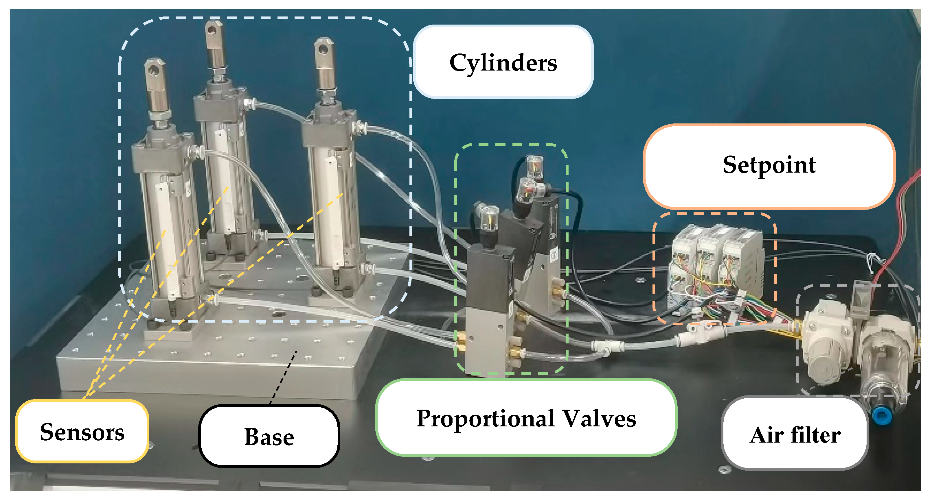
2. Experiment Settings

The test rig setup is shown in Figure 1. The main part of the platform consisted of a base and three cylinders distributed as an equilateral triangle. The tops of the cylinders formed a 3-DoF moving plate with two rotational DoFs and one translational DoFs. Our self-designed test rig was a 2R1T type of 3-DoF PM.
Each cylinder had a total stroke of 100 mm with the midpoint as the initial point and a motion range of ±50 mm. The plane formed by the vertices of the three pods could be regarded as a movable platform. The base had multiple assembly holes, allowing for cylinders to be arranged in different configurations and further research for movable platforms. The three cylinders were pneumatic actuators with position sensors in parallel. A pressure sensor was used to measure the piston side pressure of the actuator. The key hardware components are shown in Table 1. The platform was designed based on the principles of mechatronics, which integrates mechanical, electrical, and control systems. It serves as an intuitive and cost-effective robotic platform to test control methods.
The mechanical model of this platform was built using Simscape 4.5, a multi-body mechanical simulation tool in Simulink®. The mechanical properties of the rigid bodies were defined in Autodesk Inventor 2021®, then uploaded to Simscape to create a 3D visualization. In subsequent experiments, the interaction between software and hardware was achieved through co-simulation using MATLAB®/Simulink® and NI VeriStand® 2020.

3. Modeling

This section explains the modeling of kinematics and the actuated system. The transformation between position and posture was computed through the forward and inverse kinematics. The pneumatic system modeling established the relationship between the air supply and the provided power.

3.1. Kinematics

As shown in Figure 2a, the initial positions of the cylinders are labeled as A1, A2, and A3, and the centroid of the triangle A1A2A3 formed by these three points is marked as O1. After moving, the positions of the cylinders are labeled as B1, B2, and B3, and the centroid of the triangle B1B2B3 formed by these three points, as well as the end-effector’s position, is marked as O2.
For this 3-DoF PM, the state of the end-effector can be simply and uniquely expressed using three variables. These three DoFs correspond to rotation about the x1-axis, rotation about the y1-axis, and translation along the z1-axis. Accordingly, the end-effector’s pose can be represented as (α, β, h), where α and β are the x–y Euler angles, and h is the height of the centroid’s vertical translation. The goal of kinematics is to establish a bi-directional mapping between the positions of the prismatic joints (h1, h2, h3) and the state of the end effector (α, β, h).
Taking O1 as the origin, the world frame O1-x1y1z1 (frame {O1}) is established. The vector from the starting point A1 to the end point B1 is defined as A 1 B 1 , and so on. The vector from the origin O1 to a specific point is represented using single-point coordinates, such as A1(r; 0; 0). The coordinates of the points A1, A2, and A3 in frame {O1} can be expressed based on Figure 2b. Then, combined with the elongation lengths h1, h2, and h3 of the three cylinders, the coordinates of the points B1, B2, and B3 in frame {O1} can be obtained. Then, O2 can be represented as
O 1 O 2 = 1 3 ( O 1 B 1 + O 1 B 2 + O 1 B 3 ) = ( 0 ; 0 ; h 1 + h 2 + h 3 3 )
The detailed coordinates of the key vectors and points are shown in Table 2. The relationship between h1, h2, h3, and h can be established by Equation (1):
h = h 1 + h 2 + h 3 3
To establish the relationship between h1, h2, h3, and α, β, the unit normal vector of the plane φ will be expressed using α, β, and h1, h2, h3, respectively.
Rotation about the x-axis by α and rotation about the y-axis by β can be represented using rotation matrices, respectively:
R x = 1 0 0 0 cos α sin α 0 sin α cos α , R y = cos β 0 sin β 0 1 0 sin β 0 cos β
Based on the x–y Euler angles in Figure 2c, the orientation of the end-effector can be represented using a rotation matrix:
R x y = R x R y = [ x r , y r , z r ] = cos β 0 sin β sin α sin β cos α sin α cos β cos α sin β sin α cos α cos β
where the unit normal vector zr can be obtained. Meanwhile, the normal vector n can also be expressed using B 1 B 2 , B 2 B 3 , and B 3 B 1 :
n = B 1 B 2 × ( B 3 B 1 ) = B 2 B 3 × ( B 1 B 2 ) = B 3 B 1 × ( B 2 B 3 ) = 3 2 r 2 h 1 + h 2 + h 3 3 ( h 2 h 3 ) 3 r
which leads to the unit normal vector nu,
n u = n n = 1 ( 2 h 1 + h 2 + h 3 ) 2 + ( 3 ( h 2 h 3 ) ) 2 + 9 r 2 2 h 1 + h 2 + h 3 3 ( h 2 h 3 ) 3 r
The unit normal vectors of the same plane φ follow nu = zr (cosαcosβ > 0 and r > 0, so nu = −zr is excluded):
n u = z r = sin β sin α cos β cos α cos β = 2 h 1 + h 2 + h 3 ( 2 h 1 + h 2 + h 3 ) 2 + ( 3 ( h 2 h 3 ) ) 2 + 9 r 2 3 ( h 2 h 3 ) ( 2 h 1 + h 2 + h 3 ) 2 + ( 3 ( h 2 h 3 ) ) 2 + 9 r 2 3 r ( 2 h 1 + h 2 + h 3 ) 2 + ( 3 ( h 2 h 3 ) ) 2 + 9 r 2
As |α| is too small to reach cosα = 0 and so is |β|, dividing the first and second rows of the vectors by the third row separately in Equation (8), simplified expressions can be obtained:
2 h 1 + h 2 + h 3 3 r = tan β cos α 3 ( h 2 h 3 ) 3 r = tan α
which can be expressed in matrix form combining Equation (2):
A H = tan β cos α tan α h ,   where   A = 2 3 r 1 3 r 1 3 r 0 3 3 r 3 3 r 1 3 1 3 1 3 , H = h 1 h 2 h 3
Forward kinematics are used to obtain (α, β, h) when (h1, h2, h3) is known:
α = arctan ( 3 ( h 2 h 3 ) 3 r ) β = arctan ( cos α ( 2 h 1 + h 2 + h 3 ) 3 r ) = arctan ( 2 h 1 + h 2 + h 3 3 ( h 2 h 3 ) 2 + 9 r 2 ) h = h 1 + h 2 + h 3 3
Inverse kinematics are used to obtain (h1, h2, h3) when (α, β, h) is given, which can be calculated from Equation (9):
H = A 1 tan β cos α tan α h ,   where   A 1 = r 0 1 1 2 r 3 2 r 1 1 2 r 3 2 r 1

3.2. Pneumatic System Modeling

As the most commonly used actuator, pneumatic cylinders can serve as a superior alternative to electrical or hydraulic actuators for certain types of applications. This chapter presents the modeling of the pneumatic cylinder and valve. The model of the dual-action pneumatic actuator system controlled by a proportional valve follows well-established procedures [37]. The pneumatic system is shown in Figure 3. Ps represents the pressure of the gas source. Patm denotes the atmospheric pressure. Au and Ad refer to the piston areas of upper chamber with a rod and lower chamber without a rod. Pu and Pd correspond to the pressures in the upper and lower chambers, respectively. Ar signifies the surface area of the piston. All these parameters are labeled accordingly in Figure 3.

3.2.1. Pneumatic Cylinder Model

Assuming it is an ideal gas and there is no air leakage, the dynamic equation of this actuator can be written via Newton’s second law:
( M L + M P ) x ¨ + C x ˙ + F f = P d A d P u A u P a t m A r
where x represents the piston displacement, and ML and MP are the external mass and the piston-rod mass, respectively. C is the viscous friction coefficient, and Ff is the Coulomb friction force.

3.2.2. Valve Model

The flow rate is determined by the proportional valve’s orifice area, which in turn affects the pressure of each chamber. Here Sanville’s flow formula [38] is adopted:
Q m = A v p i 2 k R T ( k 1 ) P o P i 2 k P o P i k + 1 k P o P i > C t A v p i 2 k + 1 2 k 1 2 k R T ( k + 1 ) P o P i < C t
where Av is the cross-sectional valve orifice area (mm2), T is the absolute temperature, R is the gas constant, and Ct is the critical pressure ratio. Pi and Po represent the pressure of valve’s inlet and outlet port. For our model, Pi = Ps and Po = Pd when the piston undergoes positive displacement, while Pi = Pu and Po = Patm when the piston undergoes negative displacement.

4. Design of Controller

A parallel manipulator owns multiple variable-length actuators, and the motion of mobile platform depends on the extension and retraction of each actuator. The cooperative coordination of actuator lengths enhances the mobile platform’s ability to track complex trajectories with higher precision.
Our control strategy not only achieves position control for each actuator but also ensures synchronized motion among all the actuators. Unlike conventional control methods that focus solely on controlling the final positions of individual actuators, this paper proposes a novel control strategy and establishes a cooperative controller specifically designed for a 3-DoF PM. This chapter presents our control approach from the perspectives of control strategy and controller design.

4.1. Control Strategy

Assuming a PM with n actuators, there were two control goals. One goal was to achieve precise position tracking for each actuator. Another goal was to ensure synchronized motion among all the actuators, aiming for consistency in their movements. This can be represented by Equation (14):
p i = p i d p 1 t p 1 d t = p 2 t p 2 d t = = p n t p n d t , i = 1 , 2 , , n
where p i t and p i d t represent the actual and desired position signals of actuator i, respectively.
The fundamental principle underlying the goals is that by satisfying the condition stated in Equation (14), the PM can achieve its target position while moving in a synchronized mode. As a result, it ensures consistency among the actuators and reaches the desired pose of the mobile platform.
According to the structure of the PM, ensuring synchronization between adjacent actuators is essentially sufficient to achieve overall synchronization. Therefore, the communication between adjacent actuators is more useful than that between non-adjacent ones. Based on this idea, we can decompose the synchronous position goals in Equation (15) into the following sub-objectives:
p 1 t p 1 d t = p 2 t p 2 d t , , p n 1 t p n 1 d t = p n t p n d t , p n t p n d t = p 1 t p 1 d t
Similar to conventional methods, the position error of the ith actuator is defined as Equation (16):
e i t = p i d t p i t
These sub-goals can be expressed as a set of linear synchronization functions:
f ( p 1 t , p 2 t ) = p 2 t p 2 d t p 1 t p 1 d t = e 1 t p 1 d t e 2 t p 2 d t f ( p n 1 t , p n t ) = p n t p n d t p n 1 t p n 1 d t = e n 1 t p n 1 d t e n t p n d t f ( p n t , p 1 t ) = p 1 t p 1 d t p n t p n d t = e n t p n d t e 1 t p 1 d t
Instead of regarding each actuator as an individual, the designed cooperative error is based on inter-actuator communication, including the average error and difference error.
The average error ε i A is defined as the mean value of the position errors between two adjacent actuators:
ε i A ( t ) = p i d t p i t 2 + p i + 1 d t p i + 1 t 2
The difference error ε i D is defined as the difference value between two adjacent actuators:
ε i D ( t ) = p i + 1 t p i + 1 d t p i t p i d t
Based on Equations (15)–(17), Equations (18) and (19) can be written as follows:
ε i A ( t ) = e i t + e i + 1 t 2 ε i D ( t ) = p i d t e i + 1 t p i + 1 d t e i t
The equations can be expressed in a generalized matrix form in Equation (21):
ε A ( t ) = C 1 e t ε D ( t ) = C 2 e t
where ε A = ε 1 A , ε 2 A , , ε n A T n × 1 , ε D = ε 1 D , ε 2 D , , ε n D T n × 1 , e = e 1 , e 1 , , e n T n × 1 and C 1 , C 2 n × n . The bold variables represent vectors or matrices in this article.
C 1 = 1 2 · 1 1 1 1 1 1 , C 2 = p 2 d p 1 d p n d p n 1 d p n d p 1 d
From the above equations, it can be observed that our control objective is to make ε A and ε D tend to 0 as t → ∞. That means in the control system, the control signals are designed as the average value and the difference value of the position errors between adjacent actuators. These also provide evidence that our control method is feasible to enable the achievement of synchronized motion among the actuators.

4.2. Cooperative Control System

Based on the aforementioned control approach, a controller is designed for our self-designed 3-DoF pneumatic PM. This control system is divided into two components: a signal selection system and a cooperative controller. Additionally, the entire control process is demonstrated by showcasing the interaction between the control system and the mechanical system.

4.2.1. Signal Selection

Signal selection analysis is an important step in control system design, which involves choosing the appropriate signals for analysis from multiple input signals. In this process, position signal, mean signal, and difference signal are common options for input signals. For a 3-DoF mechanism, there will be nine possible options including three position signals (x1, x2, and x3), three mean signals (a12, a23, and a31), and three difference signals (e12, e23, and e31). Normally, three given signals are sufficient for subsequent control, but it is necessary for them to be linearly independent rather than arbitrary. Therefore, in this section, matrices are utilized to summarize the selection process from the nine signals.
The nine input signals can be represented as a set 𝓒 = {a12, a23, a31, e12, e23, e31, x1, x2, x3}. Matrix T is the selection matrix obtained from mathematical relationships:
T = 0.5 0 0.5 1 0 1 1 0 0 0.5 0.5 0 1 1 0 0 1 0 0 0.5 0.5 0 1 1 0 0 1 = t 1 t 2 t 3 t 4 t 5 t 6 t 7 t 8 t 9 9 × 3
Matrix Cs consisting of three input signals can be written as
C s = c i c j c k = t i t j t k x 1 x 2 x 3
where ci, cj, ck ∈ 𝓒, ij, ik, jk.
Let Ts = [ti; tj; tk]T; if Ts is linearly independent, the three signals in Cs are satisfied for subsequent control. At the same time, the remaining six signals of the nine can also be determined. For convenience, position signals are served as the final input signals for the subsequent control system.

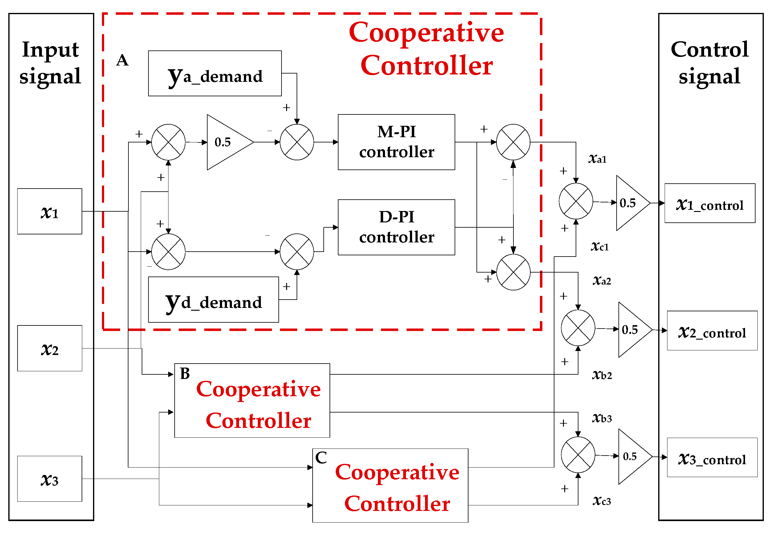
4.2.2. Cooperative Controller

Figure 4 presents our proposed control strategy. Every two branches require one cooperative controller. For one cooperative controller, the real demand signals are the average (ya-demand) and difference (yd-demand) between two branches’ demand positions. Controlling the average position is to ensure each branch reaches its desired position, and controlling the position difference is to achieve consistent motion of the two branches.
For the 3-DoF platform, three feedback position values collected from sensors are used as actual input signals, and there are three steps to obtain the control signals. First, every two input signals are grouped in pairs. Averaging and differencing operations are performed for each group of input signals. Then, the processed signals pass through a PI controller individually, after taking the difference with the corresponding demand signals. Finally, control signals are acquired by numerical operations of combined results from each group. It should be noted that the parameters of each group’s two PI controllers can be different due to each group being composed of different branches.
After the aforementioned signal allocation, our controller not only achieves demand signal tracking for each branch but also ensures the consistency of movement for each branch. The cooperative controller considers the coupling effect between different chains in the PM through the construction of cooperative error.

4.2.3. Control System Framework

Figure 5 demonstrates the entire control process and the real-time data flow in our self-designed 3-DoF platform. The signal selection part provides demand position signals, and actual position signals are provided by the position sensors installed on the side of the cylinder. In the cooperative controller part, the control signals are computed and then outputted to the pneumatic system. The PXIe chassis and data acquisition boards are responsible for collecting and transmitting data and serve as a bridge connecting software and hardware. Real-time data transmission and real-time modification of instructions can be achieved through NI Veristand® 2020. The subsequent experiments were conducted according to this framework diagram.

5. Results and Discussions

This chapter focuses on results and analysis. The simulations were conducted within MATLAB®/Simulink® to verify the feasibility of our models. The experiments were carried out on a 3-DoF pneumatic platform to evaluate the performance of the PID controller and the proposed cooperative controller. Data were acquired using the JYTEK® PXIe data acquisition board combined with software NI VeriStand® 2020 and plotted in MATLAB® R2020b.

5.1. Validity of Pneumatic System Model

A simulation model for one pneumatic chain was constructed in Simulink® according to Equations (10)–(13), (21) and (22). To validate the model’s accuracy, a comparative analysis was conducted between the simulation results in Simulink® and the physical experiments on our self-designed test rig. The simulation and physical experiments employed a PID controller with identical parameters. The demand position for one actuator was a square signal with an amplitude of 30 mm. There were three groups of experiments, and the frequencies of the signals were 0.1 Hz, 0.3 Hz, and 0.5 Hz. The comparison results are shown in Figure 6. It is illustrated that the simulation and physical experiments had similar dynamic response performances. The rise time and settling time were essentially consistent, particularly at 0.1 Hz and 0.3 Hz. Their steady-state performances were also similar, with steady-state errors approaching zero around the same time.
The simulation results matched the physical experiments, indicating that the simulation model for one cylinder was essentially accurate, especially for 0.1 Hz and 0.3 Hz. As for 0.5 Hz, the disparity between them may stem from two factors. One factor pertains to the imprecision of parameters in the simulation model, including the inaccuracy in the manual; another factor involves the inadequacy of the sensor’s sampling frequency during data collection. In addition, it can be observed that the system exhibited better tracking performance at a frequency of 0.1 Hz. However, as the frequency increased to 0.5 Hz, there was a noticeable phase lag.

5.2. Performance of Controllers

To validate the cooperative controller’s effectiveness, comparative experiments were conducted on our 3-DoF test rig, comparing its performance with that of a PID controller as a baseline experiment.
In the following, we compared the tracking performance of these two controllers under the given poses of the end-effector. The cylinder had a travel range of ±50 mm along the z-axis. To mitigate the influence of friction, ±30 mm was chosen as the maximum and minimum displacement for the experiments. Hence, the range of rotational angles of the moving plate was (−22.63°, 22.63°). The positive direction was defined when the rod extended, and the negative direction was defined when it retracted. The demand pose of the end plate was set to translational motion along the z-axis to ensure synchronous movement of each rod, which provided a clearer comparison of end-effector tracking accuracy and position errors. That meant that in the desired pose, both α and β were set to zero, while h was a square wave with an amplitude of 30 mm. Considering the response frequency of this pneumatic test bench, as observed in Figure 6, the frequency of the demand signal was set to 0.1 Hz. The demand position signals for each piston were calculated using Equation (11). In this case, the three demand position signals were computed to be the same as the demand h signal. The actual pose of the end-effector could not be measured directly due to hardware limitations. Through position sensors on the cylinders, the actual pose was derived based on mathematical modeling. The acquisition frequency of the sensor was 4 Hz.
For the baseline experiment, the PID block was constructed based on Equation (25), and the three parameters were manually adjusted to achieve the best performance.
u t = K P ( e t ) + 1 T t 0 t e t d t + T D d e t d t
The three pneumatic chains were controlled independently. Input signals were directly fed to the three cylinders through the PID controllers. It is important to note that our 3-DoF pneumatic test rig consisted of three identical sets of valve-controlled cylinder circuits. Consequently, the parameters in the three PID controllers were set to be identical.
The experiment for the cooperative controller used the same input signals and test bench as those for the PID controller. The main difference from the PID controller was that the proposed controller took into account the communication between each pair of chains to mitigate the coupling effect and achieve synchronous motion. The input signals were processed according the procedure described in Section 4.2. The parameters were also adjusted manually. The pose data of the end-effector were recorded, and the results are depicted in Figure 7.
Figure 7a presents the centroid’s height of the end-effector, and the right side presents a local zoom-in at the amplitude of ±30 mm. It can be observed that the end-plate could largely follow the demand signals for both controllers. The delay was primarily due to the strong nonlinear characteristics of the pneumatic system. In comparison with the PID controller, our controller had a slower response than the PID controller when the rod was retracted. However, it consistently exhibited better tracking accuracy, whether the rod was extended or retracted. Figure 7b indicates that the Euler angle α closely aligned with the desired α, and the control accuracy of both controllers was around 0.01 radians. As for Euler β in Figure 7c, there was a significant difference in precision between the two controllers. For our controller, the error appeared as a spiky protrusion with a value around 0.03 radians, which was about half that in the PID controller. Also, our controller demonstrated a smaller steady-state error and a shorter settling time for Euler β.

5.3. Discussions

In our experiments, the demand pose involved translational motion along the z-axis, where the end-effector’s tracking control could be viewed as the synchronous motion control of the three cylinders. To provide a more comprehensive comparison of the two controllers’ performance, the position average error and difference error between each pair of cylinders were contrasted. The desired average error and difference error were both zero in this synchronous motion. The results are presented in Figure 8 and Figure 9. The right subplot in Figure 8 is a local zoom-in to facilitate the finer details. The protrusions in Figure 8 and Figure 9 correspond to step signals changing in direction. These two figures reveal our controller results in a smaller average and difference error between every two actuators with a shorter settling time compared with that of the PID controller. Moreover, the three groups of errors of the cooperative controller were more similar than those of the PID controller. These also meant that the movement of the three cylinders was more synchronous with the consideration of the coupling effect among these branches.
From the contrastive results, the significance of information interaction between each two chains in a PM could be demonstrated. For the baseline experiments, the three PID controllers worked independently for each branch. The control signal was the difference between the demand position and the feedback of the actual position in each control loop. Therefore, this controller’s effect was to ensure that the position of each piston followed its own demand signal, without considering the relations among different branches. However, in our proposed approach, every two branches required one cooperative controller. For each cooperative controller, the two input signals were the feedback position signals from sensors. Unlike the control signals of the PID controller, those of the cooperative controller were the position average and the position difference between two branches. Controlling the average position could ensure each branch reached its desired position, and controlling the position difference was able to achieve consistent motion of the two branches. This implied that our controller could enhance the motion consistency between the branches of the PM, while the PID controller without signal interaction failed to do so.

6. Conclusions

This paper investigates the performance of a novel cooperative control strategy for 3-DoF PMs. A cooperative controller was designed to achieve both position control and synchronous control simultaneously. A novel error, named cooperative error, was proposed combining both average error and difference error to enable inter-chain communication in PMs. A 3-DoF pneumatic test bench was also built along with its corresponding simulation model to facilitate both simulation and physical experimentation. The comparative experiments were performed between the cooperative controller and the baseline controller to verify the proposed control strategy. The two controllers were tested through a position synchronization experiment. The results showed our controller had better tracking accuracy, smaller pose errors, and a shorter settling time. For the PID controller, the asynchrony between every two cylinders could reach up to ±10 mm, while for our cooperative controller, the magnitude of these fluctuations was reduced almost by half. As for the average and difference between every two cylinders, our controller yielded a smaller disparity and exhibited a more stable and consistent feature when approaching targets.
  • Additionally, this research implemented the complete mechatronic design of a low-cost 3-DoF parallel robot that integrates mechanical, electrical, and control systems. Our self-designed parallel system with a simple and open architecture can serve as a versatile test bench for validating and comparing various methods for the 3-DoF mechanism. This can provide a controlled environment for evaluating the performances of different control algorithms under different conditions. The primary contributions of this paper can be summarized as follows. The paper introduces a novel control mechanism aimed at achieving synchronous motion and improving tracking accuracy for 3-DoF PMs.
  • Unlike traditional control methods, the proposed mechanism designed a cooperative error to incorporate inter-chain communication and reduce coupling effects in PMs.
  • An intuitive 3-DoF pneumatic test bench for the control methods was constructed, and comparisons with experiments with the baseline controller showed the proposed method had better tracking performance.
  • In the future, it is expected to continue evaluating this cooperative controller. It is noticed that adjusting the controller for one cylinder has a certain degree of influence on the other cylinders. Subsequent research will delve into this effect and find the potential trends. Moreover, it is aimed to generalize this control approach for higher-DoF PMs, or at least, this control strategy can be employed in the motion of certain DoFs. What is more, a self-designed plate will be installed on the cylinder of the 3-DoF platform to support further research on PMs. The base of our platform is connected with an automated guided vehicle (AGV), which provides more DoF and potential research aspects.

Author Contributions

Conceptualization, Q.H. and B.D.; methodology, Q.H. and B.D.; software, Q.H.; validation, Q.H.; formal analysis, Q.H. and G.H.; investigation, Q.H.; data curation, Q.H.; writing—original draft preparation, Q.H. and G.H.; writing—review and editing, Q.H., G.H. and B.D.; supervision, B.D. and G.F.; funding acquisition, B.D. and G.F. All authors have read and agreed to the published version of the manuscript.

Funding

This work was supported by the National Natural Science Foundation of China, grant numbers 52105079 and 62103455.

Data Availability Statement

The data presented in this study are available on request from the corresponding author.

Conflicts of Interest

The authors declare no conflicts of interest.

References

  1. Merlet, J.P. Parallel Robots; Springer Science & Business Media: Berlin/Heidelberg, Germany, 2006; Volume 128. [Google Scholar]
  2. Vallés, M.; Díaz-Rodríguez, M.; Valera, Á.; Mata, V.; Page, Á. Mechatronic development and dynamic control of a 3-DOF parallel manipulator. Mech. Based Des. Struct. Mach. 2012, 40, 434–452. [Google Scholar] [CrossRef]
  3. Gao, M.; Zhang, X.; Liu, H. Experiment and kinematic design of 3-RRR parallel robot with high speed. Robot 2013, 35, 716–722. [Google Scholar] [CrossRef]
  4. Zhang, X.; Zhang, X.; Chen, Z. Dynamic analysis of a 3-RRR parallel mechanism with multiple clearance joints. Mech. Mach. Theory 2014, 78, 105–115. [Google Scholar] [CrossRef]
  5. Zou, Q.; Zhang, D.; Zhang, S.; Luo, X. Kinematic and dynamic analysis of a 3-DOF parallel mechanism. Int. J. Mech. Mater. Des. 2021, 17, 587–599. [Google Scholar] [CrossRef]
  6. Stewart, D. A platform with six degrees of freedom. Proc. Inst. Mech. Eng. 1965, 180, 371–386. [Google Scholar] [CrossRef]
  7. Niu, X.-M.; Gao, G.-Q.; Liu, X.-J.; Bao, Z.-D. Dynamics and control of a novel 3-DOF parallel manipulator with actuation redundancy. Int. J. Autom. Comput. 2013, 10, 552–562. [Google Scholar] [CrossRef]
  8. Kumar, S.; Bongardt, B.; Simnofske, M.; Kirchner, F. Design and kinematic analysis of the novel almost spherical parallel mechanism active ankle. J. Intell. Robot. Syst. 2019, 94, 303–325. [Google Scholar] [CrossRef]
  9. Zhang, J.; Wang, D.; Song, Z.; Guo, H.; Liu, R.; Kou, Z. Workspace analysis and size optimization of planar 3-DOF redundantly actuated parallel mechanism. J. Mech. Sci. Technol. 2024, 38, 1–11. [Google Scholar] [CrossRef]
  10. Clavel, R. DELTA, a fast robot with parallel geometry. In Proceedings of the 18th International Symposium on Industrial Robots, Lausanne, Switzerland, 26–28 April 1998; pp. 91–100. [Google Scholar]
  11. Liu, X.-J.; Kim, J. A new spatial three-DoF parallel manipulator with high rotational capability. IEEE/ASME Trans. Mechatron. 2005, 10, 502–512. [Google Scholar] [CrossRef]
  12. Wang, K.; Li, J.; Shen, H.; You, J.; Yang, T. Inverse Dynamics of A 3-DOF parallel mechanism Based on Analytical Forward Kinematics. Chin. J. Mech. Eng. 2022, 35, 119. [Google Scholar] [CrossRef]
  13. Xie, J.; Zuo, F.F.; Li, Y.P.; Yang, Q.Z. Mechanism design and kinematics simulation of 3-DOF parallel mechanism with low coupling degree. IOP Conf. Ser. Mater. Sci. Eng. 2020, 793, 012048. [Google Scholar] [CrossRef]
  14. KTalke, K.; Drotman, D.; Stroumtsos, N.; de Oliveira, M.; Bewley, T. Design and Parameter Optimization of a 3-PSR parallel mechanism for Replicating Wave and Boat Motion. In Proceedings of the 2019 International Conference on Robotics and Automation (ICRA), Montreal, QC, Canada, 20–24 May 2019; pp. 7955–7961. [Google Scholar] [CrossRef]
  15. Wang, D.; Wang, L.; Wu, J.; Ye, H. An Experimental Study on the Dynamics Calibration of a 3-DOF Parallel Tool Head. IEEE/ASME Trans. Mechatron. 2019, 24, 2931–2941. [Google Scholar] [CrossRef]
  16. John, I.; Mohan, S.; Sudheer, A.P. Conceptual Design and Kinematic Analysis of a 1T2R Parallel Manipulator. In Proceedings of the IFToMM International Conference on Mechanisms, Transmissions and Applications, Poitiers, France, 24–26 May 2023; Springer Nature: Cham, Switzerland, 2023; Volume 124, pp. 127–137. [Google Scholar] [CrossRef]
  17. Zhang, H.; Zhang, X. Kinematic Analysis and Control of a 3-DOF Parallel Mechanism. In Proceedings of the Intelligent Robotics and Applications: 7th International Conference, ICIRA 2014, Guangzhou, China, 17–20 December 2014; pp. 36–47. [Google Scholar]
  18. de Smet, P.J.; Rivin, E.I.; Lou, Y.; Kegg, D. Robot Performance as Influenced by Mechanical System. CIRP Ann. 1990, 39, 383–386. [Google Scholar] [CrossRef]
  19. Guan, G.; Plummer, A. Acceleration decoupling control of 6 degrees of freedom electro-hydraulic shaking table. J. Vib. Control 2019, 25, 2758–2768. [Google Scholar] [CrossRef]
  20. Plummer, A.R. Model-based motion control for multi-axis servohydraulic shaking tables. Control Eng. Pract. 2016, 53, 109–122. [Google Scholar] [CrossRef]
  21. Zhang, L.; Cong, D.; Yang, Z.; Zhang, Y.; Han, J. Optimal Design and Hybrid Control for the Electro-Hydraulic Dual-Shaking Table System. Appl. Sci. 2016, 6, 220. [Google Scholar] [CrossRef]
  22. Chaudhary, G.; Ohri, J. 3-DOF Parallel manipulator control using PID controller. In Proceedings of the 2016 IEEE 1st International Conference on Power Electronics, Intelligent Control and Energy Systems (ICPEICES), Delhi, India, 4–6 July 2016; pp. 1–6. [Google Scholar] [CrossRef]
  23. Sheng, L.; Li, W. Optimization design by genetic algorithm controller for trajectory control of a 3-RRR parallel robot. Algorithms 2018, 11, 7. [Google Scholar] [CrossRef]
  24. Dumlu, A.; Erenturk, K. Trajectory Tracking Control for a 3-DOF Parallel Manipulator Using Fractional-Order PIλDμ Control. IEEE Trans. Ind. Electron. 2014, 61, 3417–3426. [Google Scholar] [CrossRef]
  25. Xu, M.; Tian, W.; Zhang, X. Kinematic Calibration for the 3-UPS/S Shipborne Stabilized Platform Based on Transfer Learning. J. Mar. Sci. Eng. 2024, 12, 275. [Google Scholar] [CrossRef]
  26. Zhang, Z.; Hou, Z.; Li, L.; Qin, H.; Abbas, M.; Siddique, M. Design and implementation of a 2-DOF 5R parallel mechanism with a coaxial-driven layout. Proc. Inst. Mech. Eng. Part C J. Mech. Eng. Sci. 2024. [Google Scholar] [CrossRef]
  27. Cazalilla, J.; Vallés, M.; Mata, V.; Díaz-Rodríguez, M.; Valera, A. Adaptive control of a 3-DOF parallel manipulator considering payload handling and relevant parameter models. Robot. Comput. Integr. Manuf. 2014, 30, 468–477. [Google Scholar] [CrossRef]
  28. Zhang, H.; Fang, H.; Zhang, D.; Luo, X.; Zou, Q. Adaptive Fuzzy Sliding Mode Control for a 3-DOF Parallel Manipulator with Parameters Uncertainties. Complexity 2020, 2020, 2565316. [Google Scholar] [CrossRef]
  29. Chen, Z.; Song, J.; Li, N.; Yan, W.; Zhao, C. Design and dynamics modeling of a novel 2R1T 3-DOF parallel motion simulator. J. Braz. Soc. Mech. Sci. Eng. 2023, 45, 234. [Google Scholar] [CrossRef]
  30. Su, Y.; Sun, D.; Ren, L.; Mills, J.K. Integration of saturated PI synchronous control and PD feedback for control of parallel manipulators. IEEE Trans. Robot. 2006, 22, 202–207. [Google Scholar] [CrossRef]
  31. Su, Y.X.; Sun, D. A Model Free Synchronization Approach to Controls of Parallel Manipulators. In Proceedings of the 2004 IEEE International Conference on Robotics and Biomimetics, Shenyang, China, 22–26 August 2004; pp. 523–528. [Google Scholar] [CrossRef]
  32. Koren, Y. Cross-Coupled Biaxial Computer Control for Manufacturing Systems. J. Dyn. Syst. Meas. Control 1980, 102, 265–272. [Google Scholar] [CrossRef]
  33. Doan, Q.V.; Le, T.D.; Vo, A.T. Synchronization Full-Order Terminal Sliding Mode Control for an Uncertain 3-DOF Planar Parallel Robotic Manipulator. Appl. Sci. 2019, 9, 1756. [Google Scholar] [CrossRef]
  34. Ren, L.; Mills, J.K.; Sun, D. Experimental Comparison of Control Approaches on Trajectory Tracking Control of a 3-DOF Parallel Robot. IEEE Trans. Control Syst. Technol. 2007, 15, 982–988. [Google Scholar] [CrossRef]
  35. Ren, L.; Mills, J.K.; Sun, D. Adaptive Synchronized Control for a Planar Parallel Manipulator: Theory and Experiments. J. Dyn. Syst. Meas. Control 2006, 128, 976–979. [Google Scholar] [CrossRef]
  36. Ren, L.; Mills, J.K.; Sun, D. Performance Improvement of Tracking Control for a Planar Parallel Robot Using Synchronized Control. In Proceedings of the 2006 IEEE/RSJ International Conference on Intelligent Robots and Systems, Beijing, China, 9–13 October 2006; pp. 2539–2544. [Google Scholar] [CrossRef]
  37. Richer, E.; Hurmuzlu, Y. A High Performance Pneumatic Force Actuator System: Part I—Nonlinear Mathematical Model. J. Dyn. Syst. Meas. Control 2000, 122, 416–425. [Google Scholar] [CrossRef]
  38. Sanville, F.E. A new method of specifying the flow capacity of pneumatic fluid power valves. In Proceedings of the Fluid Power Symposium, Guildford, UK, 4–7 January 1971, 2nd ed.; University of Surrey: Guildford, UK, 1971. [Google Scholar]
Figure 1. Self-designed 3-DoF pneumatic parallel platform.
Actuators 13 00089 g001
Figure 2. Kinematics. (a) The initial pose of the end-effector is on the plane η, and the end-effector’s pose after moving lies on the plane φ. (b) The top view of plane η. (c) x–y Euler angles: rotate frame {O1} first about axis x1 by α obtaining frame {O′}, then about axis y′ by β.
Actuators 13 00089 g002
Figure 3. Pneumatic system diagram. The red arrows indicate the air flow direction when pressuring the lower chamber.
Actuators 13 00089 g003
Figure 4. Cooperative controller diagram. A, B and C present three cooperative controllers for every two cylinders, respectively. The red dashed lines include the details in one cooperative controller.
Actuators 13 00089 g004
Figure 5. The entire control system framework. The black dashes include the details of our control system.
Actuators 13 00089 g005
Figure 6. Comparison between simulations and physical experiments for one cylinder. Demand signals for three groups of experiments are square wave signals with frequencies of (a) 0.1 Hz, (b) 0.3 Hz, and (c) 0.5 Hz, respectively.
Actuators 13 00089 g006
Figure 7. Performances of two controllers. The demand and actual poses of the end-effector using two controllers are displayed in (a) the centroid’s height h, (b) the Euler angle α, and (c) the Euler angle β.
Actuators 13 00089 g007
Figure 8. Average error between every two cylinders: (a) cylinder 1 and cylinder 2, (b) cylinder 2 and cylinder 3 and (c) cylinder 3 and cylinder 1. The subfigures are a local zoom-in to show the finer details.
Actuators 13 00089 g008
Figure 9. Difference error between every two cylinders: (a) cylinder 1 and cylinder 2, (b) cylinder 2 and cylinder 3 and (c) cylinder 3 and cylinder 1.
Actuators 13 00089 g009
Table 1. Key hardware components.
ComponentsModelNo.NotesPicture
ValvesMPYE-5-M5-0103Proportional valveActuators 13 00089 i001
Setpoint modulesMPZ-1-24DC-SGH-6-SW3Conjunction with valveActuators 13 00089 i002
CylinderMDBB40-100Z3 Actuators 13 00089 i003
Position sensorD-MP1003Measure piston displacementActuators 13 00089 i004
Controller PCJYTEK PXIe-2315 Series1 Actuators 13 00089 i005
Data acquisition boardJYTEK PXIe-55101 Actuators 13 00089 i006
Table 2. Coordinates of key vectors and points.
Vector or PointCoordinatesVector or PointCoordinates
A 1 ( r ; 0 ; 0 ) B 1 ( r ; 0 ; h 1 )
A 2 ( 1 2 r ; 3 2 r ; 0 ) B 2 ( 1 2 r ; 3 2 r ; h 2 )
A 3 ( 1 2 r ; 3 2 r ; 0 ) B 3 ( 1 2 r ; 3 2 r ; h 3 )
O 2 ( 0 ; 0 ; h 1 + h 2 + h 3 3 ) B 1 B 2 ( 3 2 r ; 3 2 r ; h 2 h 1 )
B 2 B 3 ( 0 ; 3 r ; h 3 h 2 ) B 3 B 1 ( 3 2 r ; 3 2 r ; h 1 h 3 )
Disclaimer/Publisher’s Note: The statements, opinions and data contained in all publications are solely those of the individual author(s) and contributor(s) and not of MDPI and/or the editor(s). MDPI and/or the editor(s) disclaim responsibility for any injury to people or property resulting from any ideas, methods, instructions or products referred to in the content.

