Article

Bidirectional Multi-Spectral Vibration Control: Insights from Automotive Engine Mounting Systems in Two-Dimensional Structures with a Damaged Vertical Active Element

1
Daegu Mechatronics & Materials Institute, 32, Seongseogongdan-ro 11-gil, Dalseo-gu, Daegu 42714, Republic of Korea
2
School of Mechanical Engineering, Yeungnam University, 280, Daehak-ro, Gyeongsan-si 38541, Republic of Korea
*
Author to whom correspondence should be addressed.
Actuators 2024, 13(5), 171; https://doi.org/10.3390/act13050171
Submission received: 6 March 2024 / Revised: 9 April 2024 / Accepted: 29 April 2024 / Published: 1 May 2024

Abstract

:
Active mounting systems have become more prevalent in recent years to effectively mitigate structure-induced vibration across the automobile chassis. This trend is particularly evident in engine mounts. Considerable research has been dedicated to this approach owing to its potential to enhance the quietness and travel comfort of automobiles. However, prior research has concentrated on a limited spectrum of specific vibrations and noise control or has been restricted to vertical vibration control. This article describes the modeling, analysis, and control of a source structure employing a multidirectional active mounting system designed to closely simulate the position and direction of an actual automobile engine mount. A piezoelectric stack actuator is connected in series to an elastic (rubber) mount to form an active mount. The calculation of the secondary force required for each active mount is achieved through the application of harmonic excitation forces. The control signal can also reduce vibrations caused by destructive interference with the input signal. Furthermore, horizontal oscillations can be mitigated by manipulating the parameters via dynamic interconnections of the source structure. We specifically examined the level of vibration reduction performance in the absence of a vertical active element operation and determined whether the control is feasible. Simulation outcomes demonstrate that this active mount, which operates in both the vertical and horizontal directions, effectively mitigates excitation vibrations. Furthermore, a simulation was conducted to mitigate the vibrations caused by complex signals (AM and FM signals) and noise. This was achieved by monitoring the system response using an adaptive filter NLMS algorithm. Adaptive filter simulations demonstrate that the control efficacy degrades in response to complex signals and noise, although the overall relaxation trend remains unchanged.

1. Introduction

1.1. Research Background

Vibration and noise are produced when most mechanical devices work, and they degrade machine performance in terms of reliability and durability. Owing to the rapid growth of technology, it is vital to fulfill not only the performance satisfaction of a product but also the emotional pleasure that can be felt through human sensory experiences. Taking automobiles as a representative emotional product, the durability, fuel economy, and crash performance of vehicles were deemed crucial throughout the previous automobile development stage, whereas consumers have recently demanded ride comfort and noise vibration harshness (NVH) performance. Figure 1a shows the general powertrain structure of an electric vehicle, which includes a motor with two brackets, and a reducer with one bracket. These brackets serve as a connection to the vehicle’s subframe and also serve as a rubber mount to transmit less vibration from the powertrain. Figure 1b shows the actual powertrain of the KIA Soul electric vehicle, and the red circle is the part of the mounting system that is connected to the chassis. Owing to the development of electric vehicles, there is also a need to control the noise and vibration of vehicles, which has become difficult due to the excitation forces generated by the motors and gearboxes, as opposed to those in the internal combustion engine. Therefore, it is essential to conduct research and design engine mounts that sustain the powertrain of a vehicle and isolate the car from the vibrations conveyed by the powertrain.
Passive engine mounting techniques are now utilized in the vast majority of commercial vehicles to isolate vibrations in the low-frequency range adequately but are incapable of isolating vibrations at high frequencies. In particular, the spectrum and level of vibration and noise generated from the powertrain (motor + reducer) of next generation vehicles, including electric and hybrid electric vehicles, which have recently been in the spotlight, are completely different from that of existing internal combustion engines. This is because the driving principles themselves are different, and the vibration and noise caused by future vehicles have a much more complex spectrum and are signals in the relatively mid- and high-frequency bands.
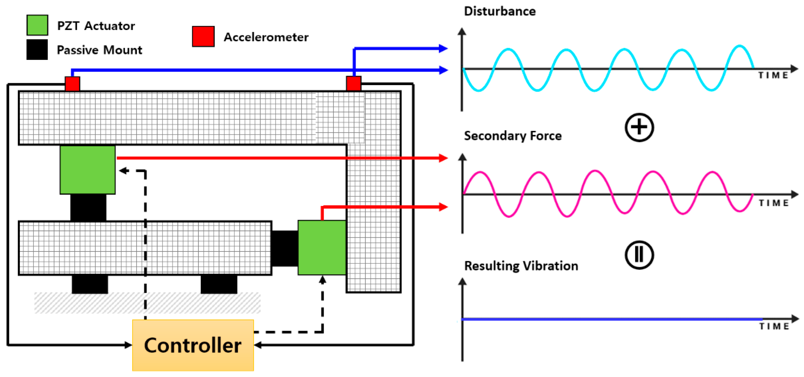
Consequently, smart-structure-based active engine mounting technology, which can improve ride comfort and NVH performance in a variable environment by modifying the mount dynamics to suit the low- or high-frequency range, has garnered significant interest as a key technology in automobile development. Figure 2 shows a conceptual explanation of the active vibration control system in automotive mounts. Its principle (when simply explained) is that when a sine wave disturbance is applied, as shown in the upper right picture, the secondary force from the actuator is generated and has the same frequency, same amplitude, but a 180-degree different phase with the disturbance. When these two signals are added, the resulting vibration can (theoretically) be completely eliminated at the end.

1.2. Literature Search

An engine mount functions as an integral component of a vehicle, providing support to the powertrain and preventing the transmission of vibrations from the powertrain to the vehicle chassis. Rubber, which is viscoelastic by nature, is conventionally employed; however, its application is restricted to low-frequency insulation, as it lacks the capability to regulate vibrations in the high-frequency range. To commercialize electric vehicles, the automotive industry has recently made significant investments; consequently, numerous studies are being conducted to determine how to regulate the more complex external force produced by gearboxes and motors compared to those produced by internal combustion engines. The principles and limitations of passive, semi-active, and active mounts have been outlined by Yu et al. [1]. Passive mounts, such as manual hydraulic mounts and elastic mounts, effectively regulate vibration in the low-frequency range but are incapable of doing so in the high-frequency range. Semi-active mounts commonly employ magneto-rheological (MR and electro-rheological (ER) fluids, which exhibit superior vibration control capabilities in the low-frequency range compared to passive mounts but remain ineffective in the high-frequency range. Active elastic and active hydraulic mounts, which combine an actuator with an existing passive mount, are representative of active mounts. Vibrations can be regulated in both high- and low-frequency ranges by modulating the dynamic rigidity of the actuator corresponding to each frequency band. A nonlinear and experimental model of a motor mount with a solenoid actuator was created by Hosseini et al. [2]. By connecting a viscous damper and an actuator in series, Kraus et al. [3] demonstrated how to create an engine mount; their model decreased vibration and noise. Chae et al. [4] installed an MR damper on an ambulance bed stage to reduce the vibrations. Yang et al. [5] used an adaptive multi-notch filtering technique to isolate the vibrations from four hydraulic actuators. Jeon et al. [6] presented a novel controlled engine-mounting system utilizing a piezo stack actuator for the RH mount and a magneto-rheological fluid actuator for the roll mount. A magnetostrictive actuator was used in tests by Jiang et al. [7] to regulate vibration actively. Fakhari et al. [8] established isolation by applying a robust reference adaptive control model to an electromagnetic engine mount through simulations and experimentation. Elahinia et al. [9] introduced a semi-active actuator using magneto-rheological and electro-rheological fluids to demonstrate its effectiveness in isolating vibrations and shocks. Wu et al. [10] used a magnetic spring with high static–low dynamic stiffness (MS-NS) properties to create a vibration insulator. Truong [11] constructed a mathematical model and simulated the hydraulic engine. Kamada et al. [12] showed that combining a column and piezoelectric actuator for active vibration control may effectively isolate the vibration of a structure. Loukil et al. [13] presented a technique for harnessing the power of a piezo actuator through energy harvesting that exhibited successful isolation performance. Sui et al. [14] used a PZT to create a vehicle engine mount with fast reaction characteristics, and they used a simulation to demonstrate the vibration reduction performance.
Choi et al. compared the vibration-reduction efficacy of a shear-mode-type ER fluid engine mount using a sliding-mode controller (SMC) [15]. Research has demonstrated that the vibration response of an SMC operating with a variable electric field for the input current is diminished compared to the case of applying a constant electric field. Using an MR fluid, Sarkar et al. proposed a method for designing an optimal engine mount. Vibration is diminished across all frequency ranges through magnetic field control to regulate the dynamic stiffness of the MR fluid and obstruct its passage [16]. However, fluid discharge is a significant issue, and fluid is extremely difficult to control when utilized as an engine mount. Chang et al. supplemented the dynamic vibration absorber (DVA) method with the QZS (Quasi-Zero-Stiffness) method to regulate the anti-resonance produced at an extremely low frequency (2.3 Hz), which DVAs were incapable of controlling [17]. Through an active mount that integrates a rubber mount in series with a PZT (piezoelectric) stack actuator, Liette et al. [18] highlighted the efficacy of a hybrid vehicle’s power electric frequency band in reducing vibration and noise. Furthermore, Hong and Kim [19] conducted an analytical investigation on a mounting system that included a PZT stack actuator and rubber mount on a vehicle model with a plate structure and then also utilized one active mount and two rubber mounts; their findings verified the suitability of the system. In addition, Hong and Kim [20] developed a quantification technique to identify the best inputs for active structural routes analytically. The derived inputs must be adjusted through experimentation; however, they perform well numerically.
Qiu et al. validated the effectiveness of vibration reduction by varying the position of a PZT stack actuator in a plate structure model. Based on this information, they developed criteria to guide the placement of an active mount to mitigate vibrations [21] further. This approach can potentially be an optimal solution for addressing the fluid leakage issue and the uncontrollability problem in the high-frequency region of the current mounting system. In addition, it can leverage the rapid response and low power consumption benefits of PZT. When implementing active engine mounts (AEMs), it is crucial to consider the controller. Theoretical and experimental analyses of secondary path changes in AEMs were conducted by Hausberg et al., who also utilized the Fx-LMS algorithm, an adaptive filter, to forecast the dynamic properties of AEMs [22]. Bartel et al. [23] introduced a novel engine mount design incorporating dynamic force resistance. As demonstrated by the results, the proposed engine mount could isolate vibrations. Numerous research initiatives are currently underway to implement active control via skyhook attenuation. In their study, Li and Goodall [24] examined various control methodologies implemented in the active suspension systems of railway vehicles and utilized skyhook damping control. The absolute velocity signal was filtered using Kalman-filter-based nonlinear techniques. An energy-adaptive skyhook gain was incorporated into a novel, zero-energy active suspension system proposed by Singal and Rajamani [25]. This methodology demonstrated that the system functions as an active system across a wide frequency spectrum and a passive system across all frequencies. Emura et al. [26] devised a semi-active suspension system featuring skyhook dampening to enable the active regulation of the damping coefficient and configuration of the system. Chai et al. investigated the active control application of composite lattice sandwich plates with piezoelectric actuators and sensors. The response of the plates was determined using nonlinear equations, and velocity feedback and H-infinity controllers were implemented [27].

1.3. Research Purpose

Through studying instances of interest, scientists are developing several types of smart materials for vibration insulation of the car body caused by the engine. The vibrations were isolated using engine-mounting solutions based on smart structures. Because of the nature of ER and MR fluids and the possibility of fluid leakage, semi-active mounting systems struggle to regulate vibrations across a broad frequency range. An active mounting method that combines a piezoelectric actuator with rubber, a viscoelastic material, is presented to address this issue. Researchers have suggested using an adaptive filter as the actuator input signal and monitoring the system response signal to reduce vibration. Furthermore, a technique for altering the structure when a single frequency is stimulated or a narrowband vibration reduction is desired is not appropriate for an electric car that is impacted by complicated signals produced by the gearbox, transmission, and motor.
As a result, we considered vertical and horizontal vehicle engine mount combinations when designing the source–path–receiver structure in this study. We also measured the vibration reduction achieved by utilizing the PZT stack actuator and active mount in conjunction with rubber. The actuator used in this concept has a force acting along the direction of the path and the external force has the most direct effect on the vertical mount. In real situations, when excessive load is applied, there is a high probability that the vertical mount will have problems first. Thus, a situation in which the vertical actuator does not operate is assumed. A thorough approach for examining mounting structure vibrational behavior is suggested. A structure that was inspired by an automotive mount is examined and its interactions between vertical and lateral vibration are observed. Moreover, the effectiveness of vibration attenuation is assessed and contrasted with respect to the particular positions used to measure actuator input. Finally, the proposed structure is subjected to multi-spectral excitations in order to examine its vibration reduction capabilities for somewhat complex vibration signals.
This article is organized as follows: A two-dimensional, six-degrees-of-freedom model is presented in Section 2, with integrated active mounts in the vertical and horizontal directions. A scenario is considered in which the vertical active mount fails and only the horizontal active mount remains operational. The attenuation performance is compared by analytically calculating the input value for each path with a single sinusoid excitation in Section 3.1. Additionally, the normalized LMS (NLMS) algorithm is used for the secondary channel (secondary force from the actuator) when complex signals such as amplitude-modulated (AM) and frequency-modulated (FM) signals are stimulated in Section 3.2. The findings of this study and potential avenues for future research are outlined in Section 4 as conclusion.

2. Horizontal Active Mounting System for Vibration Reduction

2.1. Six Degrees of Freedom Modeling

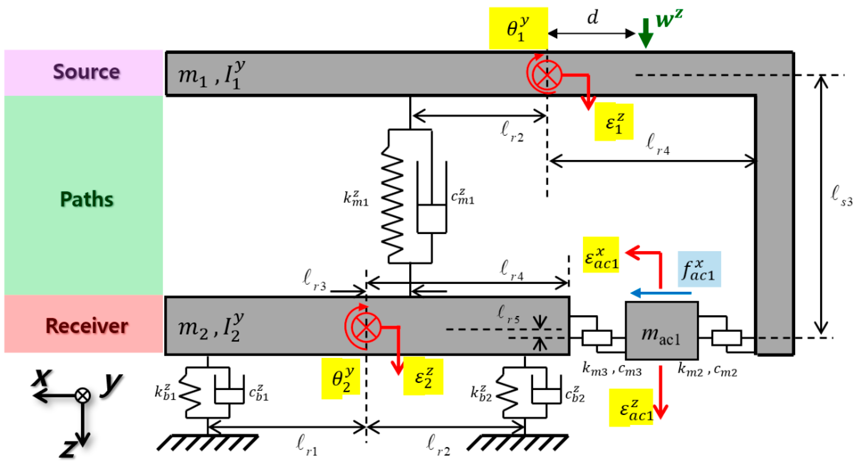
The modeling was performed assuming that the horizontal active mount would remain operational if the vertical active mount failed. Figure 3 shows the vehicle subframe construction, AEM, and powertrain. The vibration source was identified as the engine, the vibration routes were the rubber-coupled active mount and the piezo stack actuator, and the vibration recipient was the subframe. The source was built as a curved two-dimensional structure, whereas the receiver was created as a two-dimensional beam structure because the engine mounted on the real vehicle was fixed horizontally to the engine and subframe.
The mass of the source is represented by m 1 , the receiver mass by m 2 , the actuator mass in the horizontal direction by m a c 1 , the source moment of inertia in the y direction by I 1 y , and the receiver moment of inertia in the y direction by I 2 y . The distances between each route and the center of gravity of the source and receiver are denoted by variables l s i and l r i , respectively, whereas the distance between the source and position of the exciting force application is denoted by variable d . The actual stiffness and damping are represented as k m i z , k m i x , and k b i z and c m i z , c m i x , and c b i z when the complex stiffness values are transformed into the Kelvin–Voigt formula. In this study, a six-degrees-of-freedom model was proposed to explain the horizontal translational motion, rotating motion along the y-axis, vertical translational motion of the horizontally linked active mount, and vertical translational motion of the source and receiver. The source’s vertical displacement ε 1 z and the corresponding angle of rotation θ 1 y , the receiver’s vertical displacement ε 2 z and the corresponding angle of rotation θ 2 y , the vertical displacement of the horizontal active mount ε a c 1 z , and the horizontal displacement ε a c 1 x make up the displacement vector.
Equation (1) shows the equation of motion obtained from the previous model using Newton’s second law, where W z is the excitation force and f a c 1 x is the control force of the horizontal active mount.
M q ¨ + C q ˙ + K q = W + F
Values are assigned to the following components of Equation (1): q denotes the displacement vector, M is the mass matrix, C is the damping matrix, K is the rigidity matrix, W is the excitation force vector, and F is the control force vector pertinent to the active mount. Equations (2)–(7) encompass expressions for the mass matrix, stiffness matrix, damping matrix, displacement vector, excitation force vector, and control force vector:
M = d i a g m 1 m 2 m a c 1 m a c 1 I 1 y I 2 y ,
K = k m 1 z + k m 2 z k m 1 z k m 2 z k m 2 z x k m 1 z k m 1 z + k m 3 z + k b 1 z + k b 2 z k m 3 z k m 3 z x k m 2 z k m 3 z k m 2 z + k m 3 z k m 2 z x k m 3 z x k m 2 z x k m 3 z x k m 2 z x k m 3 z x k m 2 x + k m 3 x k m 2 z l s 2 k m 2 z x l s 3 k m 1 z l s 1 k m 1 z l s 1 k m 2 z l s 2 + k m 2 z x l s 3 k m 2 z x l s 2 k m 2 x l s 3 k m 1 z l r 3 k m 1 z l r 3 + k m 3 z l r 4 k b 1 z l r 1 + k b 2 z l r 2 k m 3 z x l r 5 k m 3 z l r 4 + k m 3 z x l r 5 k m 3 z x l r 4 k m 3 x l r 5
k m 2 z l s 2 k m 1 z l s 1 k m 2 z x l s 3 k m 1 z l r 3 k m 1 z l s 1 k m 1 z l r 3 + k m 3 z l r 4 k b 1 z l r 1 + k b 2 z l r 2 k m 3 z x l r 5 k m 2 z l s 2 + k m 2 z x l s 3 k m 3 z l r 4 + k m 3 z x l r 5 k m 2 x l s 3 + k m 2 z x l s 2 k m 3 x l r 5 + k m 3 z x l r 4 k m 1 z l s 1 2 + k m 2 z l s 2 2 + k m 2 x l s 3 2 2 k m 2 z x l s 2 l s 3 k m 1 z l s 1 l r 3 k m 1 z l s 1 l r 3 k m 1 z l r 3 2 + k m 3 z l r 4 2 + k m 3 x l r 5 2 + k b 1 z l r 1 2 + k b 2 z l r 2 2 2 k m 3 z x l r 4 l r 5 ,
C = c m 1 z + c m 2 z c m 1 z c m 2 z c m 2 z x c m 1 z c m 1 z + c m 3 z + c b 1 z + c b 2 z c m 3 z c m 3 z x c m 2 z c m 3 z c m 2 z + c m 3 z c m 2 z x c m 3 z x c m 2 z x c m 3 z x c m 2 z x c m 3 z x c m 2 x + c m 3 x c m 2 z l s 2 c m 2 z x l s 3 c m 1 z l s 1 c m 1 z l s 1 c m 2 z l s 2 + c m 2 z x l s 3 c m 2 z x l s 2 c m 2 x l s 3 c m 1 z l r 3 c m 1 z l r 3 + c m 3 z l r 4 c b 1 z l r 1 + c b 2 z l r 2 c m 3 z x l r 5 c m 3 z l r 4 + c m 3 z x l r 5 c m 3 z x l r 4 c m 3 x l r 5
c m 2 z l s 2 c m 1 z l s 1 c m 2 z x l s 3 c m 1 z l r 3 c m 1 z l s 1 c m 1 z l r 3 + c m 3 z l r 4 c b 1 z l r 1 + c b 2 z l r 2 c m 3 z x l r 5 c m 2 z l s 2 + c m 2 z x l s 3 c m 3 z l r 4 + c m 3 z x l r 5 c m 2 x l s 3 + c m 2 z x l s 2 c m 3 x l r 5 + c m 3 z x l r 4 c m 1 z l s 1 2 + c m 2 z l s 2 2 + c m 2 x l s 3 2 2 c m 2 z x l s 2 l s 3 c m 1 z l s 1 l r 3 c m 1 z l s 1 l r 3 c m 1 z l r 3 2 + c m 3 z l r 4 2 + c m 3 x l r 5 2 + c b 1 z l r 1 2 + c b 2 z l r 2 2 2 c m 3 z x l r 4 l r 5 ,
q = ε 1 z ε 2 z ε a c 1 z ε a c 1 x θ 1 y θ 2 y T ,
W = W z 0 0 0 W z d 0 T ,
F = 0 0 0 f a c 1 x 0 0 T .
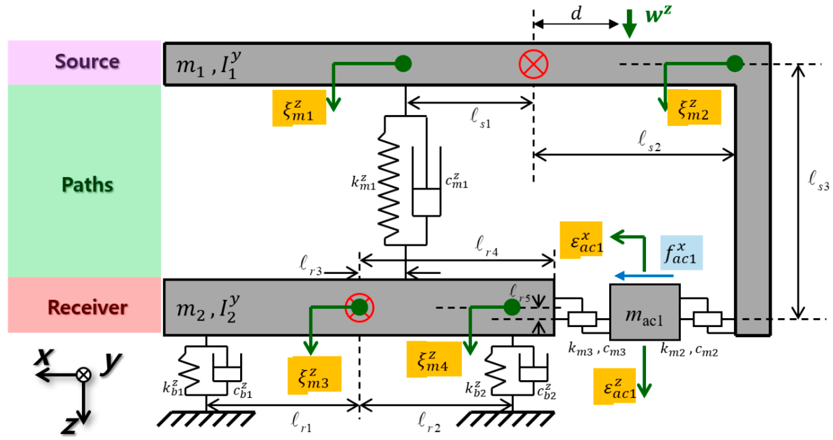
To assess the importance of the vibration-reduction performance resulting from the influence of the active mount, the model constructed using the center-of-gravity coordinates was transformed into mount coordinates to analyze the displacement of the position adjacent to the mount, as illustrated in Figure 4.
The source’s vertical displacement next to the vertical mount in Figure 4 is represented by ξ m 1 z , the source’s vertical displacement next to the horizontal mount by ξ m 2 z , the receiver’s vertical displacement next to the vertical mount by ξ m 3 z , and the receiver’s vertical displacement next to the horizontal mount by ξ m 4 z . The transformation matrix of the six-degrees-of-freedom model is given in Equation (9) by assigning each location to the internal and external dividing point equations, as shown in Equation (8).
ε 1 z = ξ m 1 z l s 2 + ξ m 2 z l s 1 l s 1 + l s 2 = l s 2 l s 1 + l s 2 ξ m 1 z + l s 1 l s 1 + l s 2 ξ m 2 z
Π = l s 2 l s 1 + l s 2 l s 1 l s 1 + l s 2 0 0 0 0 0 0 l r 4 l r 3 + l r 4 l r 3 l r 3 + l r 4 0 0 1 0 0 1 l s 1 + l s 2 1 l s 1 + l s 2 0 0 0 0 0 0 1 l r 3 + l r 4 1 l r 3 + l r 4
The displacement vector of the mount coordinates can be represented by Equation (10), utilizing the transformation matrix of Equation (9). To convert the equation of motion to mount coordinates, the transformation matrix must be multiplied by the mass, damping, and stiffness matrices of the center of gravity coordinates, as shown in Equation (11).
q = ξ m 1 z ξ m 2 z ε a c 1 z ξ m 3 z ξ m 4 z T
M ¨ q ¨ + C q ˙ + K q = W + F
The effective confirmation of the vibration-reduction performance when only the vertical active mount is operating comes from the horizontal direction response trend derived from the equation of motion converted to mount coordinates, the dynamic relational expression in the following section, and Equation (11).

2.2. Horizontal Displacement Trend through Dynamic Relations

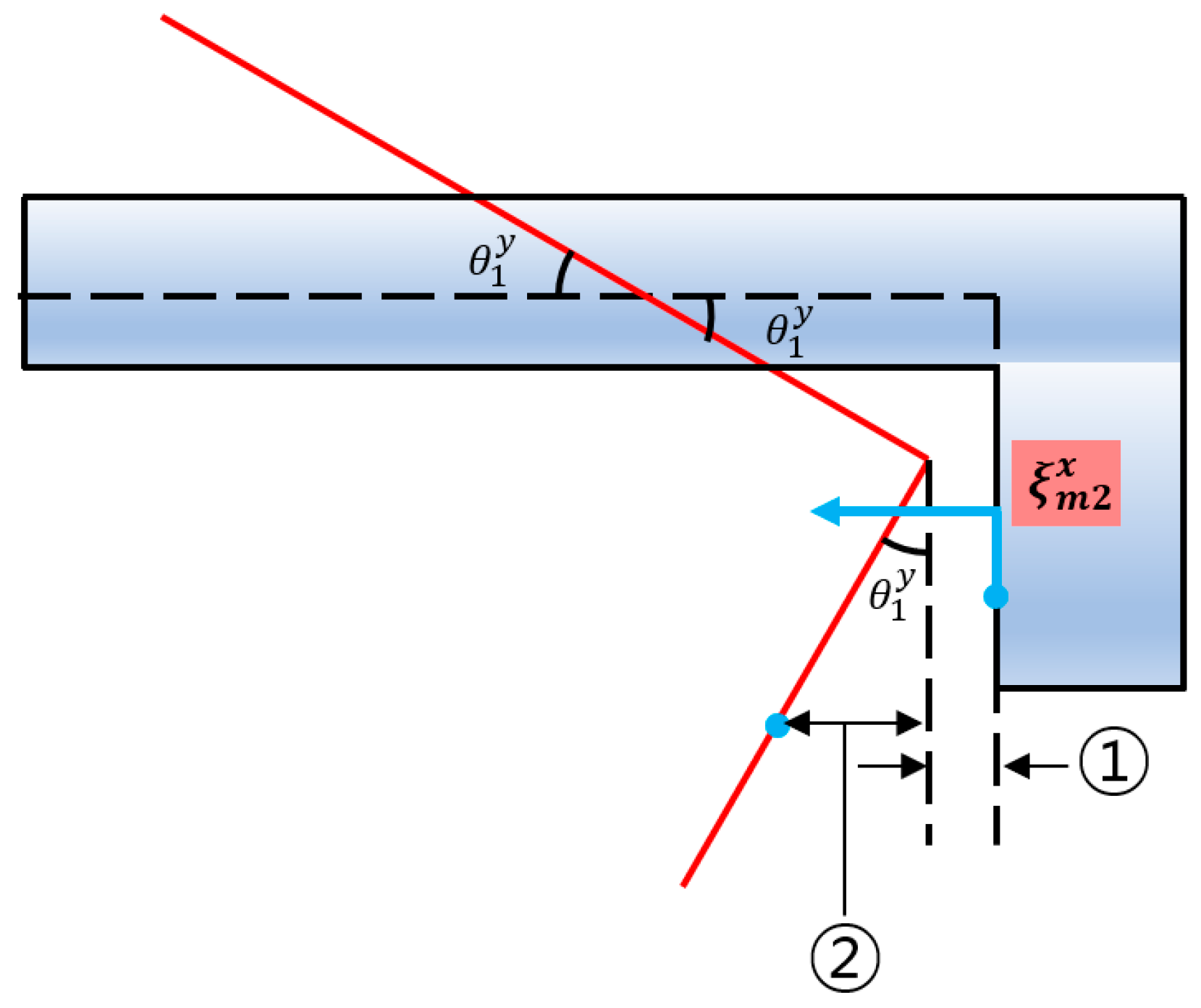
The proposed aggregated parameter model does not permit the determination of the horizontal response; however, it enables the determination of the vertical response at each position. This study utilized the dynamic relationship of the structure to compute the horizontal direction response trend for each position. Additionally, this study identified the position adjacent to the horizontal mount that substantially influences the displacement in the horizontal direction. Figure 5 illustrates the dynamic mobility of the source structure.
In the above illustration, the source is shown in its equilibrium condition by the dotted line, whereas the source is shown to move due to an external force from the solid line. The displacement of the source near the horizontal mount is equal to the sum of and ②, where comes from the property of an isosceles triangle and the trigonometric formula of Equation (12) and ② comes from the ratio of similitude, as specified in Equation (13).
= ξ m 2 z t a n θ 1 y 2
: ξ m 2 z = l s 3 s i n θ 1 y : l s 2 s i n θ 1 y
Based on Equations (12) and (13), Equation (14) defines the horizontal displacement trend of the source adjacent to the horizontal mount:
ξ m 2 x = t a n θ 1 y 2 + l s 2 l s 3 ξ m 2 z .
Equation (14) can be linearized to yield Equation (15).
ξ m 2 x = θ 1 y 2 + l s 2 l s 3 ξ m 2 z
As demonstrated by the preceding equation, the horizontal displacement of the source is affected by the geometry of the structure, the source rotation angle, and the vertical displacement. Because of the difficulty in altering the structure of the source, its horizontal displacement is determined by its vertical displacement. The dynamic movement of the receiver structure is illustrated in Figure 6.
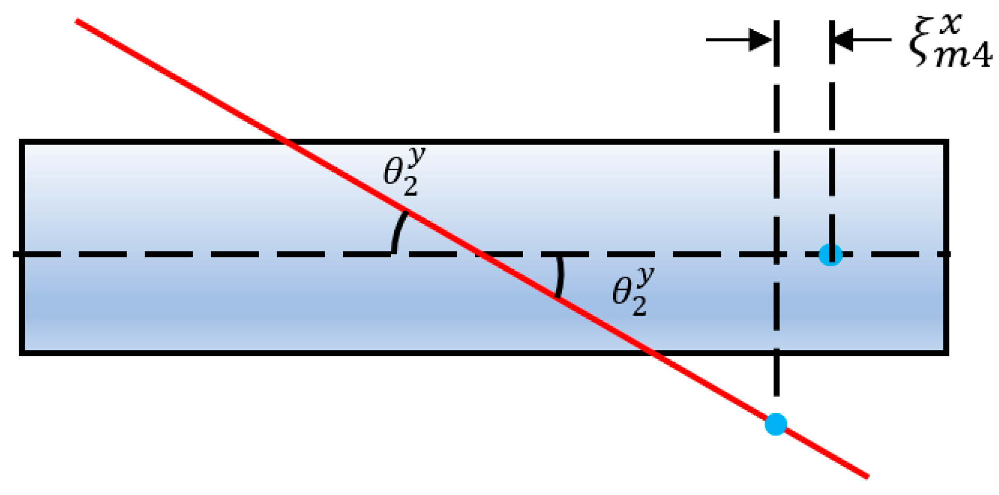
The dashed line in Figure 6 represents the equilibrium state of the receiver, and the solid line represents the receiver’s response to an external stimulus. The receiver displacement adjacent to the horizontal mount is defined as ξ m 4 x , which is equal to when deriving the horizontal displacement of the source using the characteristics of an isosceles triangle and the formula for a trigonometric function.
ξ m 4 x = ξ m 4 z t a n θ 2 y 2
Equation (16) can be linearized to yield Equation (17).
ξ m 4 x = θ 2 y 2 ξ m 4 z
This equation demonstrates that its rotation angle and vertical displacement influence the horizontal displacement of the receiver. Consequently, it can be controlled through horizontal receiver displacement. Therefore, the vertical and horizontal responses of the 7-DOF model were examined.

2.3. Secondary Pathway Input Quantification

The response produced when a harmonic force is activated depends significantly on both the amplitude and phase values. The excitation and control forces can be expressed in a complex number form using Euler’s law as Equations (18) and (19), respectively, because the harmonic force can be expressed in a complex number form using Euler’s law.
W z t = W z e i ω t
f a c 1 z t = f a c 1 z e i ( ω t + ϕ a c 1 )
The excitation force amplitude in the equation above is denoted by W z , the excitation frequency by the horizontal direction control force amplitude by f a c 1 x , and the horizontal direction control force phase by ϕ a c 1 . Applying the excitation and control forces to the mount coordinate model yields a response at each location. Equation (20) displays each position response.
ξ t = ξ m i z t
The response that is influenced by the excitation force and the control force input through the secondary channel is ξ m i z t , which is the vertical displacement of the i-position of the mount coordinates. The compliance matrix, the inverse of the dynamic stiffness matrix, was used to determine the matrix. Equations (21) and (22) were used to express the dynamic stiffness and compliance matrices, respectively, based on the mount coordinates.
κ = ω 2 M + i ω C + K
H = κ 1 = H 11 H 12 H 13 H 14 H 15 H 21 H 22 H 23 H 24 H 25 H 31 H 32 H 33 H 34 H 35 H 41 H 42 H 43 H 44 H 45 H 51 H 52 H 53 H 54 H 55
The displacement at each position of the mount coordinates is derived from the compliance matrix using Equation (23).
q = H W + H F
As shown in Equation (23), the response can be expressed using the compliance matrix, excitation force, and control force. This shows that the amplitude of the excitation force, amplitude of the control force, and phase can be used to express the movement of each location. The displacement of each location is established using Equation (24).
ξ j t = Ξ m j z e i β m j + Ξ m j . a c 1 z e i ϕ a c 1 + β m j . a c 1 e i ω t
The displacement responses at position j have an amplitude Ξ m j z owing to the excitation force, a phase β m j due to the excitation force, an amplitude Ξ m j . a c 1 x due to the horizontal mount control force, and a phase β m j . a c 1 due to the horizontal mount control force. Using the compliance matrix, Equations (25)–(28) represent the amplitude and phase, respectively.
Ξ m j z = H j 1 + H j 4 d W z
Ξ m j . a c 1 z = H j 3 f a c 1 z
β m j = H j 1 + H j 4 d
β m j . a c 1 = H j 3
Therefore, all but two unknowns of the amplitude and phase of the horizontal mount control force are known in Equation (24), which represents the displacement. We assume a control force phase that makes the phase values equal, as indicated in Equation (29), to compute the horizontal mount control force that causes zero displacement.
β m j = β m j . a c 1 + a c 1
The phase that the vertical mount should have in accordance with Equation (29), as shown in Equation (30), is as follows:
a c 1 = β m j β m j . a c 1 .
Equation (30) is substituted into Equation (24) to obtain the following definition:
ξ j t = Ξ m j z + Ξ m j . a c 1 z e i ω t + β m j .
Equation (24) allows the displacement at position j to be equal to zero by setting the amplitude component to 0. As only one unknown exists, this displacement can be calculated using only one equation. The horizontal mount amplitude that causes the displacement of the jth position to zero is determined using Equation (32) by substituting Equations (25) and (26) for the amplitude component of Equation (31).
f a c 1 z = W z H j 1 + H j 4 d H j 3
Therefore, the control force containing the phase value of Equation (30) and amplitude value of Equation (32) must be supplied to the secondary path to regulate the displacement of the j-th position to zero. There are four different strategies for achieving zero displacement of the location next to the mount in the six-degrees-of-freedom model. These include the (1) source displacement next to the vertical mount, (2) receiver displacement next to the vertical mount, (3) source displacement next to the horizontal mount, and (4) receiver displacement next to the horizontal mount.

3. Simulation

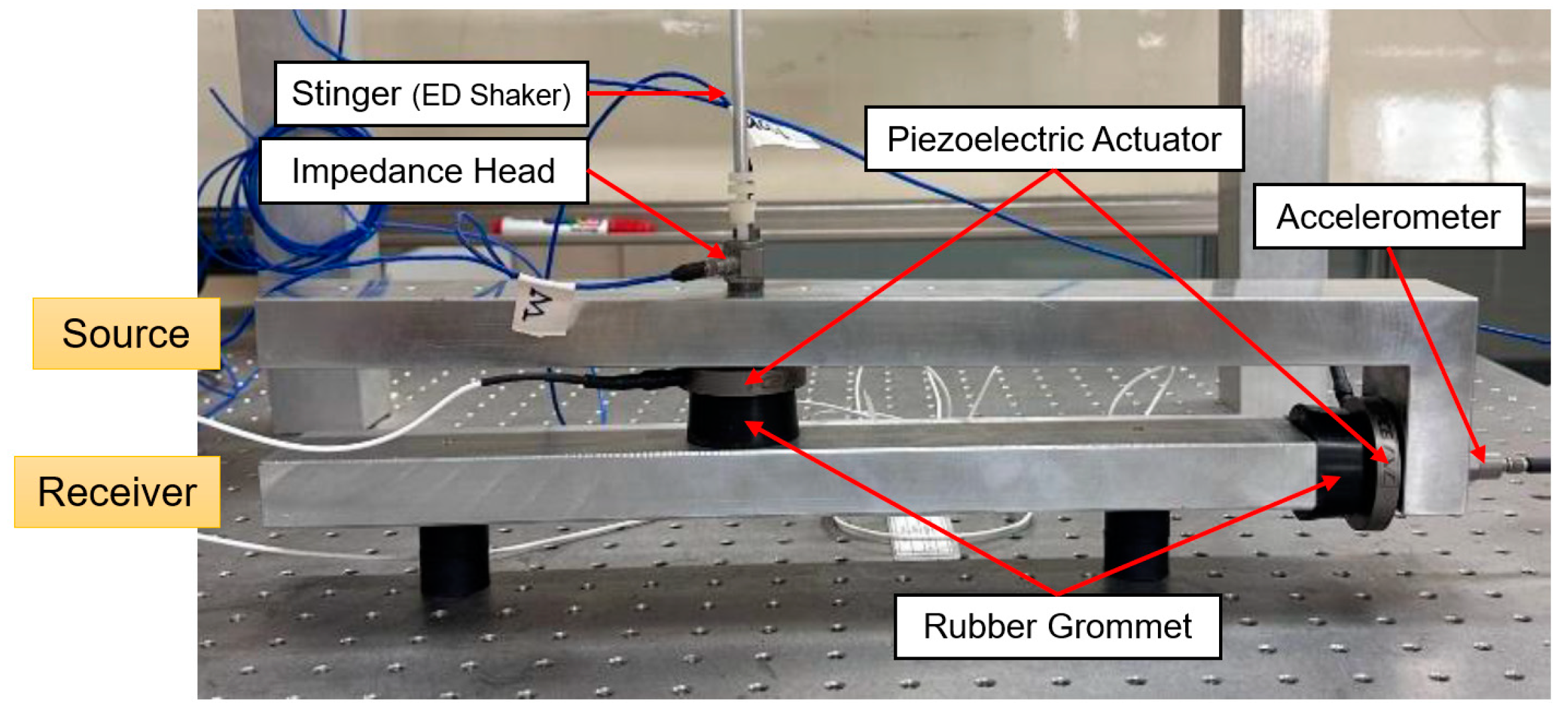
A simulation was performed to confirm the functionality of the model before experimenting to validate the previously generated formulae using a laboratory setup with a structure with two mounts. The simulation parameters are listed in Table 1, which were derived from the following experimental setup in Figure 7. In a subsequent study, this setup will be used to confirm the simulation results: The upper part is the source, which symbolizes the vehicle’s engine, while the lower part is the receiver, which symbolizes the subframe of the vehicle. Each active path consists of a piezoelectric stack actuator and a rubber grommet. The accelerometer signal was measured in real time using DS1104 (from dSPACE GmbH, Paderborn, Germany) and disturbance force was applied using an electrodynamic shaker; it was measured using the impedance head attached to the end of the stinger. Calculations were performed for masses and inertias. An accelerometer monitored the reaction of the stack mass when excited by a chirp voltage signal, which was used to evaluate stiffness and damping values. As a result, there was only one resonance peak, and the stiffness value was calculated using the half-power approach and the natural frequency formulation.
The secondary path input value substitution simulation was performed with vertical and horizontal active mounts positioned at the center of gravity of the source and receiver. The vibration reduction performance was verified by comparing the reaction when the excitation force was input alone with the response when the excitation force and estimated control input were applied. The response was confirmed using a linear time-invariant state–space approach. Using the mass-damping–spring equation of motion transformed to the mount coordinates of Equation (11), the state–space equation is defined as Equations (33)–(35).
x ˙ t = A x t + B u t
y t = C x t + D u ( t )
A = 0 5 × 5 I 5 × 5 M 1 K M 1 C   B = 0 5 × 5 M 1
C = I 2 × 2 0 2 × 1 0 2 × 2 0 2 × 5 0 2 × 2 0 2 × 1 I 2 × 2 0 2 × 5   D = 0
Matrices A, B, C, and D in Equation (35) represent the system state, input, output, and direct transfer term, respectively. The outcome of the simulation is expressed as the displacement of the position next to the mount by changing the state variable in line with Equation (37).
y t = ξ m 1 z t ξ m 2 z t ξ m 3 z t ξ m 4 z t T

3.1. Control via Quantified Input

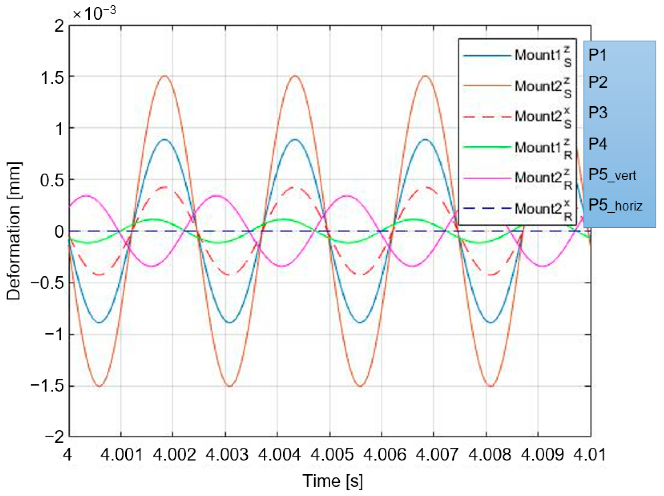
To mimic the calculated secondary route input of the 5-DOF model, the excitation frequency was set to 400 Hz, the excitation amplitude to a sinusoidal signal of 10 N, and the sampling frequency to 15 kHz. Figure 8 shows the displacement responses for the 6-DOF model when only the excitation force was used.
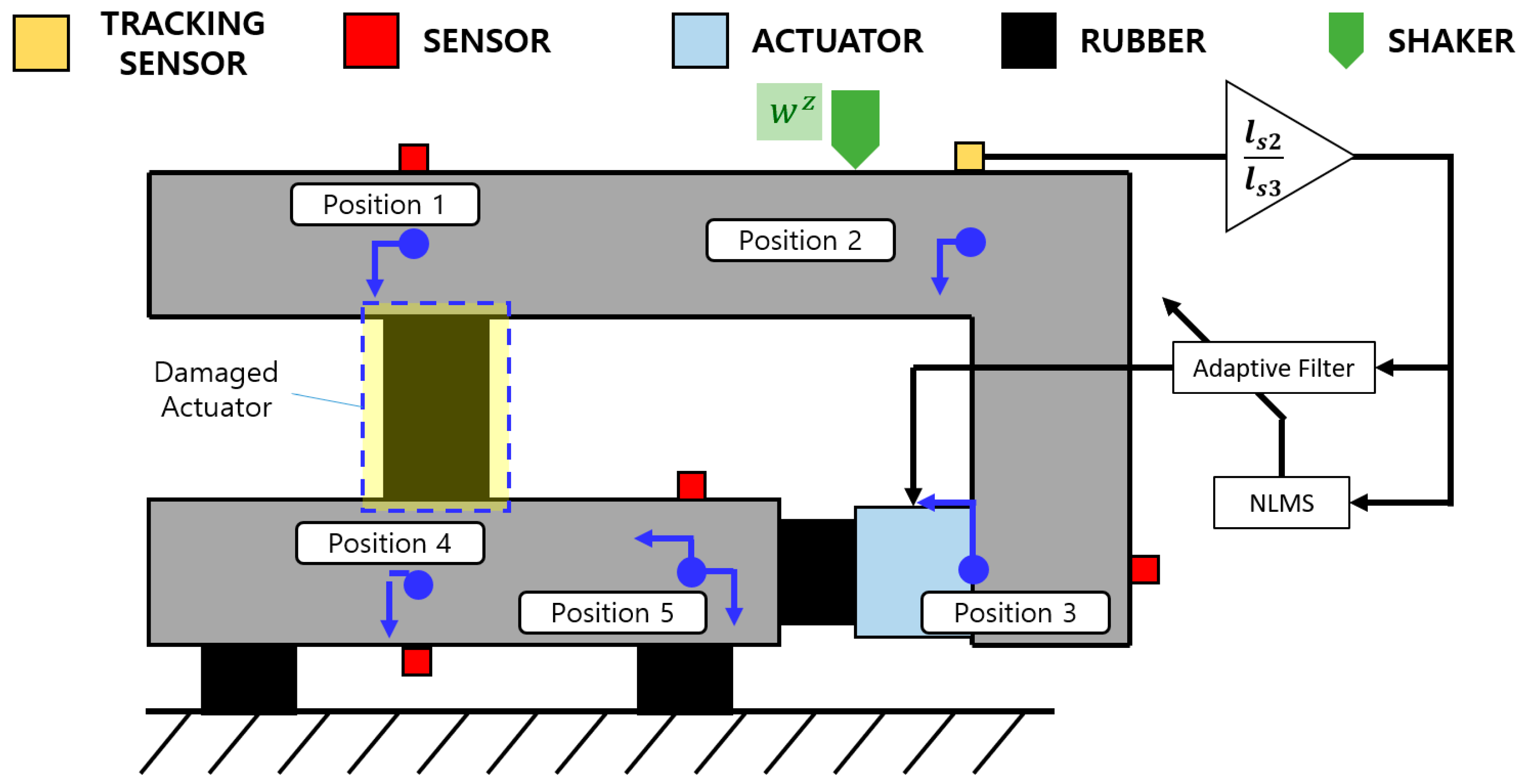
M o u n t i s z , in Figure 8, represents the vertical displacement of the i-th source position based on the left side of the mount coordinates, M o u n t 2 s x represents the horizontal displacement of the source adjacent to the horizontal mount, M o u n t i R z represents the vertical displacement of the i-th receiver position, and M o u n t 2 R x represents the horizontal displacement of the receiver adjacent to the horizontal mount. The source immediately impacted by the excitation force shakes significantly when a control force is not provided via the secondary channel, as shown in Figure 8. M o u n t 2 S z , which is distant from the center of gravity, is particularly vulnerable to vibrations. This problem was solved by substituting the secondary path input values determined using the four previously described approaches, which confirmed the vibration reduction performance. The steady-state response graph and root mean square of the steady-state response were used to compare the 6-DOF vibration-reduction effectiveness of each method. An example of the basic simulation scheme is shown in Figure 9.
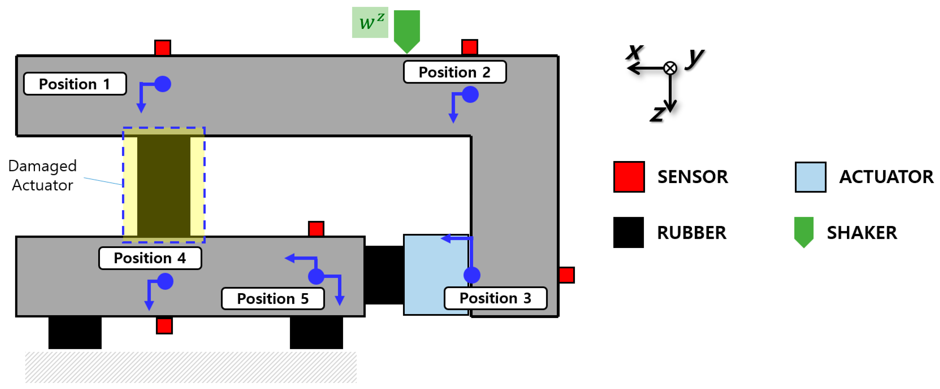
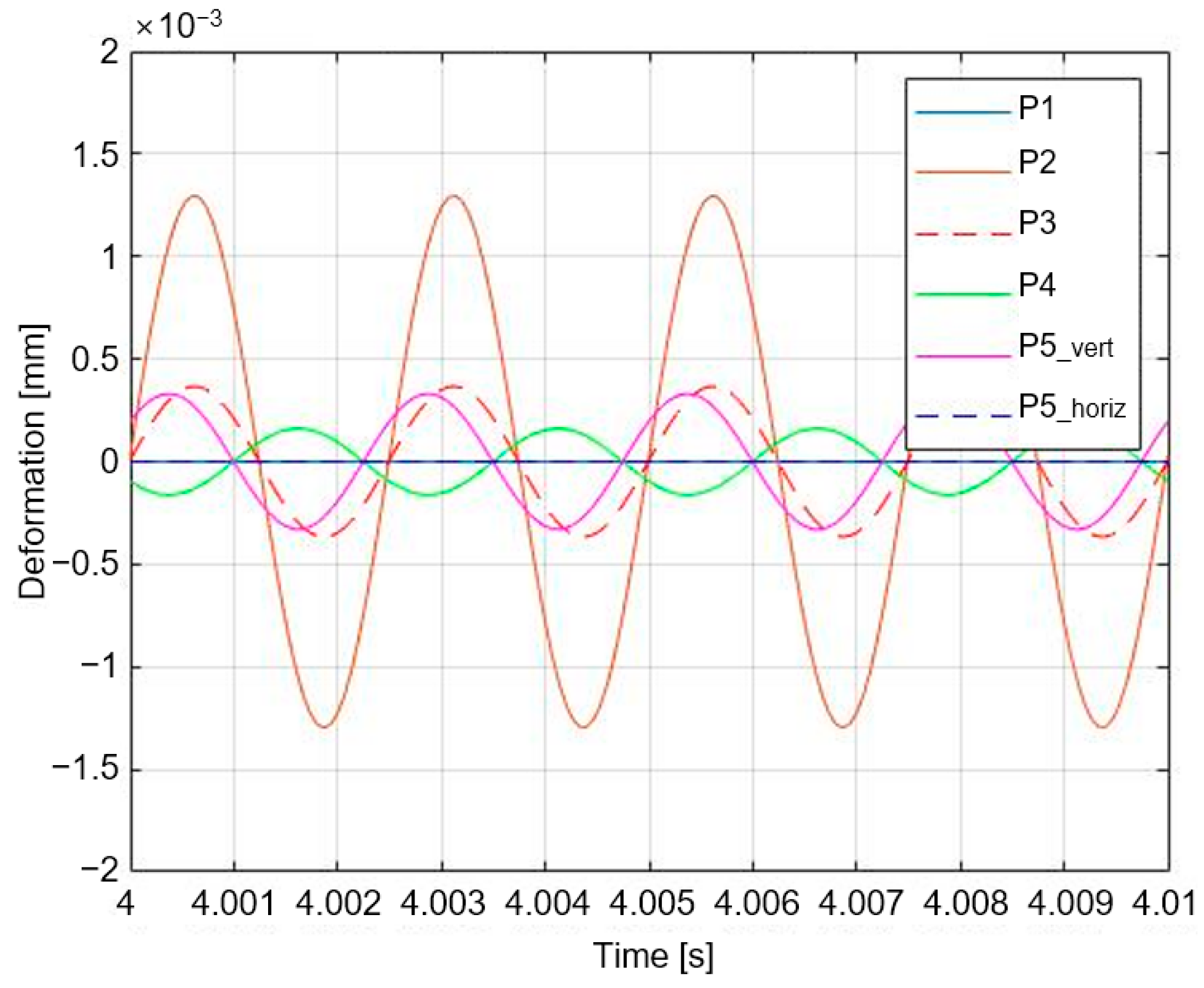
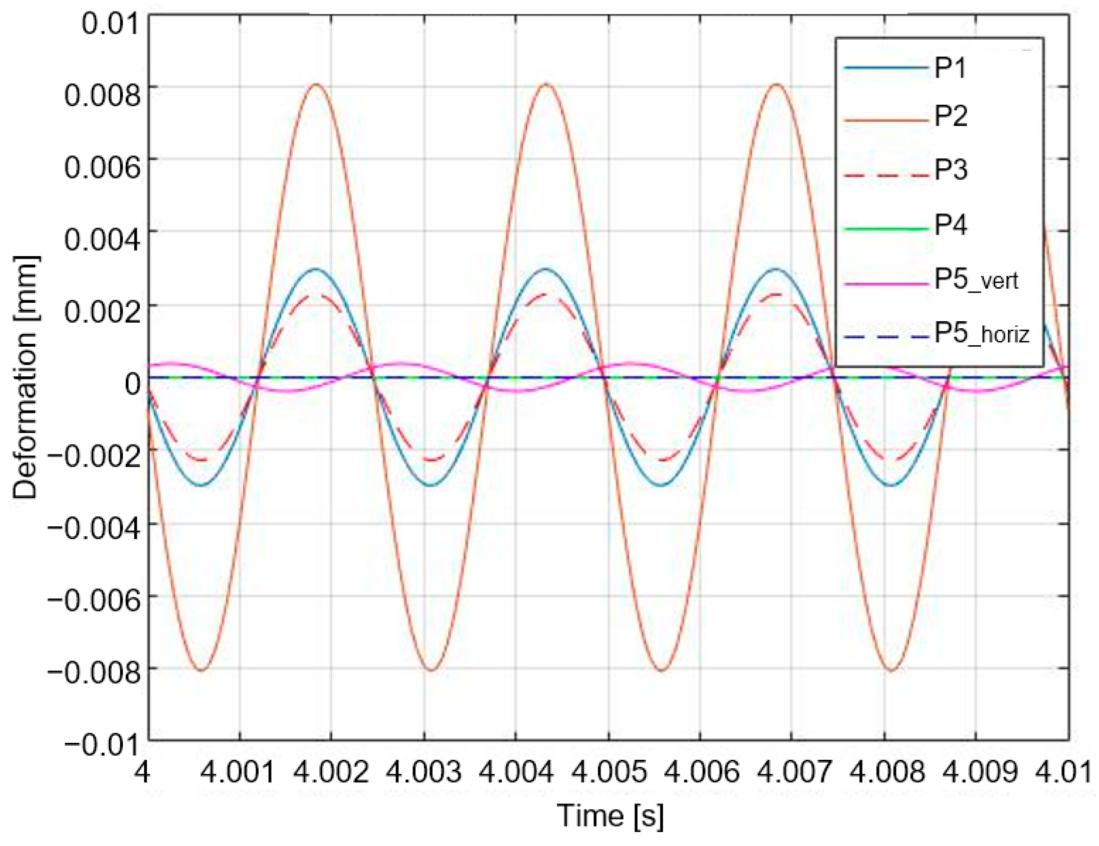
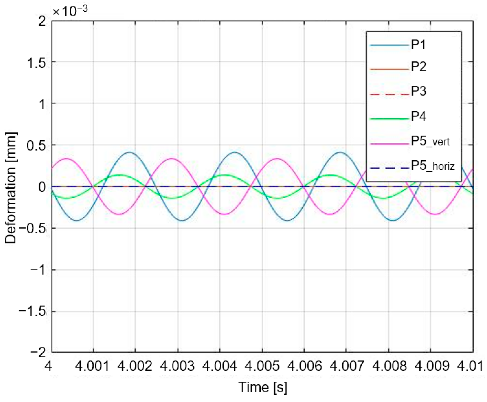
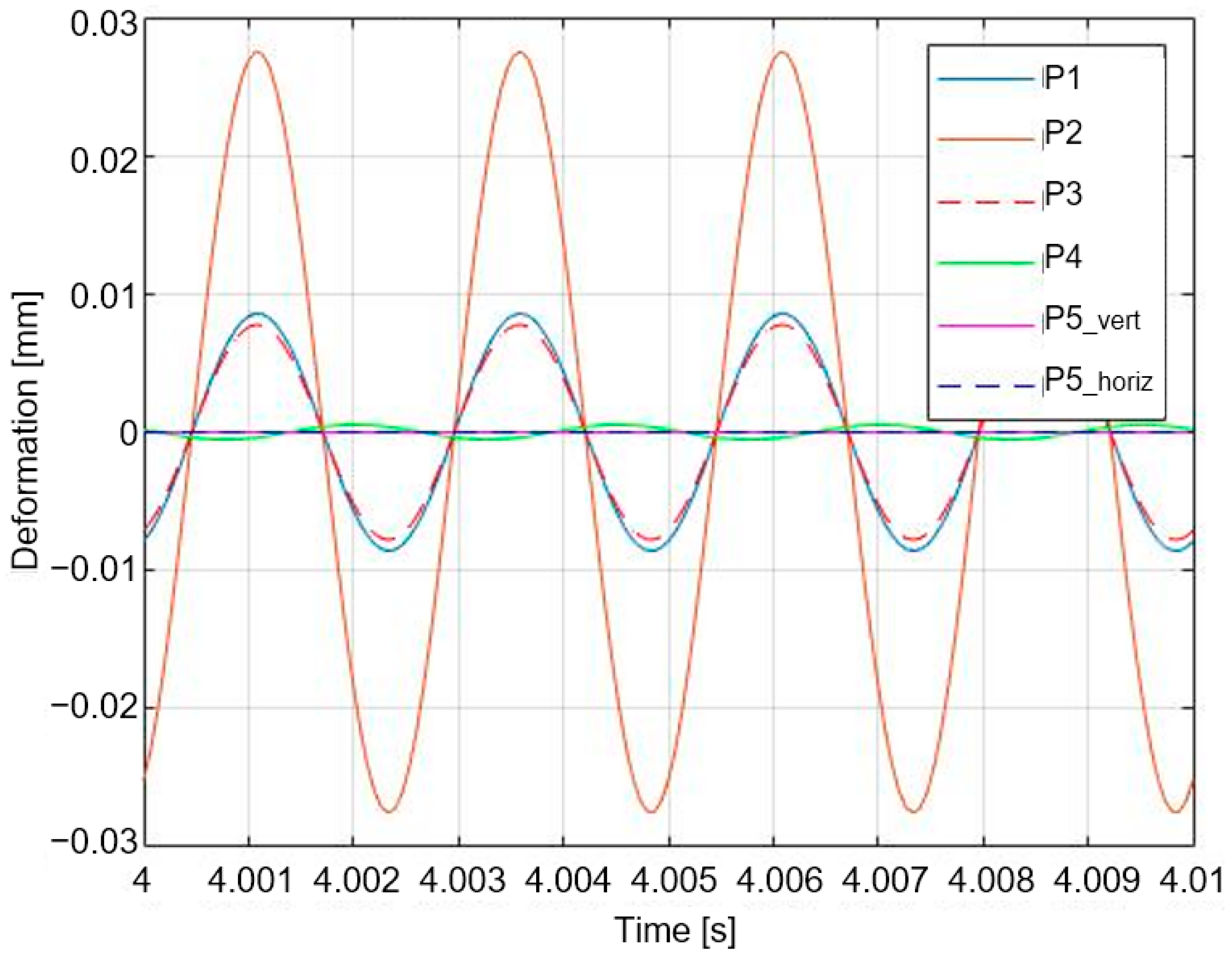
In Figure 9, position 1 represents the response M o u n t 1 S z (marked as P1), position 2 represents M o u n t 2 S z (marked as P2), position 3 represents M o u n t 2 S x (marked as P3), position 4 represents M o u n t 1 R z (marked as P4), and position 5 represents M o u n t 2 R z (marked as P5_vert) and M o u n t 2 R x (marked as P5_horiz). To this end, Case 1 zeroes out the vertical displacement at position 1; Case 2 zeroes out the vertical displacement at position 4; Case 3 zeroes out the vertical displacement at position 2; and Case 4 successfully cancels out the vertical displacement at position 5. The simulation was performed by replacing the secondary path input of the horizontal active mount, which aimed to achieve a vertical displacement of zero, with an alternative. First, the control results for Case 1, which aims to achieve a vertical displacement of ‘0’ for the source adjacent to the vertical mount, are illustrated in Figure 10’s steady-state response graph and compared in Table 2 between the RMS values before and after the implementation of the control.
In Case 1, the secondary path input was a sinusoidal signal with a frequency of 400 Hz and an amplitude of −27.8996 N. The vibration of M o u n t 1 S z was reduced by 100%, that of M o u n t 2 S z and M o u n t 2 S x by 14.04%, and that of M o u n t 2 R z by 23.92%, whereas the vibrations of M o u n t 1 R z and M o u n t 2 R x were amplified by 43.34% and 4.22%, respectively. The method in Case 1 effectively dampens engine-generated vibrations but exacerbates subframe-generated vibrations.
Figure 11 and Table 3 illustrate the control results for Case 2 (the target vertical displacement of the receiver adjacent to the vertical mount is equal to zero).
In Case 2, the calculated input for the secondary path was a 400 Hz sine wave with an amplitude of −65.331 N. Except for the targeted vibration at M o u n t 1 R z , the remaining locations experienced an increase in vibration. Case 2 control requires a control force greater than six times the excitation force because the second path is calculated with the displacement at a location distant from the active mount.
Figure 12 and Table 4 illustrate the control results for Case 3 (target the vertical displacement of the source adjacent to the horizontal mount to ‘0’).
In Case 3, the calculated input for the secondary path was a 400 Hz sine wave with an amplitude of −15.0122 N. The vibration of M o u n t 1 S z was mitigated by 53.75% and 100% in the targeted M o u n t 2 S z , 100% in M o u n t 2 S x , and 1.85% in M o u n t 2 R z , whereas the vibration tended to worsen by 22.97% for M o u n t 1 R z and 2.46% for M o u n t 2 R x . This demonstrates that the engine vibration was well controlled in Case 3, whereas the subframe vibration could not be controlled.
The control results for Case 4 are depicted in Figure 13 and Table 5 (the intended vertical displacement of the receiver adjacent to the horizontal mount is ‘0’).
In Case 4, the secondary path input was a sinusoidal signal with a frequency of 400 Hz and an amplitude of −278.9964 N. Although the targeted M o u n t 2 R z and M o u n t 2 R x demonstrated a tendency for 100% vibration reduction, the vibration tended to increase at all other positions. This is because the force required for control in Case 4 is unreasonably greater than the amplitude of the exciting force; therefore, only the displacement at the target position is controlled, and the control force at other positions exacerbates the vibration. Therefore, the control in Case 4 is ineffective and exacerbates the vibration. A comparison of the results for each case reveals that the 6-DOF model exhibits appropriate control power and control results only at the targeted position with generally negative effects on the other positions.

3.2. Control through NLMS Algorithm

When employing the calculated secondary path input for control, the control force must be recalculated in response to modifications in the external environment or the excitation force. To address this concern, we employed an adaptive filter that adjusts the filter coefficients according to the environmental conditions. LMS algorithms, which are representative adaptive filter algorithms, can regulate vibrations. The LMS algorithm is a straightforward and dependable method implemented extensively for vibration and noise reduction. However, the initial values have a significant impact on the convergence characteristics of the filter coefficients, resulting in a comparatively slow convergence rate.
The LMS algorithm is a recursive adaptive filtering system algorithm. The variables y k , d k , and k represent the filter output, the original signal (system output), and the discrete time, respectively. The relationship between an error signal e k , a reference signal u k , and a filter coefficient vector w k is defined as follows:
w k + 1 = w k + μ u k e k .
The parameter denoted as μ is utilized to control both the rate of convergence and stability. Scaling sensitivity is the primary drawback of the “pure” LMS algorithm with respect to its input u k . This makes it exceedingly challenging, if not unattainable, to select a learning rate μ that ensures algorithm stability. By normalizing with the input’s power, the normalized least mean squares filter (NLMS), a variant of the LMS algorithm, resolves this issue.
w k + 1 = w k + μ u k 2 + δ u k e k
This study employed two techniques: the NLMS algorithm, which addresses the limitations of the LMS algorithm, and a real-time vibration regulation method based on monitoring the source response, which is the most prominent signal among the sensor outputs. Prior to conducting the experiments, this procedure was simulated to determine its feasibility. An NLMS control simulation of the 6-DOF system is illustrated in Figure 14. By employing the NLMS algorithm, which is an adaptive filter for the six-degrees-of-freedom model, one can generate an FM signal, a simple sinusoidal signal, or an AM signal by replacing the active mount input with a signal whose phase and gain correspond to those of the source adjacent to the vertical active mount. A simulation was conducted to verify the effectiveness of vibration reduction.
In accordance with Equation (40), the simulation input for the case in which the excitation force is a simple sinusoidal signal is a sinusoidal signal with an amplitude of 10 N and a frequency of 400 Hz.
u t = 10 s i n 400 × 2 π t
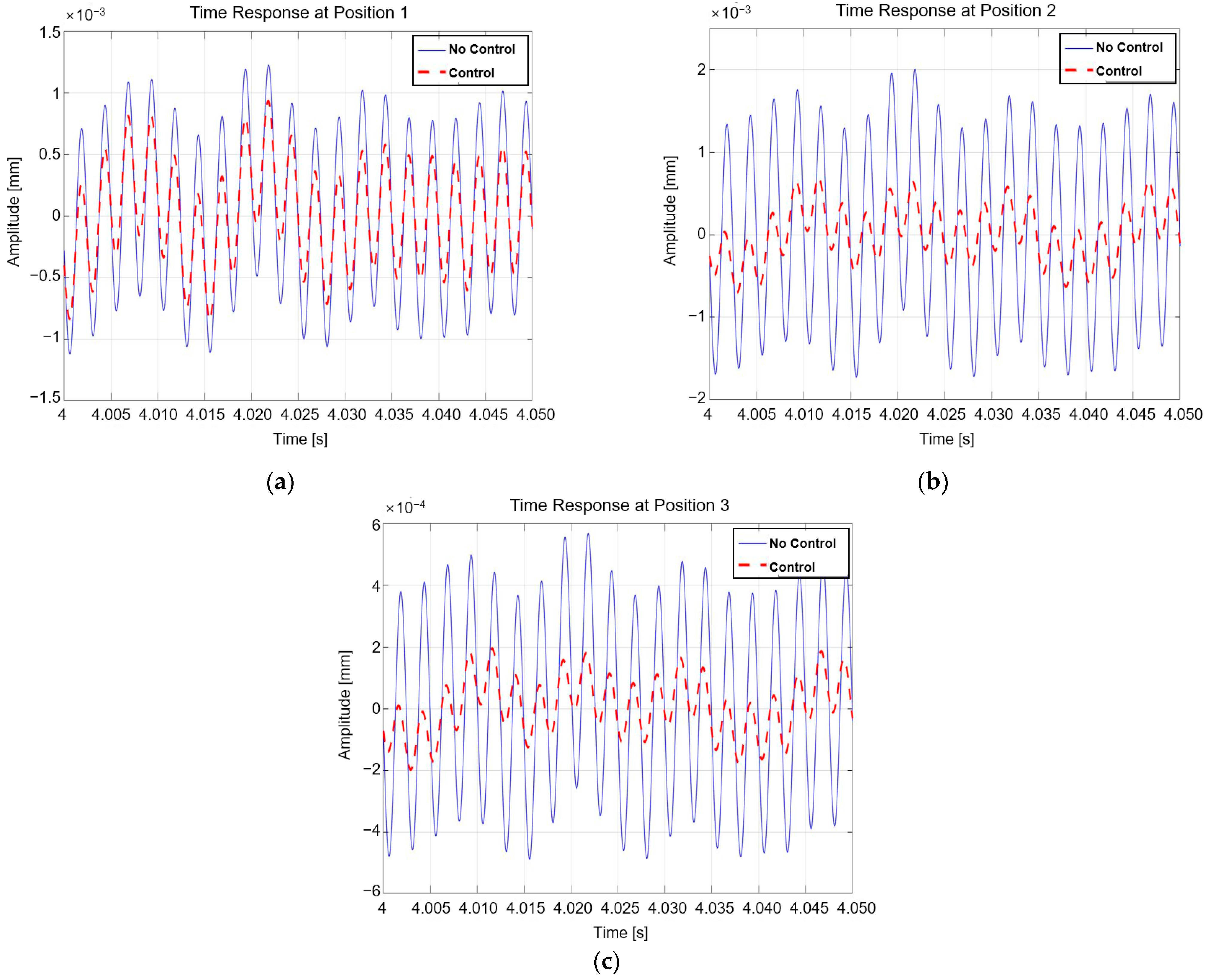
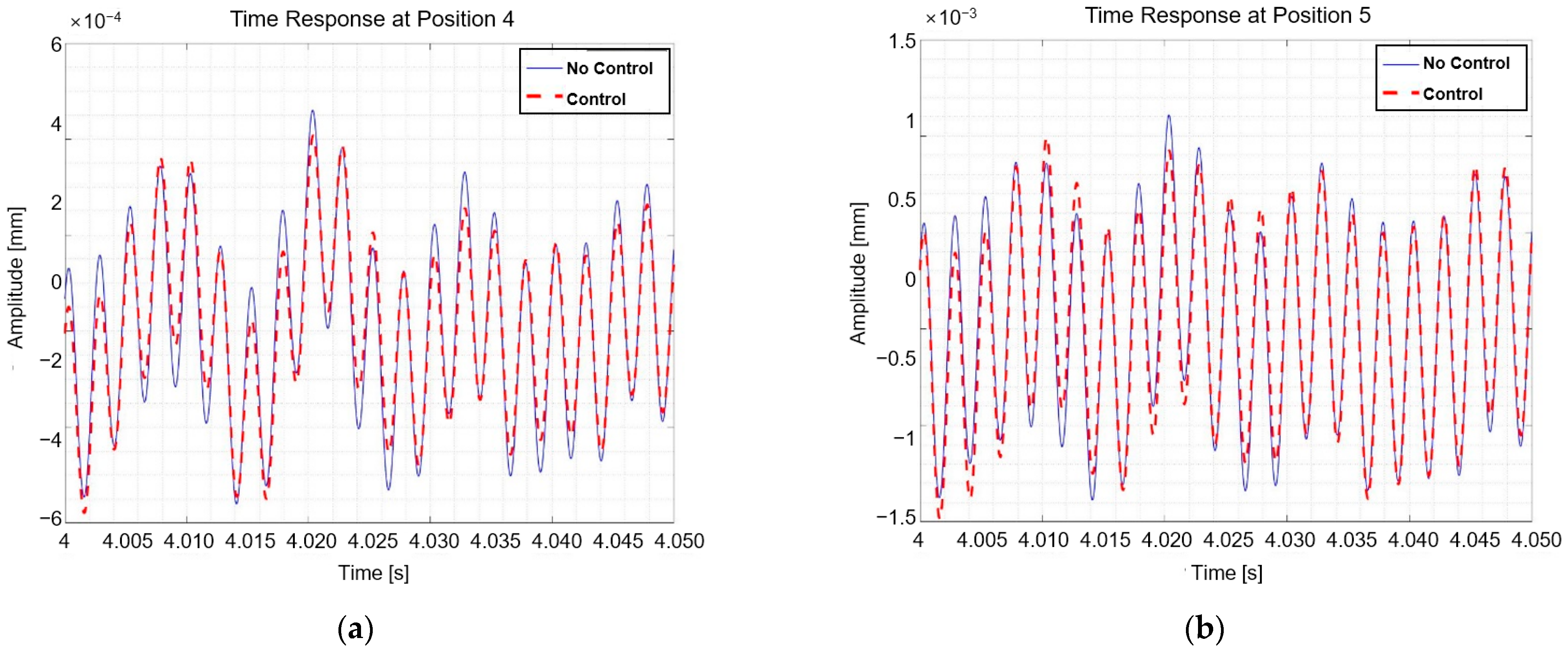
In the case of a simple sine wave excitation, the simulation produced the time domain response graphs in Figure 15 and Figure 16, a comparison of the RMS values of the time domain steady-state response before and after control in Table 6, and the frequency domain in Table 7. A comparison of the RMS values allowed us to determine the vibration-reduction efficacy.
As shown in Table 6, the vibration was reduced by 36.77% for M o u n t 1 s z , 69.5% for M o u n t 2 s z and M o u n t 2 s x , 6.5% for M o u n t 1 R z , and 1.69% for M o u n t 2 R z but not for M o u n t 2 R x , which declined by 3.54%. M o u n t 2 R x had an extremely low value before and after the control. Therefore, the M o u n t 2 R x results are excluded from the frequency domain results in Table 7. The vibration tended to be reduced by 43.97% in M o u n t 1 s z , 78.04% in M o u n t 2 s z and M o u n t 2 s x , 12.4% in M o u n t 1 R z , and 2.08% in M o u n t 2 R z . This suggests that the vibration and co-motion of the vehicle’s engine and subframe can be reduced. When the sinusoidal signal was excited, the NVH performance of the vehicle was enhanced through NLMS control.
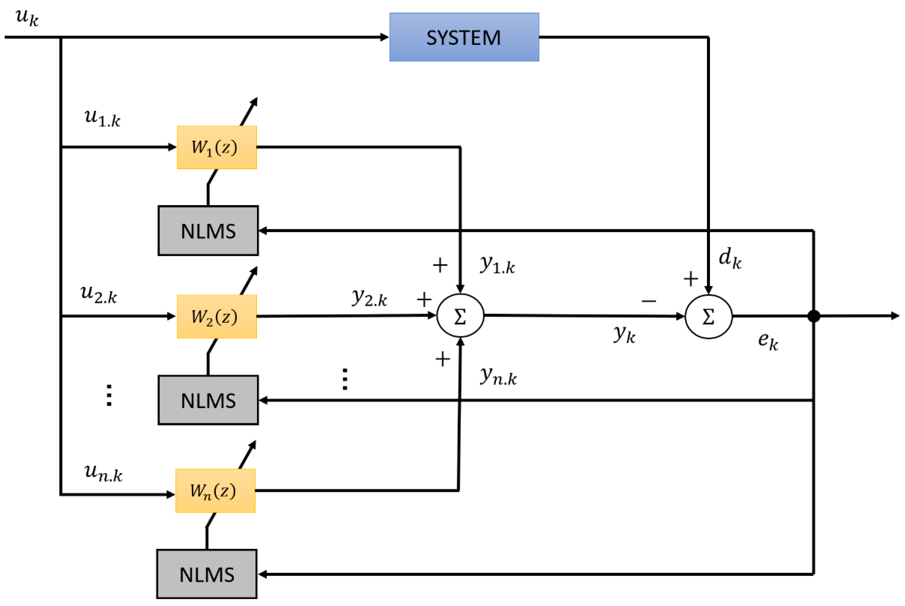
Due to the development of electric vehicles (EVs), vehicle powertrains produce signals with at least two to three frequencies. This indicates that it is difficult to control the system by calculating the secondary path input, as described in Section 2.3, or using the NLMS algorithm alone. Figure 17 illustrates that when AM and FM signals with multiple frequencies are excited, the multi-NLMS algorithm with multiple channels is used as a control.
When an input signal u k containing n frequency components enters the system, an NLMS filter is placed on each frequency component to modify the filter coefficient, and the signals for each frequency component are added to generate an output signal. This is a method for minimizing the signal errors.
Equation (41) defines the simulation input for the case in which the excitation force is an amplitude-modulated (AM) signal with a carrier frequency of 20 Hz, whose amplitude changes sinusoidally and has three frequency components.
u t = 5 s i n 400 × 2 π t 1 + c o s 20 × 2 π t
For each NLMS input, the frequency component of Equation (40) is inserted, as shown in Equations (42)–(44):
u 1 t = s i n 380 × 2 π t ,
u 2 t = s i n 400 × 2 π t ,
u 3 t = s i n 420 × 2 π t .
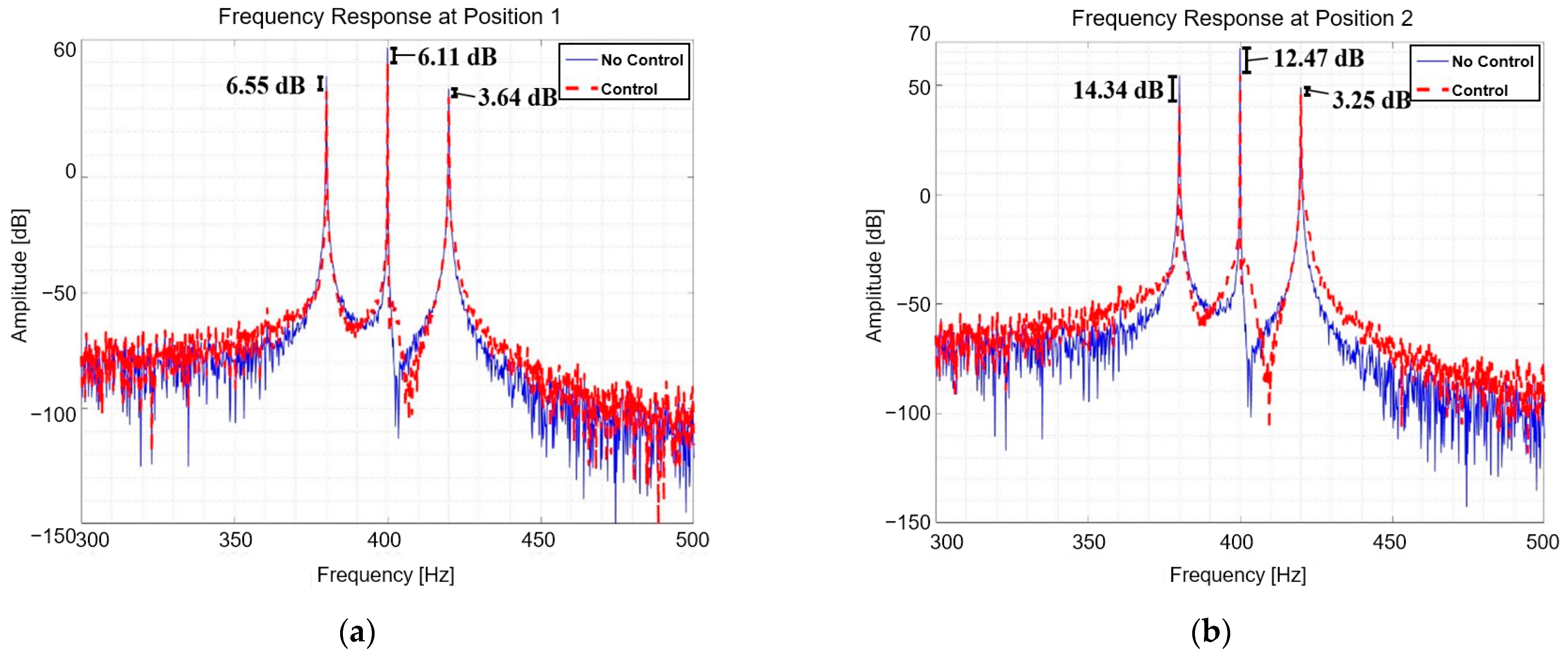
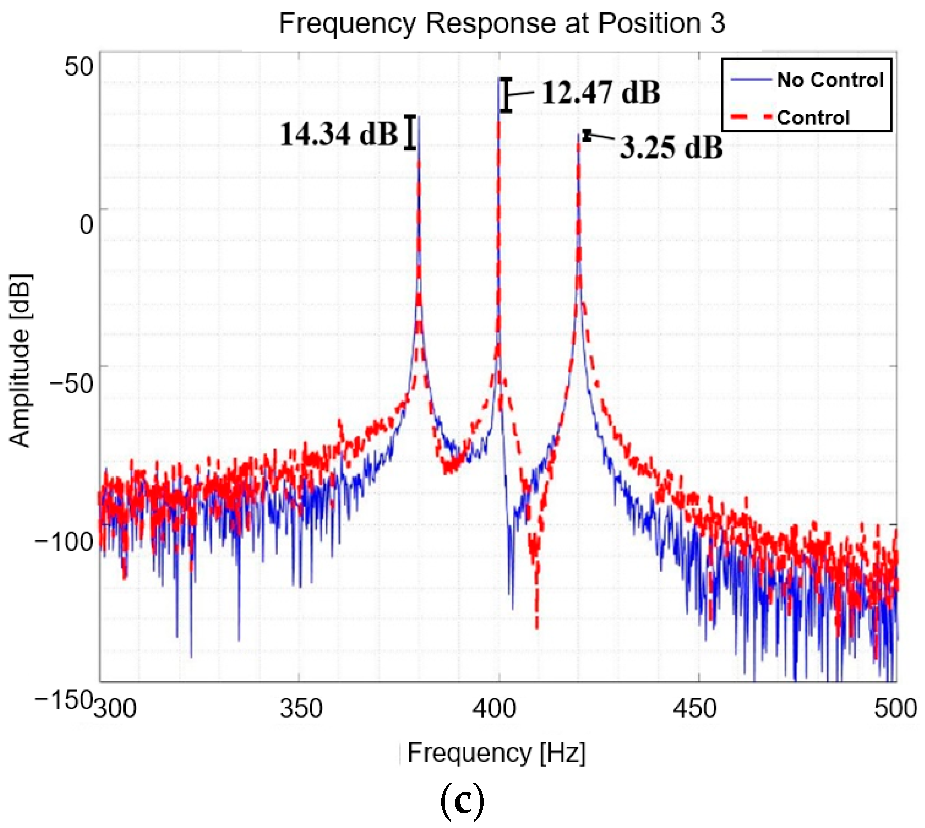
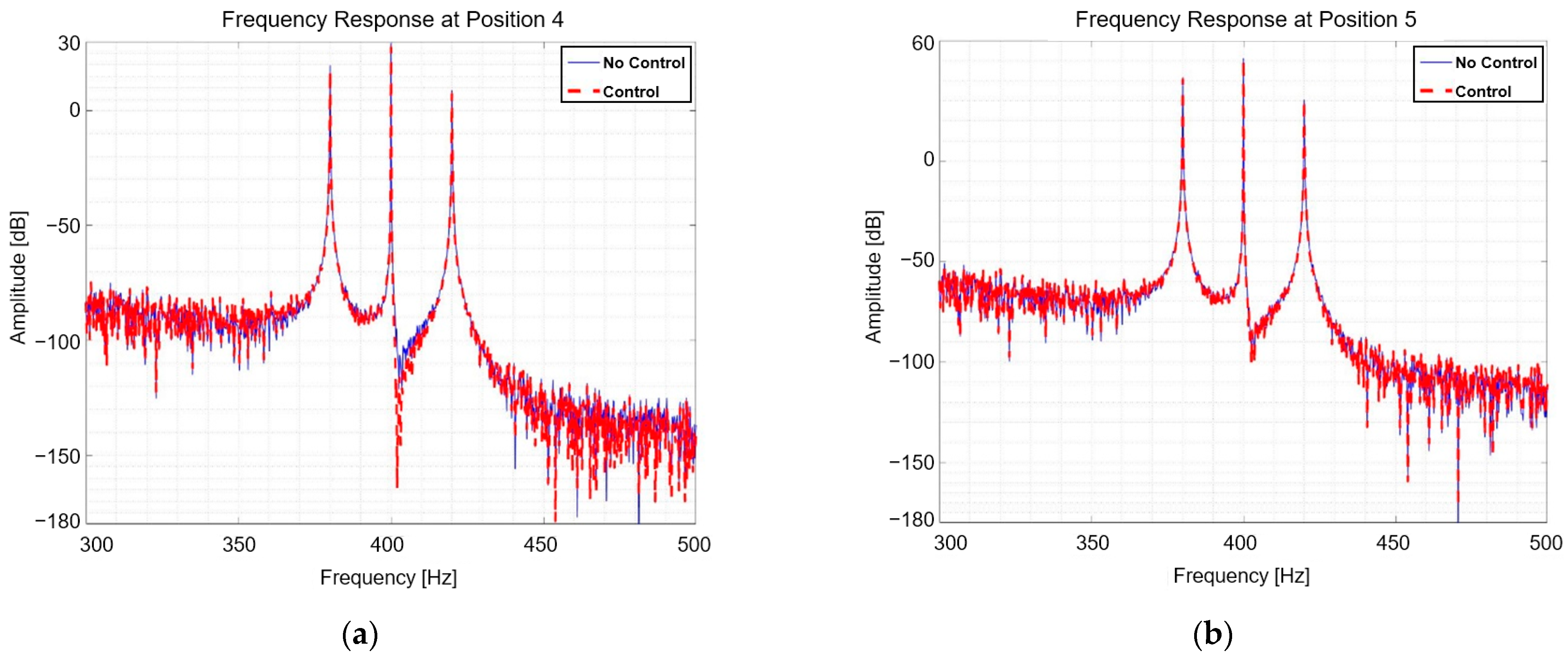
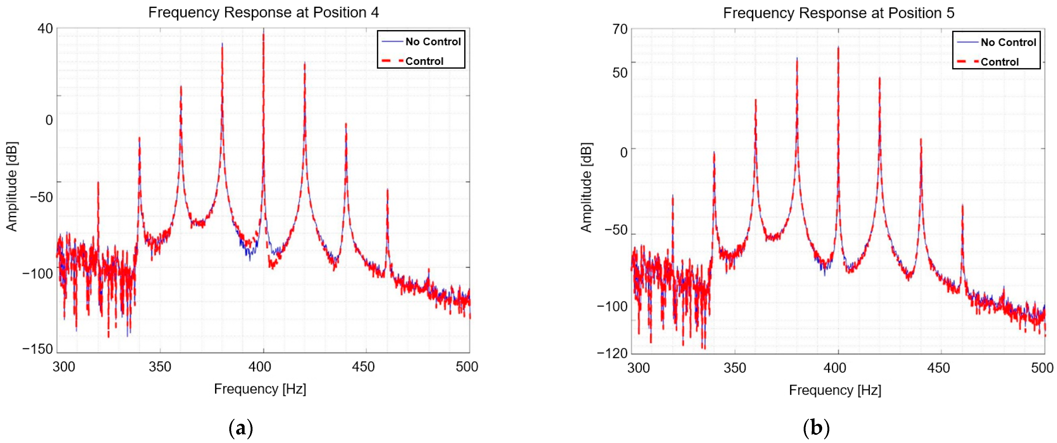
The generated signals were added and applied to the input of the secondary path via gain and phase controls. In contrast to sinusoidal signals, it is challenging to compare the responses of AM and FM signals in the time domain. Therefore, they were compared using frequency response graphs (FRF) using FFT. Figure 18 and Figure 19 depict the results of multi-NLMS control when the excitation force was an AM signal, as shown in the frequency response diagrams. In addition, the RMS responses in the time domain from 4 s to 4.05 s before and after control are compared at each position in Table 8.
In accordance with the time domain RMS results presented in Table 8, the vibrations tended to be reduced by 17.67% in M o u n t 1 s z , 37.95% in M o u n t 2 s z and M o u n t 2 s x , 2.55% in M o u n t 1 R z , and 3.09% in M o u n t 2 R z in comparison to before control. Nonetheless, it declined by 4.13% in M o u n t 2 R x . Moreover, the FRF RMS tended to reduce the vibration by 25.12% in M o u n t 1 s z , 41.48% in M o u n t 2 s z and M o u n t 2 s x , 8.63% in M o u n t 1 R z , and 2.52% in M o u n t 2 R z . When an AM signal is excited, it exhibits a tendency similar to a sinusoidal signal; however, its efficacy is poor. This indicates that the complex signal is excited, and the abatement performance is diminished. Based on the results, the vibration and loudness of the vehicle engine and subframe were reduced. When the AM signal was excited, the NVH performance of the vehicle was enhanced through NLMS control.
Equation (45) defines the simulation input for the case in which the excitation force is a frequency-modulated (FM) signal with a carrier frequency of 20 Hz, whose frequency is changing sinusoidally and ideally has an infinite number of frequency components.
u t = 10 c o s 400 × 2 π t + s i n 20 × 2 π t
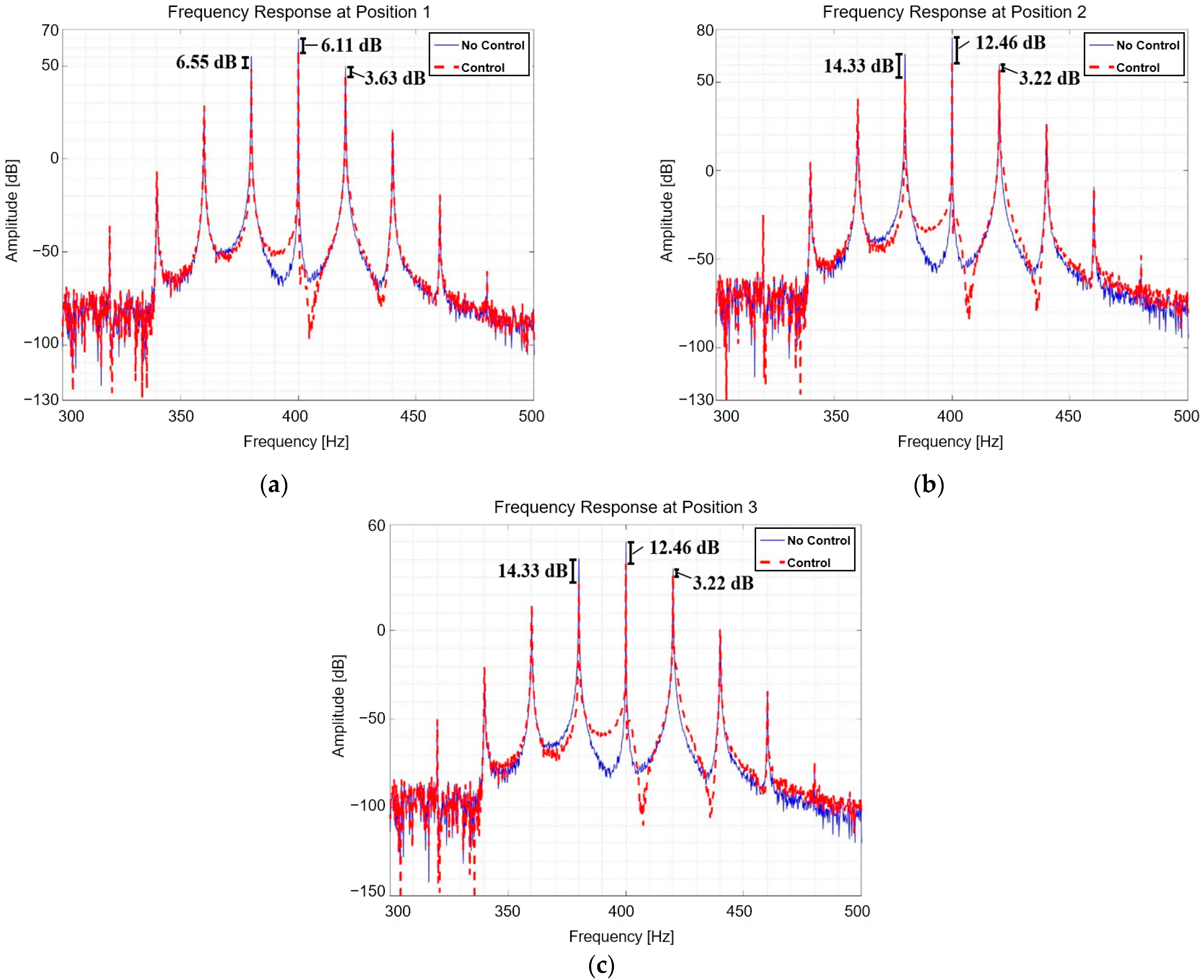
For each NLMS input, parts of the frequency components of Equation (45) are entered, as shown in Equations (42)–(44). Figure 20 and Figure 21 illustrate the frequency responses resulting from the application of the FM signals.
Using the time domain RMS values shown in Table 9, the vibrations were reduced by 21.42% in M o u n t 1 s z , 38.11% in M o u n t 2 s z and M o u n t 2 s x , 17.33% in M o u n t 1 R z , 5.34% in M o u n t 2 R z , and 5.34% in M o u n t 2 R x relative to the control. When the FM signal is excited, it exhibits a behavior similar to that of a sine wave or AM signal, but its performance is subpar. This indicates that the complex signal is excited, and the abatement performance is diminished. When the FM signal is excited, it can be seen that the control results reduce the vibration and commotion of the engine and subframe in the time domain and frequency domain. This demonstrates that when only the horizontal active mount is used the vibration reduction performance is inferior to that when both vertical and horizontal active mounts are employed; however, the NVH performance of the vehicle can be enhanced. If the vertically active mount fails, the vibration mitigation effect diminishes, necessitating repair [28].

4. Conclusions

In this study, an elastomer and a piezo actuator were used to build an engine mount between the engine and the vehicle subframe. The vibration-reduction performance was then assessed by orienting the device in the direction of the engine-mounted connection. The entire structure was conceived and simulated as a source–path–receiver, with the vehicle engine acting as the source, the active mount acting as the route, and the subframe acting as the receiver. Mathematical modeling was used to investigate the ability of the structure to reduce vibrations while utilizing both vertical and horizontal active mounts. Considering a situation in which the vertically active mount malfunctions or solely serves as a horizontally active mount, a six-degrees-of-freedom simulation was executed to examine the vibration reduction capabilities of the structure. When AM and FM signals with three frequency components were excited using the adaptive filter NLMS algorithm, the vibration reduction effect was verified in the case of a sinusoidal signal. This was achieved by determining the amplitude and phase required for each active mount.
Vibration-reduction performance decreases when only the horizontal active mount is the sole one used, and a control force larger than the excitation force is required. Furthermore, when the validation of the impact of the NLMS algorithm on vibration reduction during the excitation of complex signals and noise occurred, it was shown that, while the vibration conveyed to the receiver decreased less than that of the system with two active paths, the monitored source’s vibration was considerably reduced. As a result, if the vertical active mount fails, the model exhibits appropriate control power and control results only at the targeted position with generally negative effects on the other positions. The vibration of the subframe is judged to be on par with its pre-control level, requiring maintenance. It is possible to reduce the vibration of a structure effectively by applying a force in the horizontal direction, while further investigation is required to ascertain the relationship between the vertical and horizontal paths.
The contributions of this research are as follows:
(1)
A comprehensive methodology is proposed to analyze the vibrational behavior of mounting structures. This approach incorporates mathematical modeling and quantification of actuator inputs, enabling its applicability and expansion to encompass a wide range of mounting systems.
(2)
This study investigates and observes the interactions between vertical and lateral vibration of a structure inspired by an automotive mount. Previous research has predominantly concentrated on the actuation method and vibration attenuation in a single direction. Furthermore, the efficacy of vibration attenuation is evaluated and compared in relation to the specific positions employed to quantify actuator input. This would also contribute to the development of an actuation strategy.
(3)
Multi-spectral excitations are applied to the suggested structure to investigate the vibration reduction performance for relatively complicated vibration signals.
In future studies, because the actuator failure issue prevented the experiment from occurring, we will first validate each simulation by addressing this problem before experimenting. To enable more effective control, we also demonstrate how the connection orientation of the engine mount affects the source and receiver. Additionally, the performance of the proposed vibration reduction structure should be validated by considering both transient and steady-state conditions simultaneously. Eventually, this work should be applied to real-world applications to check its feasibility of vibration reduction with the consideration of actuator saturation.

Author Contributions

Conceptualization, B.K.; methodology, D.H. and H.M.; software, D.H. and H.M.; writing—original draft preparation, D.H. and H.M.; writing—review and editing, B.K. All authors have read and agreed to the published version of the manuscript.

Funding

This work was supported by a 2024 Yeungnam University Research Grant (224A380033) and by the Basic Science Research Program through the National Research Foundation of Korea (NRF) funded by the Ministry of Education (NRF-2021R1A6A1A03039493).

Data Availability Statement

The datasets used and/or analyzed during the current study are available from the corresponding author on reasonable request.

Conflicts of Interest

The authors declare no conflicts of interest.

References

  1. Yu, Y.; Naganathan, N.G.; Dukkipati, R.B. A literature review of automotive vehicle engine mounting systems. Mech. Mach. Theory 2001, 36, 123–142. [Google Scholar] [CrossRef]
  2. Hosseini, M.; Arzanpour, S.; Golnaraghi, F.; Parameswa-ran, A.M. Solenoid actuator design and modeling with application in engine vibration isolators. J. Vib. Control 2012, 19, 1015–1023. [Google Scholar] [CrossRef]
  3. Kraus, R.; Herold, S.; Millitzer, J.; Jungblut, T. Development of active engine mounts based on piezo actuators. ATZ Peer Rev. 2014, 116, 50–55. [Google Scholar] [CrossRef]
  4. Chae, H.D.; Choi, S.B. A new vibration isolation bed stage with magneto-rheological dampers for ambulance vehicles. Smart Mater. Struct. 2015, 24, 0964–1726. [Google Scholar] [CrossRef]
  5. Yang, T.J.; Suai, Z.J.; Sun, Y.; Zhu, M.G.; Xiao, Y.H.; Liu, X.G.; Du, J.T.; Jin, G.Y.; Liu, Z.G. Active vibration isolation system for a diesel engine. Noise Control Engr. J. 2012, 60, 267–282. [Google Scholar] [CrossRef]
  6. Jeon, J.; Han, Y.M.; Lee, D.Y.; Choi, S.B. Vibration control of the engine body of a vehicle utilizing the magneto-rheological roll mount and the piezostack right-hand mount. Proc. Inst. Mech. Eng. Part D J. Automob. Eng. 2013, 227, 1562–1577. [Google Scholar] [CrossRef]
  7. Jiang, J.; Gao, W.; Wang, L.; Teng, Z.; Liu, Y. Active vibration control based on modal controller considering structure actuator interaction. J. Mech. Sci. Technol. 2018, 32, 3515–3521. [Google Scholar] [CrossRef]
  8. Fakhari, V.; Choi, S.B.; Cho, C.H. A new robust adaptive con-troller for vibration control of active engine mount subjected to large uncertainties. Smart Mater. Struct. 2015, 24, 045044. [Google Scholar] [CrossRef]
  9. Elahinia, M.; Ciocanel, C.; Nguten, M.; Wang, S. MR and ER based semiactive engine mounts. Smart Mater. Res. 2013, 21, 831017. [Google Scholar] [CrossRef]
  10. Wu, W.; Chen, X. and Y. Shan. Analysis and experiment of a vibra-tion isolator using a novel magnetic spring with negative stiffness. J. Sound Vib. 2014, 333, 2958–2970. [Google Scholar] [CrossRef]
  11. Truong, T.Q.; Ahn, K.K. A new type of semi-active hydraulic engine mount using controllable area of inertia track. J. Sound Vib. 2010, 329, 247–260. [Google Scholar] [CrossRef]
  12. Kamada, T.; Fujita, T.; Hatayama, T.; Arikabe, T.; Murai, N.; Aizawa, S.; Tohyama, K. Active vibration control of frame structures with smart structures using piezoelectric actuators (vibration control by control of bending moments of columns. Smart Mater. Struct. 1997, 6, 448–456. [Google Scholar] [CrossRef]
  13. Loukil, T.; Bareille, O.; Ichchou, M.N.; Haddar, M. A low power consumption control scheme: Application to a piezostack-based active mount. Front. Mech. Eng. 2013, 8, 383–389. [Google Scholar] [CrossRef]
  14. Sui, L.; Shi, X.X.G. Piezoelectric actuator design and applica-tion on active vibration control. Phys. Procedia 2012, 25, 1388–1396. [Google Scholar] [CrossRef]
  15. Choi, S.B.; Choi, Y.T. Sliding mode control of a shear-mode type ER engine mount. KSME Int. J. 1999, 13, 26–33. [Google Scholar] [CrossRef]
  16. Sarkar, C.; Hirani, H.; Sasane, A. Magneto-rheological Smart Automotive Engine Mount. Int. J. Curr. Eng. Technol. 2015, 5, 419–428. [Google Scholar]
  17. Chang, Y.; Zhou, J.; Wang, K.; Xu, D. A quasi-zero-stiffness dynamic vibration absorber. J. Sound Vib. 2020, 494, 115859. [Google Scholar] [CrossRef]
  18. Liette, J.; Dreyer, J.T.; Singh, R. Interaction between two Paths for source mass motion control over mid-frequency range. J. Sound Vib. 2014, 333, 2369–2385. [Google Scholar] [CrossRef]
  19. Hong, D.; Kim, B. Vibration Reduction for Modulated Excitation Using Lumped Parameter Modeling and Multi-Channel NLMS Algorithm for a Structure with Three Active Paths between Plates. J. Mech. Sci. Technol. 2019, 33, 4673–4680. [Google Scholar] [CrossRef]
  20. Hong, D.; Kim, B. Quantification of Active Structural Path for Vibration Reduction Control of Plate Structure under Sinusoidal Excitation. Appl. Sci. 2019, 9, 711. [Google Scholar] [CrossRef]
  21. Qiu, Y.; Hong, D.; Kim, B. Optimal placement criteria of hybrid mounting system for chassis in future mobility based on beam-type continuous smart structures. Sci. Rep. 2023, 13, 2317. [Google Scholar] [CrossRef]
  22. Hausberg, F.; Scheiblegger, C.; Pfeffer, P.; Plöchl, M.; Hecker, S.; Rupp, M. Experimental and analytical study of secondary path variations in active engine mounts. J. Sound Vib. 2015, 340, 22–38. [Google Scholar] [CrossRef]
  23. Bartel, T.; Herold, S.; Mayer, D.; Melz, T. Development and Testing of Active Vibration Control Systems with Piezoelectric Ac-tuators. In Proceedings of the 6th ECCOMAS Conference on Smart Structures and Materials, Torino, Italy, 1–4 July 2013; pp. 24–26. [Google Scholar]
  24. Li, H.; Goodall, R.M. Linear and nonlinear skyhook damping control laws for active railway suspensions. Control Eng. Pract. 1999, 7, 843–850. [Google Scholar] [CrossRef]
  25. Singal, K.; Rajamani, R. Zero-Energy Active Suspension System for Automobiles with Adaptive Skyhook Damping. J. Vib. Acoust. 2013, 135, 011011. [Google Scholar] [CrossRef]
  26. Emura, J.; Kakizaki, S.; Yamaoka, F.; Nakamura, M. Development of the Semi-Active Suspension System Based on the Skyhook Damper Theory. SAE Trans. J. Passeng. Cars 1994, 103, 1110–1119. [Google Scholar]
  27. Chai, Y.; Li, F.; Song, Z.; Zhang, C. Analysis and active control of nonlinear vibration of composite lattice sandwich plates. Nonlinear Dyn. 2020, 102, 2179–2203. [Google Scholar] [CrossRef]
  28. Hong, D.; Moon, H.; Kim, B. Bidirectional active vibration control of two-dimensional structure inspired by automotive engine mounting system. J. Mech. Sci. Technol. 2024, 38. in press. [Google Scholar]
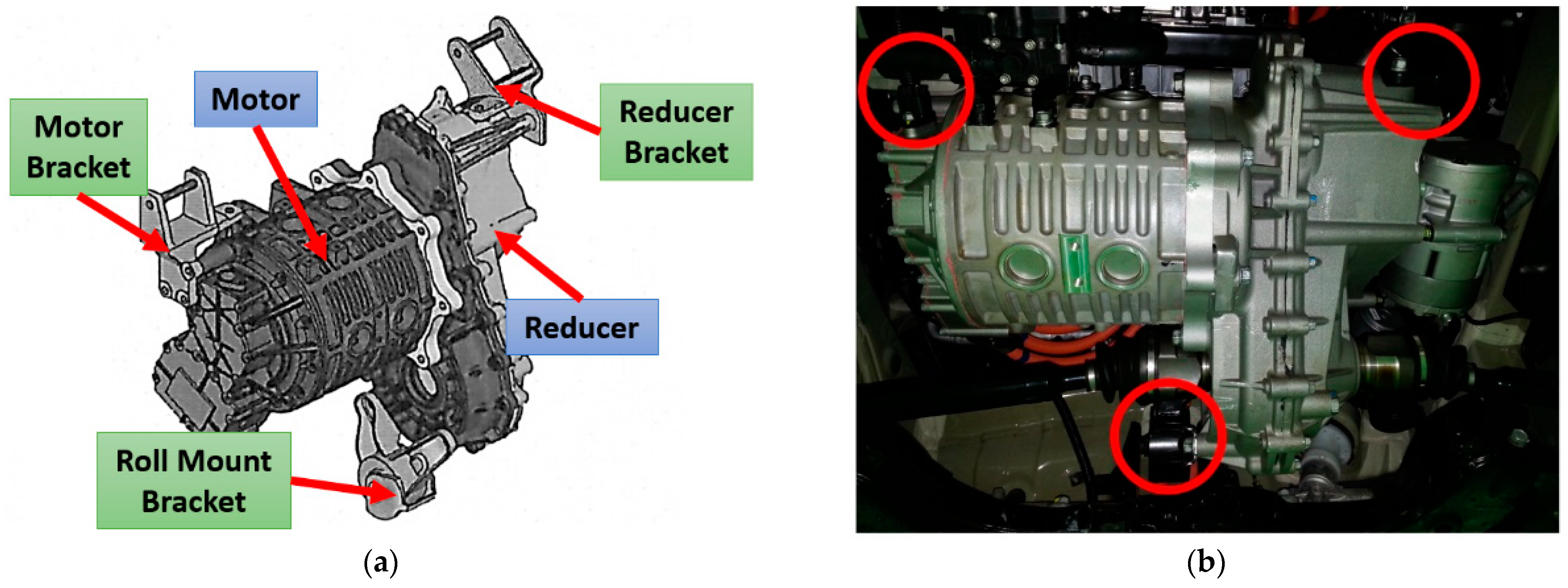
Figure 1. (a) EV powertrain mounts; (b) EV mounting system.
Actuators 13 00171 g001
Figure 2. Application of active vibration control system in automotive mounts.
Actuators 13 00171 g002
Figure 3. Model of mounting system with defective vertical active path allowing multidirectional installation.
Actuators 13 00171 g003
Figure 4. Model of mounting system allowing multidirectional installation using mount coordinates.
Actuators 13 00171 g004
Figure 5. Dynamic movement of source via external force.
Actuators 13 00171 g005
Figure 6. Dynamic movement of receiver via external force.
Actuators 13 00171 g006
Figure 7. The configuration used in the experiment to determine the parameters.
Actuators 13 00171 g007
Figure 8. Response in steady state for harmonic excitation.
Actuators 13 00171 g008
Figure 9. Model schematic for simulation.
Actuators 13 00171 g009
Figure 10. Steady-state response controlled by Case 1.
Actuators 13 00171 g010
Figure 11. Steady state response controlled by Case 2.
Actuators 13 00171 g011
Figure 12. Steady state response controlled by Case 3.
Actuators 13 00171 g012
Figure 13. Steady state response controlled by Case 4.
Actuators 13 00171 g013
Figure 14. 6-DOF NLMS control simulation schematic.
Actuators 13 00171 g014
Figure 15. Time domain comparison of NLMS control source in case of sine wave: (a) position 1; (b) position 2; and (c) position 3.
Actuators 13 00171 g015
Figure 16. Time domain comparison of NLMS control source in case of sine wave: (a) position 4 and (b) position 5.
Actuators 13 00171 g016
Figure 17. Multi-NLMS algorithm schematic diagram.
Actuators 13 00171 g017
Figure 18. Comparison of FRF of NLMS control in case of AM signal: (a) position 1; (b) position 2; and (c) position 3.
Actuators 13 00171 g018aActuators 13 00171 g018b
Figure 19. Comparison of FRF of NLMS control in case of AM signal: (a) position 4 and (b) position 5.
Actuators 13 00171 g019
Figure 20. Comparison of FRF of NLMS control in case of FM signal: (a) position 1; (b) position 2; and (c) position 3.
Actuators 13 00171 g020
Figure 21. Comparison of FRF of NLMS control in case of FM signal: (a) position 4 and (b) position 5.
Actuators 13 00171 g021
Table 1. Variable values and units applied to 6-degrees-of-freedom simulation.
VariableValueUnitVariableValueUnit
m 1 1.721 k g c m 2 z = c m 2 x = c m 2 z x 140 N s / m
m 2 1.350 k g c m 3 z 64 N s / m
m a c 1 0.075 k g c b 1 z = c b 2 z 200 N s / m
I 1 33.402 g m 2 l s 1 = l s 3 50.686 m m
I 2 18.070 g m 2 l s 2 179.314 m m
k m 1 z 5.46 k N / m m l r 1 = l r 2 136 m m
k m 2 z = k m 2 x = k m 2 z x 0.5 k N / m m l r 3 = l r 5 0 m m
k m 3 z 0.61 k N / m m l r 4 200 m m
k b 1 z = k b 2 z 0.42 k N / m m d 50 m m
c m 1 z 22 N s / m
Table 2. Comparison of results before and after Case 1 control.
[Unit: μ m ]SOURCERECEIVER
P1P2P3P4P5_vertP5_horiz
Before
Control
0.62911.06680.30150.08020.2425 2.39 × 10 7
After
Control
0
100%
0.9169
14.04%
0.2592
14.04%
0.1144
42.66%
0.2339
3.54%
2.49 × 10 7
4.22%
Table 3. Comparison of results before and after Case 2 control.
[Unit: μ m ]SOURCERECEIVER
P1P2P3P4P5_vertP5_horiz
Before
Control
0.62911.06680.30150.08020.2425 2.39 × 10 7
After
Control
2.1016
234%
5.7085
435.2%
1.6136
435.2%
0
100%
0.2676
10.36%
2.19 × 10 7
8.43%
Table 4. Comparison of results before and after Case 3 control.
[Unit: μ m ]SOURCERECEIVER
P1P2P3P4P5_vertP5_horiz
Before
Control
0.62911.06680.30150.08020.2425 2.39 × 10 7
After
Control
0.2910
53.75%
0
100%
0
100%
0.0986
22.97%
0.238
1.85%
2.45 × 10 7
2.46%
Table 5. Comparison of results before and after Case 4 control.
[Unit: μ m ]SOURCERECEIVER
P1P2P3P4P5_vertP5_horiz
Before
Control
0.62911.06680.30150.08020.2425 2.39 × 10 7
After
Control
6.0759
865.8%
19.4799
1726%
5.5063
1726%
0.3778
371%
0
100%
0
100%
Table 6. Comparison of steady-state RMS results before and after NLMS control.
[Unit: μ m ]SOURCERECEIVER
P1P2P3P4P5_vertP5_horiz
Before
Control
0.65361.09230.30880.18820.5118 5.49 × 10 7
After
Control
0.4133
36.77%
0.3332
69.5%
0.0942
69.5%
0.176
6.5%
0.5032
1.69%
5.69 × 10 7
3.54%
Table 7. Comparison of FRF RMS results before and after NLMS control.
[Unit: m m ]SOURCERECEIVER
P1P2P3P4P5_vert
Before
Control
1.05881.79530.50750.27360.8159
After
Control
0.5933
43.97%
0.3942
78.04%
0.1114
78.04%
0.2397
12.4%
0.7989
2.08%
Table 8. Comparison of steady-state RMS results before and after NLMS control (AM).
[Unit: μ m ]SOURCERECEIVER
P1P2P3P4P5_vertP5_horiz
Before
Control
0.42450.69530.19650.13910.3455 2.94 × 10 7
After
Control
0.3495
17.67%
0.4315
37.95%
0.122
37.95%
0.1356
2.55%
0.3348
3.09%
3.06 × 10 7
4.13%
Table 9. Comparison of steady-state RMS results before and after NLMS control (FM).
[Unit: μ m ]SOURCERECEIVER
P1P2P3P4P5_vertP5_horiz
Before
Control
0.65701.10100.31120.19500.5336 6.39 × 10 7
After
Control
0.5162
21.42%
0.6813
38.11%
0.1926
38.11%
0.1854
4.91%
0.5196
2.61%
6.05 × 10 7
5.34%
Disclaimer/Publisher’s Note: The statements, opinions and data contained in all publications are solely those of the individual author(s) and contributor(s) and not of MDPI and/or the editor(s). MDPI and/or the editor(s) disclaim responsibility for any injury to people or property resulting from any ideas, methods, instructions or products referred to in the content.