Article

Light-Weighting and Comparative Simulation Analysis of the Forearm of Welding Robots

School of Mechanical Engineering, Guangdong Ocean University, Guangdong Engineering Technology Research Center of Small Household Appliances Innovation Design and Manufacturing, Zhanjiang 524088, China
*
Author to whom correspondence should be addressed.
Actuators 2024, 13(6), 209; https://doi.org/10.3390/act13060209
Submission received: 10 May 2024 / Revised: 29 May 2024 / Accepted: 31 May 2024 / Published: 4 June 2024
(This article belongs to the Section Actuators for Robotics)

Abstract

:
The light-weighting of a robotic arm is an important aspect of robot research. In the operation of existing welding robots, excessive vibrations in the welding actuators have been observed, which lead to reduced welding precision and work efficiency. The direct connection between the forearm and the welding actuator is a key component that affects vibrations. Based on this, a study on light-weighting the forearm is proposed. Using the theory of topology optimization with variable density structure, the structural dimensions, shapes, and geometric parameters of the forearm are optimized. The material removal methods of “hole cutting” and “local hollowing” are employed to reconstruct the forearm structure model. Static, modal, and transient simulations were performed on the forearm model pre-optimization and post-optimization. The optimization results show that the mass of the forearm is reduced by 19.8%. The static simulation comparative analysis shows that, under the same constraints and load conditions, the maximum total deformation of the optimized forearm is reduced by 3.6%, the maximum stress is reduced by 3.2%, and the maximum equivalent elastic strain is reduced by 5.7%. The optimized forearm structure is more reasonable and exhibits better mechanical performance. Modal simulation comparative analysis shows that the first and second natural frequencies of the optimized forearm are increased by 9.8% and 7.0%, respectively. Transient simulation comparative analysis demonstrates that, under the maximum operating condition, the vibration frequency and amplitude of the optimized welding robot forearm are reduced by 19.4% and 26.9%, respectively. The maximum amplitudes of the maximum equivalent stress curve and maximum equivalent elastic strain curve are reduced by 51.0% and 46.0%, respectively. This study provides a guarantee for reducing vibrations in welding actuators, improving welding precision, and enhancing the work efficiency of the welding robot.

1. Introduction

The robotic arm is a crucial component of robots, and its mass has a significant impact on the overall performance of the robot. Light-weighting is a key research area in robotic arm design, and researchers from both domestic and international communities have employed various design methods to achieve light-weighting. For instance, Albuschaffer et al. replaced traditional metal materials with high-strength carbon fiber to reduce the total mass of the DLR robot [1]. HAIBIN YIN et al. proposed a design method based on a CFRP/AA (Carbon Fiber-Reinforced Plastic and Aluminum Alloy) hybrid structure to reduce the mass of the robotic arm, resulting in a lighter overall structure of the robot [2]. Gökçe Mehmet Gençer et al. directly combined the aluminum alloy (AA7075) with composite material (glass fiber reinforced PA66) to manufacture a hybrid structure with scarf joint configuration, achieving light-weighting and reduced vibrations compared to the single-material robotic arm [3]. Considering that light-weighting materials are often expensive and difficult to process [4], researchers tend to utilize topology optimization methods for their light-weighting design [5]. Jiguang Jia et al. proposed an integrated optimization method that combines topology and size parameters (TPOM). By setting key variables that link topology layout with size characteristics, the structural mass of the robotic arm was reduced while maintaining structural stiffness [6]. Yin et al. proposed a light-weighting method for the robotic arm with parameterized design variables of structural size and the transmission system. The optimization results demonstrated the effectiveness of this method in reducing the mass of the robotic arm [7]. Mingxuan Liang et al. applied topology optimization with light-weighting as the design objective and total displacement of the robot arm end as the constraint. They combined a flexible multibody dynamics model, finite element method, and topology optimization theory to optimize the robotic arm structure [8]. Jiguang Jia et al. proposed a topology and size parameter-integrated optimization method (TPOM), which establishes a connection between the topology layout and size features by setting key variables. This method reduces the structural mass of the robotic arm while maintaining structural stiffness [6]. Luo H proposed a design method for the plunger structure of a Friction Stir Welding (FSW) robot based on finite element analysis. By considering the static and dynamic characteristics, the plunger structure was optimized to achieve a lightweight design, thereby improving the welding accuracy of the FSW robot [9]. Mingxuan Liang et al. aimed at lightweight design and used the total displacement of the end effector as a constraint. They combined flexible multibody dynamics, finite element analysis, and the topology optimization theory to perform topology optimization of the robotic arm [8]. Topology optimization does not simply modify existing structures but provides new structural layouts. It enables rapid identification of optimal material distribution under specified conditions [10] and maximizes stiffness under mass constraints, thereby effectively shortening product development cycles [11]. Topology optimization methods mainly include homogenization methods [12], density-based methods [13], evolutionary structural optimization (ESO) methods [14], level-set methods [15], deformable void methods, and moving morphable void (MMV) methods [16].
This study contributes to the literature on the optimization of the welding robot forearm. In contrast to previous studies, this research introduces a novel approach by incorporating the density-based topology optimization method to achieve the lightweight design of the welding robot forearm, thereby improving its mechanical performance and vibration characteristics. Initially, the forearm undergoes topology optimization using the density-based method. Subsequently, based on the analysis results, the model is reconstructed by removing unnecessary materials through “voiding” and “cutting” procedures to optimize its physical properties. This paper conducts a comparative analysis through static and dynamic simulations pre- and post-optimization to assess enhancements in the static and dynamic performance of the welding robot forearm. The results indicate that the integration of the density-based topology optimization method leads to a significant reduction in the weight of the forearm and improves both its static and dynamic performance.
The structure of this study is as follows: the second section introduces the principle of the density-based topology optimization method; the third section applies the density-based method to optimize the structure of the welding robot forearm; the fourth section conducts a comparative analysis through simulations pre- and post-optimization based on the analytical results.
Current industrial welding robots often exhibit excessive vibrations in the welding actuators during operation, which not only reduces welding efficiency and precision but also decreases overall stability and service life. The welding robot mainly consists of a base, upper arm, joint axes, forearm, wrist, and welding actuators, as shown in Figure 1, provided by an enterprise. The forearm, directly connected to the welding actuator, plays a vital role in the welding efficiency and precision of the welding robot. The forearm consists mainly of the shaft and the main body of the forearm. Therefore, this study aimed to achieve the light-weighting of the forearm by utilizing the variable density method to optimize the structural dimensions, shape, and topology parameters. Static, modal, and transient simulations were conducted to compare and analyze the forearm pre- and post-optimization, with the goal of achieving light-weighting, improved mechanical characteristics, and dynamic performance of the forearm.

2. Topology Optimization Theory Analysis of the Forearm

Based on the structural characteristics of the forearm, the density-based topology optimization method is adopted. The forearm is discretion into several finite elements, and design objectives and constraints are given to determine the optimal distribution and transmission path of structural materials in the forearm [17] in order to optimize the structure’s quality and performance. The material interpolation model is defined as follows:
E ( ρ i ) = ( ρ i ) p E 0
In the equation, E(ρi) represents the interpolated elastic modulus of the forearm, E0 is the elastic modulus of the solid material of the forearm, p is the penalty factor for the forearm material, and ρi represents the relative density of the i-th element. The density-based method assumes that the stiffness matrix of each element depends on the variation in the penalty factor p and the relative density ρi, establishing a nonlinear relationship between the relative density and the elastic modulus of the material. By introducing the penalty factor p to adjust the intermediate density value ρi of the material, the stiffness of the structure is gradually penalized, causing intermediate density to converge towards the ends of 0~1, thus changing the elastic modulus E of the elements and subsequently altering the stiffness matrix K of the material. This ultimately enables the planning of material distribution and transmission paths. According to the theory of mechanical vibration, the forearm of the welding robot can be regarded as a vibrating system, with its basic dynamic equation given as follows:
M x + C x + K x = F ( t )
In the equation, M represents the mass matrix of the forearm, C is the damping matrix, K is the stiffness matrix, F(t) is the externally applied force, x″ is the acceleration vector, x′ is the velocity vector, and x is the displacement vector of the forearm.
The basic idea of density-based methods is to assume the existence of density-variable material elements that do not exist in actual engineering. It combines the concept of discrete topology optimization modeling. In this method, the density of material elements is set as a continuous variable, with values ranging from 0 to 1. Additionally, a function relationship between the density of material elements and the physical properties of the material needs to be defined to express the density function of material elements.
In topology optimization, the aim is to maximize the stiffness of the forearm. To achieve this goal, the relative density of material elements in the welding robot forearm can be treated as a design variable, while the volume fraction of material optimization serves as a constraint. By seeking a rational material distribution, the optimization of the forearm structure can be achieved. In the process of topology optimization, the lower limit of the relative density of material elements is set between 0 and 1. If the relative density of a material element is lower than the lower limit, it indicates that the material contribution to the stiffness of the forearm at that location is the forearm and can be removed. Conversely, if the relative density of a material element is higher than the lower limit, it indicates that the material contribution to the stiffness of the forearm at that location is significant and should be retained [18].
Taking the example of topology optimization for continuous structures with a global volume constraint, the model for the topology optimization problem based on the density-based method can be described as follows:
F i n d : ρ = { ρ 1 , ρ 2 , ρ 3 , ρ n } T Ω M i n i m i z e : C = F T U S u b j e c t t o : V f V : F = K U : 0 < ρ min < ρ i < 1 ( i = 1 , 2 , 3 , n )
In the equation, ρ represents the relative density of the material element, which is the design variable in the topology optimization problem. Its value is a continuous value between [ρmin, 1], where ρmin is typically set to a forearm value close to “0” (e.g., 0.01). This is performed to avoid singularity in the stiffness matrix during the finite element calculation.
In the field of topology optimization, two commonly used density interpolation models are SIMP (Solid Isotropic Material with Penalization) and RAMP (Rational Approximation of Material Properties). In terms of the penalty effect on intermediate density, the SIMP interpolation model performs slightly better than the RAMP interpolation model. In this study, the solution method for the topology optimization problem of continuous structures was mainly derived under the SIMP modeling method [19]. It used the power exponent P of artificial material density to penalize the intermediate density, aiming to make the density of the material in the optimization process tend towards “0” or “1” as much as possible.
In the SIMP material interpolation model, the density of the artificial material element is represented as follows:
ϕ ( x i ) = x i p , x i [ x min , 1 ] , i = 1 , 2 , 3 , n
Assuming the material is isotropic, and Poisson’s ratio for the material is a constant independent of the material density, the relationship between the density of the artificial material element and the elastic modulus of the material can be established as follows:
E ( x i ) = E min + ϕ ( x i ) ( E E min ) = E min + Δ E x i p , Δ E = E E min , i = 1 , 2 , 3 , n
To ensure numerical stability, the minimum value of the elastic modulus E min is set to E/1000, and it satisfies 0 < EminE(xi) ≤ E, where E(xi) represents the elastic modulus of element i in the structure, E is the elastic modulus of the material element with density “1”, Emin is the elastic modulus of the low-strength material element, and xi represents the relative density of each element.
To ensure the accuracy of the optimization results and consider the maneuverability of the forearm, a penalty factor P is introduced in the SIMP (Solid Isotropic Material with Penalization) model to adjust the intermediate material density. The adjusted material density values converge more quickly towards “0” or “1”, allowing the SIMP model to better approximate the topology optimization model based on discrete variables. In Equation (5), the elastic modulus of any material element in the structure is determined by the material density interpolation function φ(xi), where different penalty factors P and different intermediate densities xi jointly determine the convergence of the material element’s elastic modulus towards 0 or E.
Considering the global volume constraint, the topology optimization problem for continuous structures is formulated based on the minimum compliance (maximum stiffness or minimum strain energy) criterion. The compliance function for continuous structures is derived based on the SIMP model as follows:
C ( x i ) = F T U = U T K U = i = 1 n u i T k i u i
Here, Emin << E, Equation (5) can be transformed into the following:
E ( x i ) = E min + x i p ( E E min ) = x i p E
The value k* for the material unit stiffness matrix k put forward its own modulus of elasticity E(xi) to obtain the unit stiffness matrix, k0; for the density of the material for “1” unit stiffness matrix, its elastic modulus is E, which combined with Formula (7) then produces the following:
k i = E ( x i ) k = x i p E k = x i p k 0
By substituting Equation (8) into Equation (6), the function form of the compliance of the structure after finite element discretization can be obtained:
C ( x i ) = i = 1 n x i p u i T k 0 u i
Based on the SIMP material interpolation model, the topology optimization problem for flexibility minimizing continuum structures under structural volume constraints can be described as follows:
F ind : X = { x 1 , x 2 , x 3 , , x n } T Ω M i n i m i z e : C ( x ) = F T U = U T K U = i = 1 n x i p u i T k 0 u i S u b j e c t t o : i = 1 n x i v i f V 0 : F = K U : 0 < x min x i 1 , ( i = 1 , 2 , 3 , , n )
In Equation (10),
X—material element relative density, which serves as the design variable for the entire optimization model.
C(x)—objective function.
F—load vector.
U—material element displacement column vector.
f—remaining material percentage.
V—volume of the structural material.
vi—the relative volume of the material element.
xmin—minimum material element density, typically set to 0.01.
xmax—maximum material element density.
xi—relative density of the element under consideration.
K—stiffness matrix of the material element with density “1”.

3. Lightweight Topology Optimization of the Forearm

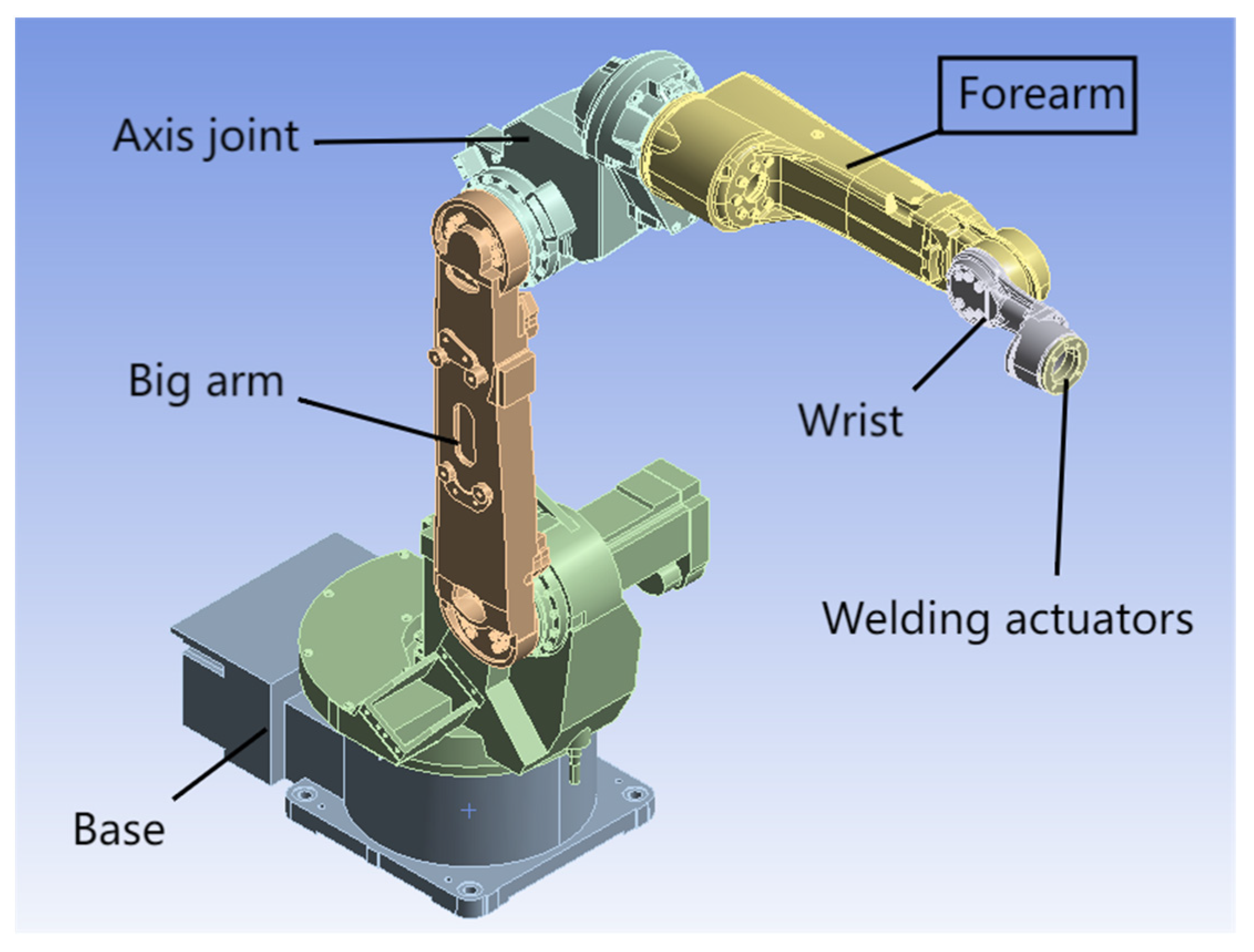
3.1. Geometric Dimensions and Material Characteristics of the Forearm

The geometric dimensions of the robot forearm are shown in Table 1. The upper arm is made of Ai5083 material, and its material properties are listed in Table 2.

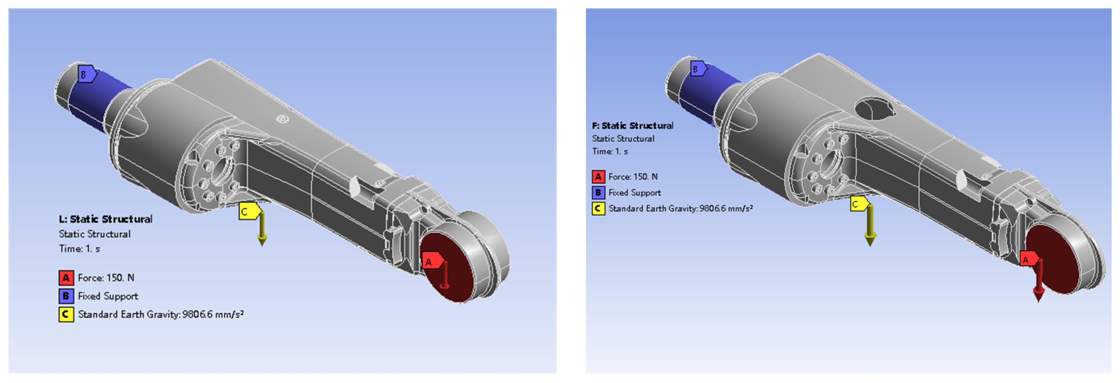
3.2. Boundary Conditions and Optimization Parameter Settings

Constraints are applied at the front end of the forearm connecting shaft, while a force load is applied at the end of the forearm (in practical applications, the weight of the welding actuator is ≤150 N, taken as the maximum value). Except for the constrained and loaded regions, the remaining positions of the forearm are designated as the optimization area. The objective function, C(ρ), is defined for minimization using a density-based optimization algorithm. The penalty factor, p, for density, is typically set between 3 and 5. In this optimization, p is set to 3. The minimum normalized density of the material element is set to 0.001, and the convergence criterion is set to 0.1%. The density threshold, ρ, is set to 0.01. The maximum number of iterations in the iterative calculation process is set to 500. Among other conditions, the minimization of compliance and minimum equivalent stress are considered. The optimization region is defined using the constraint of mass as the response, with a retention percentage of 50%.

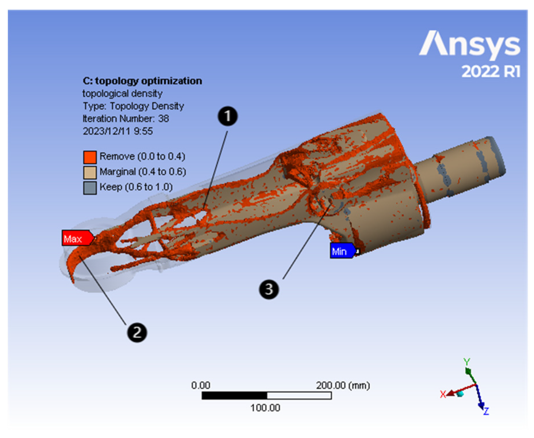
3.3. Topology Optimization Results and Structural Model Reconstruction

Using the ANSYS Workbench platform, the forearm model was meshed, and topology optimization for light-weighting was performed. After iterative convergence of the objective function, the optimization region was calculated, and all set objectives were achieved near the convergence criteria and stabilized. The obtained density distribution of the optimized forearm is shown in Figure 2. Regions with high density indicate areas where material must be retained, while regions with low density indicate areas where the material can be removed. According to Figure 2, the redundant material distribution of the forearm is observed, with a concentration of weight reduction in locations ① and ③. In order to reduce the mass of the welding robot’s forearm and to remove material from the optimized position of the structural topology, this paper uses the methods of “hole-cutting” and “local cavity excavation “with the aim of being able to reduce the mass according to the exact position and to reduce the stress concentration”. Based on the methods of “hole cutting” and “local cavity excavation,” the forearm model was reconstructed to remove the redundant volume. At location ①, hole cutting was employed to remove a portion of the redundant material. At location ②, where the load was relatively forearm, a local cavity was excavated. At location ③, hole cutting and internal material excavation were performed.
Considering the practical needs of mechanical processing technology and assembly space layout, the reconstructed forearm structural model is shown in Figure 3. At location ① in Figure 3, hole cutting was performed, resulting in a shape composed of a semicircle with a radius of 35 mm and a rectangle measuring 138 mm in length and 70 mm in width. At location ② in Figure 3, a local cavity with a radius of 56.42 mm and a height of 37.5 mm was excavated, including the connected bolts. At location ③ in Figure 3, hole cutting with a diameter of 52 mm and internal material excavation were performed.
Through the topology optimization and model reconstruction mentioned above, the mass of the forearm was reduced from 7.493 kg to 6.007 kg, which is a significant reduction of 19.8% in lightweight design.

4. Simulation Results Analysis

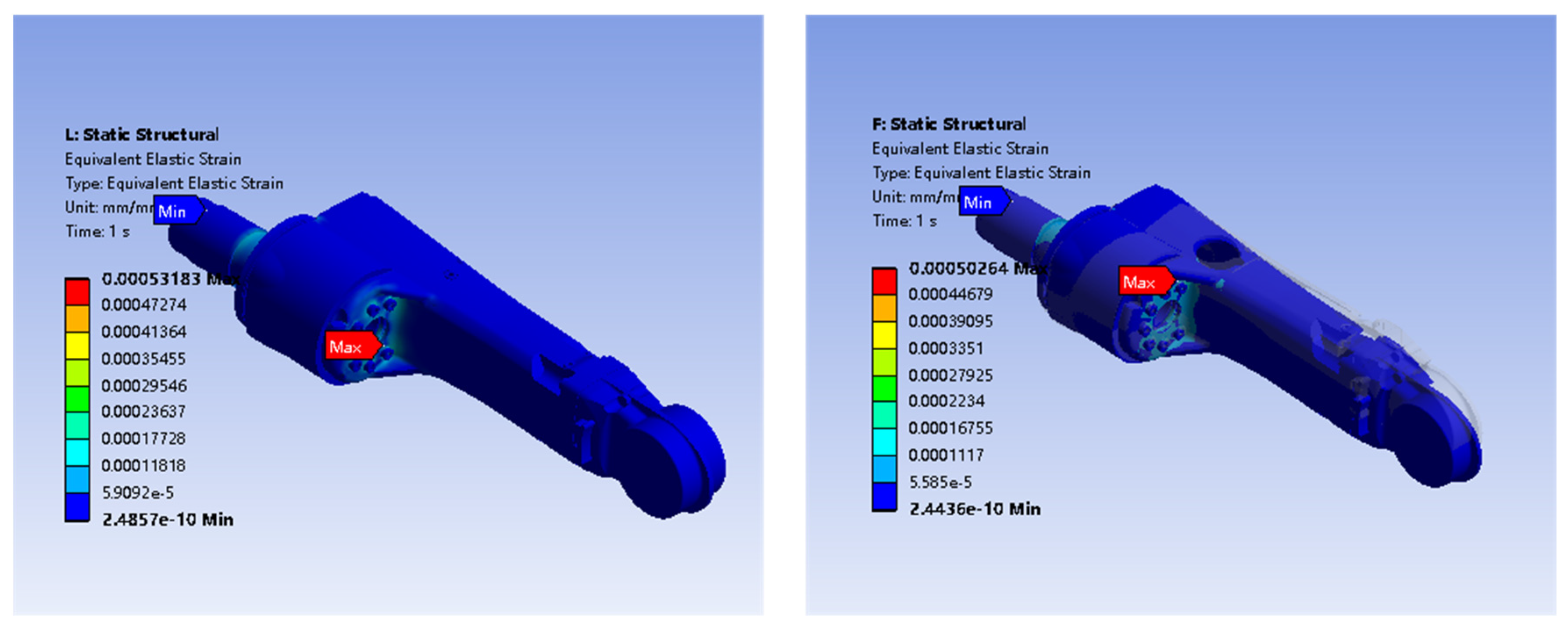
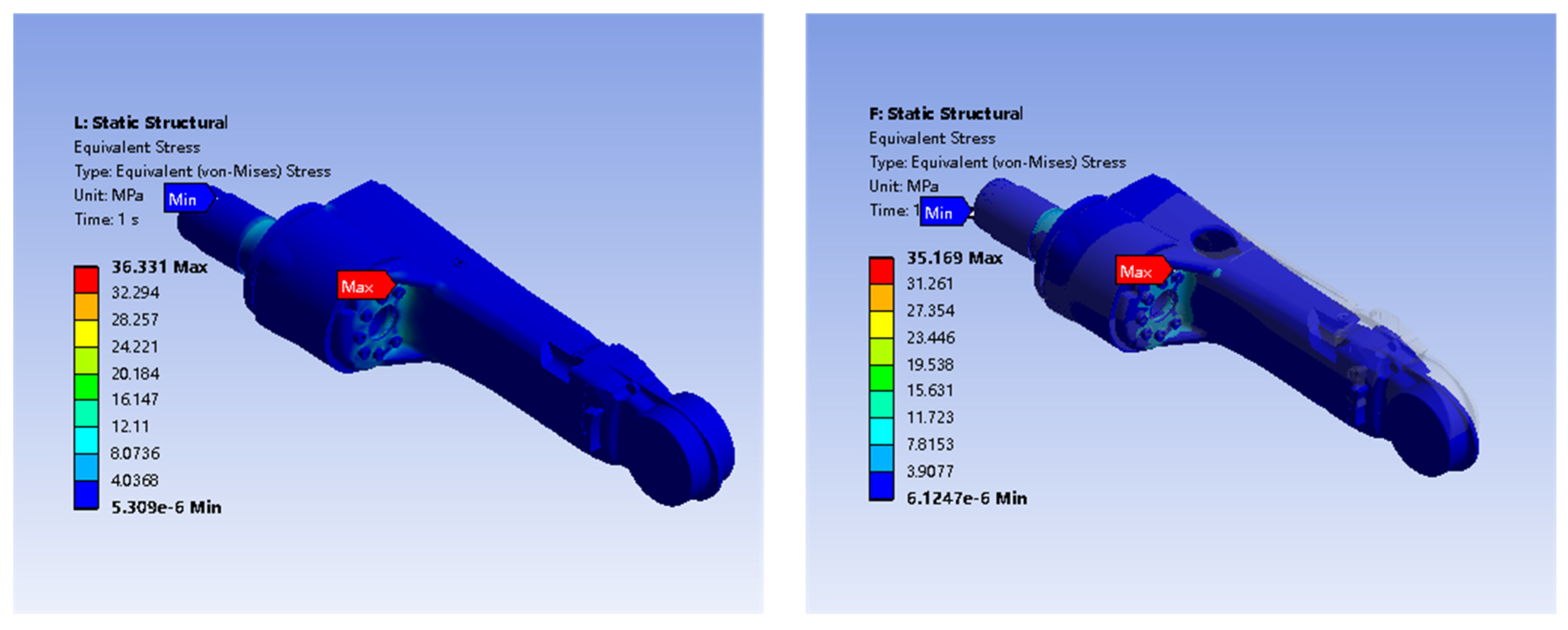
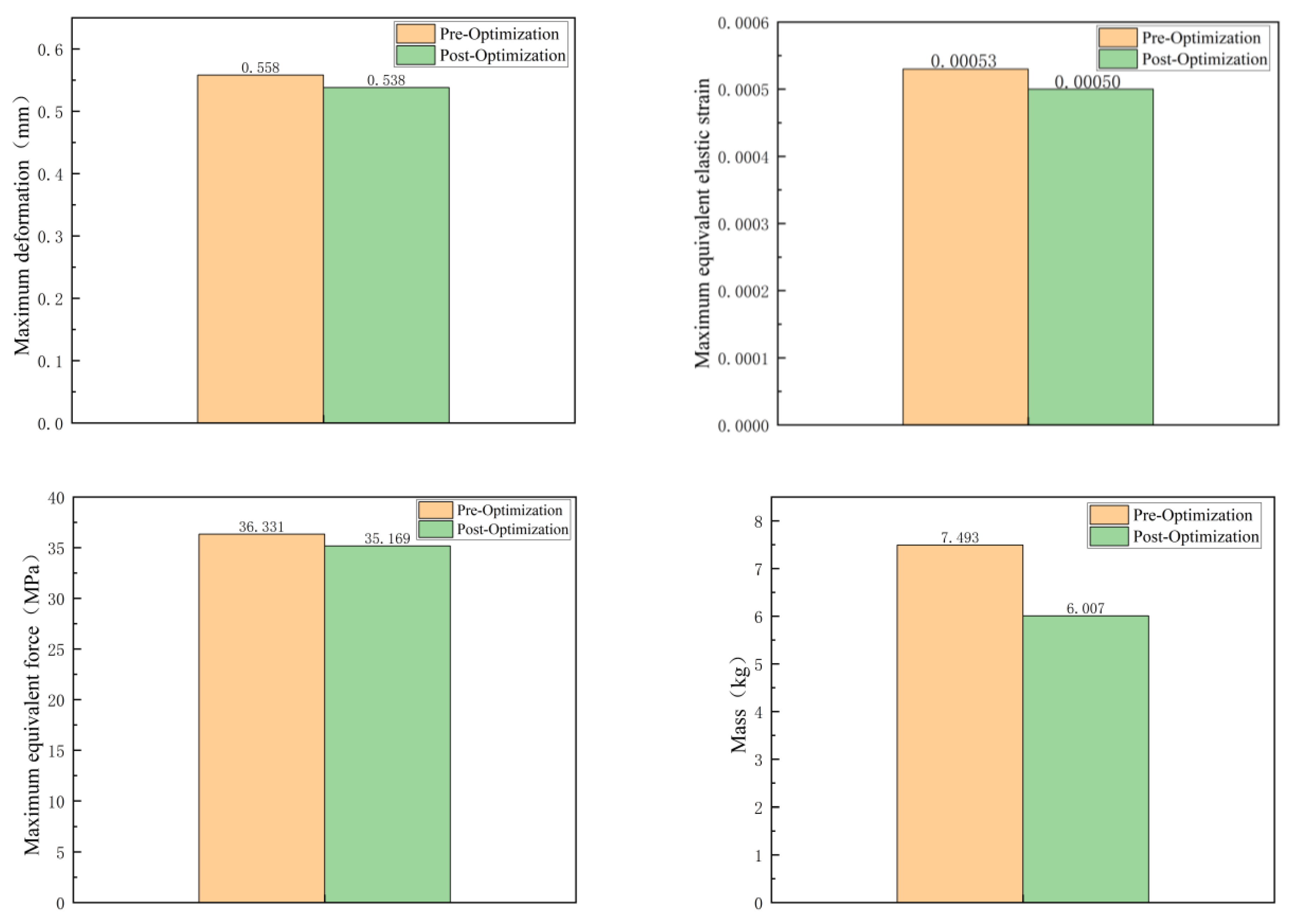
4.1. Static Analysis and Comparison

The loads and constraints applied to the forearm pre- and post-optimization of the welding robot are consistent in terms of magnitude and direction. The constraints and load directions are shown in Figure 4. According to the static condition of the welding robot, a vertical downward load of 150 N is applied at the end of the forearm, as shown at position A in Figure 4. Constraints are applied at the axis end of the welding robot forearm, as shown at position B in Figure 4. The standard Earth gravity direction is applied, as shown at position C in Figure 4. After setting the boundary conditions, meshing and static analysis simulations are conducted. The maximum total deformation of the forearm pre- and post-optimization is shown in Figure 5, the maximum equivalent elastic strain pre- and post-optimization is shown in Figure 6, and the maximum equivalent stress pre- and post-optimization is shown in Figure 7.
The comparison of deformation, stress, and strain in static analysis is shown in Figure 8. From the figure, it can be observed that the maximum total deformation at the end of the forearm pre-optimization is 0.558 mm, while post-optimization is reduced to 0.538 mm, resulting in a decrease of 3.6%. The maximum stress and strain are located at the connection between the forearm and the axis. The maximum stress pre-optimization is 36.331 MPa, and post-optimization is reduced to 35.169 MPa, resulting in a decrease of 3.2%. The maximum equivalent elastic strain pre-optimization is 0.00053, and post-optimization is reduced to 0.00050, which is a decrease of 5.7%.

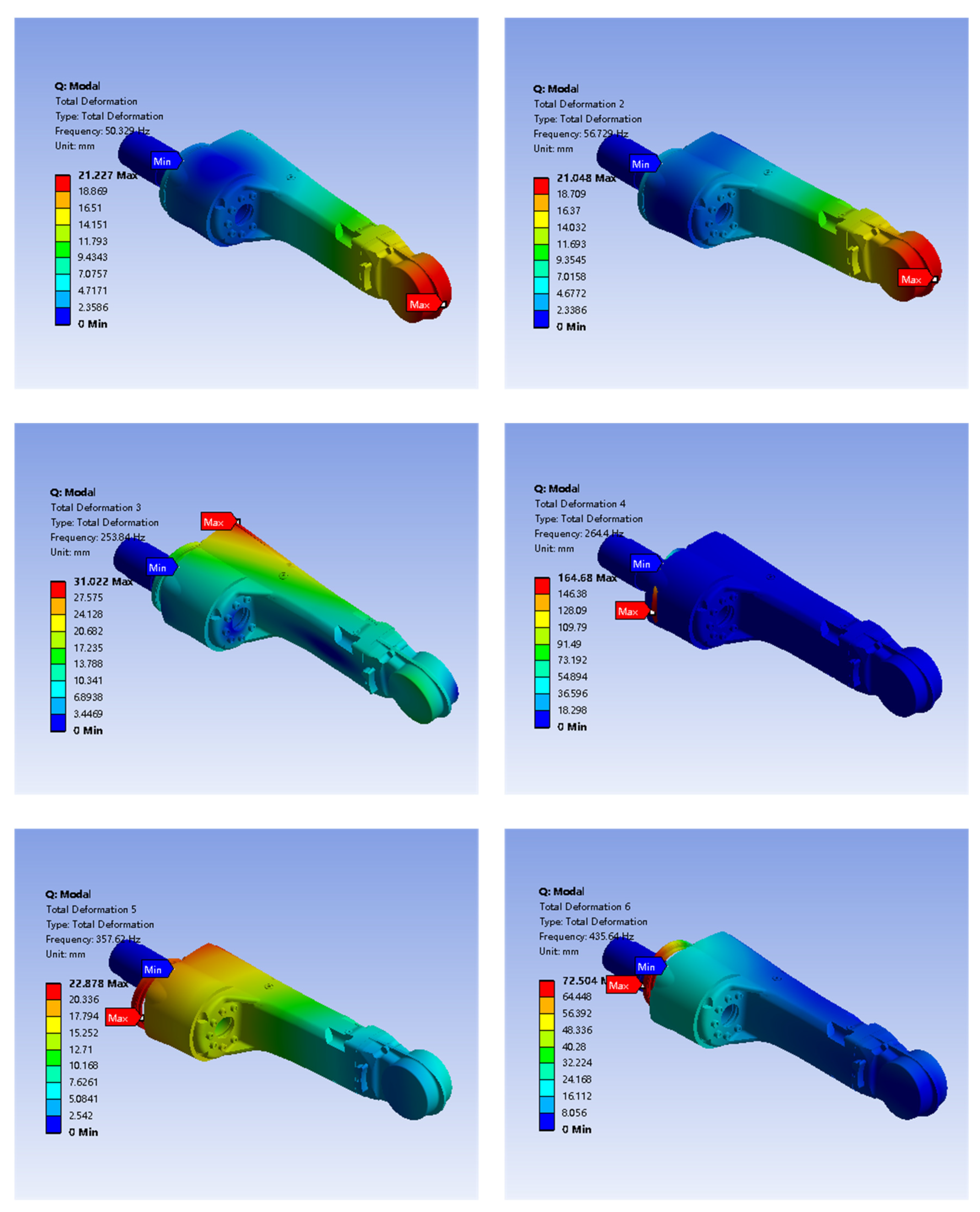
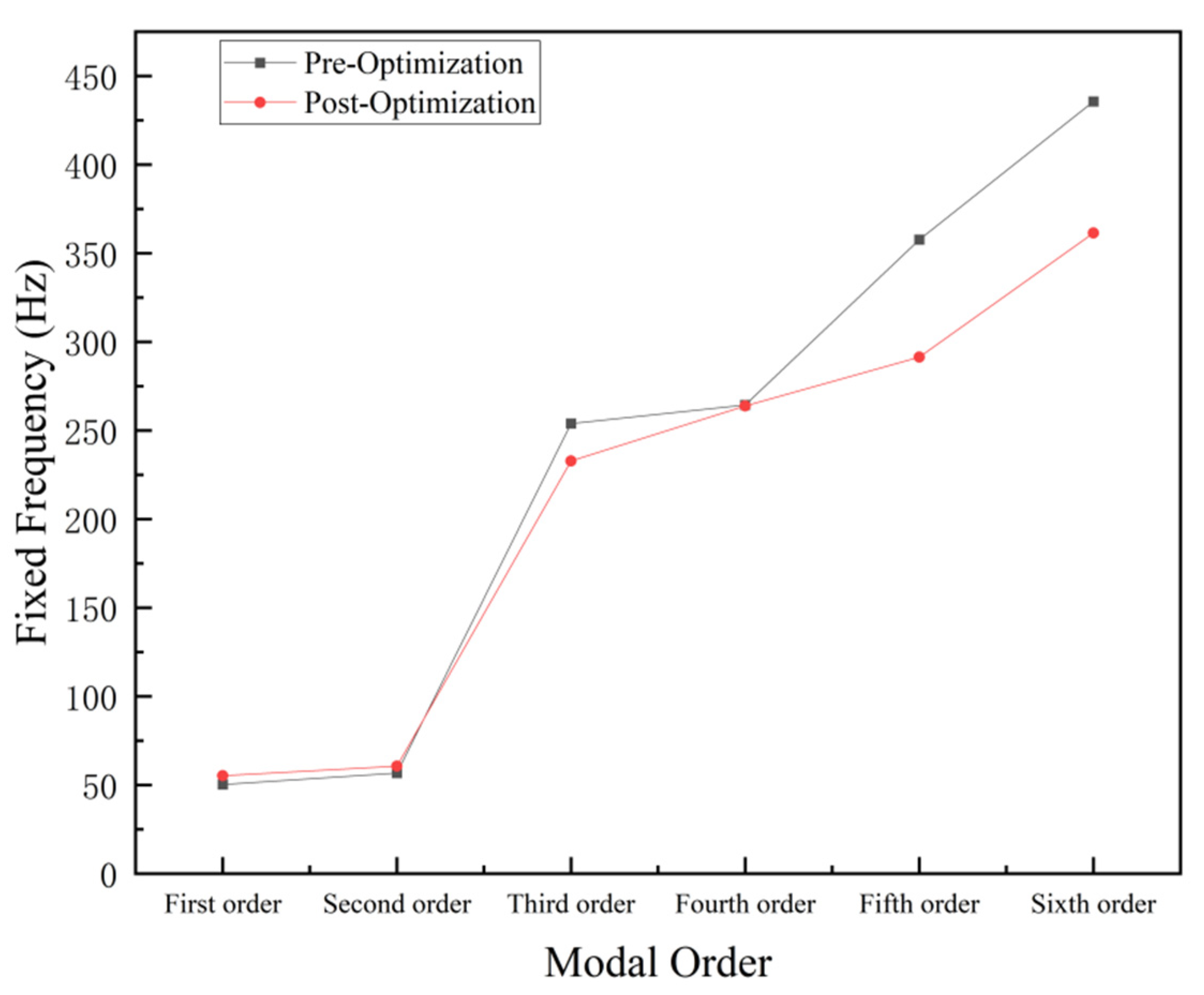
4.2. Modal Analysis Results Analysis

The natural frequencies and vibration modes of the welding robot forearm have a significant impact on the welding accuracy of the robot. The modal analysis of the forearm can provide insights into the dynamic characteristics of different modes and optimize the vibration response within different frequency ranges. Generally, the vibration frequencies of welding robots are relatively low, and resonance mainly occurs in the first and second modes [20]. To avoid resonance phenomena during the low-frequency operation of the forearm, it is crucial to increase the natural frequencies of the forearm in the lower modes.
As shown in Figure 9 below, the first six orders of modal deformation diagrams of the welding robot forearm before optimization are shown. Before performing modal analysis on the optimized welding robot forearm, the boundary conditions are set to the same as the pre-optimization modal analysis. Modal analysis is conducted to obtain the modal results of the optimized forearm and compare them with the pre-optimization results. Table 3 shows the first six mode natural frequencies of the welding robot forearm pre- and post-optimization, and they are plotted in a line graph for comparison, as shown in Figure 10.
Through the comparative analysis, it can be observed that the natural frequencies of the first and second modes of the welding robot forearm significantly increase post-structural topology optimization, resulting in improved modal responses. Generally, the lower the mode, the more significant the response and the more important it is. Therefore, the increase in the natural frequencies of the lower modes can effectively avoid resonance phenomena during the operation of the welding robot forearm, thereby improving welding accuracy and enhancing the stability and performance of the robotic arm.

4.3. Transient Simulation Comparative Analysis

To analyze the effect of structural topology optimization on the vibration characteristics and stress–strain behavior of the forearm under transient conditions, transient simulation analysis is conducted. The changes in vibration frequency, vibration amplitude, and stress–strain behavior of the welding robot forearm pre- and post-optimization are further compared under maximum operating conditions.

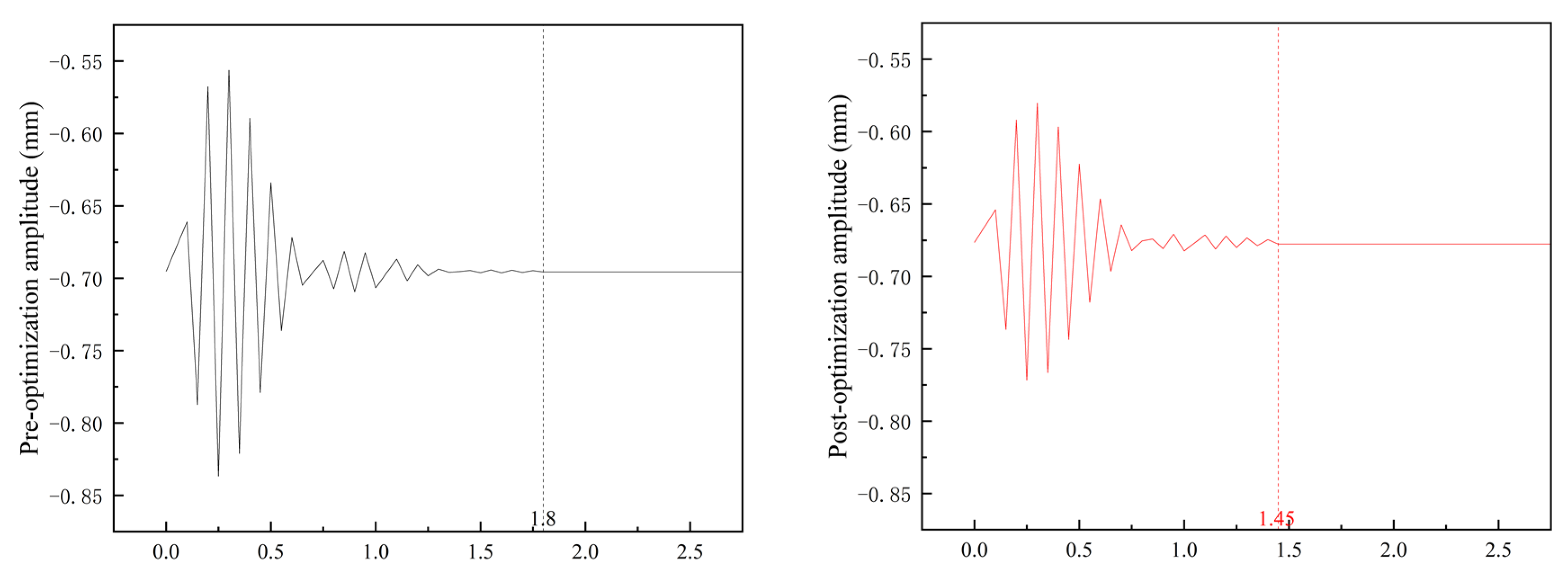
4.3.1. Comparison of Vibration Amplitude and Frequency

The forearm of the welding robot experiences vibrations due to the impact load from the welding actuator after it comes to a stop. Transient simulation is performed considering the maximum operating condition of the welding robot forearm, with a rotational speed of 60°/s. The comparison of vibration frequency and amplitude in the direction of motion pre- and post-optimization is shown in Figure 3, Figure 4, Figure 5, Figure 6, Figure 7, Figure 8, Figure 9, Figure 10 and Figure 11. It can be observed that the forearm of the welding robot continues to vibrate after coming to a stop under the maximum operating condition. The pre-optimized forearm reaches a stable state at around 1.8 s, while the optimized forearm reaches stability at around 1.45 s, indicating a 19.4% reduction in the vibration time post-optimization. Further analysis of the vibration amplitude shows that the maximum amplitude pre-optimization is 0.13 mm, while post-optimization is reduced to 0.095 mm, representing a 26.9% decrease in vibration amplitude. The transient simulation comparison demonstrates that structural topology optimization results in reduced vibration frequency and amplitude for the welding robot forearm.

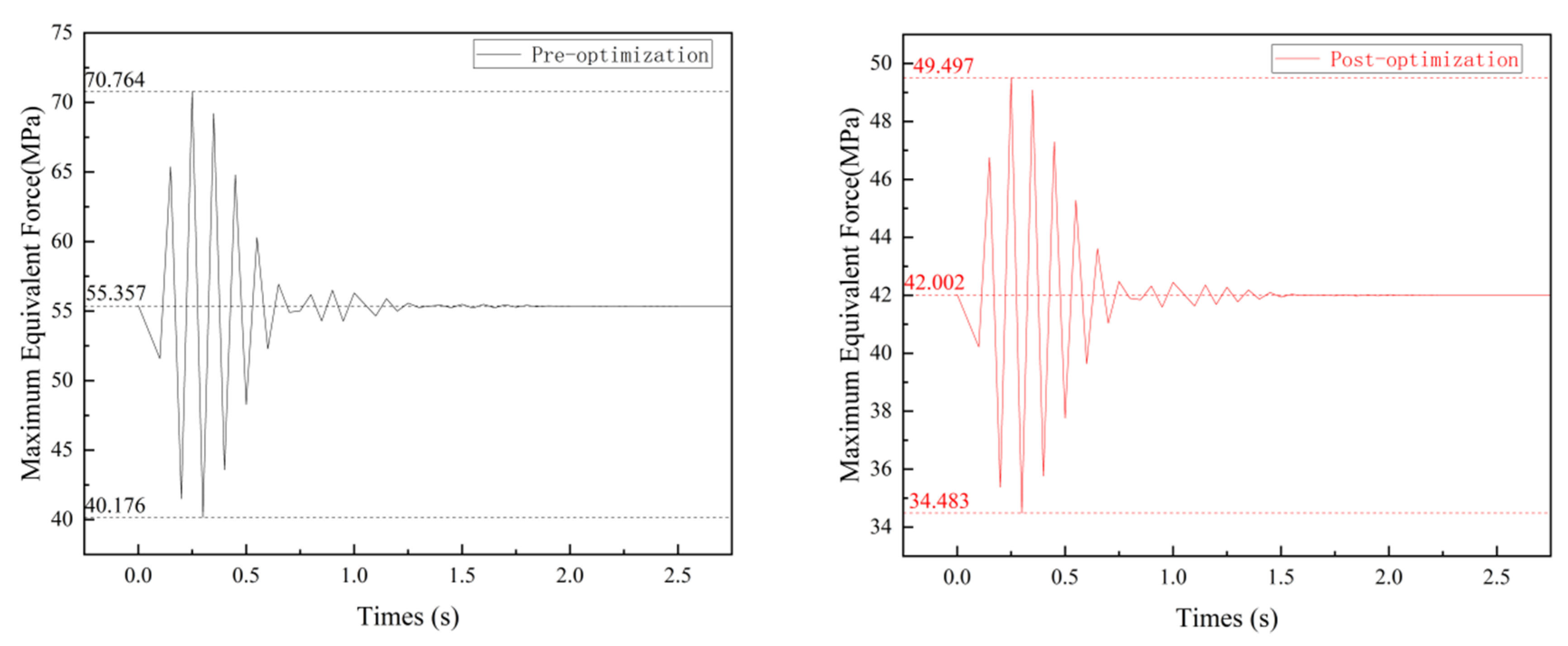
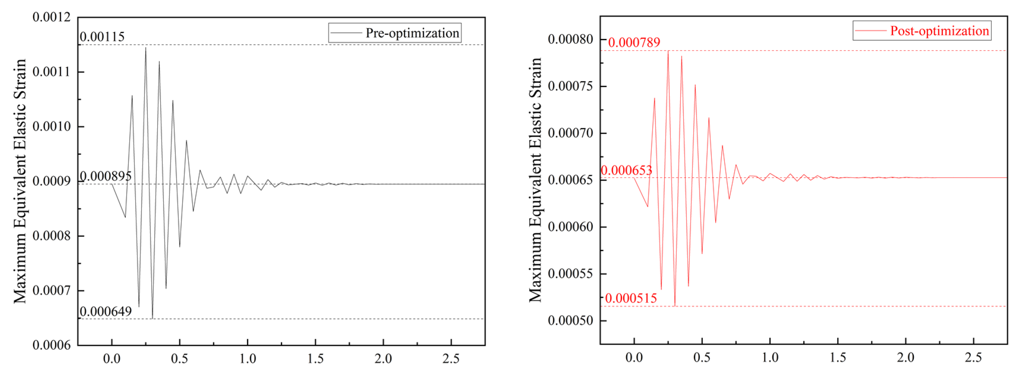
4.3.2. Comparison of Transient Stress and Strain

When the welding robot forearm rotates at a speed of 60°/s, the optimized forearm exhibits significantly reduced stress and strain variations resulting from vibrations, as shown in Figure 12 and Figure 13. The maximum amplitude of the maximum equivalent stress curve for the pre-optimized forearm is 15.3 MPa, while for the optimized forearm, it is reduced to 7.5 MPa, which is a decrease of 51.0%. After the vibration stabilizes, the maximum equivalent stress for the pre-optimized forearm is 55.357 MPa, while for the optimized forearm, it is reduced to 42.002 MPa, which is a decrease of 24.1%.
Similarly, when the welding robot forearm rotates at a speed of 60°/s, the transient strain amplitudes of the optimized forearm are significantly reduced. The maximum amplitude of the strain curve for the pre-optimized forearm is 0.00025, while for the optimized forearm, it is reduced to 0.000135, which is a decrease of 46%. After the vibration stabilizes, the maximum equivalent elastic strain for the pre-optimized forearm is 0.000895, while for the optimized forearm, it is reduced to 0.000653, resulting in a decrease of 27.0%. This indicates that structural topology optimization can effectively reduce the stress and strain of the forearm during high-speed motion, thereby improving the stability and safety of the mechanical structure.

5. Discussion

Based on the optimization and comparative simulation results mentioned above, the density-based structural topology optimization significantly reduces the weight of the welding robot forearm, enhancing its static and dynamic performances and effectively mitigating vibration effects. It is important to note that this study primarily utilized a single optimization method for the objective, and the objective selection was stringent. Future research could investigate alternative optimization methods like shape optimization, size optimization, or a combination of methods to compare and assess their efficacy in order to determine a more effective approach to lightweight forearm design.

6. Conclusions

To improve the production efficiency and working accuracy of the welding robot, a density-based method was employed to perform structural topology optimization of the forearm. Static, modal, and transient simulations were conducted to compare the performance of the pre-optimized and optimized models. The following conclusions were drawn:
(1)
The lightweight design of the welding robot forearm was achieved, resulting in a 19.8% reduction in mass and material savings, leading to cost reduction.
(2)
Through static simulation comparative analysis, it was observed that the mechanical performance of the optimized forearm was improved. The maximum total deformation decreased by 3.6%, the maximum stress decreased by 3.2%, and the maximum strain decreased by 5.7%. The mechanical performance of the optimized forearm exhibited better characteristics.
(3)
Modal simulation comparative analysis revealed that the natural frequencies of the optimized forearm increased, especially for the first and second modes, which showed significant improvements of 9.8% and 7.0%, respectively. This further reduced the possibility of resonance occurrence in the forearm.
(4)
Transient simulation comparative analysis demonstrated that the optimized forearm exhibited reduced vibration amplitudes and frequencies under maximum operating conditions, with a decrease of 19.4% and 26.9%, respectively. The maximum amplitudes of the equivalent stress and strain curves were reduced by 51.0% and 46%, respectively.
In conclusion, the structural topology optimization and lightweight design of the welding robot forearm improves its mechanical performance and vibration characteristics, which not only enhances its structural safety but also improves welding precision and stability, providing better assurance for the efficient operation of the welding robot.

Author Contributions

All authors participated in the conceptualization, H.P.: Methodology, Supervision, Writing—Original draft, Writing—Review and Editing, Data analysis, Data availability. Z.S.: Methodology, Writing—Original draft, Writing—Review and Editing, Software, Data curation, Data analysis. F.Y.: Methodology. J.H.: Supervision, Project administration, Funding acquisition. All authors have read and agreed to the published version of the manuscript.

Funding

This research was funded by Shandong Shui Po Intelligent Equipment Co., Ltd., Development of Welding Seam Tracking Vision System (B20340) and Jinan Nuoyi Laser Equipment Co., Ltd., Vibration Characterization of Robot Arm (B23480). and the National Natural Science Foundation (Grant No. 51979045).

Data Availability Statement

The data presented in this study are available in the main article.

Conflicts of Interest

The authors declared that they had no known competing financial interests or personal relationships that could have influenced the work reported in this paper, and that this work has no potential conflicts of interest with the companies acknowledged.

References

  1. Albu-Schäffer, A.; Haddadin, S.; Ott, C.; Stemmer, A.; Wimböck, T.; Hirzinger, G. The DLR Lightweight Robot: Design and Control Concepts for Robots in Human Environments. Ind. Robot Int. J. 2007, 34, 376–385. [Google Scholar] [CrossRef]
  2. Yin, H.; Liu, J.; Yang, F. Hybrid Structure Design of Lightweight Robotic Arms Based on Carbon Fiber Reinforced Plastic and Aluminum Alloy. IEEE Access 2019, 7, 64932–64945. [Google Scholar] [CrossRef]
  3. Gençer, G.M.; Öztoprak, N.; Akdağ, M.; Şen, H. Investigation of GFRP/AA7075-T6 Scarf Joint as a Robot Arm for High Natural Frequency and Damping Ratio. Arab. J. Sci. Eng. 2024, 49, 2027–2044. [Google Scholar] [CrossRef]
  4. Vogel, J.; Haddadin, S.; Simeral, J.D.; Stavisky, S.D.; Bacher, D.; Hochberg, L.R.; Donoghue, J.P.; van der Smagt, P. Continuous Control of the DLR Light-Weight Robot III by a Human with Tetraplegia Using the BrainGate2 Neural Interface System. In Experimental Robotics: The 12th International Symposium on Experimental Robotics, New Delhi and Agra, India, 18–21 December 2010; Khatib, O., Kumar, V., Sukhatme, G., Eds.; Springer: Berlin/Heidelberg, Germany, 2014; pp. 125–136. ISBN 978-3-642-28572-1. [Google Scholar]
  5. Zargham, S.; Ward, T.A.; Ramli, R.; Badruddin, I.A. Topology Optimization: A Review for Structural Designs under Vibration Problems. Struct. Multidisc. Optim. 2016, 53, 1157–1177. [Google Scholar] [CrossRef]
  6. Jia, J.; Sun, X. Structural Optimization Design of a Six-Degrees-of-Freedom Serial Robot with Integrated Topology and Dimensional Parameters. Sensors 2023, 23, 7183. [Google Scholar] [CrossRef]
  7. Yin, H.; Huang, S.; He, M.; Li, J. A Unified Design for Lightweight Robotic Arms Based on Unified Description of Structure and Drive Trains. Int. J. Adv. Robot. Syst. 2017, 14, 1729881417716383. [Google Scholar] [CrossRef]
  8. Liang, M.; Wang, B.; Yan, T. Dynamic Optimization of Robot Arm Based on Flexible Multi-Body Model. J. Mech. Sci. Technol. 2017, 31, 3747–3754. [Google Scholar] [CrossRef]
  9. Luo, H.; Fu, J.; Wang, P.; Liu, J.; Zhou, W. Design Optimization of the Ram Structure of Friction Stir Welding Robot. Mech. Adv. Mater. Struct. 2020, 27, 108–118. [Google Scholar] [CrossRef]
  10. Xue, H.; Yu, H.; Zhang, X.; Quan, Q. A Novel Method for Structural Lightweight Design with Topology Optimization. Energies 2021, 14, 4367. [Google Scholar] [CrossRef]
  11. Duddeck, F.; Hunkeler, S.; Lozano, P.; Wehrle, E.; Zeng, D. Topology Optimization for Crashworthiness of Thin-Walled Structures under Axial Impact Using Hybrid Cellular Automata. Struct. Multidisc. Optim. 2016, 54, 415–428. [Google Scholar] [CrossRef]
  12. Liu, Q.; Fan, G.; Tan, Z.; Li, Z.; Zhang, D.; Wang, J.; Zhang, H. Precipitation of Al3Zr by Two-Step Homogenization and Its Effect on the Recrystallization and Mechanical Property in 2195 Al–Cu–Li Alloys. Mater. Sci. Eng. A 2021, 821, 141637. [Google Scholar] [CrossRef]
  13. Xie, L.; Zhang, Y.; Ge, M.; Zhao, Y. Topology Optimization of Heat Sink Based on Variable Density Method. Energy Rep. 2022, 8, 718–726. [Google Scholar] [CrossRef]
  14. Zhang, J.; Chen, Y.; Zhai, J.; Hou, Z.; Han, Q. Topological Optimization Design on Constrained Layer Damping Treatment for Vibration Suppression of Aircraft Panel via Improved Evolutionary Structural Optimization. Aerosp. Sci. Technol. 2021, 112, 106619. [Google Scholar] [CrossRef]
  15. Xia, Q.; Shi, T. Generalized Hole Nucleation through BESO for the Level Set Based Topology Optimization of Multi-Material Structures. Comput. Methods Appl. Mech. Eng. 2019, 355, 216–233. [Google Scholar] [CrossRef]
  16. Xue, R.; Liu, C.; Zhang, W.; Zhu, Y.; Tang, S.; Du, Z.; Guo, X. Explicit Structural Topology Optimization under Finite Deformation via Moving Morphable Void (MMV) Approach. Comput. Methods Appl. Mech. Eng. 2019, 344, 798–818. [Google Scholar] [CrossRef]
  17. Xu, S.; Liu, J.; Zou, B.; Li, Q.; Ma, Y. Stress Constrained Multi-Material Topology Optimization with the Ordered SIMP Method. Comput. Methods Appl. Mech. Eng. 2021, 373, 113453. [Google Scholar] [CrossRef]
  18. Rojas-Labanda, S.; Sigmund, O.; Stolpe, M. A Short Numerical Study on the Optimization Methods Influence on Topology Optimization. Struct. Multidisc. Optim. 2017, 56, 1603–1612. [Google Scholar] [CrossRef]
  19. Wan, C.; Jiao, H.; Lv, L.; Lu, C. Multi-Material Topology Optimization Based on Multiple Simp of Variable Density Method. J. Mech. Sci. Technol. 2024, 38, 749–759. [Google Scholar] [CrossRef]
  20. Yao, P.; Zhou, K.; Lin, Y.; Tang, Y. Light-Weight Topological Optimization for Upper Arm of an Industrial Welding Robot. Metals 2019, 9, 1020. [Google Scholar] [CrossRef]
Figure 1. General structure of the welding robot.
Actuators 13 00209 g001
Figure 2. Topological density distribution.
Actuators 13 00209 g002
Figure 3. Structural model of forearm after reconstruction.
Actuators 13 00209 g003
Figure 4. Constraints and loads pre- and post-optimization.
Actuators 13 00209 g004
Figure 5. Maximum total deformation diagram pre- and post-optimization.
Actuators 13 00209 g005
Figure 6. Maximum equivalent force diagram pre- and post-optimization.
Actuators 13 00209 g006
Figure 7. Maximum equivalent force diagram pre- and post-optimization.
Actuators 13 00209 g007
Figure 8. Comparison of static analysis of the forearm.
Actuators 13 00209 g008
Figure 9. Natural frequencies of the first 6 modes of the forearm.
Actuators 13 00209 g009
Figure 10. Comparison of the sixth-order modal natural frequency of the forearm pre- and post-optimization.
Actuators 13 00209 g010
Figure 11. Amplitude curve pre- and post-optimization.
Actuators 13 00209 g011
Figure 12. Stress curve pre- and post-optimization.
Actuators 13 00209 g012
Figure 13. Strain curve pre- and post-optimization.
Actuators 13 00209 g013
Table 1. Geometric dimensions of forearm.
Geometric Dimensions
Length in X direction (mm)727.39
Length in Y direction (mm)258.69
Length in Z direction (mm)274.28
Volume (m3)0.0027
Table 2. Characteristics of forearm materials.
Ai5083 Material Characteristics
Density (kg/m3)2800
Young’s Modulus (MPa)70,300
Poisson’s Ratio0.33
Tensile Yield strength (MPa)230
Compressive Yield strength (MPa)230
Tensile Ultimate strength (MPa)320
Mass (kg)7.493
Table 3. Comparison of modes pre- and post-optimization of the forearm of the welding robot.
Modal OrderFrequency Pre-Optimization (Hz)Frequency Post-Optimization (Hz)
First order50.32955.267
Second order56.72960.678
Third order253.84232.86
Fourth order264.4263.84
Five order357.62291.38
Six order435.64361.45
Disclaimer/Publisher’s Note: The statements, opinions and data contained in all publications are solely those of the individual author(s) and contributor(s) and not of MDPI and/or the editor(s). MDPI and/or the editor(s) disclaim responsibility for any injury to people or property resulting from any ideas, methods, instructions or products referred to in the content.

