Abstract
Intelligent robots are often used to explore various areas instead of humans. However, when the driving joint is damaged, the actuated robot degenerates to an underactuated robot, and the traditional control method is not suitable for the underactuated robot. In this work, a two-stage control approach for a planar prismatic–rotational (PR) underactuated robot is introduced. Firstly, we establish the dynamic model and describe the underactuated constraint between an underactuated rotational joint and active prismatic joint. Secondly, the trajectory with multiple parameters is planned to ensure that the two joints reach the target position. Based on underactuated constraints and the evaluation function, the differential evolution algorithm (DEA) is used to optimize these parameters. After that, in stage 1, we design the controller to move the active prismatic joint to the desired position. Meanwhile, the underactuated rotational joint is rotating freely. In stage 2, we design the controller for the active prismatic joint to track the planned trajectory. By means of this strategy, both joints reach their target locations simultaneously. The final simulation result demonstrates that this strategy is effective.
1. Introduction
In recent years, with the rapid development of artificial intelligence [1], machine learning [2], sensor technology [3], machine vision and automation technology [4], robots are widely used in many walks of life, including industrial manufacturing [5], medical care [6], home services [7], agriculture [8] and logistics storage [9]. Usually, most of these robots are fully driven, but when one of the controllers is damaged, the actuated robots will become underactuated robots [10]. At this time, the actuated control strategy is no longer applicable. If the control strategy is not adjusted in time, the robot that is out of control in the working state will have great security risks.
Underactuated robots have been an important research object in intelligent robot and nonlinear control theory for nearly century [11]. Such robots have the typical characteristics of the underactuated system that the number of actuators is less than the number of degrees of freedom to be controlled [12,13,14]. Aircraft [15], bionic instruments [16], pendulums [17] and inverted pendulums [18] are mature underactuated systems that have been widely used in daily life and have created enormous value for human beings. The underactuated robot has fewer independent actuators, and this not only makes the structure more compact, but also reduces the total mass and energy consumption [19,20,21]. The underactuated robot still has many advantages that are worthy of indepth exploration and development by scholars in various fields.
With the application of intelligent robots in the unexplored fields of deep sea and space, the efficiency and safety of exploration have been greatly improved [22]. In order to practice the concept of green development and low-carbon environmental protection, underactuated robots have seen increasing applications. Wang et al. [23] proposed a stable control strategy for a vertical underactuated manipulator. As an important branch of underactuated robots [24,25], the horizontal planar underactuated robot disregards effects of gravity, and all of the reachable places are balancing positions [26]. Nevertheless, the complex nonlinear characteristics make it difficult to design a continuous controller for a planar manipulator [27]. The above factors undoubtedly greatly increase the difficulty of control [28,29]. Michele [30] used the Laplace transform method to control the motion of planar underactuated robots, and the influence of friction is considered. The differential flatness characteristics of underactuated planar open-chain robots are studied in [31]. Ref. [32] proposed a motion planning method for planar underactuated robots. For the planar underactuated robot with an underactuated last joint, a trajectory planning control method is proposed in [33].
Different structures of the planar underactuated robot determine different dynamic coupling characteristics [34,35,36]. The PR underactuated robot is a special robot composed of an active prismatic link and underactuated rotational link, which has strong randomness and instability [37]. Wu et al. [38] derived a new control equation of the underactuated link for the PR underactuated robot to achieve position control. Huang et al. [39] designed an iterative control approach such that the PR underactuated robot would quickly reach the appointed position exponentially. Ichida et al. [40] used the Hespanha–Morse switching technique to realize stable control of the PPR underactuated robot. Luca et al. [41] exploited the recursive property of the dynamic system to design the dynamic feedback linearization law, and used the polynomial interpolation method to plan the smooth motion trajectory for the planar PPRn underactuated robot. Moreover, the development of the model degradation method provides a new control idea for simplifying the complex planar PnR underactuated robot into the simplest planar PR underactuated robot [42,43].
Most of the above position control strategies do not make full use of the underactuated constraint, which makes the design complicated. Therefore, we propose a two-stage control method that combines tracking control with motion planning. Firstly, the coupling constraint relationships between the two links are analyzed based on the dynamic model. Secondly, to ensure the robot can reach the goal point smoothly, a trajectory with several customizable parameters is developed. The parameters are calculated using the DEA based on the underactuated coupling characteristics of the robot. Next, the prismatic link is driven to the desired position by designing a PD controller, while the rotational link is rotating freely due to the lack of a controller. Then, the active joint is driven by a second controller to track the trajectory. The underactuated link is indirectly regulated to the target position because of the coupling relationship. The final simulation result demonstrates that this strategy is effective.
2. Preparations
This section mainly includes the establishment of the dynamic model, the derivation of the underactuated coupling relationship and the description of the control strategy.
2.1. Dynamic Model
For this paper, the function of the dynamic model is to establish the relationship between input torque and output states of the joints.
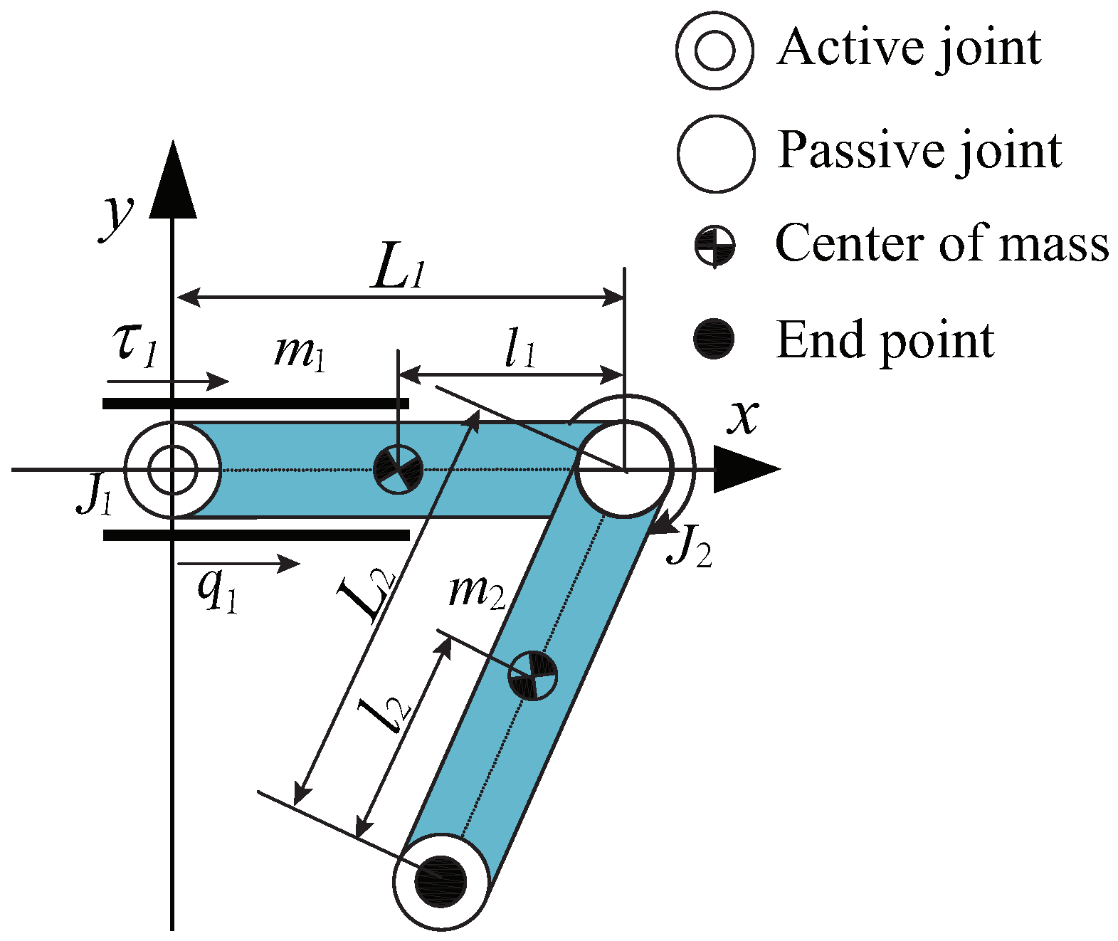
According to Figure 1, the planar PR underactuated robot consists of an active prismatic joint and a rotational joint. The control torque of robot joints is , where is applied on the active prismatic link, and the control torque of the underactuated rotational link is 0 N·m. The meaning of the parameters of the planar PR robot is shown in Table 1.

Figure 1.
The physical model of the planar PR robot.

Table 1.
The meaning of parameters.
The dynamic model is as follows:
where = is a two-dimensional vector representing positions of two links. Similarly, the angular acceleration and angular velocity are denoted, respectively, by and , respectively. is the inertia matrix, and the centrifugal and coriolis forces are included in , their specific expression in [39].
2.2. Underactuated Constraints
For the un-actuated joint, because of its lack of a controller, we cannot directly control it to complete the expected task. Therefore, according to the coupling characteristics between an un-actuated joint and actuated joint, we indirectly control the un-actuated joint by controlling the actuated joint. The establishment of underactuated constraints describes the coupling characteristics of the un-actuated joint and actuated joint.
The underactuated part in (1) is
According to (2), the underactuated coupling constraints between active and underactuated links are described as follow.
where is the initial angle and is the angular velocity of the underactuated rotational link.
2.3. Control Strategy
The underactuated characteristics of the system make its control more complicated, so we design a two-stage control strategy to achieve the control goal. The following is the concrete implementation process of the two-stage control method.
Stage 1: the active prismatic link is driven to the desired position by designing a PD controller, while the rotational link is rotating freely due to the lack of a controller.
Stage 2: for the active prismatic link, an oscillation trajectory with several parameters is developed, and the DEA is used to optimize the parameters. Motion planning is carried out according to the final state of the un-actuated joint in the first stage and its target state. The second controller is designed to drive the prismatic link to track the trajectory. Finally, the underactuated rotational link arrives at the appointed position under the underactuated constraint relation.
3. Motion Planning
The core idea of the motion planning method is to dynamically plan the motion state of the driving link by using the underactuated constraint relationship, so as to control the underactuated link. In this section, we fully consider the initial state, control target and underactuated characteristic of the underactuated robot to design the oscillatory trajectory, , for the active prismatic link.
where represents the target angle of the first link, and and are the amplitude values.
where is the connection time of two sech(·) functions, respectively, and is the terminal time when the robot realizes the control objective.
The first and second derivatives of are
When , the active prismatic link reaches , and the free rotation state of the underactuated rotational link is caused by the uncontrollable drift characteristic due to the nonholonomic constraints.
The trajectory of the driving joint is roughly composed of target angle and two hyperbolic secant functions. This trajectory reciprocates around , and the initial and final speeds are both zero, which meet the control goal of the driving joint. In the optimization process, the amplitude parameters and of the two hyperbolic secant functions of the trajectory are opposite. Due to the underactuated constraint, the underactuated link obtains opposite speeds in two time periods, which is beneficial to stabilize it to the target angle. In order to make the underactuated link converge to the target state accurately, it is necessary to calculate the undetermined parameters of the trajectory.
and are undetermined trajectory parameters, which determine different dynamic trajectories. Meanwhile, we find that the state of the underactuated rotational link is determined by different trajectories. Therefore, we select appropriate trajectory parameters of with the DEA. Trajectories with different parameters will eventually lead to different un-actuated joint states, which are compared with the target states as evaluation indexes.
The evaluation function is
The optimization process is described as follows:
- ①
- Randomly generating an initialized population, while the initial parameters are expressed as , , and .
- ②
- ③
- If , , , and , where is small enough. Otherwise, the program is to ④.
- ④
- The parameters are mutated, crossed and selected, then update , , and . Back to②.
At last, we obtain a feasible optimized trajectory with appropriate parameters , , and . The active prismatic link tracks the optimized trajectory, and the underactuated rotational link indirectly moves under the coupling constraints between the two links.
4. Controller Design
4.1. The First Controller Design
The state space equation is:
where
Based on the control objective, we construct the Lyapunov function as follows
The derivative is
To ensure , the first controller is constructed as
where . Since is a positive-definite symmetric matrix and , the controller, , is non-singular.
The invariant set is defined as:
where is a small positive constant.
Defining sets as:
Let be the maximum invariant set in , then , , .
When , then and
Substituting into , we obtain
According to LaSalle’s principle [44], the first controller realizes the control objective of the active prismatic link if the following conditions are met.
where and are sufficiently small positive constants.
4.2. The Second Controller Design
In stage 2, we design the second controller to track the designed trajectory. First, we construct the Lyapunov function as
and the derivative is
To ensure that , we construct the second controller as
The above equation can meet the following conditions:
when , .
According to LaSalle’s principle, the prismatic link converges to the state again, while the underactuated rotational link reaches its target states when .
5. Simulation
In this section, MATLAB/Simulink is used for simulation experiments to build the control system, and three groups of simulations are designed to test the control method. The main part of the simulation experiment system includes the dynamic model, two-stage controller and trajectory planning. The simulation flow of the two-stage control strategy is as follows:
- ①
- Use the first stage controller to drive the first joint to the target position, and record the angle and angular velocity of the second joint at this time as and .
- ②
- Taking and as the initial states of the second passive joint and combining with the target state, trajectory planning is carried out. The second stage controller is used to drive the first joint to move along the planned trajectory.
The basic parameters are shown in Table 2. The parameters of two controllers (13) and (21) are chosen as . The parameters of the DEA are .
Table 2.
The structure parameters.
5.1. Case 1
In this case, we set the initial and final states of the system to carry out simulation experiments to prove the effectiveness of the two-stage control strategy. The initial value and target value are chosen to be
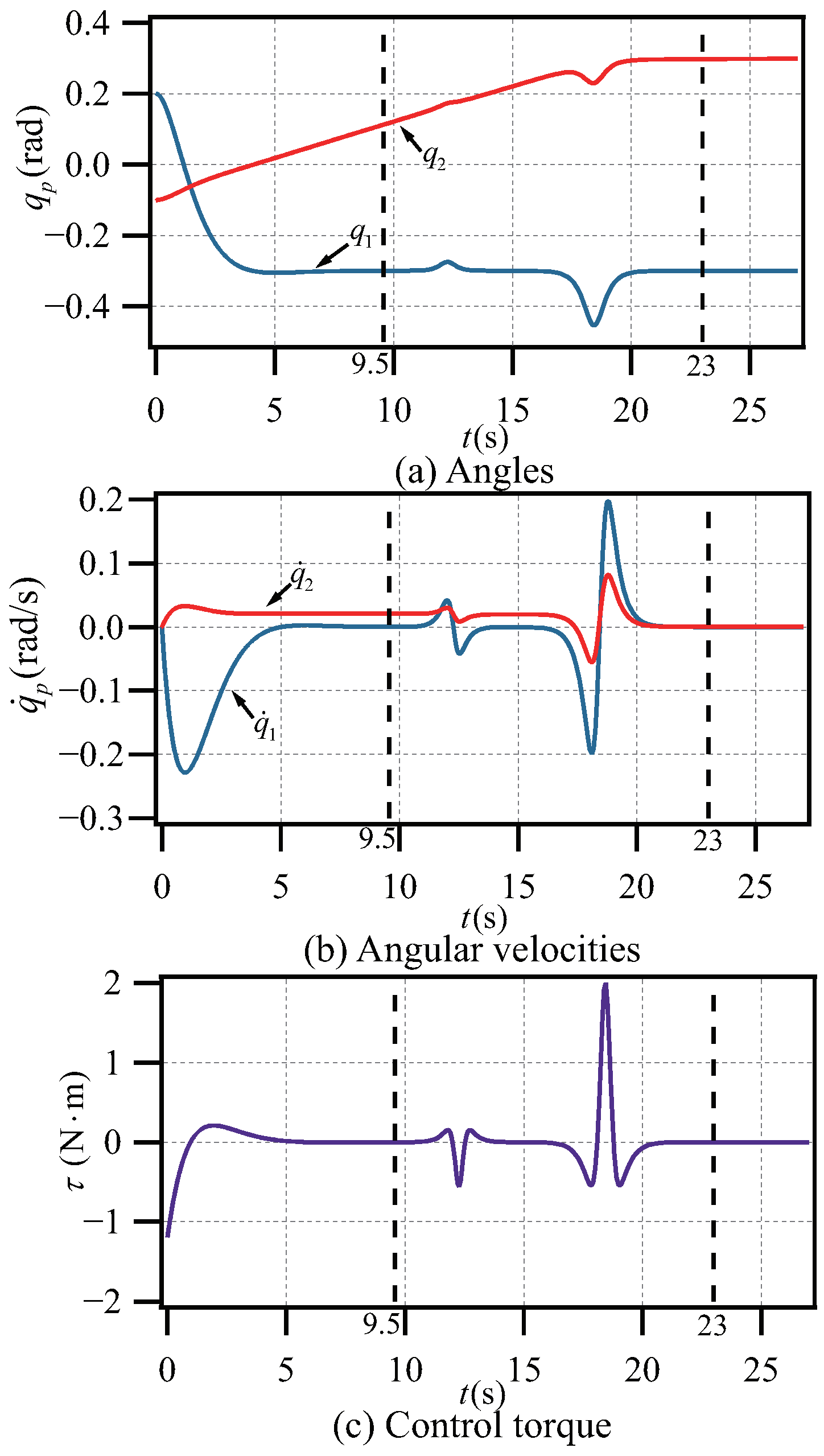
From the simulation results (Figure 2a,b), the first stage is s. At this stage, under the action of the first controller, the active prismatic link reaches the target state for the first time at 9.5 s, and the underactuated rotational link moves uncontrollably to the state . In the second stage, using the DEA to plan the trajectory, the active prismatic link tracks the designed trajectory to converge to the target state again at 23 s, and the underactuated rotational link also converges to the target state smoothly. In Figure 2c, the control torque of the active prismatic joint in stage 1 does not exceed N·m, and in stage 2 does not exceed 2 N·m.
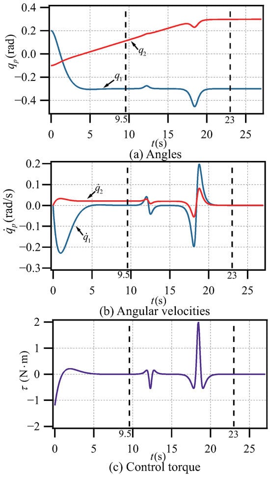
Figure 2.
Simulation result of Case 1.
From the simulation results, the two-stage control strategy is feasible. Next, we design several groups of comparative simulations, selecting the same simulation parameters as those in reference [39] and verifying the superiority through the simulation results.
5.2. Case 2
In Case 2, we compare our method with the strategy that combines the nilpotent approximation with the iterative control method in [39] to verify the superiority. For this reason, we select the same system model, initial conditions and control objectives as those in [39]. The states are chosen as
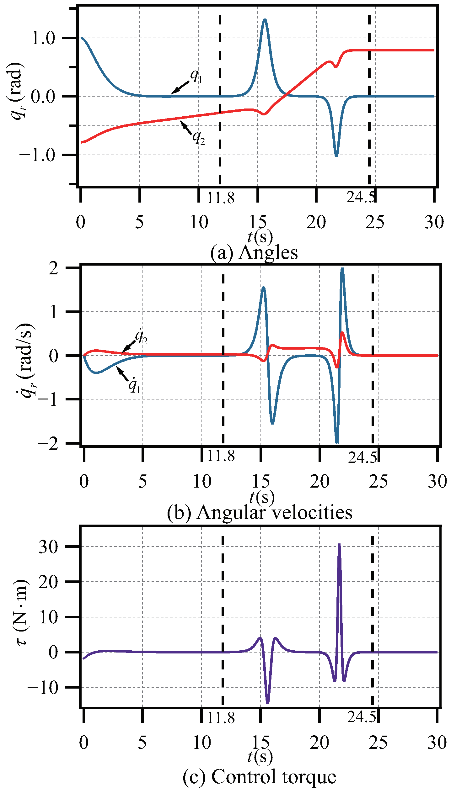
Figure 3 shows the simulation result of Case 2, where Figure 3a,b represent the position and speed of two joints, respectively, and Figure 3c represents the driving torque of the first joint. By analyzing Figure 3, the prismatic link reaches the appointed state for the first time at 11.8 s. Then, the active prismatic link tracks the designed trajectory to return to the appointed state again at 24.5 s, and the underactuated rotational link also reaches the target state smoothly.

Figure 3.
Simulation result of Case 2.
In reference [39], the underactuated rotational link is not required to meet any conditions before the start of stage 2, and the control flow is more complicated. Compared with the results in [39], our control method has more advantages, as follows:
- (1)
- Our method does not require the underactuated rotational link to meet any conditions before the start of stage 2, which greatly simplifies the control difficulty.
- (2)
- Our method can control the system to the target position in 15 s, but the method in [39] needs 38 s. This means that our method can achieve the control goal more quickly.
- (3)
- Our control process is smoother and more feasible. It can be seen from Figure 3c that the control force of the first joint will not change frequently when using our control method. But in the simulation result of [39], this torque changes sharply frequently, which is very unfavorable to the controller.
- (4)
- It is worth mentioning that we fully utilize the underactuated coupling constraint relationship, instead of complex coordinate transformation calculations.
5.3. Case 3
In order to eliminate contingency and further prove the universality of our method advantages, we design another group of simulations in Case 3.
In this case, we choose a different target point, considering the periodicity. The states of the system are selected to be the same as in [39], which is convenient for comparison of control effects. The states are chosen to be
where k is an integer.
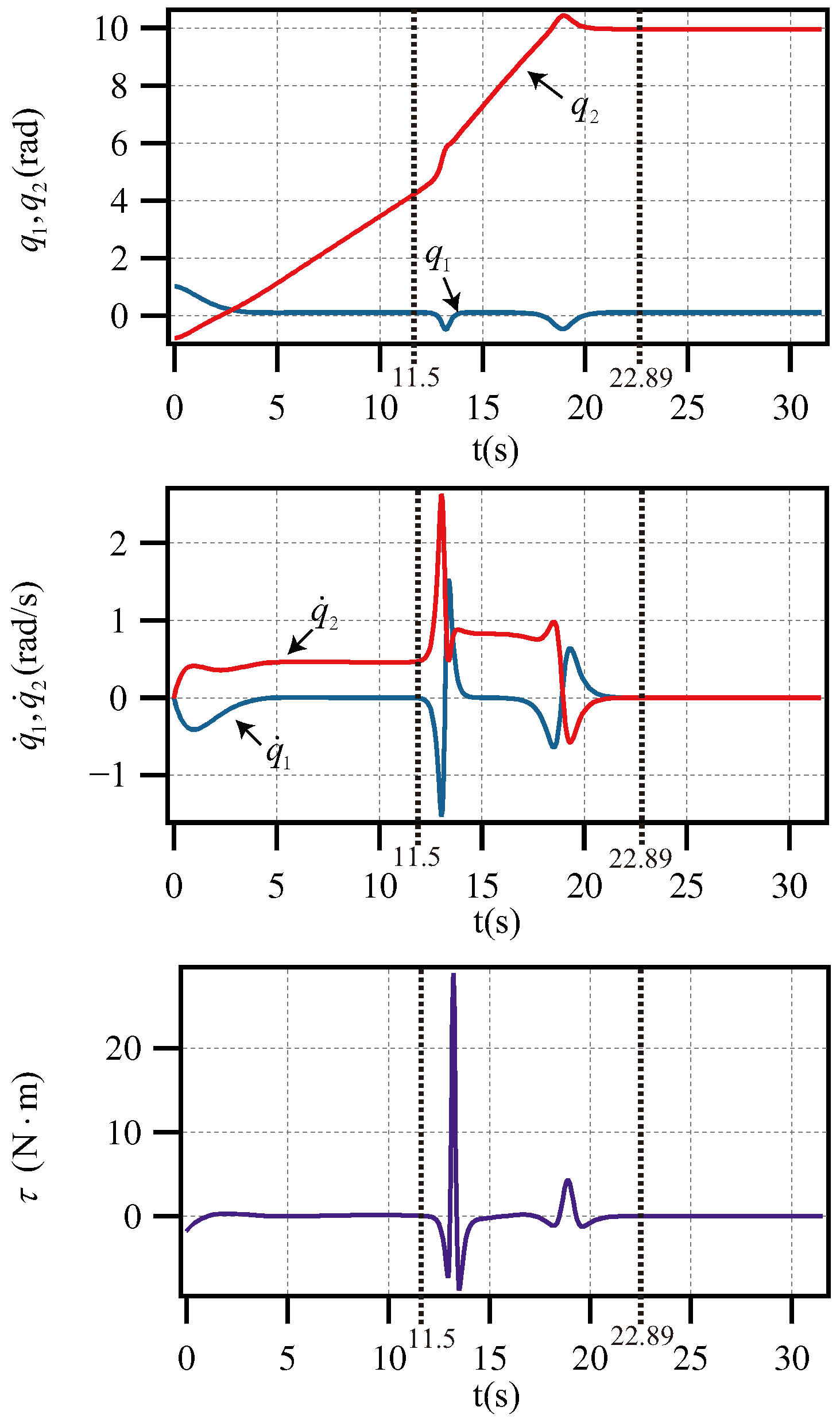
From the simulation results (Figure 4), the active prismatic link reaches the target state for the first time at 11.5 s. At this time, the underactuated link swings to 4.1395 rad freely. In the next stage, the prismatic link follows the designed trajectory to move back to the target position again at 22.89 s, and the underactuated rotational link also converges to the target state smoothly. Finally, the underactuated rotational link converges to 19/6, where k = 1 in Equation (25). Compared with the control method in [39], the underactuated rotational link is not required to meet any conditions before the start of the stage 2, and the control process is faster. It is noteworthy that we make full use of the inherent coupling constraint, thereby eliminating the need for intricate coordinate transformation calculations. This proves that our method is universal.
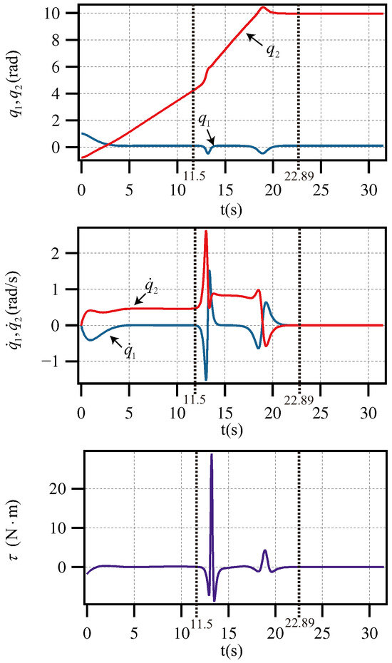
Figure 4.
Simulation result of Case 3.
Therefore, from the whole simulation section, we can draw the conclusion that our proposed two-stage control method can solve the control problem of planar PR robots. And by comparing with [39], it is proved that our method is innovative and superior.
6. Conclusions
We present a control method with two stages based on the physical configuration and underactuated constraints for the underactuated PR robot. The detailed work is as follows:
- (1)
- The dynamic model of the planar PR underactuated robot is established and the underactuated coupling relationships are derived.
- (2)
- In stage 1, the active prismatic link is intended to be driven by the PD controller in order to attain the desired position. In stage 2, the active prismatic link tracks the designed oscillation trajectory to the target position under the action of the designed tracking controller, and the underactuated rotational link indirectly converges to the target state during this process.
- (3)
- The simulation results demonstrate this control strategy’s viability and superiority for planar PR underactuated robots.
Author Contributions
Conceptualization, D.L. and Z.H.; methodology, D.L.; software, D.L. and Z.W.; validation, Z.H.; formal analysis, D.L.; investigation, Z.W.; resources, Z.H.; data curation, Z.W.; writing—original draft preparation, D.L. and Z.W.; writing—review and editing, Z.H.; visualization, D.L. and Z.W.; supervision, Z.H.; project administration, Z.H.; funding acquisition, Z.H. All authors have read and agreed to the published version of the manuscript.
Funding
This work was supported in part by Hubei Province Nature Science Foundation under Grant 2023AFB380, in part by Hubei Key Laboratory of Digital Textile Equipment (Wuhan Textile University) under Grant KDTL2022003, and in part by Hubei Key Laboratory of Intelligent Robot (Wuhan Institute of Technology) under Grant HBIRL202301.
Institutional Review Board Statement
Not applicable.
Informed Consent Statement
Not applicable.
Data Availability Statement
The data presented in this study are available on request from the corresponding author.
Conflicts of Interest
The authors declare no conflicts of interest.
References
- Korteling, J.E.; van de Boer-Visschedijk, G.C.; Blankendaal, R.A.M.; Boonekamp, R.C.; Eikelboom, A.R. Human-versus artificial intelligence. Front. Artif. Intell. 2021, 4, 622364. [Google Scholar] [CrossRef] [PubMed]
- Lee, K.M.; Yoo, J.; Kim, S.W.; Lee, J.H.; Hong, J. Autonomic machine learning platform. Int. J. Inf. Manag. 2019, 49, 491–501. [Google Scholar] [CrossRef]
- Rashid, R.; Zhang, E.; Abdi, A. On the Performance of a New Wireless Communication Compact Multichannel Underwater Receiver Using a Sphere Vector Sensor. IEEE Trans. Veh. Technol. 2023, 73, 1458–1461. [Google Scholar] [CrossRef]
- Hu, B.; Wang, Y.; Orlik, P.V.; Koike-Akino, T.; Guo, J. Co-design of safe and efficient networked control systems in factory automation with state-dependent wireless fading channels. Automatica 2019, 105, 334–346. [Google Scholar] [CrossRef]
- Mukherjee, D.; Gupta, K.; Chang, L.H.; Najjaran, H. A survey of robot learning strategies for human-robot collaboration in industrial settings. Robot. Comput. Manuf. 2022, 73, 102231. [Google Scholar] [CrossRef]
- Frennert, S.; Aminoff, H.; Östlund, B. Technological frames and care robots in eldercare. Int. J. Soc. Robot. 2021, 13, 311–325. [Google Scholar] [CrossRef]
- Gonzalez-Aguirre, J.A.; Osorio-Oliveros, R.; Rodríguez-Hernández, K.L.; Lizárraga-Iturralde, J.; Menendez, R.M.; Ramírez-Mendoza, R.A.; Ramírez-Moreno, M.A.; Lozoya-Santos, J.d.J. Service robots: Trends and technology. Appl. Sci. 2021, 11, 10702. [Google Scholar] [CrossRef]
- Chakraborty, S.; Elangovan, D.; Govindarajan, P.L.; Elnaggar, M.F.; Alrashed, M.M.; Kamel, S. A comprehensive review of path planning for agricultural ground robots. Sustainability 2022, 14, 9156. [Google Scholar] [CrossRef]
- Liu, H.; Zhou, L.; Zhao, J.; Wang, F.; Yang, J.; Liang, K.; Li, Z. Deep-learning-based accurate identification of warehouse goods for robot picking operations. Sustainability 2022, 14, 7781. [Google Scholar] [CrossRef]
- Khanmirza, E.; Daneshjou, K.; Ravandi, A.K. Underactuated flexible aerial manipulators: A new framework for optimal trajectory planning under constraints induced by complex dynamics. J. Intell. Robot. Syst. 2018, 92, 599–613. [Google Scholar] [CrossRef]
- Chen, X.L.; Zhao, H.; Sun, H.; Zhen, S.C.; Mamun, A.A. Optimal adaptive robust control based on cooperative game theory for a class of fuzzy underactuated mechanical systems. IEEE Trans. Cybern. 2022, 52, 3632–3644. [Google Scholar] [CrossRef] [PubMed]
- Gutiérrez-Giles, A.; Ruggiero, F.; Lippiello, V.; Siciliano, B. Nonprehensile manipulation of an underactuated mechanical system with second-order nonholonomic constraints: The robotic hula-hoop. IEEE Robot. Autom. Lett. 2018, 3, 1136–1143. [Google Scholar] [CrossRef]
- Lai, X.Z.; Wang, Y.W.; Wu, M.; Cao, W.H. Stable control strategy for planar three-link underactuated mechanical system. IEEE ASME Trans. Mechatron. 2016, 21, 1345–1356. [Google Scholar] [CrossRef]
- Wang, L.J.; Lai, X.Z.; Meng, Q.X.; Wu, M. Effective control method based on trajectory optimization for three-link vertical underactuated manipulators with only one active joint. IEEE Trans. Cybern. 2023, 53, 3782–3793. [Google Scholar] [CrossRef] [PubMed]
- Wang, F.; Gao, H.M.; Wang, K.; Zhou, C.; Zong, Q.; Hua, C.C. Disturbance observer-based finite-time control design for a quadrotor UAV with external disturbance. IEEE Trans. Aerosp. Electron. Syst. 2021, 57, 834–847. [Google Scholar] [CrossRef]
- Huang, Z.X.; Li, X.P.; Wang, J.R.; Zhang, Y.; Mei, J.F. Human pulse detection by a soft tactile actuator. Sensors 2022, 22, 5047. [Google Scholar] [CrossRef] [PubMed]
- Massaro, M.; Lovato, S.; Limebeer, D.J.N. The optimal erection of the inverted pendulum. Appl. Sci. 2022, 12, 8112. [Google Scholar] [CrossRef]
- Du, D.J.; Zhang, C.D.; Song, Y.H.; Zhou, H.Y.; Fei, M.R.; Li, W.P. Real-time H control of networked inverted pendulum visual servo systems. IEEE Trans. Cybern. 2020, 50, 5113–5126. [Google Scholar] [CrossRef]
- Gritli, H.; Belghith, S. LMI-based synthesis of a robust saturated controller for an underactuated mechanical system subject to motion constraints. IEEE Trans. Syst. Man Cybern. Syst. 2021, 51, 7663–7674. [Google Scholar] [CrossRef]
- Sun, H.; Yang, L.W.; Chen, Y.H.; Zhao, H. Constraint-based control design for uncertain underactuated mechanical system: Leakage-type adaptation mechanism. Eur. J. Control 2021, 57, 179–193. [Google Scholar] [CrossRef]
- Emran, B.J.; Najjaran, H. A review of quadrotor: An underactuated mechanical system. Annu. Rev. Control 2018, 46, 165–180. [Google Scholar] [CrossRef]
- Hu, J.Y.; Niu, H.L.; Carrasco, J.; Lennox, B.; Arvin, F. Voronoi-based multi-robot autonomous exploration in unknown environments via deep reinforcement learning. IEEE Veh. Technol. Mag. 2020, 69, 14413–14423. [Google Scholar] [CrossRef]
- Wang, L.; Lai, X.; Zhang, P.; Wu, M. A control strategy based on trajectory planning and optimization for two-link underactuated manipulators in vertical plane. IEEE Trans. Syst. Man, Cybern. Syst. 2021, 52, 3466–3475. [Google Scholar] [CrossRef]
- Liu, D.; Lai, X.Z.; Wang, Y.W.; Wan, X.B.; Wu, M. Position control for planar four-link underactuated manipulator with a passive third joint. ISA Trans. 2019, 87, 46–54. [Google Scholar] [CrossRef] [PubMed]
- Chen, S.Y.; Wang, Y.W.; Zhang, P.; Su, C.Y. Continuous control strategy of planar 3-Linkage underactuated manipulator based on broad neural network. Actuators 2021, 10, 249. [Google Scholar] [CrossRef]
- Wang, Y.W.; Yang, H.Q.; Zhang, P. Iterative convergence control method for planar underactuated manipulator based on support vector regression model. Nonlinear Dyn. 2020, 102, 2711–2724. [Google Scholar] [CrossRef]
- Huang, Z.X.; Wang, L.J. Review of control method of planar underactuated mechanical system. J. Wuhan Inst. Technol. 2021, 43, 448–454. [Google Scholar]
- Huang, Z.X.; Wei, S.Q.; Hou, M.Y.; Wang, L.J. Finite-time control strategy for swarm planar underactuated robots via motion planning and intelligent algorithm. Mears. Control 2022, 56, 813–819. [Google Scholar] [CrossRef]
- Xiong, P.Y.; Lai, X.Z.; Wu, M. A stable control for second-order nonholonomic planar underactuated mechanical system: Energy attenuation approach. Int. J. Control 2018, 91, 1630–1639. [Google Scholar] [CrossRef]
- Tonan, M.; Doria, A.; Bottin, M.; Rosati, G. Oscillation-free point-to-point motions of planar differentially flat under-actuated robots: A Laplace transform method. Robotica 2024, 42, 1262–1280. [Google Scholar] [CrossRef]
- Agrawal, S.K.; Sangwan, V. Design of under-actuated open-chain planar robots for repetitive cyclic motions. In Proceedings of the International Design Engineering Technical Conferences and Computers and Information in Engineering Conference, Philadelphia, PA, USA, 10–13 September 2006; Volume 42568, pp. 1057–1066. [Google Scholar]
- Tonan, M.; Bottin, M.; Doria, A.; Rosati, G. Motion planning of differentially flat planar underactuated robots. Robotics 2024, 13, 57. [Google Scholar] [CrossRef]
- Luca, A.D.; Oriolo, G. Trajectory planning and control for planar robots with passive last joint. Int. J. Robot. Res. 2002, 21, 575–590. [Google Scholar] [CrossRef]
- Urrea, C.; Kern, J.; Alvarez, E. Design of a generalized dynamic model and a trajectory control and position strategy for n-link underactuated revolute planar robots. Control Eng. Pract. 2022, 128, 105316. [Google Scholar] [CrossRef]
- Wu, J.D.; She, J.H.; Wang, Y.W.; Chun, C.Y. Position and posture control of planar four-Link underactuated manipulator based on neural network model. IEEE Trans. Ind. Electron. 2020, 67, 4721–4728. [Google Scholar] [CrossRef]
- Huang, Z.X.; Hou, M.Y.; Wei, S.Q.; Wang, L.J. The unified control strategy for planar Acrobot and Pendubot. J. Shenzhen Univ. Sci. Eng. 2023, 40, 275–283. [Google Scholar] [CrossRef]
- Alaci, S.; Ciornei, F.C.; Suciu, C.C.; Romanu, I.C. The effect of structural aspect for planar systems with 2DOF upon the stability of motion. In IOP Conference Series: Materials Science and Engineering; IOP Publishing: Bristol, UK, 2021; p. 012003. [Google Scholar]
- Wu, L.C.; Xinkai, K.; Yang, G.S. Nonholonomic control of a planar Prismatic-Revolute under-actuated manipulator. In Proceedings of the 2013 Science and Information Conference, London, UK, 7–9 October 2013; pp. 144–147. [Google Scholar]
- Huang, Z.X.; Wei, S.Q.; Chen, Z.; Wang, L.J. Iterative contraction stability control strategy for planar prismatic-rotational underactuated robot. IEEE Access 2023, 11, 55947–55953. [Google Scholar] [CrossRef]
- Ichida, K.; Watanabe, K.; Izumi, K. Control of three-link underactuated manipulators by a logic-based switching method. In Proceedings of the International Conference on Networking, Sensing and Control, Okayama, Japan, 26–29 March 2009; pp. 108–112. [Google Scholar]
- Luca, A.D.; Iannitti, S. Smooth trajectory planning for XYnR planar underactuated robots. In Proceedings of the IEEE/RSJ International Conference on Intelligent Robots and Systems, Lausanne, Switzerland, 30 September–4 October 2002; pp. 1651–1656. [Google Scholar]
- Li, J.; Wang, L.J.; Chen, Z.; Huang, Z.X. Drift suppression control based on online intelligent optimization for planar underactuated manipulator with passive middle joint. IEEE Access 2021, 9, 38611–38619. [Google Scholar] [CrossRef]
- Huang, Z.X.; Lai, X.Z.; Zhang, P.; Wang, Y.W.; Wu, M. Virtual model reduction based control strategy of planar three-link underactuated manipulator with middle passive joint. Int. J. Control Autom. Syst. 2020, 19, 29–39. [Google Scholar] [CrossRef]
- LaSalle, J.P. Stability theory for ordinary differential equations. J. Differ. Equ. 1968, 4, 57–65. [Google Scholar] [CrossRef]
Disclaimer/Publisher’s Note: The statements, opinions and data contained in all publications are solely those of the individual author(s) and contributor(s) and not of MDPI and/or the editor(s). MDPI and/or the editor(s) disclaim responsibility for any injury to people or property resulting from any ideas, methods, instructions or products referred to in the content. |
© 2024 by the authors. Licensee MDPI, Basel, Switzerland. This article is an open access article distributed under the terms and conditions of the Creative Commons Attribution (CC BY) license (https://creativecommons.org/licenses/by/4.0/).