Article

Double Air Chambers Pneumatic Artificial Muscle and Non-Hysteresis Position Control

1
Department of Intelligent Mechatronics, Faculty of Systems Science and Technology, Akita Prefectural University, Yurihonjo 015-0055, Japan
2
Department of Mechanical Science and Engineering, Faculty of Science and Technology, Hirosaki University, Hirosaki 036-8224, Japan
3
Program of Artificial Intelligence and Mechanical Engineering, School of Engineering, Kwansei Gakuin University, Sanda 669-1330, Japan
*
Author to whom correspondence should be addressed.
Actuators 2024, 13(8), 282; https://doi.org/10.3390/act13080282 (registering DOI)
Submission received: 12 June 2024 / Revised: 23 July 2024 / Accepted: 25 July 2024 / Published: 26 July 2024
(This article belongs to the Special Issue Advanced Technologies in Soft Pneumatic Actuators)

Abstract

:
In this paper, we propose a double air chambers artificial muscle to eliminate the hysteresis in the extension and contraction movement of pneumatic artificial muscles. In this paper, the basic structure of the double air chambers artificial muscle is a rubberless artificial muscle with a particularly large hysteresis loop. The double air chambers artificial muscle aims to eliminate hysteresis by directly pressurizing the inside and outside of the air chamber and actively deforming the air chamber. The hysteresis is reduced by the pressure outside of the air chamber (external pressure). Since the appropriate external pressure varies depending on the contraction force and amount of contraction, we proposed a method to regulate the appropriate external pressure by feedback control. The experimental results show that hysteresis was eliminated in the static characteristics. It was also found that the output gain decreased, and the phase lag increased as the target frequency increased. The output gain did not change with increasing load. The phase lag tended to improve with the PID controller compared to the PI controller. These results suggest that the combination of double air chambers artificial muscle and external pressure-regulated feedback control can achieve non-hysteresis position control, and it is useful as an actuator in mechatronic systems.

1. Introduction

In recent years, machines that include automatic controls, such as robots that coexist with humans [1,2,3,4] and wearable robotics [5,6,7,8,9,10], have come to operate in environments that are close to or involve contact with humans. In such environments, human safety is a top priority, and softness and lightness in terms of hardware, such as mechanical structures and actuators, are important.
In this background, various pneumatic soft actuators have been developed [11,12,13]. Pneumatics soft actuators are mostly composed of silicon rubber, and various behaviors are created by combining the shape of the air chamber and the materials that constrain the deformation of the rubber. It can be fabricated by molding silicone rubber, and in recent years, a direct three-dimensional fabricating by a 3D printer has also been proposed. Ling shows many examples of various printable soft actuators [14], and Gul shows how to manufacture them [15]. Lee introduces Tensegrity, a printable and flexible deformable structure [16].
Pneumatic artificial muscle (PAM) is one of those pneumatic soft actuators. Although pneumatic artificial muscles with various characteristics have been proposed according to differences in deformation constraints, etc., they are mainly classified into the McKibben-type rubber artificial muscle [17,18,19,20,21] and the axial fiber-reinforced rubber artificial muscle called the Warsaw-type [22,23,24,25,26]. For McKibben-type artificial muscles, Chou [17] described the basic characteristics and output model in detail. Tondu also summarized many findings on pneumatic artificial muscles, including an improvement of the static model [18,19], and application to a robot arm with antagonistic drive [20,21]. For the Warsaw-type, static models have been studied [22,26], and detailed analyses of actuator deformation have been conducted using FEM [24] or mathematical expression [25]. In addition, evaluations of durability have been reported [23]. Among these, Saito et al. proposed the rubber-less artificial muscle (RLAM) [27]. It is similar to McKibben-type rubber artificial muscle, but the air chamber is an airbag made of non-stretchable material instead of a rubber tube, and it can generate a large contraction force at low pressure. As with other PAMs, static model [28], durability evaluation [29], and joint control of a robot arm with an antagonistic drive system [28,30] are reported. A similar Warsaw-type model, the Pleated Pneumatic Muscle (PPM), has been presented by Daerden [31,32]. PPM has pleats that increase the amount of contraction by increasing the deformation during inflation. These pneumatic artificial muscles are lightweight and passively soft due to the compressibility of air and are expected to be used as actuators for robots that cooperate with humans and wearable robots.
However, almost all pneumatic artificial muscles have hysteresis in extension and contraction movements. In the McKibben and Warsaw types of artificial muscles, which use rubber material as an air chamber and the type of contracting by increasing an internal pressure, the air chamber expands when internal pressure is increasing, generating an axial contraction force due to the pantograph mechanism of the net sleeve or axial fiber constraint, and PAMs contract. When the internal pressure is reduced, the rubber air chamber returns to its original shape, radial contraction and axial extension occurs simultaneously, then the PAMs extend. In PAMs with rubber air chambers, previous studies have reported that the hysteresis is not negligible. In the case of the McKibben-type artificial muscle, the major factor is the friction between the net sleeve and the rubber air chamber [17,20], in the case of Warsaw-type artificial muscle, the major factor is the non-linear viscoelastic properties of the rubber [24,33].
In addition to the above, the RLAM has a very large hysteresis loop [34]. This is because the air chamber of the RLAM is made of a non-stretchable material, so the air chamber does not deform with decreasing the internal pressure. The RLAM requires external force not only to balance the internal pressure but also to deform the air chamber, which is thought to make it difficult to perform extension movements. In any case, hysteresis characteristics degrade control performance and make it difficult to obtain sufficient positioning accuracy.
Therefore, we propose a double air chambers pneumatic artificial muscle (W-PAM) that considers hysteresis reduction using two pressure systems around the air chamber. W-PAM is an artificial muscle with two air chambers. Similarly, several ideas for artificial muscles with two air chambers have been reported. Al-Fahaam proposed the extensor–contractor pneumatic artificial muscle (ECPAM) [35]. The structure of that is extrapolating an extension-type McKibben muscle to a contraction-type McKibben muscle, and it can generate force in both contraction and extension. Hassan proposed a double-acting McKibben-type artificial muscle that switches the direction of motion between contraction and extension by mechanically changing the initial angle of the mesh of the net sleeve and by inflating the inner air chamber [36]. Zheng proposed a DA-sleeve muscle [37], a double-acting artificial muscle that is active in two directions, contraction and extension, by inserting a tubular component in the center of the air chamber of a McKibben-type artificial muscle that contracts under pressure. These are intended to generate force in two directions, contraction and extension, and are important proposals in terms of improving the functionality of pneumatic artificial muscles, but these have not been verified to resolve the hysteresis characteristic.
In this paper, the basic structure and operational principle of the W-PAM are described, and the basic extension and contraction characteristic and hysteresis characteristic are evaluated. Then, applying position feedback control by operating one side pressure that is proposed in this study, we indicate the possibility of reducing hysteresis of the W-PAM. And the usefulness of this method is also discussed by adding an evaluation of the frequency characteristics for application as an actuator in mechatronics system.

2. Double Air Chambers Pneumatic Artificial Muscle

2.1. Rubber-Less Artificial Muscle

First, we describe the RLAM, which is the basis of the W-PAM proposed in this study. The RLAM replaces the rubber tube as an air chamber of a general McKibben-type artificial muscle with an airbag of non-stretchable material. The driving principle is the same as that of the McKibben-type artificial muscle. The air chamber is inserted inside a mesh sleeve and they are not bonded to each other. Therefore, when the air chamber is pressurized to expand the sleeve from the inside, the mesh sleeve slides across the surface of the air chamber, generating force and displacement in the direction of contraction using deformation by the pantograph mechanism. Compared to McKibben-type artificial muscle, RLAM can generate a greater contraction force at lower pressure because the air chamber is more easily inflated.

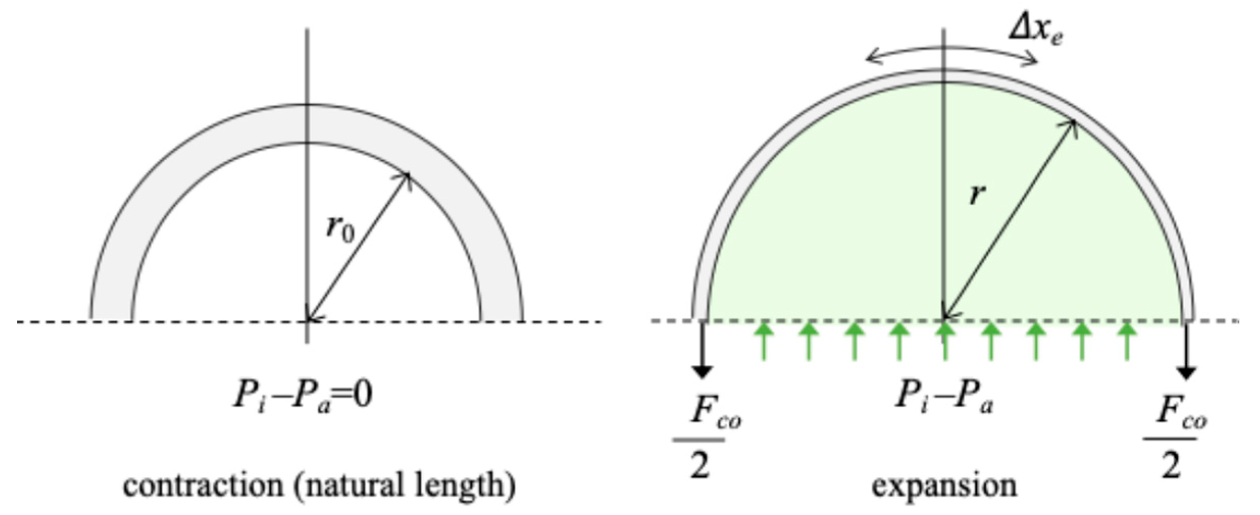
2.2. Hysteresis Occurring Mechanism of RLAM

In the case of PAM, the elastic force of the rubber acts in the direction of contraction of the air chamber, so that the artificial muscles also move in the direction of extension when the pressure is decreased. However, in the case of RLAM, the pressure inside the airbag is higher than the atmospheric pressure outside the airbag, so the airbag does not contract even when the pressure is decreased. Friction also occurs between the airbag and the sleeve, which also makes it difficult for the airbag to expand and contract. A simplified model is used to explain this issue. Figure 1 shows the basic model of the McKibben-type artificial muscle’s extension and contraction motion, and parameters are summarized in Table 1. Here, output adjustment coefficient K f is a parameter that converts the force in the expansion direction of the air chamber into the contraction force. The McKibben-type artificial muscle uses a pantograph mechanism of net sleeve to convert these forces. The coefficient K f is used to represent this mechanism.
Where the direction of contraction is positive. If F e x > F c o , PAM contracts and the frictional force F f acts to prevent it. In other words, it acts in the direction of extension. if F e x < F c o , PAM extends, so the frictional force F f acts in the direction of contraction to prevent it. The external force F o u t acts in the direction of extension because it is the force received from the load. Taking these considerations into account, the direction of the frictional force F f is different when the PAM is contracting and when it is extending, respectively, the external force F o u t in each condition can be expressed as follows:
F o u t = K f F e x F c o F f , F e x > F c o   : P A M   c o n t r a c t i o n ,
F o u t = K f F e x F c o + F f , F e x < F c o   : P A M   e x t e n s i o n .
Here, we express F e x and F f using the pressure difference P i P a as follows:
F e x = P i P a S ,
F f = μ P i P a S .
From these equations, the pressure in the air chamber during extension and contraction P i E and P i C is derived as follows:
P i C = F o u t + K f F c o K f μ S + P a , ( F e x > F c o ) ,
P i E = F o u t + K f F c o K f + μ S + P a , F e x < F c o .
Figure 2 shows a model of the upper half of the cross-sectional model when the air chamber is a rubber tube. In Figure 2, the air chamber radius at natural length is r o , the radius at expansion is r , the circumferential elongation due to air chamber expansion is Δ x e , and the elastic modulus of the rubber is K R , the contraction force F c o is shown as follows:
F c o = K R Δ x e = 2 π K R r r 0 .
The results show that when the air chamber is composed of rubber tube, the force F c o in the direction of contraction increases with increasing the radius of expansion.
In the case of RLAM, the air chamber is an air bag made of non-stretchable material. Therefore, F c o 0 . Comparing Equations (5) and (6), even if the external force F o u t is the same, if F c o is small or μ is large, P i C will be larger than P i E , and this difference is considered the cause of hysteresis. As shown in Figure 3, RLAM has large hysteresis, making it difficult to use in systems that require extension and contraction because control is complicated, or sufficient control performance cannot be obtained.
From the result of Equations (5) and (6), the influence of the friction coefficient μ must be reduced to improve hysteresis. The second term P a on the right side of Equations (5) and (6) is the lower limit of the internal pressure P i C and P i E . If P a is replaced by P o , which can be operated, on the right side, the difference between the first term which includes μ and second term becomes smaller as P o is increased. Therefore, the influence of the friction μ can be reduced, and Equations (5) and (6) become almost the same value. From this consideration, it can be said that hysteresis can be expected to be eliminated by allowing the pressure outside of the air bag to be operated as P o . Based on the above considerations, we propose a double air chambers pneumatic artificial muscle that can regulate the pressure both inside and outside of the air bag.

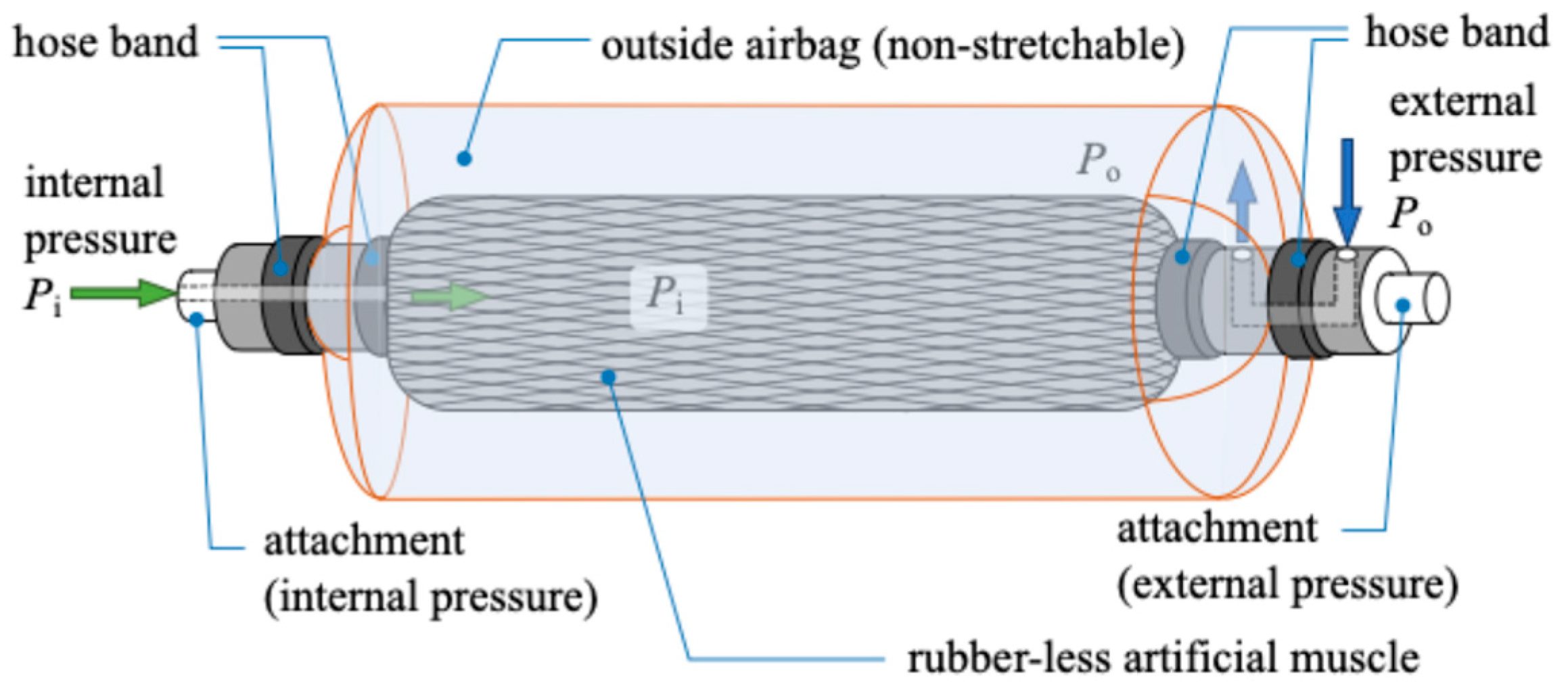
2.3. Double Air Chambers Pneumatic Artificial Muscle (W-PAM)

In this study, we propose W-PAM with a pressurized layer on the outside of the RLAM to actively compress the airbag and improve the RLAM’s motion characteristics in the extension direction. The structure and a cross section of the prototyped W-PAM are shown in Figure 4 and Figure 5, respectively. The W-PAM consists of an airbag made of a composite of non-stretchable polyester and polyethylene sheet on the outside of the RLAM (outer airbag) and is operated by the internal pressure P i applied to the inner airbag of the RLAM and the external pressure P o applied between the RLAM and outer airbag as shown in Figure 6. The left and right attachments shown in Figure 4 have different air flow paths, allowing for adjustment of the internal pressure P i and external pressure P o . This allows the inner airbag of the RLAM to be pressurized from the outside by applying external pressure P o , which is thought to enable the RLAM to be actively extended. The W-PAM is contracted by the RLAM which is placed inside, and the maximum contraction displacement is decided by the length of inner RLAM. In this case, the effective natural length of the inner RLAM is 350 mm, the diameter at natural length is 22 mm, and the diameter at maximum inflation is 42 mm. The outer airbag was set to 420 mm in length and 60 mm in diameter to avoid affecting the extension and contraction of the inner RLAM, taking into consideration the effective natural length and the length of the attachment. The possibility of applying the W-PAM to a system that requires extension and contraction is discussed by controlling the amount of contraction by adjusting the internal and external pressure.
First, the relationship between internal pressure P i and the contraction displacement x is obtained as one of the fundamental characteristics. Some characteristics of the W-PAM are measured using the experimental system shown in Figure 7. The W-PAM is suspended vertically, with a load cell at the upper end to measure the contraction force, a hook for suspending the load, and a linear encoder at the lower end to measure the amount of contraction. The internal pressure P i and external pressure P o are regulated by electro-pneumatic regulators. The electro-pneumatic regulator used in this experiment was the ITV 2031 from SMC (Chiyoda City, Japan). The maximum flow rate is 1500 L/min and the pressure can be adjusted from 0.005 MPa to 0.5 MPa. It has an internal pressure gauge and an analogue output to measure the pressure. Each pressure is measured by a pressure gauge in the electro-pneumatic regulators.
The experimental results of the relationship between the amount of contraction x and the internal pressure P i when the load is varied are shown in Figure 8. As can be seen from the results, when no external pressure P o is applied, the contraction characteristics are almost the same as those of RLAM, the amount of contraction increases curvilinearly with an increase in internal pressure P i . The amount of contraction does not change for a while after the pressure is decreased, and then rapidly extends when the pressure is further decreased.
The change in hysteresis characteristics when external pressure P o is applied to the W-PAM is experimentally confirmed. As the simplest way to reduce hysteresis, a constant external pressure P o is applied only when the internal pressure P i is decreased. One of the experimental results is shown in Figure 9. The results were obtained when the load F was 50 N, 100 N, and 150 N, and the external pressure P o was 0.04 MPa.
From the experimental result, the hysteresis loop becomes smaller when the external pressure P o is applied. However, there are cases where the hysteresis loop crosses depending on the load condition, and the tendency of the hysteresis loop changes. This result indicates that the hysteresis can be reduced by applying the external pressure P o , but the external pressure P o should be controlled appropriately according to the load and other conditions. The appropriate external pressure P o varies depending on the conditions of load and the amount of contraction.

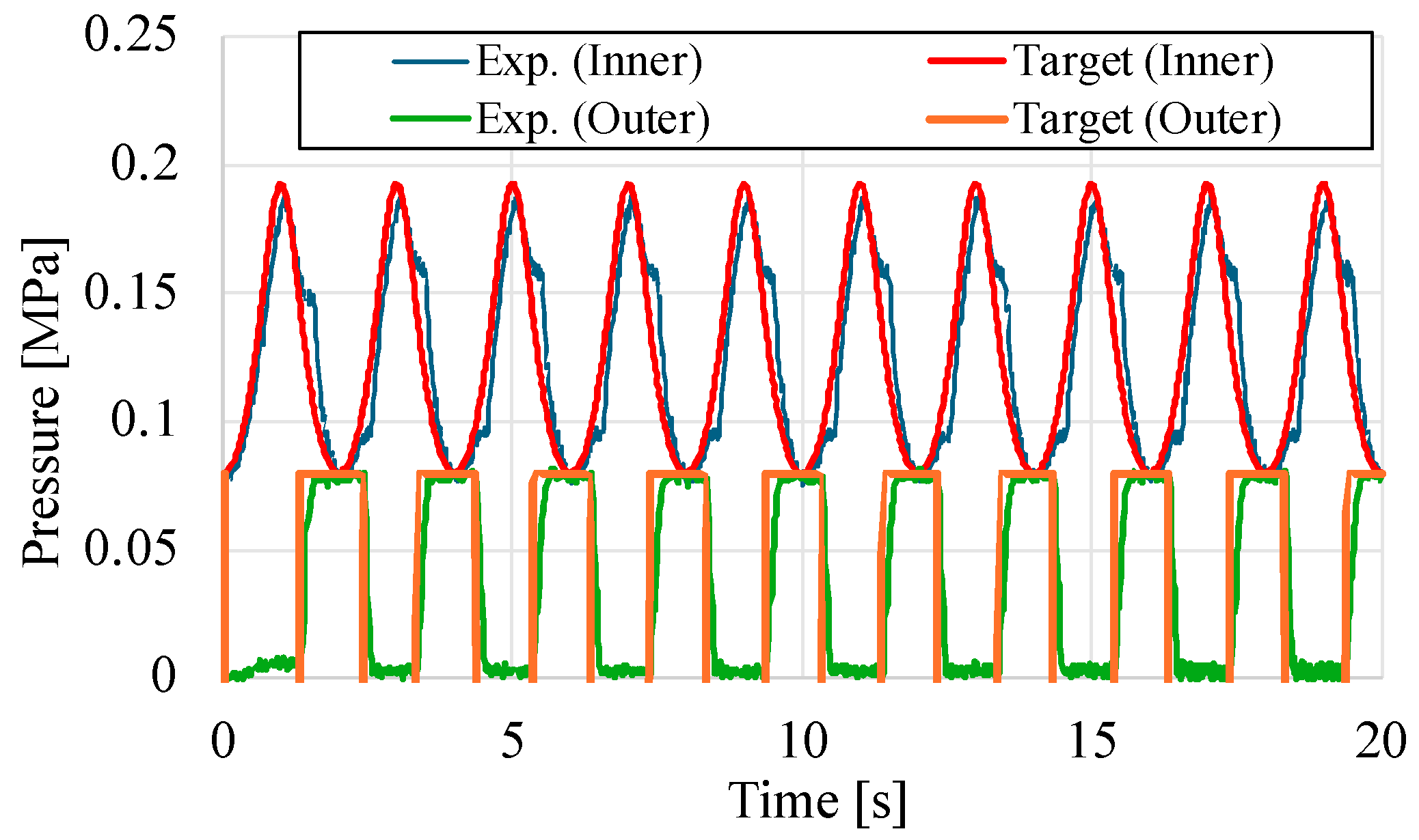
3. Operation of External Pressure Based on the Feedback Control

Considering the relationship between the external pressure and contraction displacement of W-PAM, we propose a method to operate the external pressure P o by feedback control to respond to various conditions. Since the W-PAM regulates two types of pressure, consider the double-acting cylinder shown in Figure 10 as a simplified model. The contractional direction x is the positive direction of displacement, and the positive direction of contraction force F is set in the same direction. Let F i be the force caused by the internal pressure P i and F o be the force caused by the external pressure P o . The mass and damping term of the piston are denoted as m and c , respectively, and the equation of motion becomes as follows:
m x ¨ = F + F i F o c x ˙ ,
thus, summarized by Laplace transform, the equation of motion is as follows:
X s = 1 m s 2 + c s   { F s + F i s F o s } .
Here, the load is defined as follows:
F A s = F s F i s ,
Equation (9) can then be summarized as follows:
X s = 1 m s 2 + c s   { F A s F o s } .
Here, assuming the force F o = A o P o s , Equation (11) becomes:
X s = 1 m s 2 + c s   { F A s A o P o s }   .
In other words, assuming the contraction force F s and the internal pressure   P i s are constant, F A   s also becomes a constant value, which corresponds to a system that considers this as an input disturbance. The absence of hysteresis means that the amount of contraction X ( s ) should be uniquely determined regardless of the manipulation of the internal pressure P i s . Therefore, here, the target contraction amount x r is set based on the internal pressure P i and contraction force F using the mechanical equilibrium model [28], and position control is performed without being affected by the input disturbance F A s .
A block diagram of the feedback control system considering Equation (12) is shown in Figure 11, where C s is the controller. The closed-loop transfer function G y r s from the target value x r to the output x when a PI controller is used is as follows:
G y r s = K p s + K I m s 3 + c s 2 K p s + K I   .
Therefore, the target value response characteristic is good.
Next, to evaluate the disturbance suppression characteristic, the closed-loop transfer function G y d s from disturbance d to output x is obtained as follows:
G y d s = s m s 3 + c s 2 K p s + K I   .
Therefore, the disturbance suppression characteristic is also good. Based on the above, this paper experimentally examines the possibility of reducing hysteresis by feedback position control using a PI controller.

4. Experimental Results

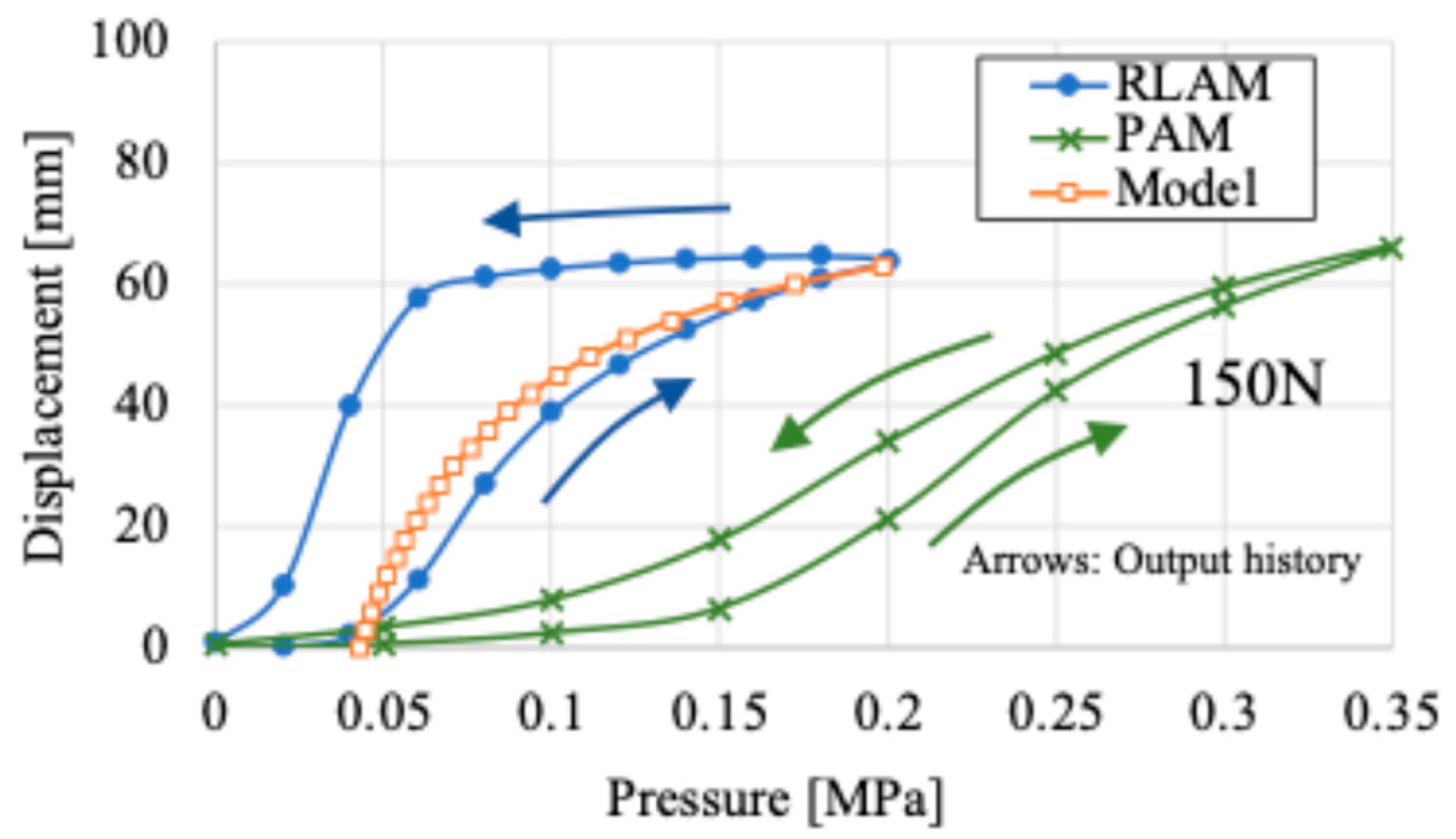
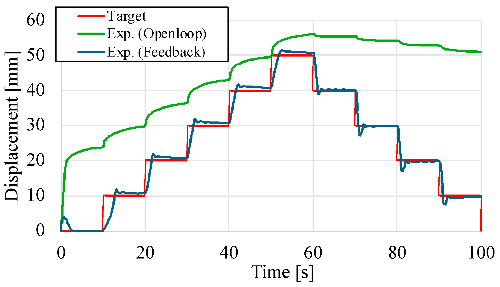
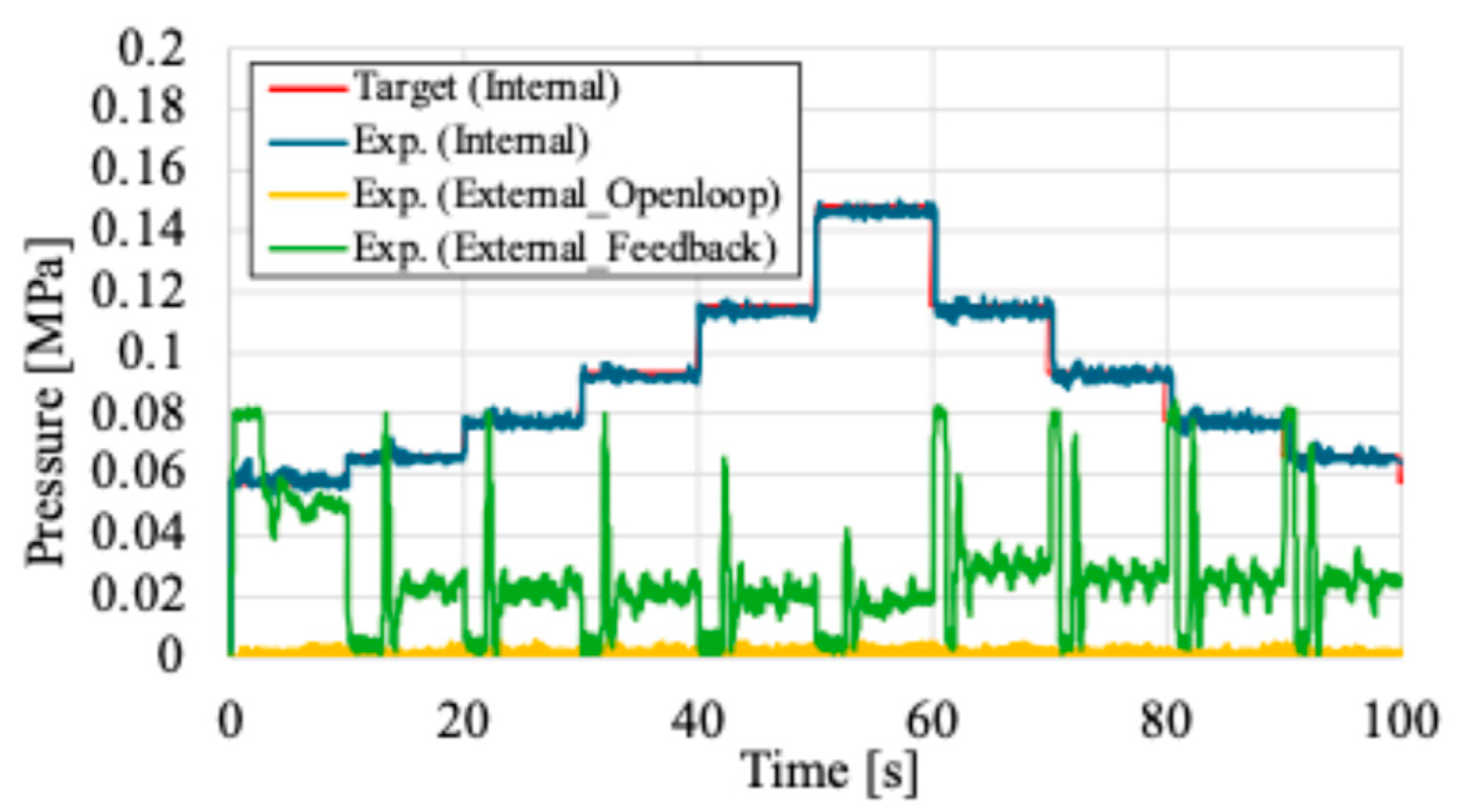
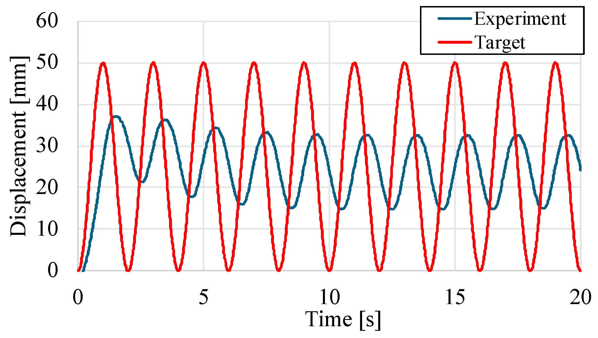
4.1. Hysteresis Elimination by Applying Feedback Control

The position feedback control based on operating the external pressure P o with a PI controller is carried out. In the first experiment, the target contraction displacement was varied at a load of 100 N at 10 mm intervals from 0 mm to 50 mm as a step function. From this target condition, the W–PAM contracts from 0 to 60 s, and after that it extends. The experimental results in the case of the external pressure P o is not applied, which is same as the open loop characteristic, and in the case of the external pressure P o is applied by using the proposed position feedback control are shown in Figure 12, and the result of internal and external pressures at those experimens are shown in Figure 13.
From the results in Figure 12, in the case of open loop, extension and contraction behaviors are different. In particular, after 60 s, the W–PAM is hardly extended. Compared with this result, in the case of applying feedback control based on regulating the external pressure, the response has converged to the target contraction displacement and the steady-state error has disappeared. The feedback control response in Figure 13 shows that the external pressure P o is regulated during both extension and contraction, and combined with Figure 12, the response reaches the target value from the excessive contraction state calculated by the mechanical equilibrium model. From this result, it is confirmed that the feedback control of the external pressure P o is effective of the contraction displacement control of the W–PAM.
Next, the response when the load is changed is shown in Figure 14, Figure 15 and Figure 16. Figure 14 shows the results of the amount of contraction by feedback control with regulating the external pressure, Figure 15 shows the internal and external pressure responses during feedback control, and Figure 16 plots the average of each steady-state response. The PI controller parameters in Figure 14 were determined by trial and error. The P controller parameter and the I controller parameter were finally determined to be 0.1 and 0.008, respectively. The same parameters were used for different load conditions.
Figure 14 shows that the amount of contraction quickly converges to the target value in both the extension and contraction directions under each loading condition. Figure 15 shows that the internal and external pressures change according to the load, respectively. Although the internal pressure is the result of model calculations, the external pressure is also appropriately adjusted in response to the internal pressure, and the target contraction is achieved.
Figure 16 shows that the hysteresis loop has been eliminated compared to Figure 8, indicating that the objective of W-PAM has been achieved. For a more quantitative evaluation, Table 2 shows the results of calculating the area of hysteresis loops for each of Figure 8, Figure 9 and Figure 16. Note that these results are normalized with respect to the open-loop characteristics without external pressure P o , shown in Figure 8.
Table 2 shows that for F = 150 N, the hysteresis loop remains slightly after applying feedback control, but it can be considered to have been almost eliminated because of its small order of magnitude.
These results suggest the possibility of achieving the target contraction without hysteresis by applying external pressure-regulated-type feedback control to the W-PAM.

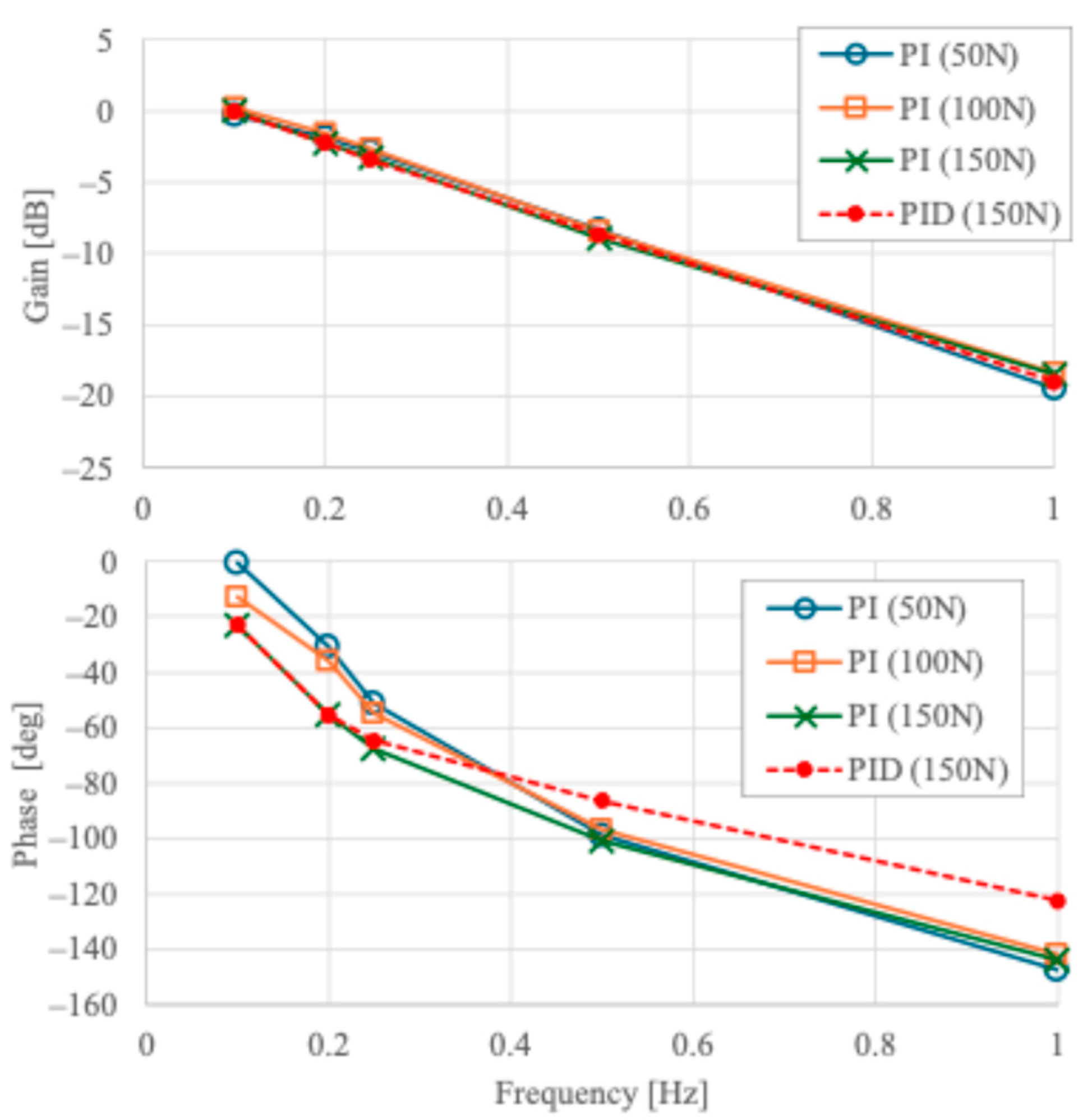
4.2. Frequency Response of Proposed Feedback Control

Next, the frequency response is evaluated. Figure 17 shows the amplitude gain and phase lag of the frequency response for loads of 50, 100, and 150 N, input amplitude of 25 mm, and frequencies of 0.1, 0.2, 0.25, 0.5, and 1.0 Hz, comparing PI and PID as feedback controllers. The P and I parameters are the same for PI and PID. First, the frequency response of the PI controller with respect to the magnitude of the load is discussed. Comparing the responses for each load, no change in amplitude gain is observed. The phase lag is almost the same in the frequency band above 0.5 Hz, but in the slower frequency band, the phase lag tends to be smaller at lower loads. Since both internal and external pressures tend to increase with increasing load, the output from the controller must also be increased. However, since the parameters of the controller were not adjusted according to changes in the load in this experiment, it is considered that the controller is unable to adjust the pressure sufficiently in response to the load, resulting in a tendency for the phase lag to increase. On the other hand, no difference due to load is observed in the higher frequency range than around 0.5 Hz, but this is because the frequency range is sufficiently high and the system using the PI controller operates at almost the limit velocity, so no difference is observed. Next, the difference in frequency response between the PI and PID controllers at a load of 150 N was examined. No difference in amplitude gain is observed, but the phase delay is smaller when the PID controller is used. The D controller parameter was set to 0.004 by trial and error. This is an effect of the phase advance characteristic of the D controller.
Finally, the effect of setting the upper limit of the external pressure to 0.08 MPa is discussed. Figure 18 and Figure 19 show the response of the amount of contraction displacement, internal pressure, and external pressure at a load of 150 N and 0.5 Hz, respectively. These results show that the amount of contraction displacement changes at a nearly constant period, and that the external pressure reaches 0.08 MPa, the highest value set, with a slight delay relative to the target value. This indicates that the response of the system when the amplitude decreases has reached the limit velocity of the system. The maximum value of the external pressure is set in consideration of the durability of the structure, but we expect the amplitude gain to improve as the durability improves and a larger value can be set.

5. Conclusions

In this study, we proposed a double air chambers artificial muscle (W-PAM) that operates by regulating two pressures with the aim of eliminating hysteresis in the extension and contraction motion of the artificial muscle. In this study, we aimed to represent the open-loop characteristics of pneumatic artificial muscles using a mechanical equilibrium model, and determined the internal pressure based on this model. To eliminate hysteresis, an external pressure-regulated position feedback control system was proposed, and its usefulness was experimentally confirmed. The results obtained are summarized below.
  • Hysteresis was eliminated by controlling the amount of contraction using external pressure-regulated position feedback control of W-PAM.
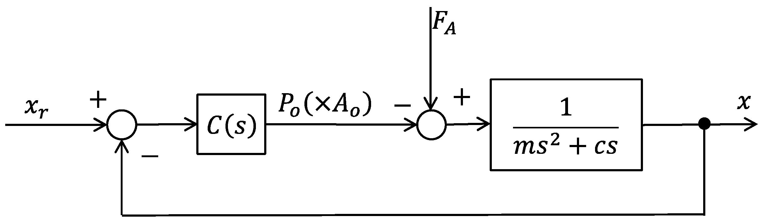
  • The response of the external pressure-regulated position feedback control of W-PAM was predicted using a simplified double air chambers cylinder model, and the results showed that the characteristics were equivalent to those of the position feedback control of a type 1 system with input disturbance. The results of the analysis and experiments confirmed that the controller including an integrator can achieve good results without steady-state error and with good disturbance suppression characteristics.
  • The position feedback control of W-PAM with external pressure operation was compared between PI and PID controllers and the results showed that the amplitude gain did not change, but the phase lag increased with increasing load. It was also confirmed that the phase lag was smaller with the PID controller.
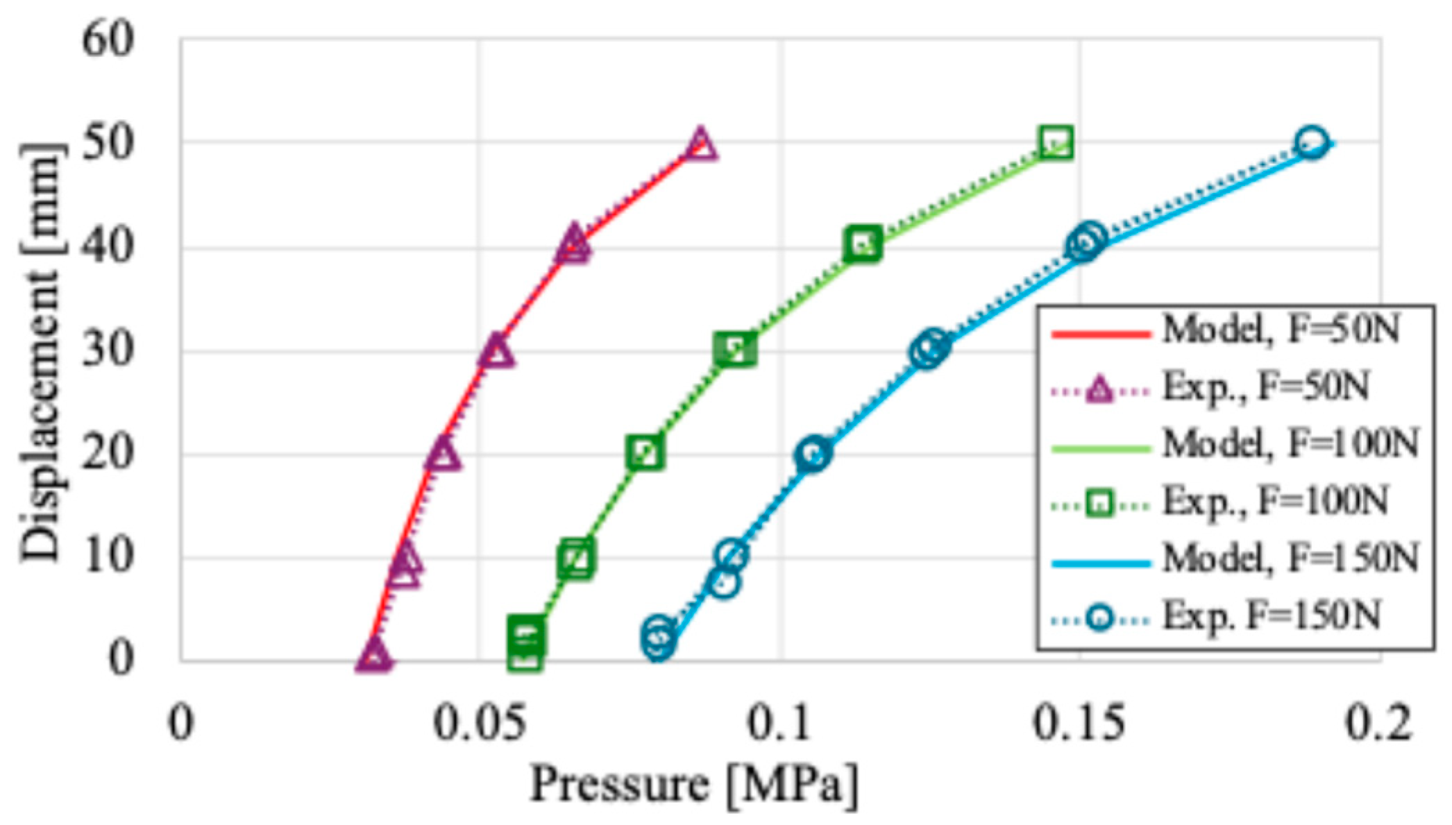
  • It is indicated that W-PAM and the external pressure-regulated position feedback control are useful to represent the W-PAM in a mechanical equilibrium model and to obtain a response without hysteresis.

Author Contributions

Conceptualization, N.S. (Naoki Saito); methodology, N.S. (Naoki Saito) and T.S.; software, N.S. (Naoki Saito); validation, N.S. (Naoki Saito) and N.S. (Norihiko Saga); formal analysis, N.S. (Naoki Saito); investigation, N.S. (Naoki Saito); resources, N.S. (Naoki Saito); data curation, N.S. (Naoki Saito); writing—original draft preparation, N.S. (Naoki Saito); writing—review and editing, N.S. (Naoki Saito), T.S. and N.S. (Norihiko Saga); visualization, N.S. (Naoki Saito); supervision, N.S. (Naoki Saito) and N.S. (Norihiko Saga); project administration, N.S. (Naoki Saito); funding acquisition, N.S. (Naoki Saito). All authors have read and agreed to the published version of the manuscript.

Funding

This work was supported by JSPS KAKENHI Grant Number 21K03839.

Data Availability Statement

The research data are available from the corresponding author, N. Saito on reasonable request.

Conflicts of Interest

The authors declare no conflicts of interest. The funders had no role in the design of the study; in the collection, analyses, or interpretation of data; in the writing of the manuscript; or in the decision to publish the results.

References

  1. Ohta, P.; Valle, L.; King, J.; Low, K.; Yi, J.; Atkeson, C.G.; Park, Y.-L. Design of a Lightweight Soft Robotic Arm Using Pneumatic Artificial Muscles and Inflatable Sleeves. Soft Robot. 2018, 5, 204–215. [Google Scholar] [CrossRef] [PubMed]
  2. Tondu, B.; Ippolito, S.; Guiochet, J.; Daidie, A. A Seven-Degrees-of-Freedom Robot-Arm Driven by Pneumatic Artificial Muscles for Humanoid Robots. Int. J. Robot. Res. 2005, 24, 257–274. [Google Scholar] [CrossRef]
  3. Zanchettin, A.M.; Bascetta, L.; Rocco, P. Acceptability of Robotic Manipulators in Shared Working Environments through Human-like Redundancy Resolution. Appl. Ergon. 2013, 44, 982–989. [Google Scholar] [CrossRef]
  4. Tsai, C.-S.; Hu, J.-S.; Tomizuka, M. Ensuring Safety in Human-Robot Coexistence Environment. In Proceedings of the 2014 IEEE/RSJ International Conference on Intelligent Robots and Systems, Chicago, IL, USA, 14–18 September 2014; pp. 4191–4196. [Google Scholar]
  5. Gopura, R.A.R.C.; Bandara, D.S.V.; Kiguchi, K.; Mann, G.K.I. Developments in Hardware Systems of Active Upper-Limb Exoskeleton Robots: A Review. Robot. Auton. Syst. 2016, 75, 203–220. [Google Scholar] [CrossRef]
  6. Young, A.J.; Ferris, D.P. State of the Art and Future Directions for Lower Limb Robotic Exoskeletons. IEEE Trans. Neural Syst. Rehabil. Eng. 2017, 25, 171–182. [Google Scholar] [CrossRef]
  7. Dollar, A.M.; Herr, H. Lower Extremity Exoskeletons and Active Orthoses: Challenges and State-of-the-Art. IEEE Trans. Robot. 2008, 24, 144–158. [Google Scholar] [CrossRef]
  8. Yan, T.; Cempini, M.; Oddo, C.M.; Vitiello, N. Review of Assistive Strategies in Powered Lower-Limb Orthoses and Exoskeletons. Robot. Auton. Syst. 2015, 64, 120–136. [Google Scholar] [CrossRef]
  9. Giovacchini, F.; Vannetti, F.; Fantozzi, M.; Cempini, M.; Cortese, M.; Parri, A.; Yan, T.; Lefeber, D.; Vitiello, N. A Light-Weight Active Orthosis for Hip Movement Assistance. Robot. Auton. Syst. 2015, 73, 123–134. [Google Scholar] [CrossRef]
  10. Asbeck, A.T.; De Rossi, S.M.M.; Holt, K.G.; Walsh, C.J. A Biologically Inspired Soft Exosuit for Walking Assistance. Int. J. Robot. Res. 2015, 34, 744–762. [Google Scholar] [CrossRef]
  11. Gorissen, B.; Reynaerts, D.; Konishi, S.; Yoshida, K.; Kim, J.-W.; De Volder, M. Elastic Inflatable Actuators for Soft Robotic Applications. Adv. Mater. 2017, 29, 1604977. [Google Scholar] [CrossRef]
  12. Nakamura, T. Fluid-Driven Soft Actuators for Soft Robots. J. Robot. Mechatron. 2024, 36, 251–259. [Google Scholar] [CrossRef]
  13. Polygerinos, P.; Correll, N.; Morin, S.A.; Mosadegh, B.; Onal, C.D.; Petersen, K.; Cianchetti, M.; Tolley, M.T.; Shepherd, R.F. Soft Robotics: Review of Fluid-Driven Intrinsically Soft Devices; Manufacturing, Sensing, Control, and Applications in Human-Robot Interaction. Adv. Eng. Mater. 2017, 19, 1700016. [Google Scholar] [CrossRef]
  14. Ling, Y.Y.; Leong, S.S.; Yee, Y.W. A Review of 3D Printing Processes and Materials for Soft Robotics. Rapid Prototyp. J. 2020, 26, 1345–1361. [Google Scholar] [CrossRef]
  15. Gul, J.Z.; Sajid, M.; Rehman, M.M.; Siddiqui, G.U.; Shah, I.; Kim, K.-H.; Lee, J.-W.; Choi, K.H. 3D Printing for Soft Robotics—A Review. Sci. Technol. Adv. Mater. 2018, 19, 243–262. [Google Scholar] [CrossRef]
  16. Lee, H.; Jang, Y.; Choe, J.K.; Lee, S.; Song, H.; Lee, J.P.; Lone, N.; Kim, J. 3D-Printed Programmable Tensegrity for Soft Robotics. Sci. Robot. 2020, 5, eaay9024. [Google Scholar] [CrossRef]
  17. Chou, C.-P.; Hannaford, B. Measurement and Modeling of McKibben Pneumatic Artificial Muscles. IEEE Trans. Robot. Autom. 1996, 12, 90–102. [Google Scholar] [CrossRef]
  18. Tondu, B. Analysis and Modeling of the Dynamic Behaviour of the McKibben Artificial Muscle. IFAC Proc. Vol. 1997, 30, 295–300. [Google Scholar] [CrossRef]
  19. Tondu, B.; Lopez, P. Modeling and Control of McKibben Artificial Muscle Robot Actuators. IEEE Control Syst. 2000, 20, 15–38. [Google Scholar] [CrossRef]
  20. Tondu, B. Modelling of the McKibben Artificial Muscle: A Review. J. Intell. Mater. Syst. Struct. 2012, 23, 225–253. [Google Scholar] [CrossRef]
  21. Tondu, B.; Lopez, P. The McKibben Muscle and Its Use in Actuating Robot-arms Showing Similarities with Human Arm Behaviour. Ind. Robot. Int. J. 1997, 24, 432–439. [Google Scholar] [CrossRef]
  22. Ferraresi, C.; Franco, W.; Bertetto, A.M. Straight Fibres Pneumatic Muscle: An Actuator with High Traction Force. In Proceedings of the Sixth International Conference on Fluid Power, Tampere, Finland, 26–28 May 1999; pp. 787–798. [Google Scholar]
  23. Durante, F.; Antonelli, M.G.; Beomonte Zobel, P.; Raparelli, T. A Procedure for the Fatigue Life Prediction of Straight Fibers Pneumatic Muscles. Actuators 2021, 10, 300. [Google Scholar] [CrossRef]
  24. Durante, F.; Antonelli, M.; Zobel, P.B.; Raparelli, A. Development of a Straight Fibers Pneumatic Muscle. Int. J. Autom. Technol. 2018, 12, 413–423. [Google Scholar] [CrossRef]
  25. Kojima, A.; Okui, M.; Hisamichi, I.; Tsuji, T.; Nakamura, T. Straight-Fiber-Type Artificial Muscle Deformation Under Pressurization. IEEE Robot. Autom. Lett. 2019, 4, 2592–2598. [Google Scholar] [CrossRef]
  26. Nakamura, T.; Shinohara, H. Position and Force Control Based on Mathematical Models of Pneumatic Artificial Muscles Reinforced by Straight Glass Fibers. In Proceedings of the 2007 IEEE International Conference on Robotics and Automation, Rome, Italy, 10–14 April 2007; pp. 4361–4366. [Google Scholar]
  27. Sato, T.; Saito, N.; Ogasawara, T.; Sato, T. Development of Rubberless Artificial Muscle and Fundamental Characteristics. In Proceedings of the IECON 2011-37th Annual Conference of the IEEE Industrial Electronics Society, Melbourne, VIC, Australia, 7–10 November 2011; pp. 2124–2129. [Google Scholar]
  28. Saito, N.; Sato, T.; Ogasawara, T.; Takahashi, R.; Sato, T. Mechanical Equilibrium Model of Rubberless Artificial Muscle and Application to Position Control of Antagonistic Drive System. Ind. Robot. Int. J. 2013, 40, 347–354. [Google Scholar] [CrossRef]
  29. Saito, N.; Satoh, T. Structure of a Rubberless Artificial Muscle and Evaluation of a Lifetime. In Proceedings of the IECON 2016-42nd Annual Conference of the IEEE Industrial Electronics Society, Florence, Italy, 23–26 October 2016; pp. 648–653. [Google Scholar]
  30. Saito, N.; Satoh, T. Force and Position Control of Rubberless Artificial Muscle Antagonistic Drive System. JFPS Int. J. Fluid Power Syst. 2014, 8, 44–51. [Google Scholar] [CrossRef]
  31. Daerden, F.; Lefeber, D. The Concept and Design of Pleated Pneumatic Artificial Muscles. Int. J. Fluid Power 2001, 2, 41–50. [Google Scholar] [CrossRef]
  32. Verrelst, B.; Van Ham, R.; Vanderborght, B.; Lefeber, D.; Daerden, F.; Van Damme, M. Second Generation Pleated Pneumatic Artificial Muscle and Its Robotic Applications. Adv. Robot. 2006, 20, 783–805. [Google Scholar] [CrossRef]
  33. Drozdov, A.D.; Christiansen, J.D. Constitutive Equations for the Nonlinear Elastic Response of Rubbers. Acta Mech. 2006, 185, 31–65. [Google Scholar] [CrossRef]
  34. Saito, N.; Satoh, T. Posture Control Considering Joint Stiffness of a Robotic Arm Driven by Rubberless Artificial Muscle. Int. J. Autom. Technol. 2016, 10, 503–510. [Google Scholar] [CrossRef]
  35. Al-Fahaam, H.; Nefti-Meziani, S.; Theodoridis, T.; Davis, S. The Design and Mathematical Model of a Novel Variable Stiffness Extensor-Contractor Pneumatic Artificial Muscle. Soft Robot. 2018, 5, 576–591. [Google Scholar] [CrossRef]
  36. Hassan, T.; Cianchetti, M.; Moatamedi, M.; Mazzolai, B.; Laschi, C.; Dario, P. Finite-Element Modeling and Design of a Pneumatic Braided Muscle Actuator With Multifunctional Capabilities. IEEE/ASME Trans. Mechatron. 2019, 24, 109–119. [Google Scholar] [CrossRef]
  37. Zheng, H.; Shen, X. Double-Acting Sleeve Muscle Actuator for Bio-Robotic Systems. Actuators 2013, 2, 129–144. [Google Scholar] [CrossRef] [PubMed]
Figure 1. Extension and contraction mechanism of the PAM.
Actuators 13 00282 g001
Figure 2. Upper half of cross-sectional model of the air chamber of PAM.
Actuators 13 00282 g002
Figure 3. Contractional characteristic of PAM and RLAM.
Actuators 13 00282 g003
Figure 4. Structure of W-PAM.
Actuators 13 00282 g004
Figure 5. Cross section of W-PAM.
Actuators 13 00282 g005
Figure 6. Pressure distribution of W-PAM.
Actuators 13 00282 g006
Figure 7. Experimental system.
Actuators 13 00282 g007
Figure 8. Relationship between contractional displacement and internal pressure when no external pressure is applied. Arrows in these figures show the output history.
Actuators 13 00282 g008
Figure 9. Relationship between contractional displacement and internal pressure when a constant external pressure is applied. Arrows in these figures show the output history.
Actuators 13 00282 g009
Figure 10. Schematic of double-acting cylinder as a simplified model of W-PAM.
Actuators 13 00282 g010
Figure 11. Block diagram of feedback control system.
Actuators 13 00282 g011
Figure 12. Comparing result of contractional displacement.
Actuators 13 00282 g012
Figure 13. Result of supplying pressures.
Actuators 13 00282 g013
Figure 14. Experimental result of contractional displacement.
Actuators 13 00282 g014
Figure 15. Experimental result of internal and external pressure.
Actuators 13 00282 g015
Figure 16. Comparison results of static characteristics of model and feedback response of W-PAM.
Actuators 13 00282 g016
Figure 17. Comparing results of gain and phase lag characteristics of frequency response of the feedback control based on the external pressure operation using PI controller and PID controller.
Actuators 13 00282 g017
Figure 18. Contraction displacement of the feedback control using PI controller based on the external pressure operation.
Actuators 13 00282 g018
Figure 19. Internal and external pressures of the contraction displacement feedback control using PI controller based on the external pressure operation.
Actuators 13 00282 g019
Table 1. Parameters in Figure 1.
SymbolMeaning
P i Internal pressure
P o Pressure outside of the air chamber
P a Atmospheric pressure
F e x Force in the direction to inflate air chamber
F c o Force in the direction to contraction air chamber
F o u t External force received from load
F f Frictional force between air chamber and mesh sleeve
μ Friction coefficient
S Effective surface area of air chamber
K f Output adjustment coefficient 1
P i E Internal pressure when PAM extends
P i C Internal pressure when PAM contracts
1 Coefficient for converting the expansion force of air chamber into a contraction force of PAM.
Table 2. Hysteresis loop area calculation results (normalized by open-loop results).
Condition50 N100 N150 N
Open   loop   without   P o (Figure 8)1.00001.00001.0000
Open   loop   with   P o = 0.04 MPa (Figure 9)0.70420.18990.0638
Feedback control (Figure 16)0.00080.00190.0170
Disclaimer/Publisher’s Note: The statements, opinions and data contained in all publications are solely those of the individual author(s) and contributor(s) and not of MDPI and/or the editor(s). MDPI and/or the editor(s) disclaim responsibility for any injury to people or property resulting from any ideas, methods, instructions or products referred to in the content.

