Article

Backlash Elimination Control for Robotic Joints with Dual–Motor Drive

1
School of Mechanical Engineering, Shenyang Ligong University, Shenyang 110159, China
2
Science and Technology Development Corporation, Shenyang Ligong University, Shenyang 110003, China
*
Author to whom correspondence should be addressed.
Actuators 2024, 13(8), 291; https://doi.org/10.3390/act13080291
Submission received: 10 July 2024 / Revised: 28 July 2024 / Accepted: 30 July 2024 / Published: 1 August 2024
(This article belongs to the Section Actuators for Robotics)

Abstract

:
Dual–motor drive is commonly used in heavy–duty robotic joint servo systems. However, the backlash inevitably affects joint accuracy. In this article, a variable bias torque control method is proposed for a dual–motor–driven robotic joint. The variable bias torque varies directly according to the motor current, and the conversion method of the bias compensation torque is presented. A simulation model of the dual–motor drive system in MATLAB/Simulink is established based on the dynamic modeling of a dual–motor drive system, and a robotic joint prototype is also established. The variable bias torque control can achieve a reasonable distribution of the output torque for the whole servo cycle and can effectively reduce the energy consumption of the system to maintain static backlash elimination; the dynamic loading of the bias voltage can be achieved through the setting of the conversion function to complete the smooth transition between the two states of backlash elimination control and common drive control; the dynamic loading of the bias torque improves the torque output capability of the dual–motor system. In the experiment, the steady–state error of the servo system is less than 0.05°, and the error is much smaller than the internal backlash angle (about 2°) of the system, which indicates that the internal backlash of the robot joint has been eliminated. The static backlash elimination bias current of the joint is reduced from about 250 mA to about 110 mA, reducing the energy consumption of the servo system effectively.

1. Introduction

Backlash is an important factor affecting the performance of the drive train, especially for high–performance robot joints where the effect of backlash is more prominent [1,2]. In fast–following systems where the motor–driven load changes direction frequently, the transient errors caused by backlash cannot be overcome by using mechanical backlash elimination methods [3,4]. In addition, the mechanical backlash elimination method increases the complexity of mechanical equipment and gradually decreases the backlash elimination reliability of the equipment as the working time increases [5,6,7,8].
Compared with mechanical backlash elimination methods, the electrical backlash elimination method using dual–motor drive not only improves the driving capacity of the system but also eliminates the transmission backlash of the system through reasonable control and has the advantages of simple mechanical structure, high reliability of backlash elimination, and low machining accuracy requirements for transmission parts [9,10,11]. Although the dual–motor drive system adds a set of servo drive mechanisms compared with the single–motor drive system, with the development of servo drive technology and its cost reduction, the dual–motor control method is widely used in the field of heavy–duty servo systems [12,13,14].
Backlash elimination control of a dual–motor drive system requires simultaneous consideration of the coupling control between the two motors to achieve backlash elimination, making the design of the control system more difficult. Various backlash elimination control methods have been proposed by scholars [15,16,17,18]. In the constant torque compensation control, the master motor operates in closed–loop position control. To eliminate the effect of backlash during the drive, the slave motor always provides a constant torque in the opposite direction to the master motor torque to eliminate the backlash. The compensation torque output from the slave motor is equivalent to increasing the load of the system. A small compensation torque cannot eliminate the effect of the backlash, and a larger compensation torque will affect the dynamic response characteristics of the system and the torque output capability of the system [19]. In a dual–motor system, the master motor can operate in a closed–loop position control for precise position control. The speed command of the master motor is input to the speed loop of the slave motor, which is controlled according to the speed command of the master motor [20]. The difference between the current settings of the two motors is output by the controller as an additional speed set point, which is fed back to the speed loop settings of the master and slave motors, respectively, with opposite signs to achieve balanced torque distribution. The system maintains the backlash elimination state requiring the torque output capacity of each motor to be more than one times the torque output capacity of the single motor system, and the torque output capacity of the system in the common drive state is less than the sum of the maximum torque of the two motors due to the presence of the backlash elimination bias torque [21]. Robertz et al. [22] proposed a position–torque conversion control method in which a position–torque conversion control part is added to the slave motor control loop of the system, and through the role of conversion control function, the dual motors are position closed–loop control when they are far from the target position to improve the system response speed; when they are close to the position set point, the main motor position control remains unchanged, and the slave motor is converted to torque control to output a constant torque in the opposite direction of the main motor motion to eliminate the transmission backlash and improve the system positioning accuracy.
In this paper, we aim to improve the transmission accuracy of robot joints by using dual–motor drive and backlash elimination control methods in non–heavy–duty robot joints. Considering the shortcomings of the typical backlash elimination control methods, we propose a variable bias torque control method to eliminate the backlash. We aim to complete the loading of the bias torque when the system is about to show backlash, entering the dual–motor backlash control method; when the system does not show backlash, the bias torque used for backlash elimination is converted into the driving torque of the motors so that the two motors can jointly drive the load in order to increase the torque output capacity, entering the common driving state. In addition, the bias torque for maintaining the backlash elimination can be reduced when the system is stationary, reducing the energy consumption of the system. We take the motor current as a reference for outputting the bias torque dynamically. A conversion function is presented to achieve a smooth conversion between backlash elimination control and common drive control.
This study is organized as follows. In Section 2, we presented the backlash elimination control method for dual–motor drives with variable bias torque based on motor currents. The dynamic modeling of the system is established and simulated using MATLAB in Section 3. In Section 4, the backlash elimination performance is demonstrated by the experimental results. Conclusions are given in Section 5.

2. Variable Bias Torque Control Method

A dual–motor drive not only needs to eliminate gear backlash to improve transmission accuracy but also to give the system a large torque output capability. The transmission backlash is manifested when the direction of the motor torque changes so that the loading of the bias torque can be completed when the direction of the torque is about to change and switch to the dual–motor backlash elimination control mode; in the case that the system does not manifest the backlash, the bias torque used for backlash elimination is converted into the driving torque of the motor so that the two motors drive the load together to increase the torque output capacity of the system, entering the two–motor common drive mode. By measuring the motor current, it is possible to determine the torque applied at the load side and use this current as a reference for the dynamic output of the basis torque.
To realize the smooth conversion between backlash elimination control and common drive control, the whole control process is designed as the backlash elimination control stage, the transition stage of mutual conversion between backlash elimination control and common drive, and the common drive control stage by designing a reasonable conversion function, and the three stages are converted to each other according to the actual working state of the system and the corresponding conversion function.

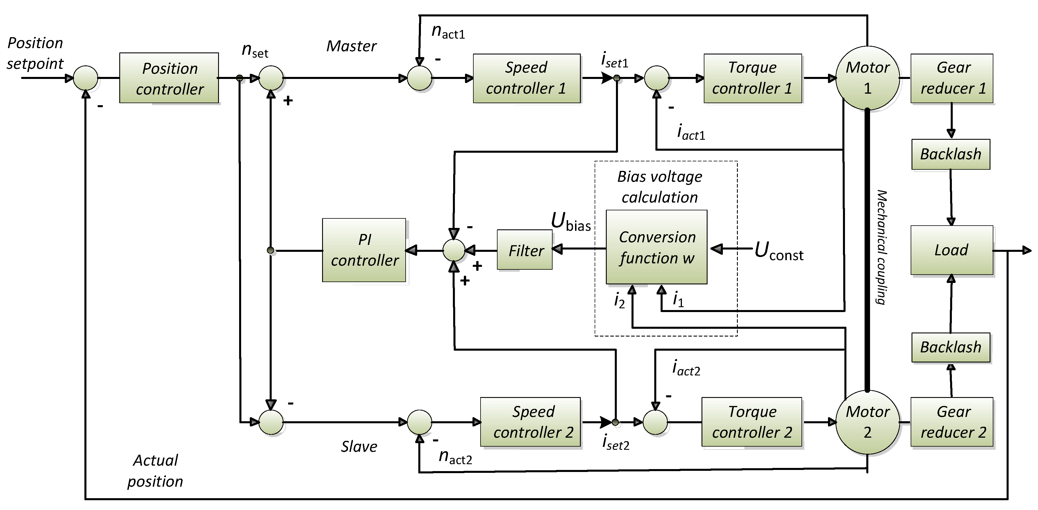
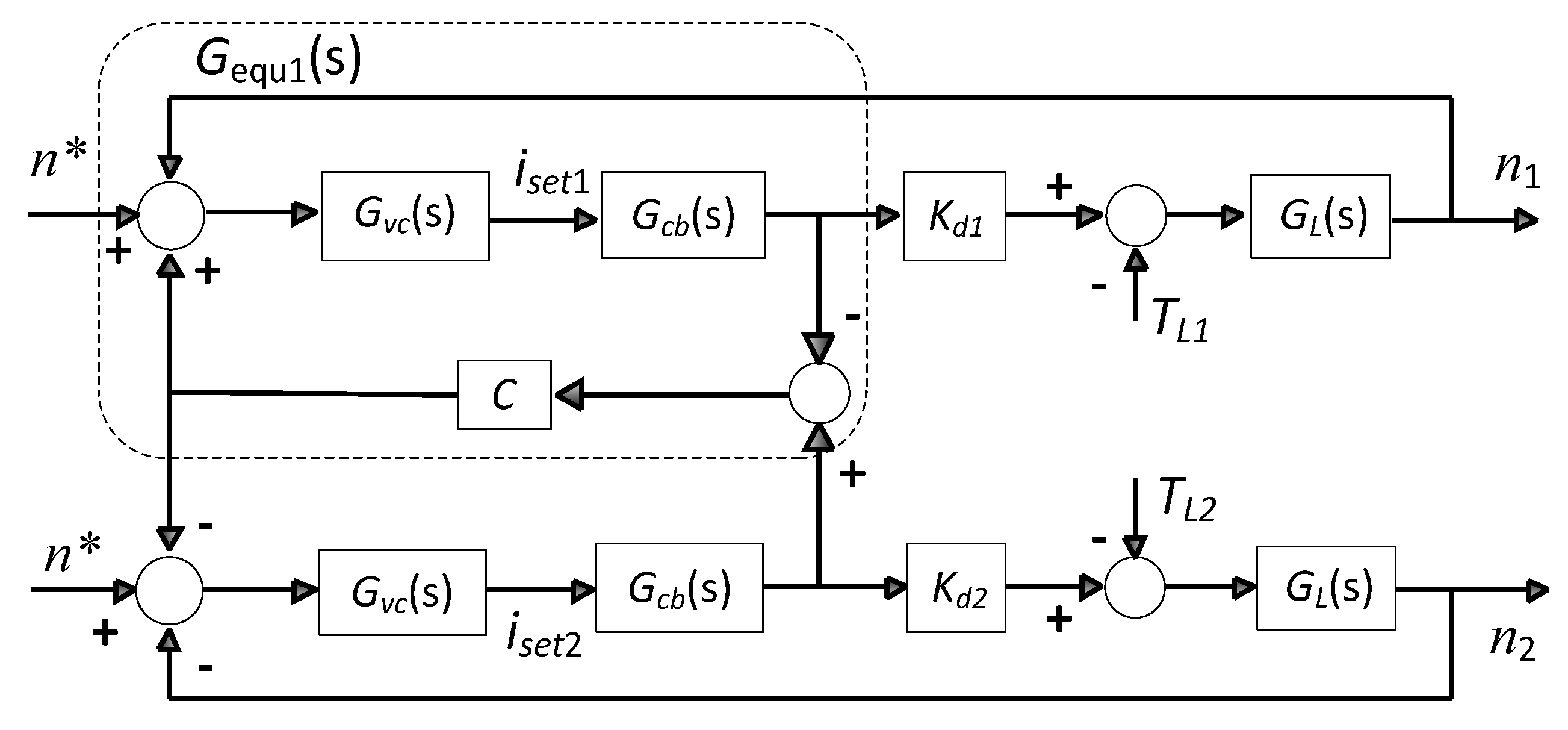
2.1. Control Scheme of the Dual–Motor Drive System

In this article, we take the gear drive joint as the research object. In the dual–motor drive system, the motor output pinion is coupled to the output large gear through the reducer, and the load is driven by the large gear; thus, the structure schematic of the dual–motor drive system is obtained, as shown in Figure 1.
Figure 2 shows the schematic diagram of the variable bias torque backlash elimination control of the dual–motor drive system proposed in this article, in which the control system only performs closed–loop control of the position at the load side to achieve precise positioning during the feeding process, and the slave axis realizes the control of the speed loop according to the operating speed command of the master axis. The compensating voltage controller (PI controller) in the control system serves to equalize the disturbing load and control the bias torque between the master and slave axes. The PI controller balances fast response with the ability to effectively reduce or eliminate static differentials. In addition, PI controllers are simpler and less computationally intensive. The difference of the input signal of the current regulator of the master and slave axes is calculated and output by the PI controller, which is fed back to the speed set point of the master and slave axes, respectively, as an additional amount of speed feed with opposite signs to adjust the torque balance distribution between the master and slave axes to form the torque synchronization control.
The backlash bias voltage Ubias is also output to the master and slave axis speed set points as additional speed feeds with opposite signs through the filter and PI controller, respectively, which indirectly act on the current regulator to create a bias torque between the master and slave axes to eliminate backlash.

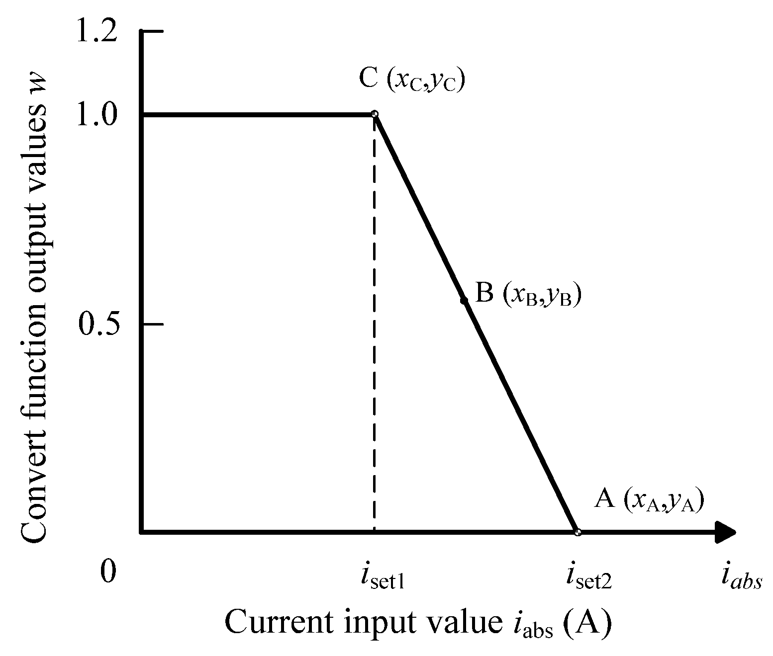
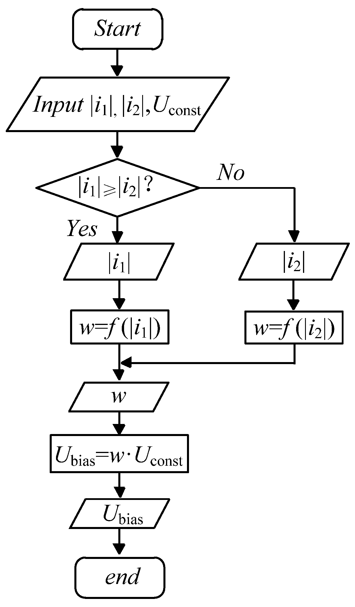
2.2. Calculation of Backlash Elimination Bias Voltage

The bias voltage calculation part of the dual–motor system is shown in the dashed box in Figure 2. The control system first needs to obtain the current values of the DC servo motors, and then the current will be filtered to remove noise and interference signals to facilitate the subsequent calculation. And finally, it takes the absolute value of the currents of the two motors and selects the larger current value as the input value of the conversion function, i.e., the input current value is
i a b s = max i 1 , i 2
where i1 and i2 are the load currents of motor 1 and motor 2, respectively.
To realize the conversion between backlash elimination control and torque synchronous control, the conversion function w is introduced. The correspondence between the input current value iabs and the w value is shown in Equation (2), and the conversion function curve is shown in Figure 3. The set compensation voltage constant Uconst is multiplied with the w value to form a dynamic bias voltage Ubias ∈ [0, Uconst], and the bias voltage value is superimposed at the speed loop given to form a dynamic bias torque Tbias ∈ [0, T0] at the output of the motor, and T0 is the bias torque value corresponding to the compensation voltage Uconst.
w = 1 , i a b s i s e t 1 i a b s i s e t 2 i s e t 1 i s e t 2 , i s e t 1 < i a b s < i s e t 2 0 , i s e t 2 i a b s
where iset1 and iset2 are the current setting values in the conversion function, respectively.
The flowchart of the bias voltage calculation according to the motor currents is shown in Figure 4.

2.3. Method of Selecting the Current Setting Value

The current setting of the conversion function in the backlash elimination control method determines the actual effect, and the bias torque formed between motors is the key to eliminating the transmission backlash. The relationship between the backlash elimination effect and the bias torque under different operating conditions is complex, and for the convenience of application and to ensure the backlash elimination effect, a larger bias torque value is often chosen in engineering; usually, 10–30% of the rated torque of the motor is chosen as the backlash elimination compensation torque [14].
The purpose of designing the backlash elimination control method in this article is to enable the system to output a bias torque for reliable backlash elimination while reducing the static bias torque to reduce energy consumption and have a large torque output capability for non–backlash performance. Therefore, the current setting values in the conversion function need to be set appropriately, and the corresponding conversion function can be obtained by determining the values of points A, B, and C, as shown in Figure 3. Among them, the steps for calculating the current setting value in the conversion function are as follows:
(1) Select 10–30% of the rated torque of the motor as the backlash elimination compensation torque, which forms the bias torque corresponding to the compensation voltage value Uconst, and set the motor current value corresponding to the compensation torque to iset2, i.e., determine the coordinates of point A as (iset2, 0);
(2) The value of the bias torque for the static maintenance of the system backlash elimination should not be chosen too large; it is only necessary to overcome the friction and eliminate the static backlash. Using the motor current value i0 corresponding to the selected static compensation torque as the horizontal coordinate of point B, where i0 < iset2, i0/iset2 is the vertical coordinate of point B, and the coordinate of point B is obtained as (i0, i0/iset2);
(3) According to the already determined coordinates of points A and B, the horizontal coordinates of point C can be calculated by Equation (3) to obtain the coordinates of point C iset1, and the coordinates of point C are determined as (iset1, 1).
i s e t 2 i 0 i s e t 2 i s e t 1 = i 0 i s e t 2 0 < i s e t 1 < i s e t 2

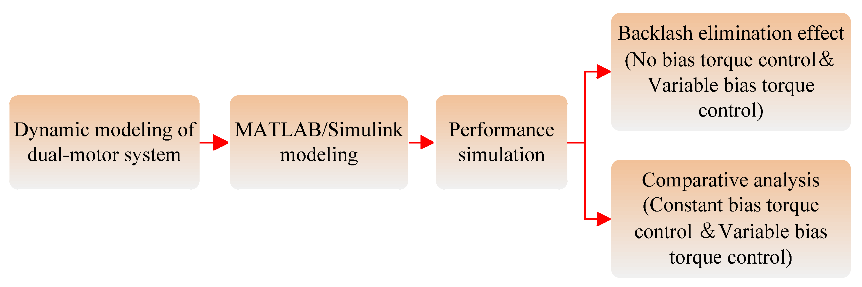
3. Dynamic Modeling and Simulation

In this section, the MATLAB/Simulink simulation model of the dual–motor system is established based on dynamic modeling. The backlash elimination effect of the proposed method and a comparative analysis of constant bias torque control and variable bias torque control are presented. The flowchart of the simulation is shown in Figure 5.

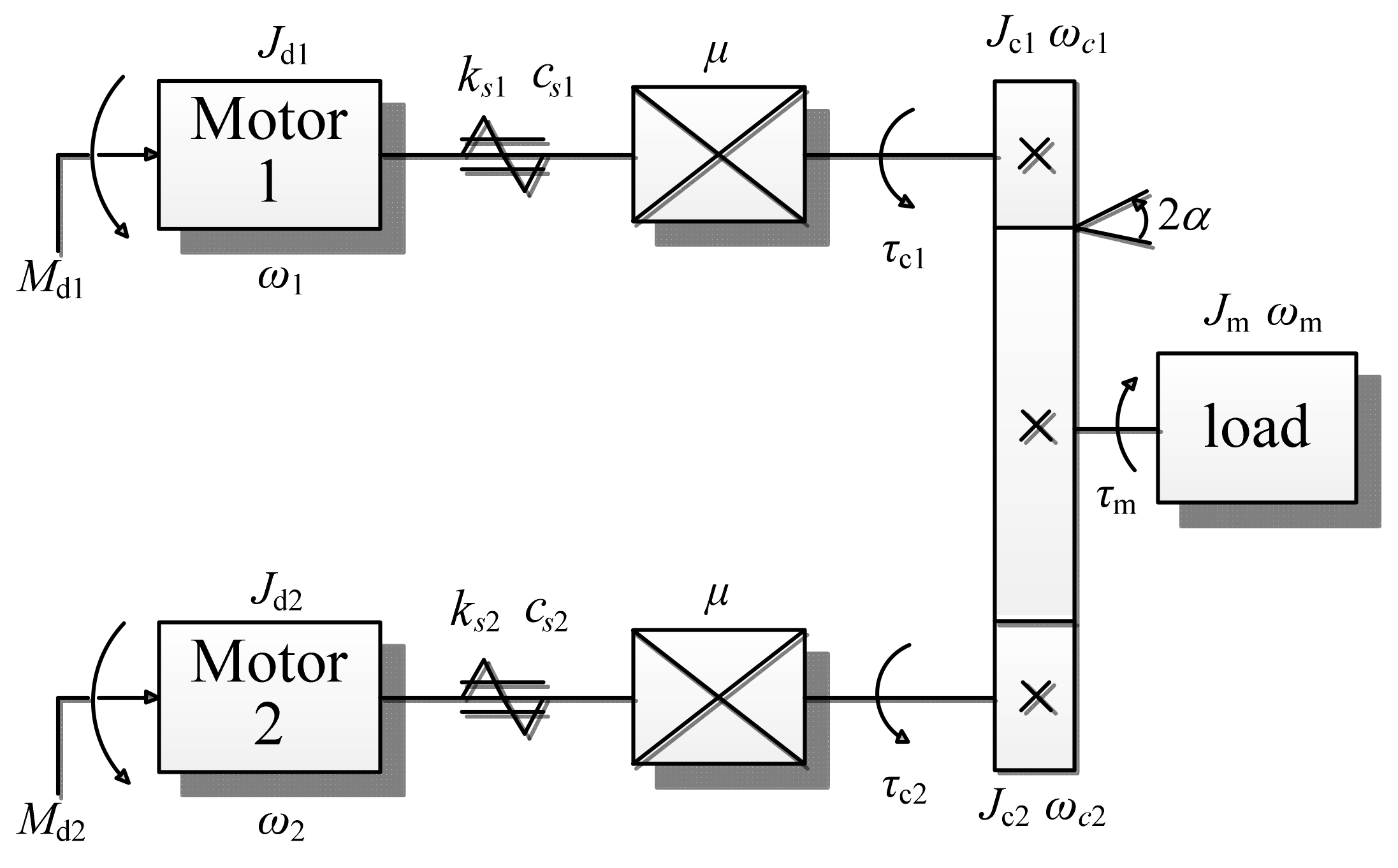
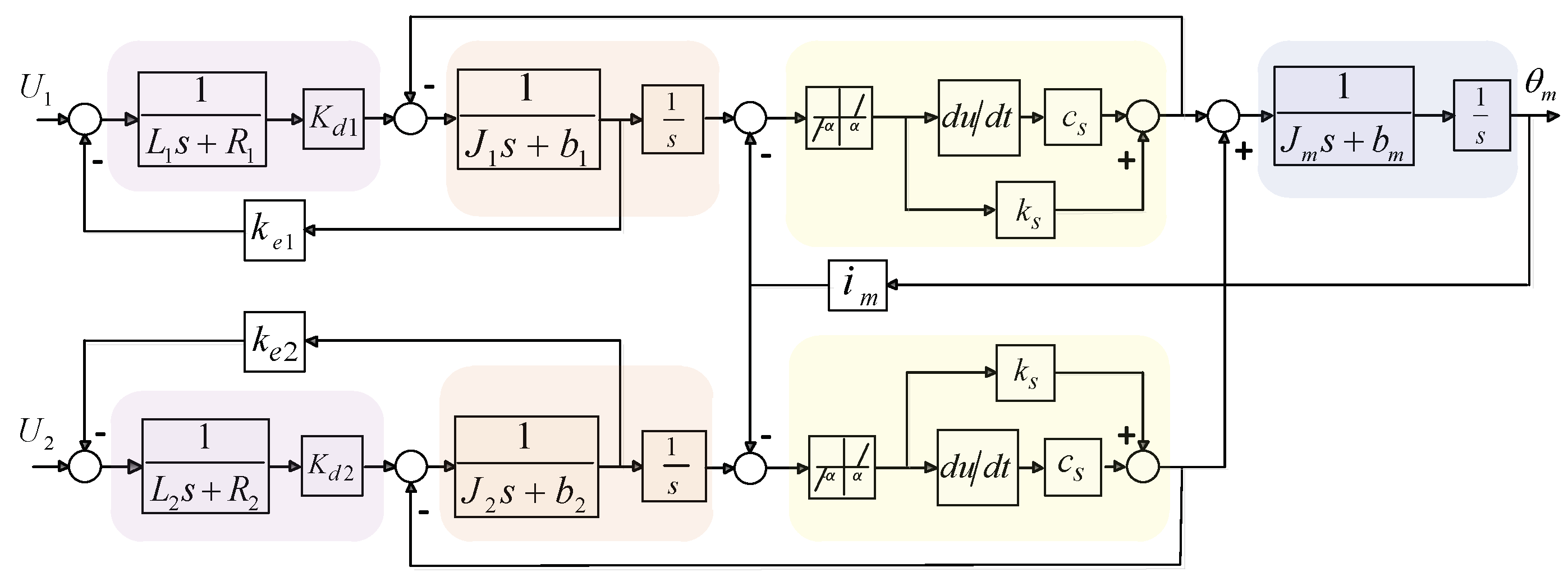
3.1. Dynamics Modeling of the Dual–Motor Drive System

The dual–motor drive system can be simplified as two sets of dual–mass systems containing gear backlash acting together to drag the load, and the simplified model of the dual–motor drive system is shown in Figure 6. M (λ = 1, 2) represents the electromagnetic torque of the motor, ωλ represents the rotational velocity of the motor, and ωcλ represents the rotational velocity of the small pinion. ωm is the rotational velocity of the large gear.
The voltage balance equation of the motor armature circuit in the dual–motor system can be expressed as
C e λ θ ˙ λ + I λ R λ + L λ I ˙ λ = U λ λ = 1 , 2
where Lλ is the inductance of the motor armature circuit, Rλ is the resistance of the motor armature circuit, Iλ is the current of the motor armature circuit, Ceλ is the counter–electromotive force coefficient of the motor, θλ is the motor rotation angle, Uλ is the voltage of the motor armature circuit, and λ is the motor number.
The electromagnetic torque of the motor is proportional to the current, and the electromagnetic torque of the two motors can be expressed as
M d λ = K d λ I λ λ = 1 , 2
where K is the torque coefficient of the motor.
The torque balance equation of the motors can be expressed as
M d λ = J d λ θ ¨ λ + b d λ θ ˙ λ + τ c λ / i m λ = 1 , 2
where Jdλ is the rotational inertia of the motor side, bdλ is the equivalent viscous friction coefficient of the motor, τ is the torque applied to the pinion, and im is the gear ratio.
The dynamic equation of the small pinion can be expressed as
τ c λ = J c λ θ ¨ c λ + b c λ θ ˙ c λ + τ b λ λ = 1 , 2
where τ is the driving torque on small pinions, J is the rotational inertia of the small pinions, b is the equivalent viscous friction coefficient of the small pinions, and θ is the rotation angle of the small pinions.
The relationship between the rotation angle θ of the nth pinion and the rotation angle θλ of the motor shaft can be expressed as
θ λ = μ θ c λ λ = 1 , 2
where μ is the transmission ratio of reducers.
The torque transmitted by the pinions to the large gear at the load end can be expressed as [23]
τ b λ = k s λ ( θ c λ i m θ m α ) + c s λ ( θ ˙ c λ i m θ ˙ m ) , θ c λ i m θ m > α k s λ ( θ c λ i m θ m + α ) + c s λ ( θ ˙ c λ i m θ ˙ m ) , θ c λ i m θ m < α 0 , θ c λ i m θ m α λ = 1 , 2
where k is the elasticity coefficient of the drive shaft; c is the damping coefficient of the transmission system; θm and θ are the rotational angles of the large and the small gears, respectively; and α is half the backlash.
The dynamic equation of the large gear can be expressed as
τ m = J m θ ¨ m + b m θ ˙ m
where Jm is the rotational inertia of the large gear, bm is the equivalent viscous friction coefficient of the large gear, and τm is the moment of the large gear.
The large gear is subjected to the combined torque of the two pinions, which can be expressed as
τ m = i m ( τ b 1 + τ b 2 )
According Equation (8), μ C e λ θ ˙ c λ + I λ R λ + L λ I ˙ λ = U λ , let μC = K, we can obtain
K e λ θ ˙ c λ + I λ R λ + L λ I ˙ λ = U λ λ = 1 , 2
Substituting the multi–motor system dynamics Equations (5) and (7–9) into Equation (6), the dynamics equation of the multi–motor system is obtained
( μ J d λ + J c λ μ ) θ ¨ c λ + ( μ b d λ + b c λ μ ) θ ˙ c λ + τ b λ μ = k d λ I λ λ = 1 , 2
Multiplying both sides of Equation (13) by μ at the same time, we can obtain
( μ 2 J d λ + J c λ ) θ ¨ c λ + ( μ 2 b d λ + b c λ ) θ ˙ c λ + τ b λ = μ k d λ I λ λ = 1 , 2
Let Jλ = μ2J + J, bλ = μ2b + b, Kλ = μk, we can obtain
J λ θ ¨ c λ + b λ θ ˙ c λ + τ b λ = k λ I λ λ = 1 , 2
When (θimθm) > α, it can be derived that
k λ I λ = J λ θ ¨ c λ + b λ θ ˙ c λ + k s λ ( θ c λ i m θ m α ) + c s λ ( ω c λ i m ω m ) λ = 1 , 2
From the above equations, the dynamic equations of the dual–motor system are derived, which can be expressed as
K e 1 θ ˙ c 1 + I 1 R 1 + L 1 I ˙ 1 = U 1 K e 2 θ ˙ c 2 + I 2 R 2 + L 2 I ˙ 2 = U 2 J 1 θ ¨ c 1 + b 1 θ ˙ c 1 + k s 1 ( θ c 1 i m θ m α ) + c s 1 ( ω c 1 i m ω m ) = K 1 I 1 J 2 θ ¨ c 2 + b 2 θ ˙ c 2 + k s 2 ( θ c 2 i m θ m α ) + c s 2 ( ω c 2 i m ω m ) = K 2 I 2 J m θ ¨ m + b m θ ˙ m = i m [ k s 1 ( θ c 1 i m θ m α ) + c s 1 ( ω c 1 i m ω m ) + k s 2 ( θ c 2 i m θ m α ) + c s 2 ( ω c 2 i m ω m ) ]
Transforming Equation (17) into a complex domain model can be expressed as
K e 1 s Θ c 1 ( s ) + ( R 1 + L 1 s ) I 1 ( s ) = U 1 ( s ) K e 2 s Θ c 2 ( s ) + ( R 2 + L 2 s ) I 2 ( s ) = U 2 ( s ) ( J 1 s 2 + b 1 s ) Θ c 1 ( s ) + k s 1 ( Θ c 1 ( s ) i m Θ m ( s ) α ) + c s 1 ( s Θ c 1 ( s ) i m s Θ m ( s ) ) = K 1 I 1 ( s ) ( J 2 s 2 + b 2 s ) Θ c 2 ( s ) + k s 2 ( Θ c 2 ( s ) i m Θ m ( s ) α ) + c s 2 ( s Θ c 2 ( s ) i m s Θ m ( s ) ) = K 2 I 2 ( s ) ( J m s 2 + b m s ) Θ m ( s ) = i m [ k s 1 ( Θ c 1 ( s ) i m Θ m ( s ) α ) + c s 1 ( s Θ c 1 ( s ) i m s Θ m ( s ) ) + k s 2 ( Θ c 2 ( s ) i m Θ m ( s ) α ) + c s 2 ( s Θ c 2 ( s ) i m s Θ m ( s ) ) ]
Similarly, when (θimθm)< −α, it can be derived as
k λ I λ = J λ θ ¨ c λ + b λ θ ˙ c λ + k s λ ( θ c λ i m θ m + α ) + c s λ ( ω c λ i m ω m )
As a result, the dynamics equation of the two–motor drive system is obtained, which can be expressed as
K e 1 θ ˙ c 1 + I 1 R 1 + L 1 I ˙ 1 = U 1 K e 2 θ ˙ c 2 + I 2 R 2 + L 2 I ˙ 2 = U 2 J 1 θ ¨ c 1 + b 1 θ ˙ c 1 + k s 1 ( θ c 1 i m θ m + α ) + c s 1 ( ω c 1 i m ω m ) = K 1 I 1 J 2 θ ¨ c 2 + b 2 θ ˙ c 2 + k s 2 ( θ c 2 i m θ m + α ) + c s 2 ( ω c 2 i m ω m ) = K 2 I 2 J m θ ¨ m + b m θ ˙ m = i m [ k s 1 ( θ c 1 i m θ m + α ) + c s 1 ( ω c 1 i m ω m ) + k s 2 ( θ c 2 i m θ m + α ) + c s 2 ( ω c 2 i m ω m ) ]
When |θimθm| < α, we can obtain
k λ I λ = J λ θ ¨ c λ + b λ θ ˙ c λ
Based on this condition, the dynamics equation of the two–motor drive system can be expressed as
K e 1 θ ˙ c 1 + I 1 R 1 + L 1 I ˙ 1 = U 1 K e 2 θ ˙ c 2 + I 2 R 2 + L 2 I ˙ 2 = U 2 J 1 θ ¨ c 1 + b 1 θ ˙ c 1 = K 1 I 1 J 2 θ ¨ c 2 + b 2 θ ˙ c 2 = K 2 I 2 J m θ ¨ m + b m θ ˙ m = 0
As a result, the dynamic model of the dual–motor system with backlash can be represented by a structure diagram, as shown in Figure 7.

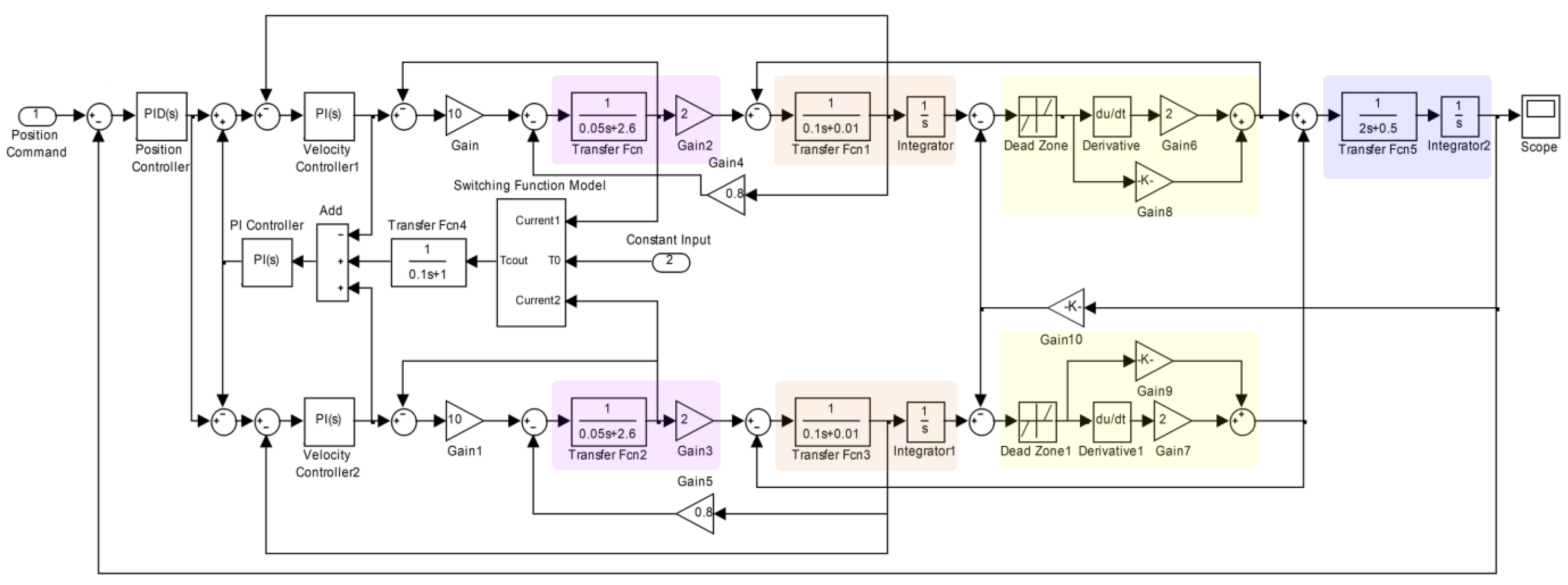
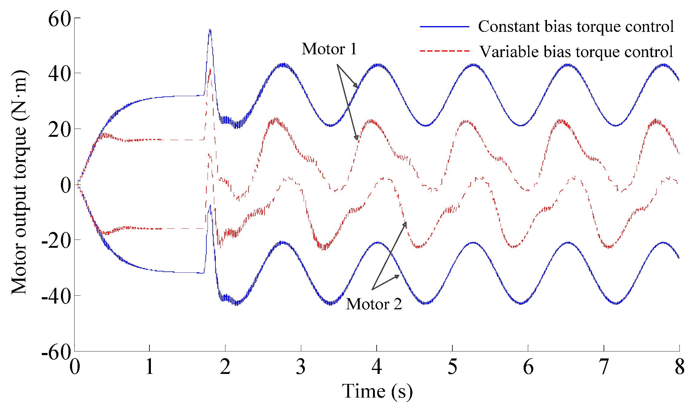
3.2. Simulation of the Backlash Elimination Performance

The backlash elimination process of the dual–motor drive system is complicated, and the variable bias torque backlash elimination control method is verified by establishing the simulation model of the dual–motor drive system in MATLAB/Simulink in this section. The simulation parameters are set as follows: armature winding resistance R = 2.6 Ω, armature winding inductance L = 0.05 H, motor torque coefficient Kd = 1.066 (Nm/A), motor counter potential coefficient Ke = 0.8 (V·rad−1·s), motor equivalent rotational inertia Jm = 0.1 (kg·m2), motor–side viscous friction coefficient bm = 0.01 (N·m·rad−1·s), load equivalent rotational inertia Jb = 2 (kg·m2), load equivalent viscous friction coefficient bb = 0.5 (N·m·rad−1·s), elasticity coefficient ks = 6 × 10⁵ (Nm·rad−1), damping coefficient cs = 2 (N·m·rad−1·s), gear backlash 2α = 0.02 rad, and gear ratio μ = 10. The system adds separate low–pass filters to the current detection side to eliminate noise interference, respectively, with the current filter coefficient k1 = k2 = 10. The simulation model of the dual–motor drive system is shown in Figure 8.
The simulation process makes the following assumptions: (1) the parameters of the two servo systems are nearly the same, and (2) the pinion gear is not in contact with the large gear at the initial moment (t = 0). The rated torque of the DC motor in the simulation is 30 Nm, and 10% of the rated torque is used as the elimination gap compensation torque, which means the maximum bias torque between motors is about 6 Nm, and the corresponding constant compensation voltage is about Uconst = 3 V. According to the current setting value calculation method in Section 2.3, we obtain iset1 = 2 A and iset2 = 3 A.
Firstly, we verify the stability of the control system using the root locus method. The dual–motor cross–coupled control block diagram can be represented as shown in Figure 9. Gvc (s) represents the speed loop PI controller, Gcb (s) represents the current loop, GL (s) represents the transfer function from motor load torque to the output speed, and T represents the motor load torque.
G v c ( s ) = K vp ( 1 + K vi s )
where Kvp and Kvi represent the speed control proportional and integral coefficients.
G cb ( s ) = K cp L T o s 2 + L s + K cp
where Kcp represents the current control proportional coefficients, and To represents the current control cycle.
G L ( s ) = 1 J λ s
From Equations (23)–(25), the transfer function of the single motor control system can be expressed as
n λ = K d λ G v c ( s ) G c b ( s ) G L ( s ) 1 + K d λ G v c ( s ) G c b ( s ) G L ( s ) n * G L ( s ) 1 + K d λ G v c ( s ) G c b ( s ) G L ( s ) T L λ
where n* represents the reference speed, and nλ represents the output of the λth motor.
In order to analyze the stability of the cross–coupled control, the cross–coupled part in Figure 9 is equivalent to a closed–loop control Gequ1, whose transfer function is expressed as Equation (27), where λ = 1, 2, κ = 1, 2, and the velocity output of the cross–coupled control system after the equivalence is as shown in Equation (28).
G e q u λ = G v c ( s ) G c b ( s ) 1 + C G v c ( s ) G c b ( s ) G λ λ = K d λ G e q u λ G L 1 + K d λ G e q u λ G L G λ κ = K d λ G L 1 + K d λ G e q u λ G L
n 1 = G 11 n * + G 12 ( C n 2 G L K d λ 1 K d λ G c b T L 1 ) n 2 = G 21 n * + G 22 ( C n 1 G L K d λ 1 K d λ G c b T L 2 )
Substituting the output velocity n2 of the slave axis in Equation (28) into the output velocity n1 of the master axis can be further simplified to obtain Equation (29).
n 1 = G 11 + C G 12 G 21 1 C 2 G 12 G 22 n * C G 12 G 22 1 K d G c b 1 C 2 G 12 G 22 T L 2 G 12 1 K d G c b 1 C 2 G 12 G 22 T L 1
The cross–coupled parameter root locus of the system can be derived on the basis of Equation (29). Firstly, the characteristic polynomial of the closed–loop transfer function is derived, and the term containing the parameter C is extracted as the numerator, which is denoted as the num term in Equation (30), and all the rest of the terms are used as the denominators, which are denoted as the den term in Equation (30), to construct the equivalent open–loop transfer function with the same poles G0 (s), and ultimately, the trajectory of the characteristic root of the system can be obtained. The simulation parameters are substituted into Equation (30), and the root trajectory is plotted by MATLAB, as shown in Figure 10. It can be seen that the system is stable when the cross–feedback gain value C is in the range of 0 to 3.
n u m = a 0 s 2 ( ( b 13 + b 23 ) s 3 + ( b 12 + b 22 ) s 2 + ( b 11 + b 21 ) s ) + 2 a 0 2 ( c 1 s 2 + c 2 s ) d e n = s 2 ( b 13 s 3 + b 12 s 2 + b 11 s ) ( b 23 s 3 + b 22 s 2 + b 21 s ) + a 0 ( c 1 s 2 + c 2 s ) ( ( b 13 + b 23 ) s 3 + ( b 12 + b 22 ) s 2 + ( b 11 + b 21 ) s ) + a 0 2 ( c 1 2 s 2 + c 2 2 + 2 c 1 c 2 s ) G 0 ( s ) = n u m d e n C
where a0 = KKcp, b11 = KcpJ1, b12 = KcpJ1, b13 = LT0J1, b21 = KcpJ2, b22 = LJ2, b23 = LT0J2.
Then, the effectiveness of the backlash elimination method is verified by the sinusoidal response. The sinusoidal response input is the sinusoidal position command signal of amplitude 1 rad and angular frequency 5 (rad·s−1). The sinusoidal response curve of the system is shown in Figure 11. The tracking error curve shown in Figure 12 shows that when the bias torque is not loaded, the tracking error fluctuates greatly and affects the trajectory tracking accuracy due to the influence of the gear backlash, which makes the system change direction frequently to track the position command process, and the variable bias torque control eliminates the tracking error fluctuation caused by the transmission backlash.
Figure 13 shows the bias voltage output in the sinusoidal response. The maximum value of bias voltage is 3 V when the motor torque direction is changed; as the system has no backlash performance during the acceleration, the bias voltage can be reduced to 0, i.e., there is no bias torque effect between the two motors. Since there is a transition stage between backlash elimination control and torque synchronization control, the conversion process of a bias voltage between zero value and maximum value has no sudden change, which ensures the smoothness of bias torque loading between motors and proves that the conversion control is effective.
A comparison of the motor output torque is shown in Figure 14. When the sinusoidal response is driven in the forward direction, the forward output torque value by motor 1 decreases, while the torque of motor 2 is changed from the reverse of constant bias torque control to drive the load in the same direction as motor 1. The reverse drive is similar to the forward drive, which helps to improve the torque output capability of the dual–motor system. The torque values of both motors 1 and 2 are reduced under variable bias torque control, and the unnecessary antagonism between the motors is reduced, effectively reducing energy consumption.
A comprehensive analysis of the above shows that the variable bias torque backlash elimination control can convert the bias torque used for backlash elimination into the driving torque of the motor and enhance the torque output capability of the whole system without the system exhibiting backlash. In the stationary state, the bias torque of the system is reduced to a smaller value to achieve the purpose of reducing the energy consumption of the system.

4. Experimental Verifications

In the experiment, we first compare with the single motor gearing system containing backlash and illustrate the effectiveness of the backlash elimination method in this paper by comparing the positioning errors of the two systems. Then, the variable bias torque control method is compared with the constant bias torque control to illustrate the advantages of the proposed method in reducing energy consumption by comparing the motor currents and speeds under the same position command.

4.1. Description of Robot Joint Test Bench

The prototype of the dual–motor–driven robot joint was built, as shown in Figure 15. The robot joint is driven by two DC servo motors through the planetary reducer to drive the pinion gears, which drive the large gear and load through the pinion gears. The model of the DC servo motors and the load motor is MAXON RE25. The robot joint test bench is mainly composed of the computer, STM32F462 development board, DC power, drivers, and dual–motor–driven joint prototype, as shown in Figure 16. The hardware components and their relationship are shown in Figure 17. The computer downloads the program to the development board through the JLink emulator, and the USB is used in the serial port of the development board to communicate with the computer. The STM32 development board is programmed using Keil5.35 software. The servo driver RMDS–301 is powered by a 24V DC power supply and communicates with the control board through the CAN bus to send motion commands to the DC motor and read the current, speed, and position information of the motor.
The technical parameters of the dual–motor–driven robot joint prototype are shown in Table 1.

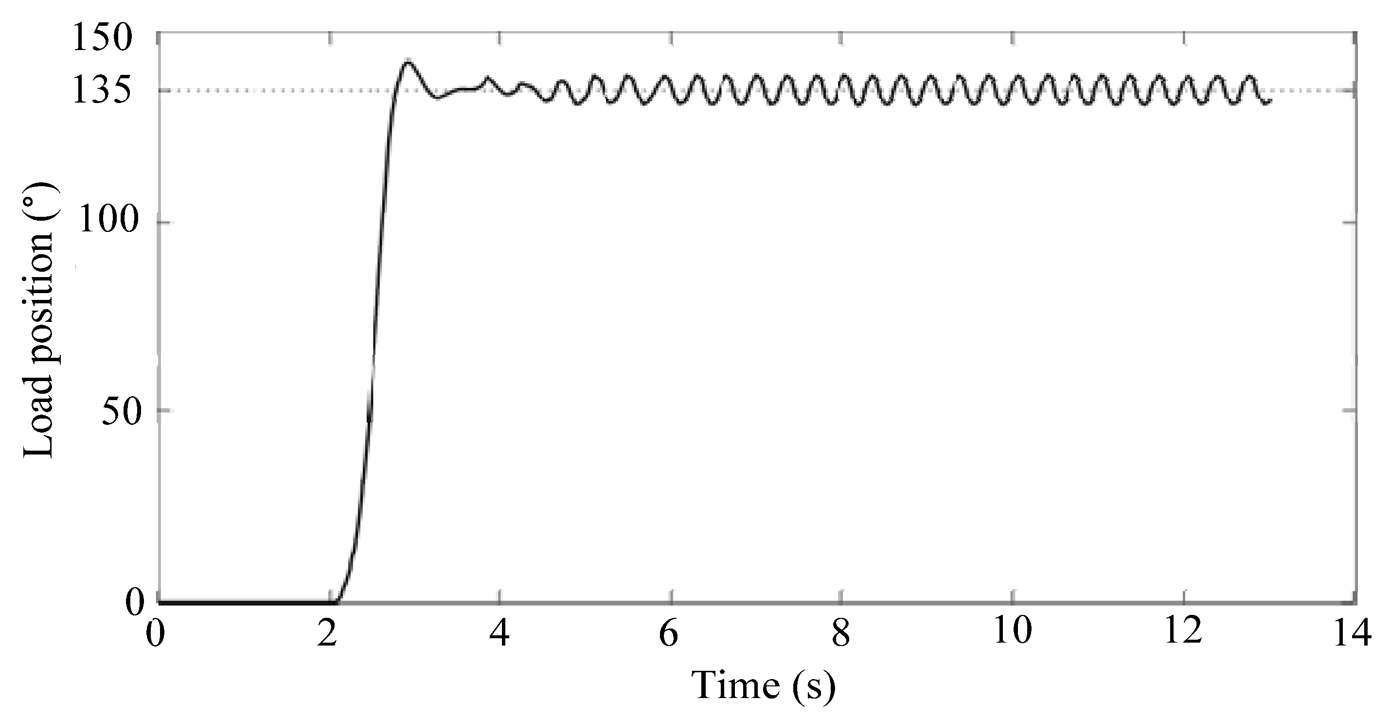
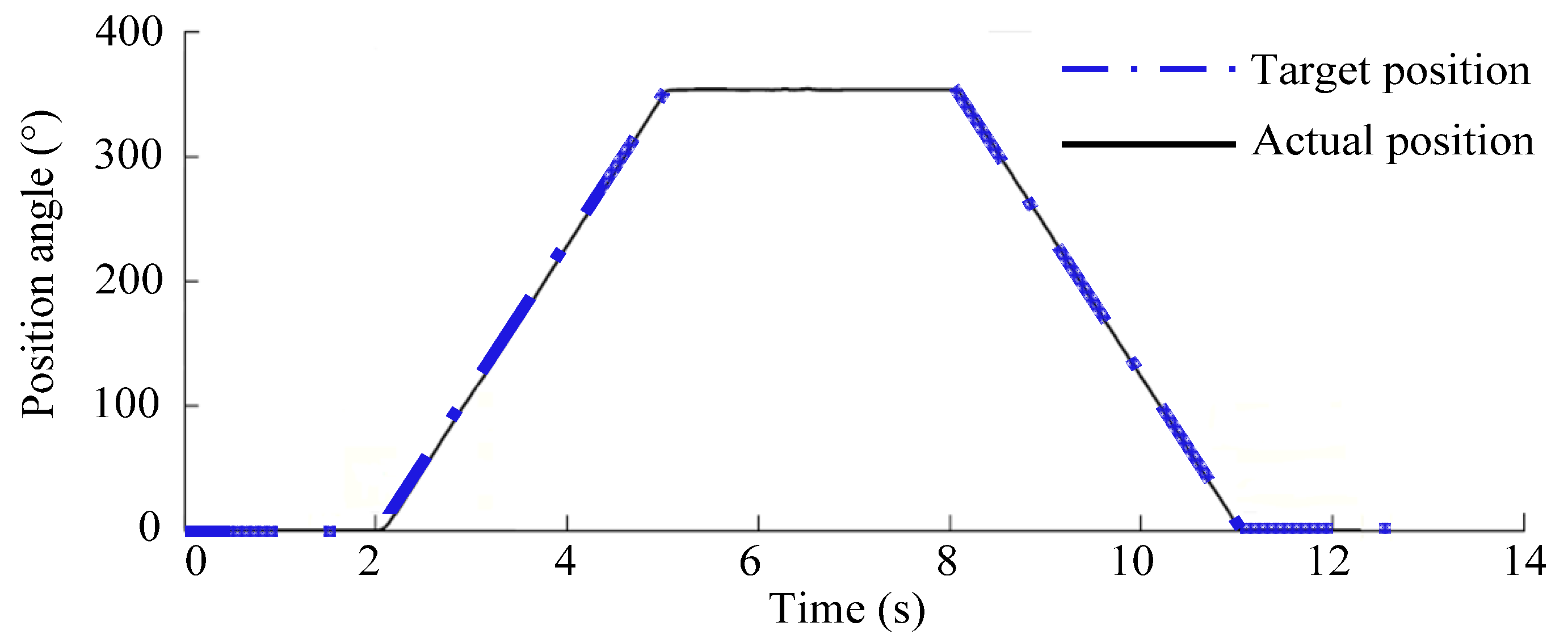
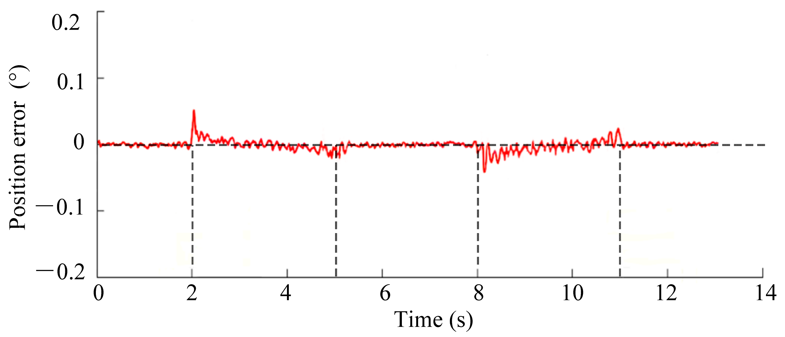
4.2. Results and Discussions

First, a single motor in the prototype is retained to drive the load, and the encoder at the load end is used to provide real–time feedback on the load’s rotational angle and speed. A 135° angle position step command is input to the system, and the angle position response curve at the load of the joint is obtained, as shown in Figure 18. From the position response curve, the servo system exhibits limit–loop oscillation near 135° at the output end because of backlash, and the oscillation amplitude is about 2° (gear backlash is about 2°). The gear backlash non–linearity has a large impact on both the motion accuracy and stability of the servo system [20].
In the dual–motor drive experiment, the joint was rotated 360° in the forward direction and then 360° in the reverse direction to show the actual effect of the backlash elimination control performance by the magnitude of the error in the rotation position of the robot joint prototype. According to the parameters of the dual–motor experimental system, the bias torque of the system is set to 5 (mN·m) (the bias torque is required to be larger than the friction torque), and the sampling period of the system is 8 ms. The rotational position response curve for the backlash elimination control is shown in Figure 19, and the rotational position error curve for the robot joint prototype is shown in Figure 20.
According to the response and error results of the robot joint prototype, the joint load side can quickly track the given position command under the action of the dual–motor variable bias torque backlash elimination control; in the experiment, the steady–state error of the servo system is less than 0.05°, and the error value of the joint commutation is much smaller than the internal backlash angle (about 2°) of the system, which indicates that the internal backlash of the robot joint has been eliminated. The experimental results show that the internal backlash of the robot joint drive system has been eliminated; the two–motor driven robot joint with variable bias torque backlash control can achieve good backlash elimination performance.
The corresponding motor speed and current variation curves during the servo response are shown in Figure 21 and Figure 22. From Figure 21, the rotational speeds of the two servo motors during the servo response are kept synchronized.
As can be seen from Figure 19, Figure 20, Figure 21 and Figure 22, the joint output remains stationary over 0–2 s, and the two motors enter into the backlash elimination control state by forming a bias torque between them, during which the bias current increases to the maximum value (about 250 mA) and then gradually decreases to about 110 mA, reducing the static energy consumption of the servo system effectively; over 2–5 s, the current of motor 1 increases positively as the forward ramp signal is given, and at the same time, the current of motor 2 decreases in reverse and then outputs positive current; that is, the two servo motors are converted from the backlash elimination control state to the common drive state, dragging the load to track the position command signal steadily at 120°/s, which effectively improves the driving capacity of the system. Within 5–8 s, the position command signal is 360°, and the dual–motor drive system is converted from the common drive state to the backlash elimination control state. Within 8–11 s, the dual–motor drive joint moves along the reverse ramp signal to the initial position point, and the dual–motor drive system converts from the backlash elimination control state to the common drive state, i.e., motor 1 starts to assist motor 2 to drive the load together. Within 11–13 s, the system returns to the stationary state, and the dual–motor system enters into the backlash control state from the common drive state again, and the backlash elimination control state maintains a smaller bias torque value.
In addition, in order to compare the motor torque (current) under variable bias torque control and constant bias torque control, the constant bias torque is next loaded on the dual–motor drive system, and the motor current variation curves of the system are obtained under the same control parameters and load conditions, as shown in Figure 23.
Compared with the currents in variable bias torque control, a constant backlash elimination bias torque is formed and maintained at a larger value from 0 to 2 s in the constant bias torque control; from 2 to 5 s, the current of the master motor 1 driving the load of the system increases positively, and the current of motor 1 is larger than the current of motor 1 under variable bias torque control at the same moment. Meanwhile, due to the presence of constant bias torque, motor 2 acts as a slave motor that does not drive the load together with the master motor. Within 5–8 s, the dual–motor drive system enters the constant bias torque control state. Within 8–11 s, motor 2 acts as the master motor to drive the load, and motor 1 acts as the slave motor and does not assist motor 2 to drive the load, resulting in the drive current of motor 2 being greater than the current value of motor 2 under variable bias torque control. Over 11–13 s, the system returns to the stationary state, and the dual–motor system enters the constant bias torque backlash elimination control state again.
According to the experiment results, the variable bias torque control can effectively improve the position accuracy of the drive system and give the dual–motor driven robot joint good backlash elimination performance. Compared with the constant bias torque control, the variable bias torque control can effectively reduce the energy consumption of a dual–motor drive system by switching between the backlash elimination control state and the common drive state, increasing the drive capability of the dual–motor system.

5. Conclusions

(1) The variable bias torque control loads a bias torque that varies directly according to the motor current, thus enabling variable bias torque backlash elimination control, and the setting method of the bias compensation torque is given in the article, which provides a reference for engineering applications.
(2) During the stationary state, the two motors enter a backlash elimination control state with a small bias torque, which reduces the static energy consumption of the servo system. During the common drive state, the slave motor starts to assist the master motor in driving the load together.
(3) The simulation results of the simulation model of the dual–motor drive system in MATLAB/Simulink and the experimental results of the backlash elimination control of the joint prototype show that the variable bias torque control can achieve a reasonable distribution of the output torque for the whole servo cycle and can effectively reduce the additional energy consumption of the system to maintain static backlash elimination. The dynamic loading of the bias voltage can be achieved through the setting of the conversion function to complete the smooth transition between the two states of backlash elimination control and common drive control, and the dynamic loading of the bias torque improves the torque output capability of the dual–motor system.

Author Contributions

Conceptualization, L.S.; methodology, L.S.; validation, L.S. and H.G.; formal analysis, L.S.; investigation, L.S. and H.G.; writing original draft, L.S.; visualization, L.S.; supervision, L.S.; project administration, L.S. and H.G. All authors have read and agreed to the published version of the manuscript.

Funding

This research was funded by the Liaoning Education Department General Project (JYTMS20230200) and the Liaoning Doctor Scientific Research Initial Fund (2021–BS–160).

Data Availability Statement

Data are contained within the article.

Conflicts of Interest

Author Longfei Sun was employed by the company Shenyang Ligong University Science and Technology development Corporation. The remaining author declare that the research was conducted in the absence of any commercial or financial relationships that could be construed as a potential conflict of interest.

References

  1. Gan, L.; Wang, L.P.; Huang, F. Adaptive backlash compensation for CNC machining applications. Machines 2023, 11, 193. [Google Scholar] [CrossRef]
  2. Gu, Y.K.; Li, W.F.; Zhang, J.; Qiu, G.Q. Effects of wear, backlash and bearing clearance on dynamic characteristics of a spur gear system. IEEE Access 2019, 7, 117639–117651. [Google Scholar] [CrossRef]
  3. Sun, L.; Li, X.X.; Chen, L.M.; Shi, H.; Jiang, Z.C. Dual–motor coordination for high–quality servo with transmission backlash. IEEE T. Ind. Electron. 2023, 70, 1182–1196. [Google Scholar] [CrossRef]
  4. Yang, X.; Lu, D.; Zhang, J.; Zhao, W.H. Analysis on steady–state vibration induced by backlash in machine tool rotary table. Proc. Inst. Mech. Eng. Part C J. Mech. Eng. Sci. 2017, 231, 4163–4171. [Google Scholar] [CrossRef]
  5. Shi, J.F.; Gou, X.F.; Zhu, L.Y. Modeling and analysis of a spur gear pair considering multi–state mesh with time–varying parameters and backlash. Mech. Mach. Theory 2019, 134, 582–603. [Google Scholar] [CrossRef]
  6. Zhang, H.; Wang, J.; He, G. A comparative investigation of meshing characteristics of anti–backlash single–and double–roller enveloping hourglass worm gears. J. Adv. Mech. Des. Syst. 2019, 13, 1–19. [Google Scholar] [CrossRef]
  7. Yu, L.; Wang, G.L.; Zou, S.D. The experimental research on gear eccentricity error of backlash–compensation gear device based on transmission error. Int. J. Precis. Eng. Man. 2018, 19, 5–12. [Google Scholar] [CrossRef]
  8. Wang, G.J.; Zhu, D.D.; Zou, S.D.; Jiang, Y.J.; Tian, X. Simulation and experimental research on electrical control anti–backlash based on a novel type of variable tooth thickness involute gear pair. Stroj. Vestn. J. Mech. Eng. 2022, 68, 26–140. [Google Scholar] [CrossRef]
  9. Li, F.J.; Wang, S.J.; Li, H. Backstepping integral nonsingular terminal sliding mode based fault–tolerant control of dual–motor synchronous anti–backlash servo system with extended state observer. In Proceedings of the 2021 China Automation Congress, Beijing, China, 22–24 October 2021; pp. 3831–3838. [Google Scholar]
  10. Xu, J.Q.; Fang, L.J.; Zhao, Q.K.; Wang, H.Z. Linear active disturbance rejection anti–backlash control for dual–motor coaxial driving robotic joint. In Proceedings of the 34th Chinese Control and Decision Conference (CCDC), Hefei, China, 15–17 August 2022; pp. 4289–4294. [Google Scholar]
  11. Qiu, X.B.; Cui, Y.Q.; Shan, D.S.; Zhang, C. Research on anti–backlash control strategy of asymmetric dual–motor driving system based on a small power auxiliary motor. In Proceedings of the 2017 International Conference on Computer System, Electronics and Control (ICCSEC), Dalian, China, 25–27 December 2017; pp. 174–177. [Google Scholar]
  12. Jiang, H.; Fu, H.Y.; Han, Z.Y.; Jin, H.Y. Elimination of Gear Clearance for the rotary table of ultra heavy duty vertical milling lathe based on dual servo motor driving system. Appl. Sci. 2020, 10, 4050. [Google Scholar] [CrossRef]
  13. Gawronski, W.; Beech–Brandt, J.J.; Ahlstrom, H.G.; Maneri, E. Torque–bias profile for improved tracking of the deep space network antennas. IEEE Antennas Propag. 2000, 42, 35–45. [Google Scholar] [CrossRef]
  14. Wu, J.F.; Zhang, R.; Yang, G.X. Design and experiment verification of a new heavy friction–stir–weld robot for large–scale complex surface structures. Ind. Robot 2015, 42, 332–338. [Google Scholar] [CrossRef]
  15. Zeng, T.; Ren, X.; Zhang, Y. Fixed–Time sliding mode control and high–gain nonlinearity compensation for dual–motor driving system. IEEE Trans. Ind. Inform. 2020, 16, 4090–4098. [Google Scholar] [CrossRef]
  16. Wang, C.; Yang, M.; Zheng, W.L.; Hu, K.; Xu, D.G. Analysis and suppression of limit cycle oscillation for transmission system with backlash nonlinearity. IEEE Trans. Ind. Electron. 2017, 64, 9261–9270. [Google Scholar] [CrossRef]
  17. Verl, A.; Engelberth, T. Adaptive preloading for rack–and pinion drive systems. CIRP ANN–Manuf. Techn. 2018, 67, 369–372. [Google Scholar] [CrossRef]
  18. Engelberth, T.; Neubauer, M.; Verl, A. Master–switch for electrically preloaded rack–and–pinion drives—Accuracy improvement of indirectly position controlled systems. ATP Mag. 2019, 3, 54–63. [Google Scholar] [CrossRef]
  19. Fan, G.L.; Tang, X.C.; Shen, Y.; Deng, L.N. Model predictive control method for multi–motor system with dead zone. In Proceedings of the 2021 6th International Conference on Automation, Control and Robotics Engineering, Dalian, China, 15–17 July 2021; pp. 333–337. [Google Scholar]
  20. Wang, B.; Iwasaki, M.; Yu, J. Command filtered adaptive backstepping control for dual–motor servo systems with torque disturbance and uncertainties. IEEE Trans. Ind. Electron. 2022, 69, 1773–1781. [Google Scholar] [CrossRef]
  21. Ren, H.P.; He, B. Anti–backlash control of machine tool feed system driven by dual motor. Electr. Mach. Control 2014, 18, 60–66. [Google Scholar]
  22. Robertz, S.G.; Halt, L.; Kelkar., S.; Nilsson, K.; Robertsson, A.; Schär, D.; Schiffer, J. Precise robot motions using dual motor control. In Proceedings of the 2010 IEEE International Conference on Robotics and Automation, Anchorage, AK, USA, 3–7 May 2010; pp. 5613–5620. [Google Scholar]
  23. Tian, G.; Gao, Z.H.; Liu, P.; Bian, Y.S. Dynamic modeling and stability analysis for a spur gear system considering gear backlash and bearing clearance. Machines 2022, 10, 439. [Google Scholar] [CrossRef]
Figure 1. Schematic diagram of dual–motor driving system structure.
Actuators 13 00291 g001
Figure 2. Block diagram of dual–motor variable bias torque control.
Actuators 13 00291 g002
Figure 3. The curve of the convert function.
Actuators 13 00291 g003
Figure 4. The flowchart of bias voltage calculation.
Actuators 13 00291 g004
Figure 5. The flowchart of MATLAB/Simulink modeling and simulation.
Actuators 13 00291 g005
Figure 6. Simplified model of dual–motor driving system.
Actuators 13 00291 g006
Figure 7. Structure block of dual–motor driving system.
Actuators 13 00291 g007
Figure 8. MATLAB/Simulink simulation model.
Actuators 13 00291 g008
Figure 9. Cross–coupled control block diagram.
Actuators 13 00291 g009
Figure 10. Root locus diagram.
Actuators 13 00291 g010
Figure 11. Sine response curves of dual–motor system.
Actuators 13 00291 g011
Figure 12. Tracking errors of sine response.
Actuators 13 00291 g012
Figure 13. Bias voltage output curve in sine response.
Actuators 13 00291 g013
Figure 14. Motor output torque curves of dual–motor system in sine response.
Actuators 13 00291 g014
Figure 15. Prototype of dual–motor drive robotic joint.
Actuators 13 00291 g015
Figure 16. Experimental platform of dual–motor drive robotic joint.
Actuators 13 00291 g016
Figure 17. Hardware composition.
Actuators 13 00291 g017
Figure 18. Step response curve of full closed–loop feedback position control.
Actuators 13 00291 g018
Figure 19. Angular response curve of the robotic joint.
Actuators 13 00291 g019
Figure 20. Position response error curve of the robotic joint.
Actuators 13 00291 g020
Figure 21. Angular velocities of motors using variable bias torque control. (a) Motor 1; (b) motor 2.
Actuators 13 00291 g021aActuators 13 00291 g021b
Figure 22. Currents of joint motors using variable bias torque control. (a) Motor 1; (b) motor 2.
Actuators 13 00291 g022
Figure 23. Currents of joint motors using the constant bias torque control. (a) Motor 1; (b) motor 2.
Actuators 13 00291 g023
Table 1. Technical parameters of robot joint prototype driven by dual–motor.
ParameterUnitValue
Rated power of motors 1 and 2W20
Rated speed of motors 1 and 2rpm8850
Rated torque of motors 1 and 2mN·m22.9
Armature inductance of motors 1 and 2mH0.115
Armature resistance of motors 1 and 2Ω1.33
Torque coefficient of motors 1 and 2mN·m/A16.3
Counter electromotive force coefficient of motors 1 and 2V/rpm0.0017
Equivalent moment of inertia of motors 1 and 2gcm210.49
Inertia of individual flywheelKgm27.75 × 10−3
The reduction ratio of reducers 1 and 266
Reduction ratio of backlash elimination unit2.8
Encoder resolution°0.09
Disclaimer/Publisher’s Note: The statements, opinions and data contained in all publications are solely those of the individual author(s) and contributor(s) and not of MDPI and/or the editor(s). MDPI and/or the editor(s) disclaim responsibility for any injury to people or property resulting from any ideas, methods, instructions or products referred to in the content.

