Article

Characterization of Friction within a Novel 3 mm Wristed Robotic Instrument

1
Department of Mechanical and Mechatronics Engineering, The University of Waterloo, Waterloo, ON N2L 3G1, Canada
2
Institute for Craniofacial and Cleft Innovation, Hospital for Sick Children, 555 University Ave., Toronto, ON M5G 1X8, Canada
3
Division of Plastic and Reconstructive Surgery, University of Toronto, 27 King’s College Circle, Toronto, ON M5S 1A1, Canada
*
Author to whom correspondence should be addressed.
Actuators 2024, 13(9), 326; https://doi.org/10.3390/act13090326
Submission received: 3 July 2024 / Revised: 16 August 2024 / Accepted: 21 August 2024 / Published: 27 August 2024
(This article belongs to the Section Actuators for Robotics)

Abstract

:
Surgical robotic tools are being developed for a variety of surgical procedures that are executed within small workspaces. Novel designs of miniaturized cable-actuated surgical tools for cleft palate repair have previously been developed. However, the behavior and significance of friction within these tools are largely unknown. A study was conducted to investigate the friction in a pulleyless 3 mm diameter wristed instrument. The wrist utilizes cable guide channels that allow for miniaturization at the cost of increased friction. An experimental rig was developed to measure friction within the wrist link mechanism when the tool is positioned at various pitch angles. A strong relationship between the cable tension and the tool’s pitch angle was found as a result of friction. The cable tension increased as the pitch angle approached extreme values (percent increases in the cable tension of 33% and 67.3% at a pitch of 90° and −90°, respectively). However, the resultant cable tension was below the failure strength of the cable, indicating that the design is feasible. The results of this study would be useful to those considering the design of miniature robotic surgical tools that are cable-driven. Significant tool reduction can be achieved by employing static guide channels for the cables, forgoing the use of additional moving components like pulleys while maintaining cable tension well within its break strength. Future work in the design and optimization of novel miniaturized wrist mechanisms should consider frictional effects and their impact on mechanism function.

1. Introduction

1.1. Motivation and Significance

Surgical robotic tools have undergone numerous developments since the 1980s. One of the most relevant surgical robotic systems is Intuitive Surgical’s (Sunnyvale, CA, USA) da Vinci surgical system [1]. The system utilizes tools with miniature wrists that can articulate within tight workspaces. These wrists allow for the performance of complex surgical tasks within operative spaces that may not be possible with traditional surgical instruments. Certain surgical procedures require even smaller instruments given their more constrained workspaces. Cleft palate repair is one such procedure that has been investigated as an opportunity to implement a robotic approach [2,3,4]. However, no such instruments have previously been developed that are optimized for the infant oral cavity workspace. This is due to the challenges of the further miniaturization of existing instrument wrist designs, which stem from the complexity and number of component parts, which impacts their manufacturability.
To address this, Podolsky et al. developed a compact pulleyless wrist with a diameter of 5 mm [5]. The design incorporates cable guide channels as opposed to pulleys.
These guide channels reduce the number and complexity of the component parts, allowing for further miniaturization. Furthermore, the integration of guide channels to replace pulleys minimizes the mechanism length, thus allowing for more compact articulation that is better suited for smaller workspaces. Wu et al. later improved this design by creating a more symmetric and smaller tool tip with a diameter of 3 mm [6] (Figure 1).
The existing literature emphasizes that friction is significant in cable-pulley-driven tools [7,8]. The newly developed cleft palate tools replace pulleys with these cable guide channels, making friction even more influential. During the development of the 5 mm wrist, Podolsky et al. investigated the dynamic friction caused by the main links of the tool. They found a maximum cable-tension increase of 97.7% at a 90° pitch [5]. This study also observed cable failure caused by the guide channels’ sharp edges.
To investigate the plausibility of the compact pulleyless 3 mm wrist, the frictional effects inherent in the design require exploration. This paper investigates the effects of dynamic friction in the two main links of the 3 mm wristed instrument developed by Wu et al. A description and illustration of the complete tool design, as well as detailed formulas and calculations to determine cable-path-length changes and corresponding cam profiles for the proposed pulleyless 3 mm tool design concept, can be found in [6].
The results of this study would be valuable to those engaged in robotic tool design for robotic-assisted surgical procedures that require reduced tool size. In particular, it would be useful to those considering a cable-driven, pin-jointed mechanism as it demonstrates that a pulleyless concept requiring cables sliding over fixed features as opposed to rolling over moving/rotating parts remains feasible by maintaining cable tension well within the cable’s break strength limit. In addition, the results indicate the magnitude of friction increases that one can expect at extreme wrist articulation where sharp bends are required in the actuating cables, relative to a neutral position with little-to-no bending. Future work will continue to validate this design concept further by employing the tools on cadavers and animal specimens.

1.2. Literature Review

Numerous studies have investigated friction in tendon-actuated surgical robotic instruments, mainly for the purposes of implementing friction-compensation subsystems or force feedback devices [7,9,10]. Do et al. used a modified LuGre model to create a dynamic friction model in arbitrarily shaped tendon-sheath mechanisms (TSMs) used in Natural Orifice Endoscopic Surgery (NOTES) [11]. They also designed and tested an adaptive controller for tendon-sheath mechanisms with a previously developed dynamic friction model [12]. The work in [9] goes on to devise a miniature sensor array to detect cable tension for a cable-driven parallel robot. The sensor output is then used in a force-compensation strategy to minimize the negative effects of friction and obtain more accurate force estimation.
The importance and utility of characterizing friction is also evident from works such as [13], where a model for closed-circuit cable-pulley-transmission robotic systems is developed to capture not only hysteresis effects due to cable stretch and material damping but also the friction in the entire cable-pulley network. Still, this model is intended for systems such as the RAVEN II (Applied Dexterity, Seattle, WA, USA) robotic surgery platform, which, like Intuitive’s da Vinci system tools, employ a conventional cable-driven design with cables running over rotating pulleys and idlers.
Palli et al. investigated TSM-driven robotic hands, first simulating Coulomb static friction and then simulating a dynamic friction model based on a lumped parameter tendon model [14]. Roy et al. presented a model that continuously estimates friction parameters and losses within a continuum surgical robotic tool [15]. Xue et al. considered cable-pulley systems in laparoscopic surgical robotic tools and proposed a model that accounts for the bending rigidity of the cable. They specifically studied applications where the cable radius is significant when compared to the pulley radius [8]. Miyasaka et al. investigated the effects of cable velocity, pulley quantity, and pulley size on Coulomb and viscous friction in the RAVEN II, a cable-pulley-driven surgical robotic platform [7]. In [16], a control method for tendon-sheath-actuation systems is developed using a friction model with compensation parameters. Here, the cable-bending angles are detected and compensated for in real time by employing an angle-identification model as well. The result was a significant improvement in response speed, force control accuracy, and overall system stability.
A unique friction-measuring method for cable-driven continuum manipulators using fiber Bragg grating sensors is presented in [17]. In addition to dynamic friction, the model also addresses static friction states where the direction of internal friction is unknown. Moreover, the method allows for the characterization of the friction distribution along the entire manipulator, which is necessary for continuum manipulators and remains an open research issue.
Numerous studies have used the Capstan equation to model friction in tendon-sheath mechanisms, which neglects cable rigidity [18,19,20]. However, Jung et al. concluded that cable rigidity cannot be ignored if the ratio between the radius of the cable and the radius of the body that the cable wraps around is less than 100 [21]. In the 3 mm cleft palate tool, this ratio is well below 100. Consequently, the friction in these compact cleft palate tools most likely cannot be modeled like tendon-sheath mechanisms or cable-pulley-system instruments.
A considerable amount of research has been conducted to investigate and correct frictional effects in surgical robotic tools that use tendon-sheath mechanisms, cable-actuated continuum wrists, and cable-pulley systems. On the other hand, little research has been conducted to characterize friction in highly compact, pin-jointed end-effectors.
Podolsky et al. conducted early friction tests on the initial 5 mm tool tip wrist mechanism developed for cleft palate repair and found the effects of friction to cause cable-tension increases as high as 97.7% [5]. Wu et al. discussed the role of friction and the potential for friction compensation in the 3 mm tool but did not conduct tests to quantify its significance [6].
This paper experimentally characterizes the friction between the end-effector links and the actuation cable of the 3 mm wrist. This work can provide foundational knowledge for future developments of miniaturized pulleyless pin-jointed wrist mechanisms. This will aid in the advancement of smaller surgical robotic tools that are more suitable for tasks performed in small workspaces, such as cleft palate repair.

2. Materials and Methods

2.1. Experiment Setup

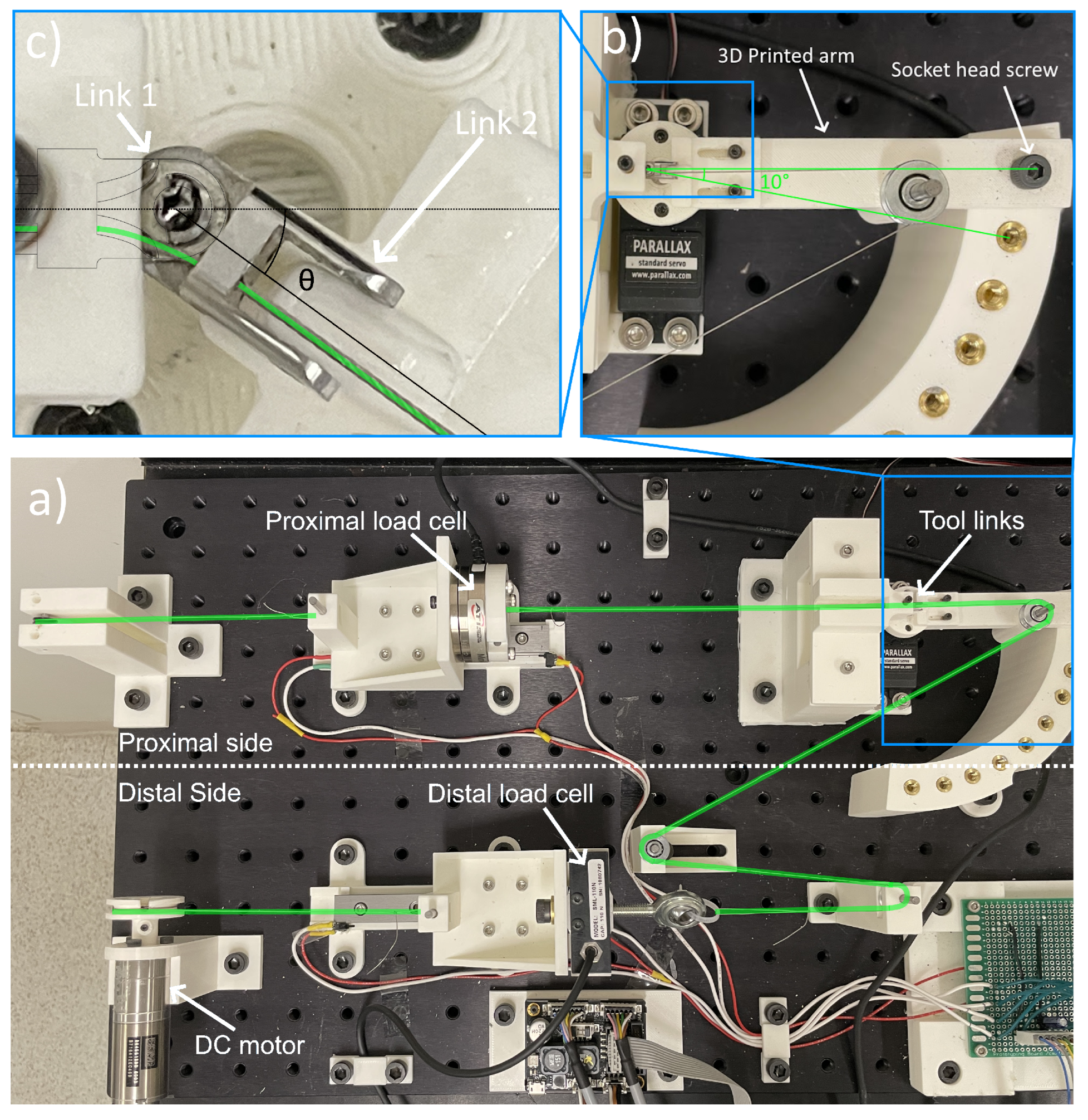
An experimental rig (Figure 2) was developed to measure cable tension during the pitching motion of link 2 relative to link 1 of the 3 mm wrist (Figure 1 and Figure 3). This allowed for the determination of the frictional effects of the guide channels of link 1. On the distal side of the wrist links, a DC motor pulls on one end of a carriage, which moves on a linear rail.
The distal load cell (SML low-height load cell, Interface Force Measurement Solutions, Scottsdale, AZ, USA) is rigidly attached to the proximal end of the distal carriage. On the proximal side of the links, a 150-gram payload pulls the proximal carriage on a linear rail. The proximal load cell (ATI mini40, ATI Industrial Automation, Apex, NC, USA) is attached to the distal end of the carriage. Through a series of pulleys, a stainless steel cable is connected to the two load cells. This cable runs along the guide channels of link 1 and link 2 (Figure 2), representing the actuation cable of the instrument. The cable used is a 0.2286 mm ( 0.009 ) 7 × 7 core stranded stainless steel cable (Carl Stahl Sava Industries, Inc., Riverdale, NJ, USA).
The motor turns at a constant angular velocity through open-loop angular speed control using an off-the-shelf motor controller and the motor’s built-in encoder. An angular speed set-point of 60 rpm was used, resulting in a steady-state cable speed of 4.2 mm/s, which conveniently allowed for 60-second-long trials during experimentation. The load cells measured the cable’s tensions at the distal and proximal sides of the tool links. Link 1 was fixed while link 2 was pitched relative to link 1. The links used in this experiment underwent minor design changes to the mechanism described by Wu et al. [6]. This allowed for fabrication using computer numerical control (CNC) techniques as opposed to direct metal laser sintering (DMLS). These design changes include removing thin edges and unnecessary fillets, straightening through-holes to avoid bent channels, and removing part of the center groove (Figure 4). The links were machined from 316 stainless steel with a deburred finish, resulting in smoother parts. Figure 5 shows an exploded view of the 4 links that make up the wrist mechanism (with a needle-driver tip), with annotations indicating the 4 DOFs.

2.2. Data Collection and Processing

To simulate the tool tip at various pitch angles, link 2 was manually rotated from −90° to 90° by increments of 10°. Link 2 was fixed to a three-dimensionally (3D) printed arm. Both link 2 and the arm pivoted relative to link 1. The other end of the arm was clamped to a support block using a socket head screw. The support block contained threaded inserts arranged in a circular pattern with 10° between adjacent inserts (Figure 2). For each pitch angle, five trials of the experiment were run. Each trial lasted 60 s, with a sampling rate of at least 34 samples per second.
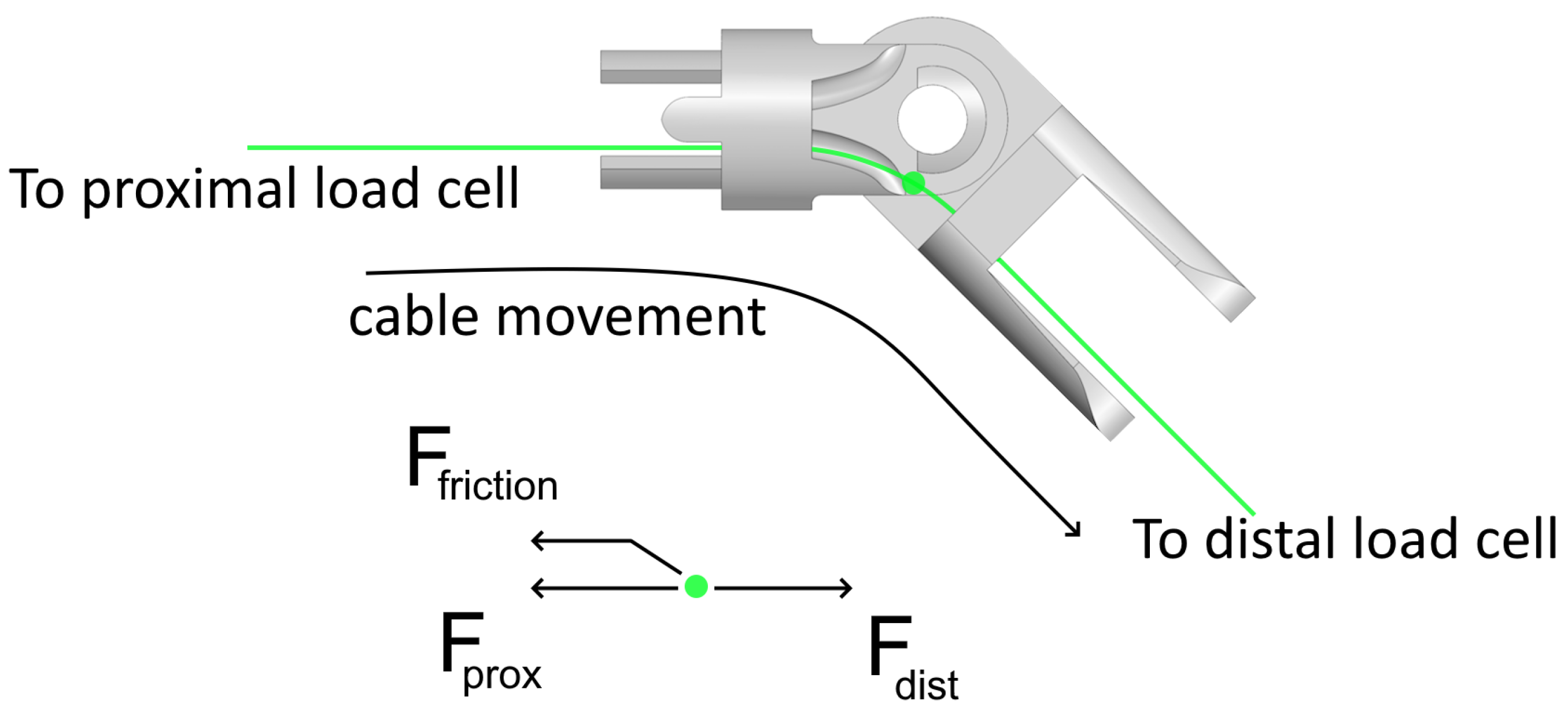
The distal and proximal load cells measured the cable tension before and after the links. Data from the proximal load cell (ATI Mini40) were acquired via a National Instruments DAQ and PCI processing board, while the data from the distal load cell (SML-110N) were passed into a Futek (FUTEK Advanced Sensor Technology, Inc., Irvine, CA, USA) DAQ. The raw data from both DAQs were then fed to the main controller PC, which filtered the data in software through a Matlab low-pass filtering script. The data collected during cable acceleration were identified visually from plots of the raw data and removed manually from the data set during post-processing. Friction was determined by subtracting the proximal from the distal cable tension, as per Figure 6 and Equation (1). The average friction for each pitch angle was then calculated:
F f r i c t i o n = F d i s t F p r o x

3. Results

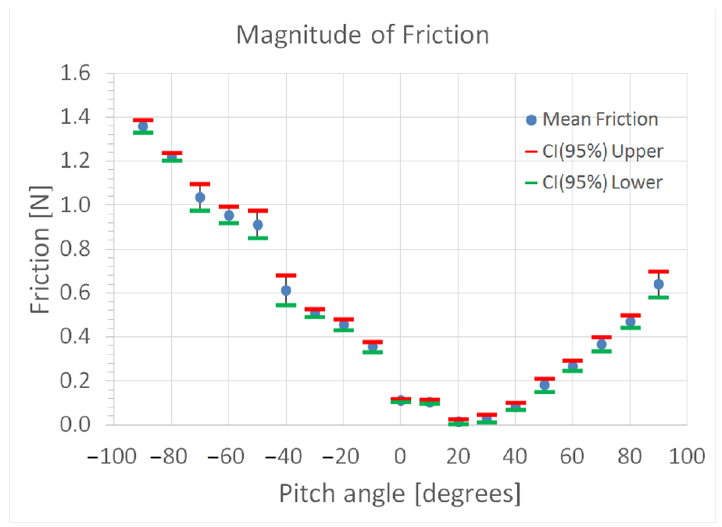
The average magnitude of friction as a function of pitch follows an asymmetric parabolic shape (Figure 7) with a minimum of 0.02 N at a pitch angle of 20°. The maximum friction occurred at −90° with a magnitude of 1.4 N. This peak friction was approximately 93% of the applied load.
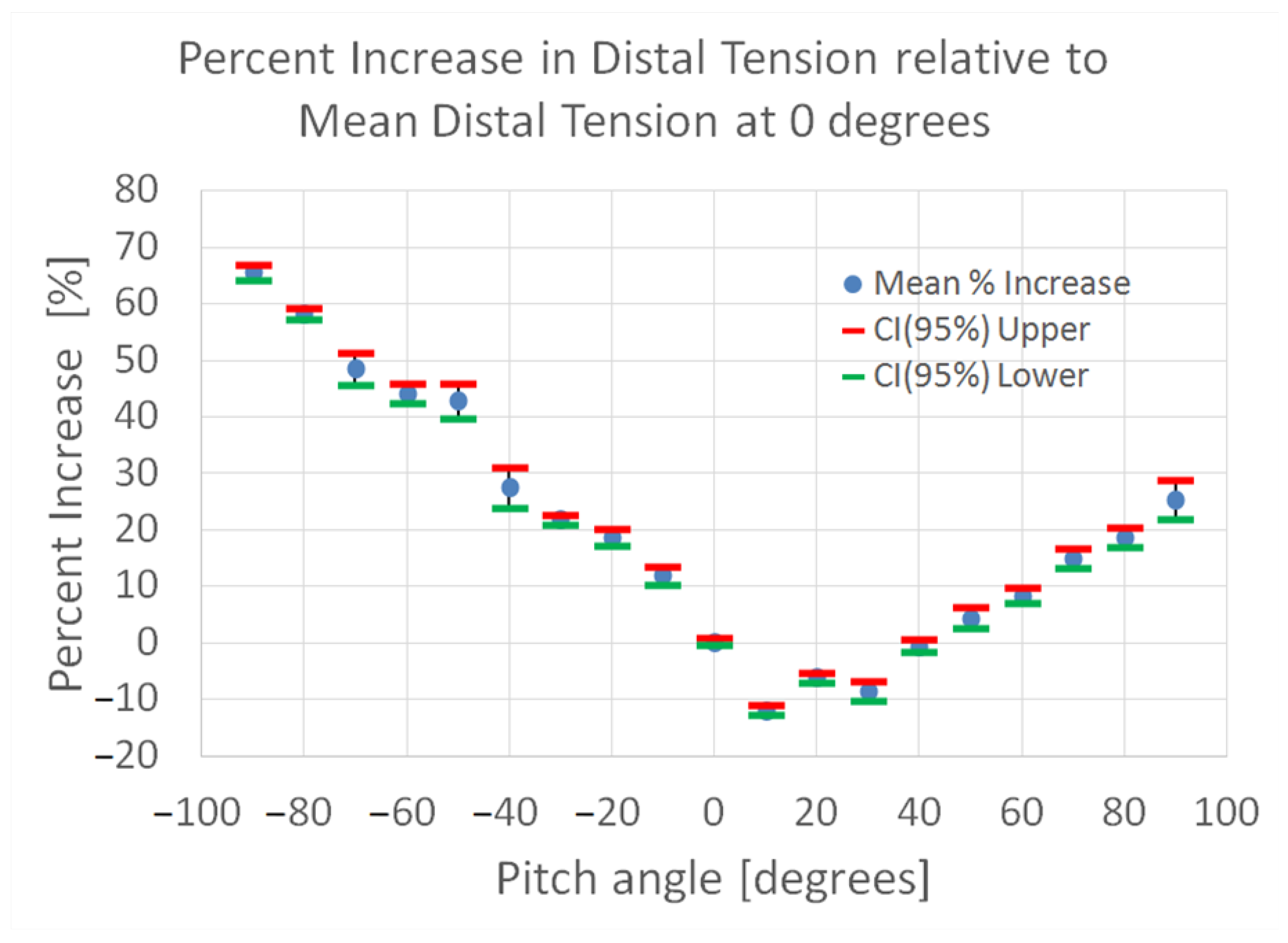
Figure 8 shows the percentage change in friction at different pitch angles relative to the friction at the neutral position (i.e., pitch = 0°). A similar parabolic trend can be observed in this plot as well. The maximum percent increase (67.3%) in cable tension also occurred at −90°. It should be noted that the cable tension for pitch angles between 0° and 40° is lower than that at neutral since the cable lifts off the central guide channel within this pitch range, resulting in a lower surface area of the contact between the cable and the links. As such, the percentage increase in cable tension is negative in this range.

4. Discussion

4.1. Significance of Friction

Both friction and cable tension increased during pitch following an asymmetric parabolic shape. This trend corresponded with the geometry of the links. At 20°, there is minimal contact area between link 1 and the cable. At −90°, the cable wraps around most of the center groove, maximizing the contact area and resultant friction magnitude (Figure 9). The 95% confidence intervals for the friction measurements as well as the percent increase in distal tension measurements at each pitch angle setting show narrow ranges, with the largest being 0.14 N and 7.03%, respectively. This indicates good precision and low margins of error, thereby validating the average values computed and the overall trend observed.
In addition, the friction magnitude for negative pitch angles followed a steeper rate of change in comparison to positive pitch angles.
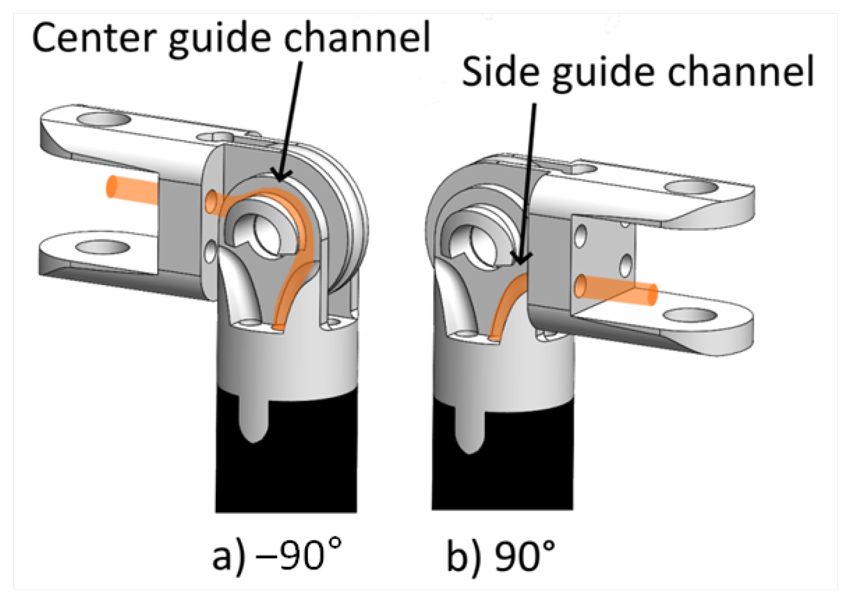
This can be attributed to the geometric asymmetry of link 1 relative to each cable path during pitch. For negative pitch, the cable wraps around the center guide channel that has a radius of 0.77 mm. For positive pitch angles, the cable follows a non-circular side guide channel with a larger bending radius (Figure 10).
With a maximum increase in cable tension of 67.3%, the friction in the linkages is substantial and is an important consideration for mechanisms that omit friction-reducing features such as pulleys to aid in miniaturization. Since the increase in cable tension follows a trend (parabolic as a function of pitch), there is potential to implement a friction-compensation mechanism in future systems. Although the friction between the wrist links and cable increased substantially during wrist pitch, the maximum friction and resultant cable-tension increase falls well below the failure strength of the cables.
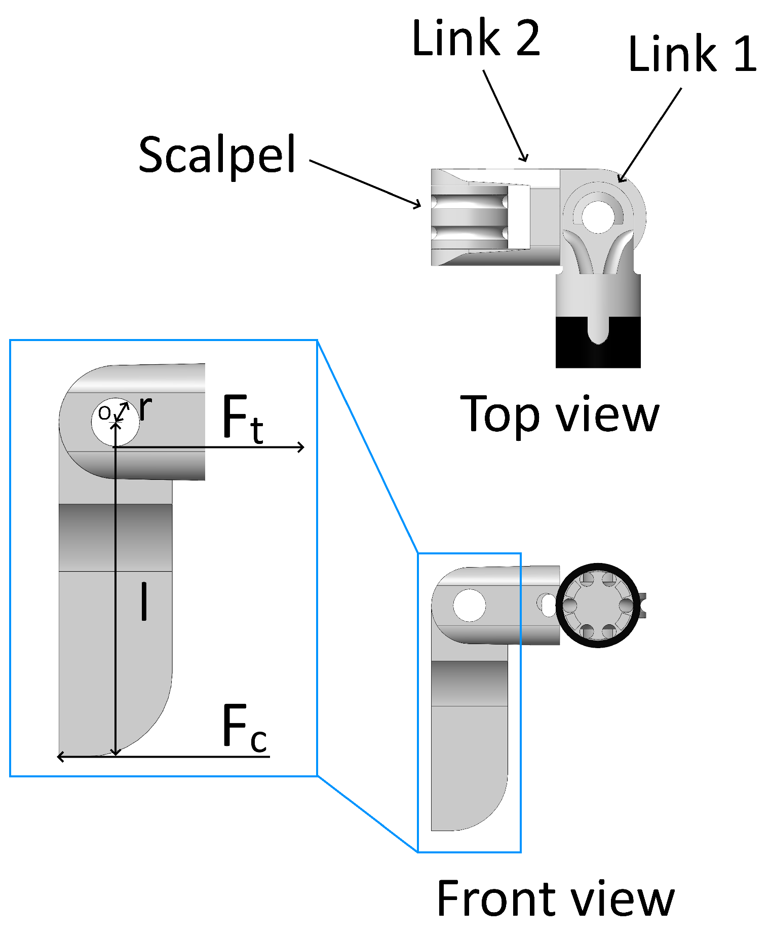
Sorouri et al. reported a peak cutting force of 10.27 N when cutting porcine hard palate mucosa [22]. To calculate the resultant cable tensions in the 3 mm tool, consider the scenario in which the tool experiences the largest cutting force (Figure 11). The free-body diagram depicts the scalpel geometry ( r , l ), cutting force ( F c ), and the tension in each cable needed to resist the cutting force ( F t ). These calculations assumed a scalpel tool whose geometric dimensions are outlined in Table 1. A moment equilibrium was applied at point O to find the tension in each cable (Equation (2)). The 3 mm tool utilizes two cables. Consequently, each cable resists half the total cutting force.
Σ M O = 1 2 F c · l F t · r 0 = 1 2 F c · l F t · r F t = 1 r 1 2 F c · l F t = 30.24 N
Applying the maximum increase in cable tension of 67.3% to the calculated cable tension yields a final tension of 50.59 N (30.24 × 1.673). The cable has a breaking strength of 66 N [23], resulting in a safety factor of 1.3.
It should also be noted that the average force needed to cut porcine hard palate mucosa ranges from 0.98 to 3.30 N. The force required to cut porcine soft palate mucosa and muscle falls below this range [22], further increasing the safety factor. Finally, this study used pig palatal tissue that is thicker than human infant palatal tissue. As such, the forces required during cleft palate surgery in human infants are likely less than the values reported by Sorouri et al. Thus, the implementation of the cable guide channels to aid in miniaturization and to increase the compactness of articulation by decreasing the mechanism length is a plausible design feature.

4.2. Comparing the 3 mm Tool with the 5 mm Tool

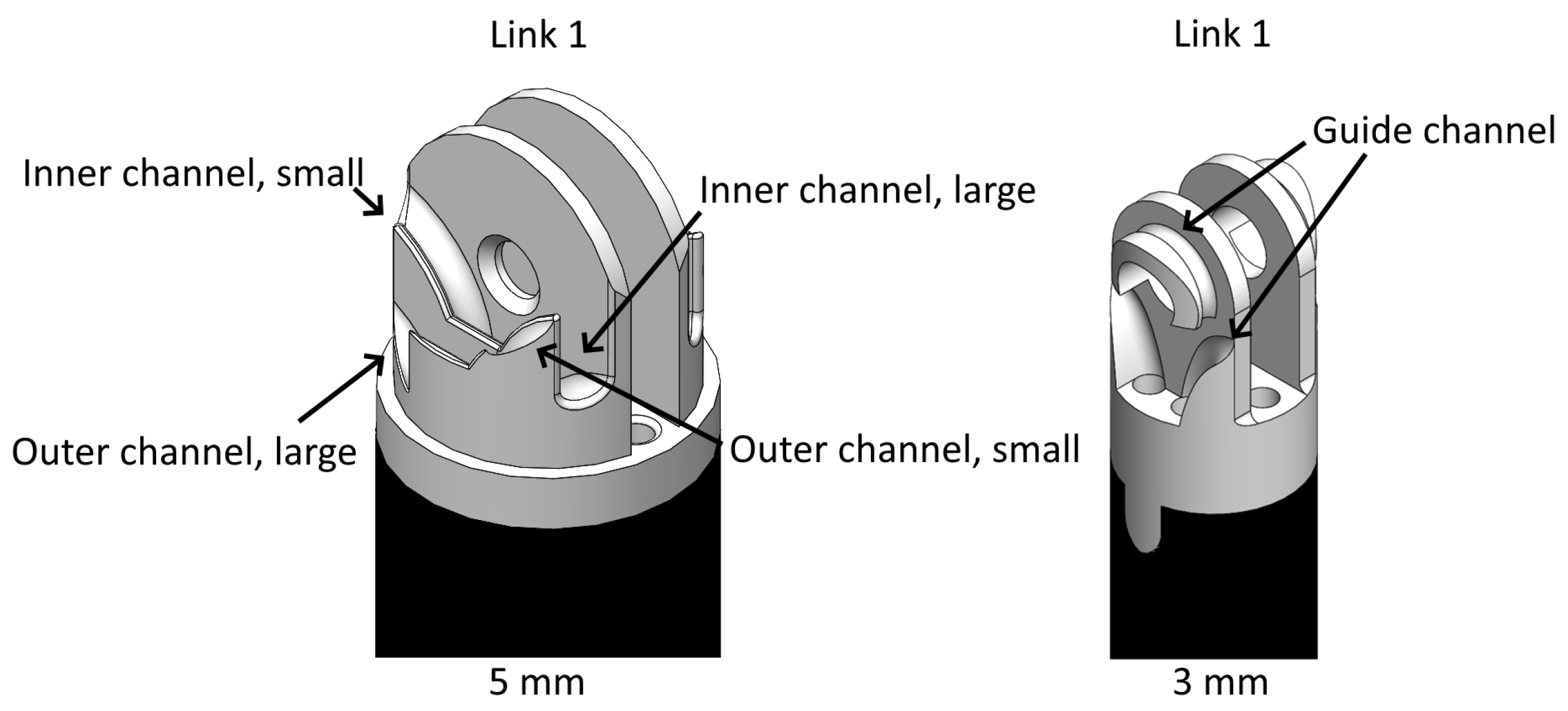
Table 2 outlines the parameters of the friction analysis of the 5 mm tool from Podolsky et al. [5] and the parameters used in this experiment. The main difference between the 5 mm and 3 mm tools is their geometric design. The 5 mm tool features more complex and asymmetric cable routes and four unique guide channels compared to the 3 mm tool that has two unique channels (Figure 12).
It should be noted that the outer small channel in the 5 mm design could not be tested because its sharp edges frayed and eventually cut the cable [5]. In contrast, the 3 mm links never caused cable failure. The 5 mm tool exhibited a maximum cable-tension increase of 97.7% at a pitch angle of 90° [5]. On the other hand, the 3 mm links produced a maximum cable-tension increase of 67.3% at a pitch angle of −90°.
Therefore, the 3 mm tool outperformed the 5 mm tool by providing reduced friction as well as a simpler and more compact design. Furthermore, the 3 mm tool eliminated cable fraying or snapping during testing. In addition to the different geometric designs of the 5 and 3 mm wrists, differences in surface roughness as a result of the different material and production methods of the two mechanisms is a significant factor. The 5 mm tool was 3D printed in 17-4PH stainless steel using DMLS, whereas the 3 mm tool was CNC machined out of 316 stainless steel and further smoothed via deburring.

4.3. Limitations of Study

The linear rails and pulleys used in the experimental setup contribute to the overall increase in cable tensions. The magnitude of the frictional effects of these components was determined to be 0.002 N, which is negligible relative to the cable-tension increases from the guide channels.
The force required to cut porcine palatal tissue at reasonable cutting angles can reach 10 N [22]. This study used a 150-gram (1.47 N) payload to simulate cable tension. Future work should be conducted to investigate higher magnitudes of friction at cable tensions that may be encountered during soft tissue procedures such as cleft palate repair.

4.4. Significance of Cable Wear

The worn cable yielded friction magnitudes nearly double that of the unused cable. The worn cable was observed to easily develop kinks and deform when slack. These kinks impact the ability of the cable to smoothly traverse along the link 1 guide channels and may increase the contact area between the cable and channel. This observation suggests that ongoing usage of the cable influences the magnitude of the frictional effects. A future study should investigate the impact of cable wear as well as fatigue. Although some robotic surgical tools have limited predetermined usages [24], cable wear may further shorten the life span of these tools.

5. Conclusions

The frictional forces of a pulleyless 3 mm wristed mechanism were characterized and found to increase during wrist pitch. However, the tension increases were below the failure thresholds of the cables. Therefore, although this 3 mm wrist design increased friction, it allows for miniaturization that would not be possible using pulleys. Furthermore, the change in friction with varying pitch angles follows a predictable parabolic trend, suggesting the possibility of implementing friction-compensation techniques such as model-based feedforward loop control. When comparing the 3 mm and 5 mm wrist design, not only does the 3 mm tool offer a more compact design, but the frictional effects in the 3 mm tool are smaller, owing to the smoother CNC-machined guide channels compared to those of the metal 3D-printed links of the 5 mm design. As such, future work is recommended to continue the development of the 3 mm tool as a viable design for the development and implementation of miniaturized wrist mechanisms.

Author Contributions

Conceptualization, C.H., T.L., G.M., and D.J.P.; methodology, C.H., T.L. and D.J.P.; software, C.H.; validation, C.H.; formal analysis, C.H., T.L. and G.M.; investigation, C.H.; resources, T.L. and D.J.P.; data curation, C.H.; writing—original draft preparation, C.H. and T.L.; writing—review and editing, C.H., T.L., G.M. and D.J.P.; visualization, C.H.; supervision, T.L. and D.J.P.; project administration, T.L. and D.J.P.; funding acquisition, T.L. and D.J.P. All authors have read and agreed to the published version of the manuscript.

Funding

This research was funded by grant number 6210101144 from the Canadian Institutes of Health Research (CIHR).

Data Availability Statement

Dataset available on request from the authors.

Conflicts of Interest

The authors declare no conflicts of interest. The funders had no role in the design of the study; in the collection, analyses, or interpretation of data; in the writing of the manuscript; or in the decision to publish the results.

References

  1. George, E.I.; Brand, C.T.C.; LaPorta, R.A.; Satava, J.M.C.R.R.M. Origins of Robotic Surgery: From Skepticism to Standard of Care. J. Soc. Laparosc. I Robot. Surg. 2018, 22, e2018.00039. [Google Scholar] [CrossRef] [PubMed]
  2. Podolsky, D.J.; Fisher, D.M.; Wong Riff, K.; Looi, T.; Drake, J.; Forrest, C.R. Infant Robotic Cleft Palate Surgery: A Feasibility Assessment Using a Realistic Cleft Palate Simulator. Plast. Reconstr. Surg. J. Am. Soc. Plast. Surg. 2017, 139, 455–465. [Google Scholar] [CrossRef] [PubMed]
  3. Nadjmi, D.N. Transoral Robotic Cleft Palate Surgery. Cleft Palate Craniofacial J. 2016, 53, 326–331. [Google Scholar] [CrossRef] [PubMed]
  4. Khan, K.; Dobbs, T.; Swan, M.C.; Weinstein, G.S.; Goodacre, T.E. Trans-oral robotic cleft surgery (TORCS) for palate and posterior pharyngeal wall reconstruction: A feasibility study. JPRAS Int. J. Surg. Reconstr. 2016, 69, 97–100. [Google Scholar] [CrossRef] [PubMed]
  5. Podolsky, D.J. Development and Evaluation of a High Fidelity Cleft Palate Simulator for Surgical Training and for Development of a Robotic Approach to Infant Cleft Palate Surgery. Ph.D. Thesis, Institute of Biomaterials and Biomedical Engineering University of Toronto, Toronto, ON, Canada, 2017. [Google Scholar]
  6. Wu, G.C.Y.; Podolsky, D.J.; Looi, T.; Kahrs, L.A.; Drake, J.M.; Forrest, C.R. A 3 mm Wristed Instrument for the da Vinci Robot: Setup, Characterization, and Phantom Tests for Cleft Palate Repair. IEEE Trans. Med. Robot. Bionics 2020, 2, 130–139. [Google Scholar] [CrossRef]
  7. Miyasaka, M.; Matheson, J.; Lewis, A.; Hannaford, B. Measurement of the Cable-Pulley Coulomb and Viscous Friction for a Cable-Driven Surgical Robotic System. In Proceedings of the IEEE/RSJ International Conference on Intelligent Robots and Systems (IROS), Hamburg, Germany, 28 September–2 October 2015. [Google Scholar]
  8. Xue, R.; Ren, B.; Yan, Z.; Du, Z. A cable-pulley system modeling based position compensation control for a laparoscope surgical robot. Mech. Mach. Theory 2017, 118, 283–299. [Google Scholar] [CrossRef]
  9. Zhou, Z.; Yang, J.; Runciman, M.; Avery, J.; Sun, Z.; Mylonas, G. A Tension Sensor Array for Cable-Driven Surgical Robots. Sensors 2024, 24, 3156. [Google Scholar] [CrossRef] [PubMed]
  10. Do, T.N.; Tjahjowidodo, T.; Lau, M.W.S.; Phee, S.J. Dynamic Friction-Based Force Feedback for Tendon-Sheath Mechanism in NOTES System. Int. J. Comput. Electr. Eng. 2014, 6, 252–258. [Google Scholar] [CrossRef]
  11. Do, T.; Tjahjowidodo, T.; Lau, M.; Phee, S. A new approach of friction model for tendon-sheath actuated surgical systems: Nonlinear modelling and parameter identification. Mech. Mach. Theory 2015, 85, 14–24. [Google Scholar] [CrossRef]
  12. Do, T.N.; Tjahjowidodo, T.; Lau, M.W.S.; Phee, S.J. Performance Control of Tendon-Driven Endoscopic Surgical Robots with Friction and Hysteresis. arXiv 2017, arXiv:1702.02063. [Google Scholar]
  13. Miyasaka, M.; Haghighipanah, M.; Li, Y.; Matheson, J.; Lewis, A.; Hannaford, B. Modeling Cable-Driven Robot With Hysteresis and Cable–Pulley Network Friction. IEEE/ASME Trans. Mechatron. 2020, 25, 1095–1104. [Google Scholar] [CrossRef]
  14. Palli, G.; Melchiorri, C. Model and Control of Tendon-Sheath Transmission Systems. In Proceedings of the 2006 IEEE International Conference on Robotics and Automation, Orlando, FL, USA, 15–19 May 2006. [Google Scholar]
  15. Roy, R.; Wang, L.; Simaan, N. Modeling and Estimation of Friction, Extension, and Coupling Effects in Multisegment Continuum Robots. IEEE/ASME Trans. Mechantronics 2017, 22, 909–920. [Google Scholar] [CrossRef]
  16. Tan, K.; Shi, H.; Mei, X.; Geng, T.; Yang, J. Control of force transmission for cable-driven actuation system based on modified friction model with compensation parameters. Control. Eng. Pract. 2024, 151, 106035. [Google Scholar] [CrossRef]
  17. Dai, Y.; Wang, S.; Wang, X.; Yuan, H. A Novel Friction Measuring Method and Its Application to Improve the Static Modeling Accuracy of Cable-Driven Continuum Manipulators. IEEE Robot. Autom. Lett. 2024, 9, 3259–3266. [Google Scholar] [CrossRef]
  18. Agrawal, V.; Peine, W.J.; Yao, B. Modeling of Transmission Characteristics Across a Cable-Conduit System. IEEE Trans. Robot. 2010, 26, 914–924. [Google Scholar] [CrossRef]
  19. Kaneko, M.; Yamashita, T.; Tanie, K. Basic considerations on transmission characteristics for tendon drive robots. In Proceedings of the Fifth International Conference on Advanced Robotics ’Robots in Unstructured Environments, Pisa, Italy, 19–22 June 1991; Volume 1, pp. 827–832. [Google Scholar] [CrossRef]
  20. Chiang, L.S.; Jay, P.S.; Valdastri, P.; Menciassi, A.; Dario, P. Tendon Sheath Analysis for Estimation of Distal End Force and Elongation. In Proceedings of the 2009 IEEE/ASME International Conference on Advanced Intelligent Mechatronics, Singapore, 14–17 July 2009. [Google Scholar]
  21. Jung, J.H.; Pan, N.; Kang, T.J. Tension transmission via an elastic rod gripped by two circular-edged plates. Int. J. Mech. Sci. 2007, 49, 1095–1103. [Google Scholar] [CrossRef]
  22. Sorouri, K.; Podolsky, D.J.; Wang, A.M.; Fisher, D.M.; Wong, K.W.; Looi, T.; Drake, J.M.; Forrest, C.R. Utilization of a robotic mount to determine the force required to cut palatal tissue. J. Mech. Behav. Biomed. Mater. 2018, 86, 433–439. [Google Scholar] [CrossRef] [PubMed]
  23. Carl Stahl Save Industries Product Page: Stainless Steel Cable, Bare 7 × 7, Commerical. 2023. Available online: https://www.savacable.com/stainless-steel-cable-bare-7x7-commercial-1312 (accessed on 2 July 2024).
  24. Da Vinci X/Xi System Instrument and Accessory Catalog. 2023. Available online: https://www.intuitive.com/en-us/-/media/ISI/Intuitive/Pdf/xi-x-ina-catalog-no-pricing-us-1052082.pdf (accessed on 2 July 2024).
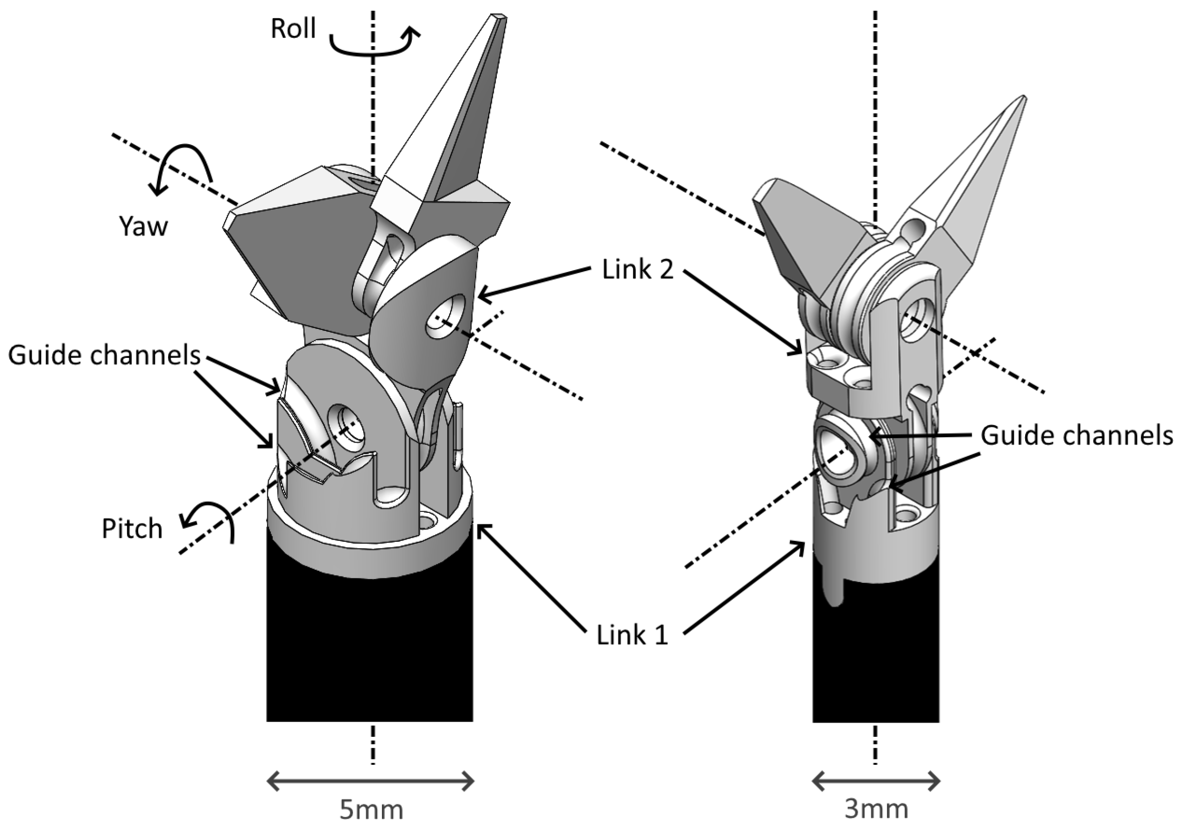
Figure 1. Cleft palate surgical tool pulleyless wrist designs: 5 mm (left) and 3 mm (right). Pitch, yaw, and roll axes are shown. Guide channels (highlighted) on link 1 reduce the length of the link, allowing for more compact articulation.
Actuators 13 00326 g001
Figure 2. (a) Experimental rig with key components labeled. Stainless steel cable paths highlighted in green. Two load cells measure the cable tensions on the distal and proximal sides of the tool links. The DC motor moves the system by pulling the distal carriage. A dead-weight payload hangs off the side of the rig to keep the cables in tension. (b) Mechanism used to set pitch angles of linkages. Link 2 pivoted with a 3D-printed arm. After the pitch was set, the arm was clamped to a support block by a socket head screw. The support block contained threaded inserts positioned in a circular pattern, each separated by 10° (green). (c) Links 1 and 2 assembled in the experimental rig. Theta represents the pitch angle. Thin black line for link 1 represents the remainder of the link obscured by the experimental rig.
Actuators 13 00326 g002
Figure 3. Link 1 and link 2 of 3 mm wrist at various pitches with cable paths highlighted in orange. (a) −90°, (b) 0°, (c) 90°.
Actuators 13 00326 g003
Figure 4. Design changes to original link 1 of 3 mm wrist. Changes include removing thin edges (yellow), fillets (green), and the bottom of the center guide channel (blue). Through-holes of the original link 1 were also straightened (not shown).
Actuators 13 00326 g004
Figure 5. Exploded view of wrist-mechanism links and the motions that make up the 4 DOFs (needle-driver-tool tip shown here as an example).
Actuators 13 00326 g005
Figure 6. Free-body diagram of link 1 and cable tensions used to determine the frictional effects of the cable guide channel.
Actuators 13 00326 g006
Figure 7. Change in friction magnitude with varying pitch angles.
Actuators 13 00326 g007
Figure 8. Percent change in distal side cable tension.
Actuators 13 00326 g008
Figure 9. Links 1 and 2 in the experimental rig at pitch angles −90° (left) and 0° (right).
Actuators 13 00326 g009
Figure 10. Link 1 and link 2 with center guide channel and side guide channels of link 1 highlighted in orange.
Actuators 13 00326 g010
Figure 11. Free-body diagram of a scalpel assembled with links 1 and 2 depicting the scalpel length (l), scalpel joint radius (r), force required to cut tissue ( F c ), and cable tension ( F t ).
Actuators 13 00326 g011
Figure 12. Link 1 of the 5 mm tool’s four unique guide channels (left). Link 1 of the 3 mm tool’s guide channels (right).
Actuators 13 00326 g012
Table 1. Parameters of cable-tension calculations.
ParameterValue
r1.35 mm
l7.95 mm
F c 10.27 N
F t 30.24 N
Table 2. Parameters of friction tests.
Parameter3 mm5 mm
Payload (g)150200
Cable diameter (mm)0.230.27
Max cable-tension increase (%)66.197.7
Links tested1.21
Disclaimer/Publisher’s Note: The statements, opinions and data contained in all publications are solely those of the individual author(s) and contributor(s) and not of MDPI and/or the editor(s). MDPI and/or the editor(s) disclaim responsibility for any injury to people or property resulting from any ideas, methods, instructions or products referred to in the content.