Characterization of Friction within a Novel 3 mm Wristed Robotic Instrument

Abstract
:1. Introduction
1.1. Motivation and Significance
1.2. Literature Review
2. Materials and Methods
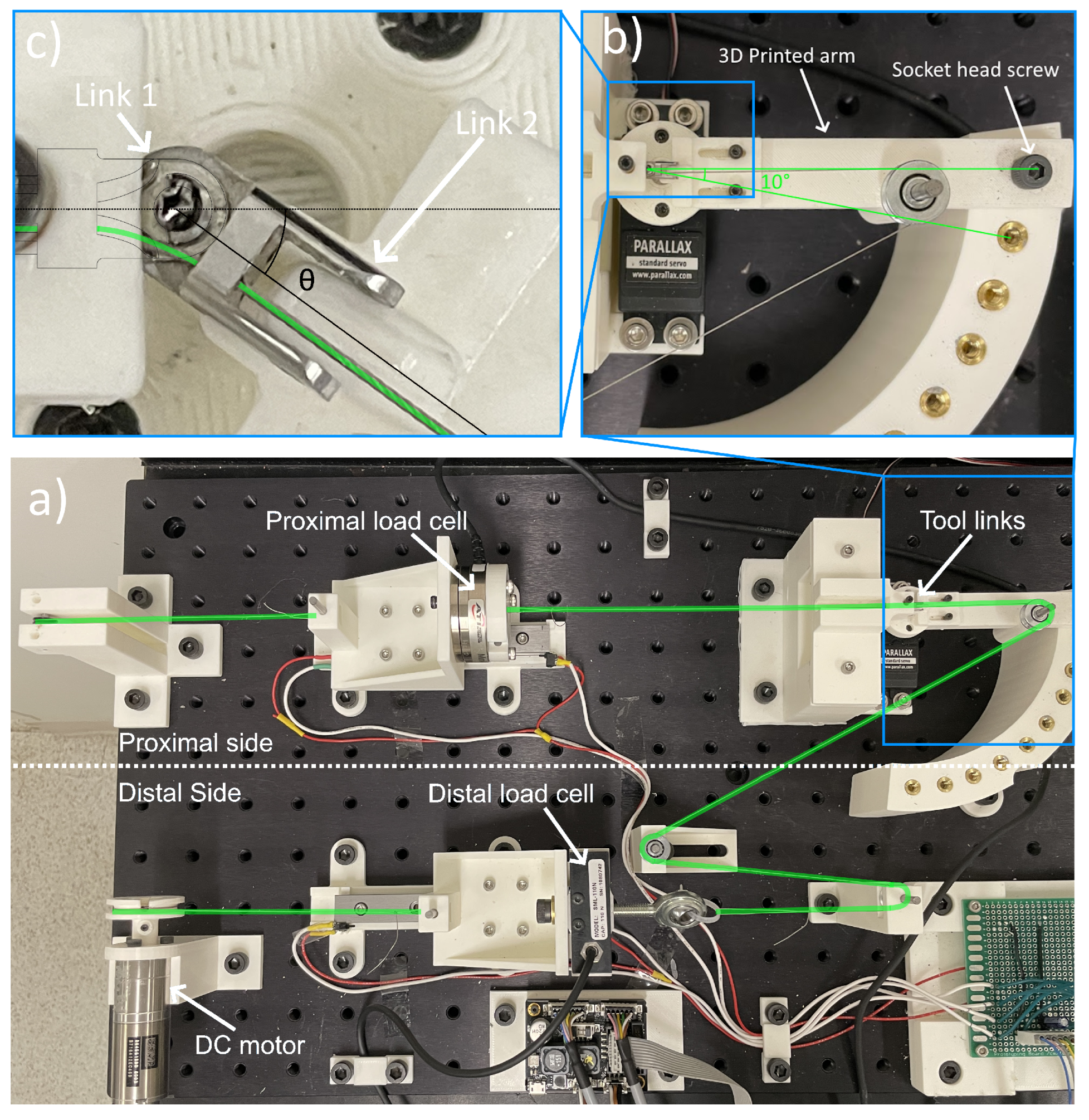
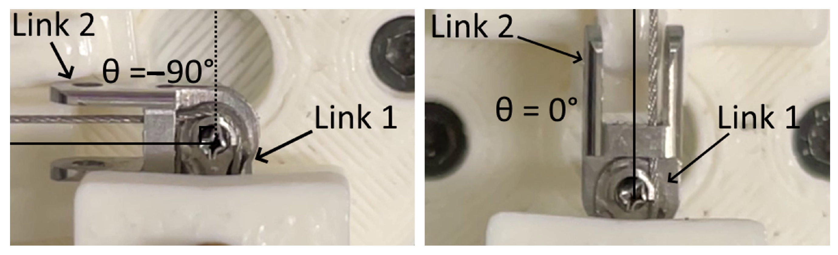
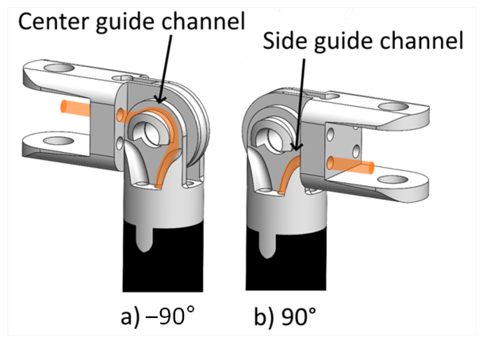
2.1. Experiment Setup
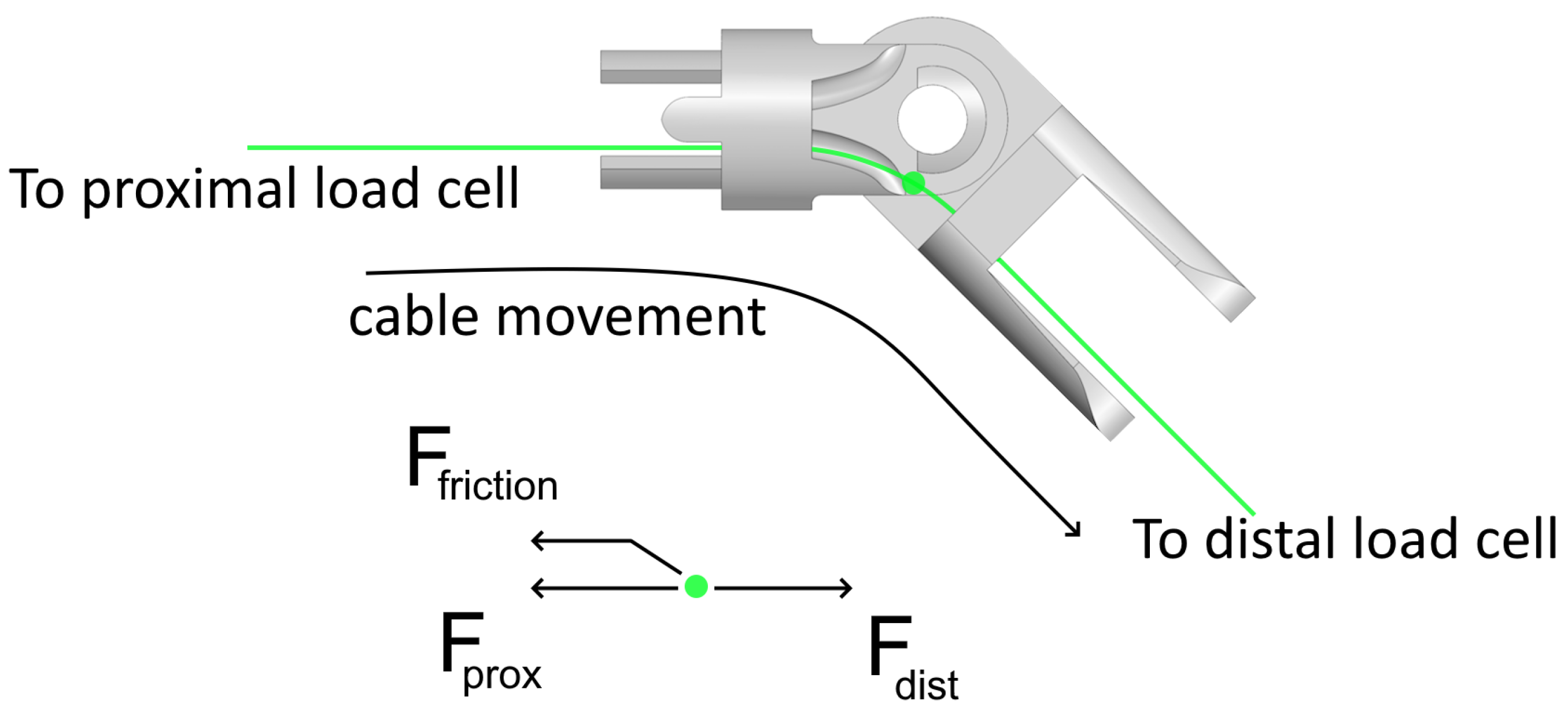
2.2. Data Collection and Processing
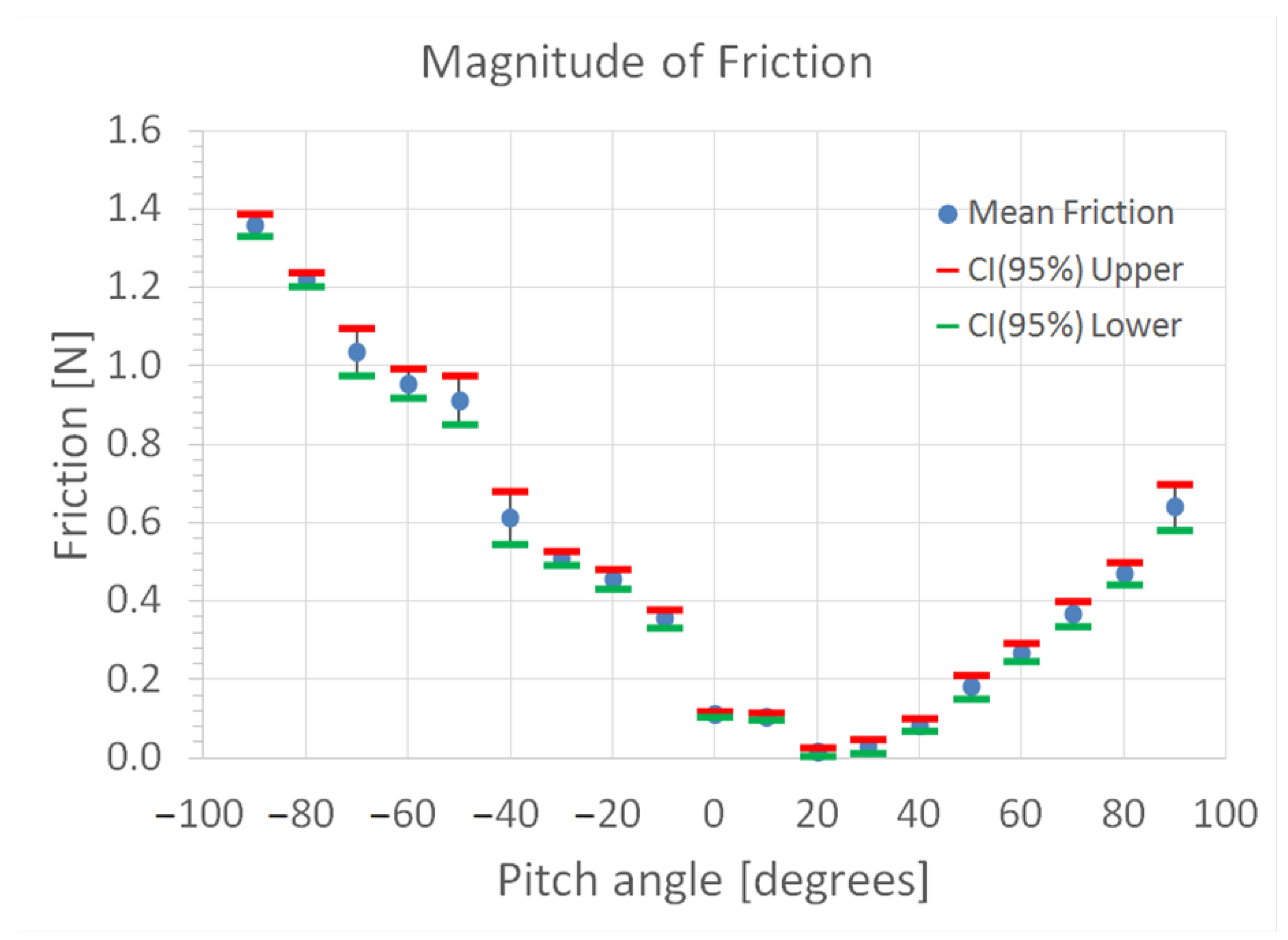
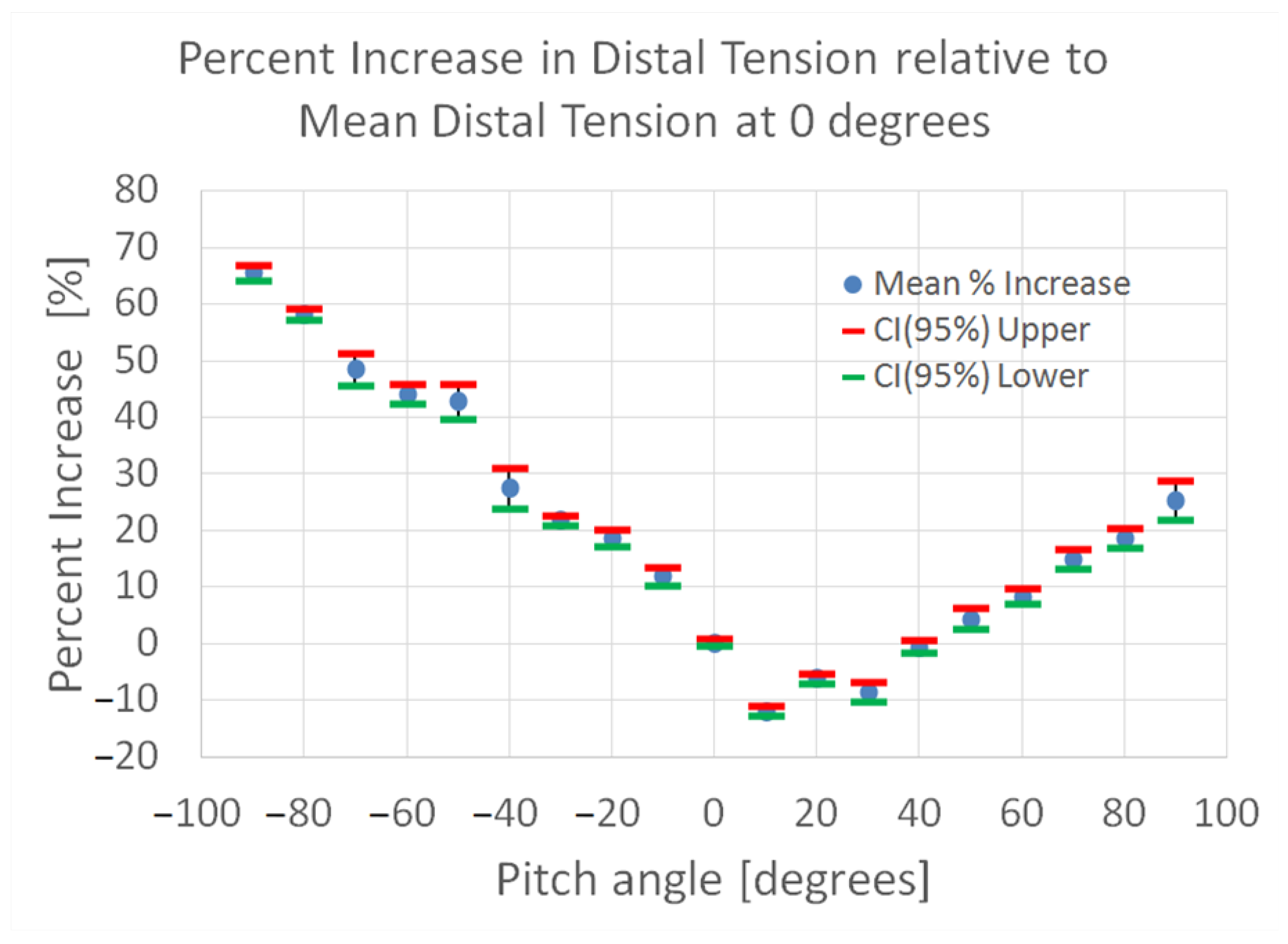
3. Results
4. Discussion
4.1. Significance of Friction
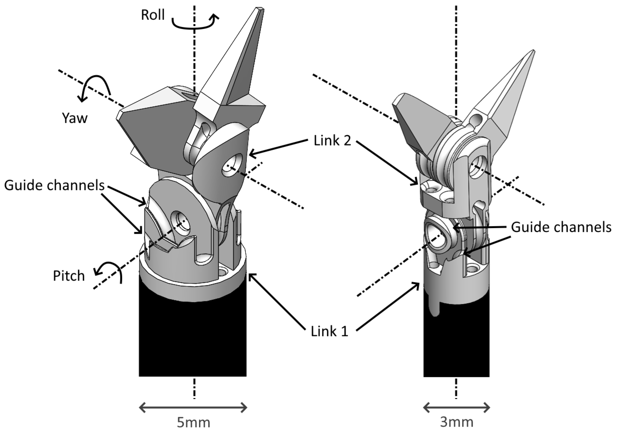
4.2. Comparing the 3 mm Tool with the 5 mm Tool
4.3. Limitations of Study
4.4. Significance of Cable Wear
5. Conclusions
Author Contributions
Funding
Data Availability Statement
Conflicts of Interest
References
- George, E.I.; Brand, C.T.C.; LaPorta, R.A.; Satava, J.M.C.R.R.M. Origins of Robotic Surgery: From Skepticism to Standard of Care. J. Soc. Laparosc. I Robot. Surg. 2018, 22, e2018.00039. [Google Scholar] [CrossRef] [PubMed]
- Podolsky, D.J.; Fisher, D.M.; Wong Riff, K.; Looi, T.; Drake, J.; Forrest, C.R. Infant Robotic Cleft Palate Surgery: A Feasibility Assessment Using a Realistic Cleft Palate Simulator. Plast. Reconstr. Surg. J. Am. Soc. Plast. Surg. 2017, 139, 455–465. [Google Scholar] [CrossRef] [PubMed]
- Nadjmi, D.N. Transoral Robotic Cleft Palate Surgery. Cleft Palate Craniofacial J. 2016, 53, 326–331. [Google Scholar] [CrossRef] [PubMed]
- Khan, K.; Dobbs, T.; Swan, M.C.; Weinstein, G.S.; Goodacre, T.E. Trans-oral robotic cleft surgery (TORCS) for palate and posterior pharyngeal wall reconstruction: A feasibility study. JPRAS Int. J. Surg. Reconstr. 2016, 69, 97–100. [Google Scholar] [CrossRef] [PubMed]
- Podolsky, D.J. Development and Evaluation of a High Fidelity Cleft Palate Simulator for Surgical Training and for Development of a Robotic Approach to Infant Cleft Palate Surgery. Ph.D. Thesis, Institute of Biomaterials and Biomedical Engineering University of Toronto, Toronto, ON, Canada, 2017. [Google Scholar]
- Wu, G.C.Y.; Podolsky, D.J.; Looi, T.; Kahrs, L.A.; Drake, J.M.; Forrest, C.R. A 3 mm Wristed Instrument for the da Vinci Robot: Setup, Characterization, and Phantom Tests for Cleft Palate Repair. IEEE Trans. Med. Robot. Bionics 2020, 2, 130–139. [Google Scholar] [CrossRef]
- Miyasaka, M.; Matheson, J.; Lewis, A.; Hannaford, B. Measurement of the Cable-Pulley Coulomb and Viscous Friction for a Cable-Driven Surgical Robotic System. In Proceedings of the IEEE/RSJ International Conference on Intelligent Robots and Systems (IROS), Hamburg, Germany, 28 September–2 October 2015. [Google Scholar]
- Xue, R.; Ren, B.; Yan, Z.; Du, Z. A cable-pulley system modeling based position compensation control for a laparoscope surgical robot. Mech. Mach. Theory 2017, 118, 283–299. [Google Scholar] [CrossRef]
- Zhou, Z.; Yang, J.; Runciman, M.; Avery, J.; Sun, Z.; Mylonas, G. A Tension Sensor Array for Cable-Driven Surgical Robots. Sensors 2024, 24, 3156. [Google Scholar] [CrossRef] [PubMed]
- Do, T.N.; Tjahjowidodo, T.; Lau, M.W.S.; Phee, S.J. Dynamic Friction-Based Force Feedback for Tendon-Sheath Mechanism in NOTES System. Int. J. Comput. Electr. Eng. 2014, 6, 252–258. [Google Scholar] [CrossRef]
- Do, T.; Tjahjowidodo, T.; Lau, M.; Phee, S. A new approach of friction model for tendon-sheath actuated surgical systems: Nonlinear modelling and parameter identification. Mech. Mach. Theory 2015, 85, 14–24. [Google Scholar] [CrossRef]
- Do, T.N.; Tjahjowidodo, T.; Lau, M.W.S.; Phee, S.J. Performance Control of Tendon-Driven Endoscopic Surgical Robots with Friction and Hysteresis. arXiv 2017, arXiv:1702.02063. [Google Scholar]
- Miyasaka, M.; Haghighipanah, M.; Li, Y.; Matheson, J.; Lewis, A.; Hannaford, B. Modeling Cable-Driven Robot With Hysteresis and Cable–Pulley Network Friction. IEEE/ASME Trans. Mechatron. 2020, 25, 1095–1104. [Google Scholar] [CrossRef]
- Palli, G.; Melchiorri, C. Model and Control of Tendon-Sheath Transmission Systems. In Proceedings of the 2006 IEEE International Conference on Robotics and Automation, Orlando, FL, USA, 15–19 May 2006. [Google Scholar]
- Roy, R.; Wang, L.; Simaan, N. Modeling and Estimation of Friction, Extension, and Coupling Effects in Multisegment Continuum Robots. IEEE/ASME Trans. Mechantronics 2017, 22, 909–920. [Google Scholar] [CrossRef]
- Tan, K.; Shi, H.; Mei, X.; Geng, T.; Yang, J. Control of force transmission for cable-driven actuation system based on modified friction model with compensation parameters. Control. Eng. Pract. 2024, 151, 106035. [Google Scholar] [CrossRef]
- Dai, Y.; Wang, S.; Wang, X.; Yuan, H. A Novel Friction Measuring Method and Its Application to Improve the Static Modeling Accuracy of Cable-Driven Continuum Manipulators. IEEE Robot. Autom. Lett. 2024, 9, 3259–3266. [Google Scholar] [CrossRef]
- Agrawal, V.; Peine, W.J.; Yao, B. Modeling of Transmission Characteristics Across a Cable-Conduit System. IEEE Trans. Robot. 2010, 26, 914–924. [Google Scholar] [CrossRef]
- Kaneko, M.; Yamashita, T.; Tanie, K. Basic considerations on transmission characteristics for tendon drive robots. In Proceedings of the Fifth International Conference on Advanced Robotics ’Robots in Unstructured Environments, Pisa, Italy, 19–22 June 1991; Volume 1, pp. 827–832. [Google Scholar] [CrossRef]
- Chiang, L.S.; Jay, P.S.; Valdastri, P.; Menciassi, A.; Dario, P. Tendon Sheath Analysis for Estimation of Distal End Force and Elongation. In Proceedings of the 2009 IEEE/ASME International Conference on Advanced Intelligent Mechatronics, Singapore, 14–17 July 2009. [Google Scholar]
- Jung, J.H.; Pan, N.; Kang, T.J. Tension transmission via an elastic rod gripped by two circular-edged plates. Int. J. Mech. Sci. 2007, 49, 1095–1103. [Google Scholar] [CrossRef]
- Sorouri, K.; Podolsky, D.J.; Wang, A.M.; Fisher, D.M.; Wong, K.W.; Looi, T.; Drake, J.M.; Forrest, C.R. Utilization of a robotic mount to determine the force required to cut palatal tissue. J. Mech. Behav. Biomed. Mater. 2018, 86, 433–439. [Google Scholar] [CrossRef] [PubMed]
- Carl Stahl Save Industries Product Page: Stainless Steel Cable, Bare 7 × 7, Commerical. 2023. Available online: https://www.savacable.com/stainless-steel-cable-bare-7x7-commercial-1312 (accessed on 2 July 2024).
- Da Vinci X/Xi System Instrument and Accessory Catalog. 2023. Available online: https://www.intuitive.com/en-us/-/media/ISI/Intuitive/Pdf/xi-x-ina-catalog-no-pricing-us-1052082.pdf (accessed on 2 July 2024).


| Parameter | Value |
|---|---|
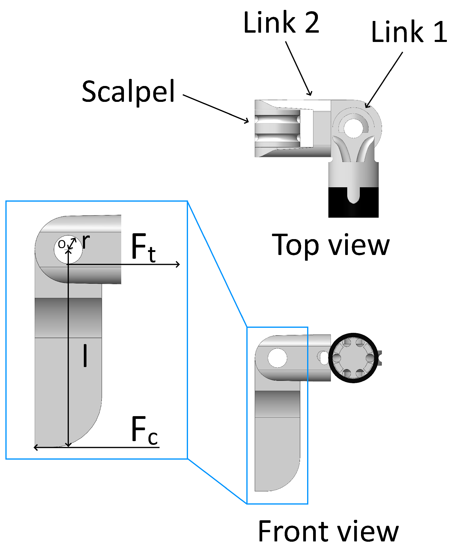
| r | 1.35 mm |
| l | 7.95 mm |
| 10.27 N | |
| 30.24 N |
| Parameter | 3 mm | 5 mm |
|---|---|---|
| Payload (g) | 150 | 200 |
| Cable diameter (mm) | 0.23 | 0.27 |
| Max cable-tension increase (%) | 66.1 | 97.7 |
| Links tested | 1.2 | 1 |
Disclaimer/Publisher’s Note: The statements, opinions and data contained in all publications are solely those of the individual author(s) and contributor(s) and not of MDPI and/or the editor(s). MDPI and/or the editor(s) disclaim responsibility for any injury to people or property resulting from any ideas, methods, instructions or products referred to in the content. |
© 2024 by the authors. Licensee MDPI, Basel, Switzerland. This article is an open access article distributed under the terms and conditions of the Creative Commons Attribution (CC BY) license (https://creativecommons.org/licenses/by/4.0/).
Share and Cite
Ho, C.; Looi, T.; Maguire, G.; Podolsky, D.J. Characterization of Friction within a Novel 3 mm Wristed Robotic Instrument. Actuators 2024, 13, 326. https://doi.org/10.3390/act13090326
Ho C, Looi T, Maguire G, Podolsky DJ. Characterization of Friction within a Novel 3 mm Wristed Robotic Instrument. Actuators. 2024; 13(9):326. https://doi.org/10.3390/act13090326
Chicago/Turabian StyleHo, Caitlin, Thomas Looi, Glenn Maguire, and Dale J. Podolsky. 2024. "Characterization of Friction within a Novel 3 mm Wristed Robotic Instrument" Actuators 13, no. 9: 326. https://doi.org/10.3390/act13090326