Article

Design and Characterisation of a 3D-Printed Pneumatic Rotary Actuator Exploiting Enhanced Elastic Properties of Auxetic Metamaterials

by
Francesca Federica Donadio
1,†,
Donatella Dragone
1,†,
Anna Procopio
1,
Francesco Amato
2,
Carlo Cosentino
1,* and
Alessio Merola
1
1
Biomechatronics Laboratory, Department of Experimental and Clinical Medicine, Università degli Studi Magna Græcia di Catanzaro, Campus Universitario “S. Venuta”, 88100 Catanzaro, Italy
2
Dipartimento di Ingegneria Elettrica e delle Tecnologie dell’Informazione, Università degli Studi di Napoli Federico II, Via Claudio 21, 80125 Napoli, Italy
*
Author to whom correspondence should be addressed.
These authors contributed equally to this work.
Actuators 2024, 13(9), 329; https://doi.org/10.3390/act13090329
Submission received: 30 July 2024 / Revised: 27 August 2024 / Accepted: 28 August 2024 / Published: 30 August 2024
(This article belongs to the Special Issue Advanced Technologies in Soft Pneumatic Actuators)

Abstract

:
This paper describes the design and characterisation of a novel hybrid pneumatic rotational actuator that aims to overcome the limitations of both rigid and soft actuators while combining their advantages; indeed, the designed actuator consists of a soft air chamber having an auxetic structure constrained between two rigid frames connected by a soft hinge joint inspired by the musculoskeletal structure of a lobster leg. The main goal is to integrate the advantages of soft actuation, such as inherent compliance and safe human–robot interaction, with those of rigid components, i.e., the robustness and structural stability limiting the ineffective expansion of the soft counterpart of the actuator. The air chamber and its auxetic structure are capable of leveraging the hyper-elastic properties of the soft fabrication material, thereby optimising the response and extending the operational range of the rotational actuator. Each component of the hybrid actuator is fabricated using a 3D-printing method based on Fused Deposition Modeling technology; the soft components are made of thermoplastic polyurethane, and the rigid components are made of polylactic acid. The design phases were followed by some experimental tests to characterise the hybrid actuation by reproducing the typical operating conditions of the actuator itself. In particular, the actuator response in unconstrained expansion and isometric and isobaric conditions has been evaluated. The experimental results show linearity, good repeatability, and sensitivity of the actuator response vs. pneumatic pressure input, other than a small percentage hysteresis, which is ten times less than that observed in commercial soft pneumatic actuators.

1. Introduction

A multiple of tasks of locomotion and manipulation can be accomplished by controlling the interaction dynamics between the robot body and the surrounding environment; the robot actuation can be achieved through conventional and, therefore, rigid actuators or through the adoption of innovative actuators which are characterised by intrinsically compliant structures.
Rigid actuators are commonly used in applications requiring accurate and repeatable movements, and, therefore, they represent the preferred standard for the actuation of Industrial Robots and other applications. However, these actuators have many limitations, including their large size and weight, low safety in human–robot interaction, and mechanical complexity [1].
Therefore, innovative solutions of soft actuation are proposed to overcome the limitations of rigid actuators. The mechanical compliance observed in soft actuators results from the flexible (and often hyper-elastic) fabrication materials. These materials allow the generation of different motion acts, including bending, contraction, expansion, and torsion, to efficiently adapt the robot performance to the external stimuli while fulfilling some safety constraints in physical human–robot interaction [2]. It is evident that soft robots represent a class of robots that offer enhanced flexibility and freedom of movement compared to their rigid counterparts. This renders them an optimal choice for a multitude of applications, including the manipulation of small and fragile objects, the execution of delicate tasks in wearable robotics, minimally invasive surgery and rehabilitation, and safe human–robot interaction [3]. Furthermore, some hyperelastic and biologically compatible materials can be used to fabricate robotic hardware complying with the requirement of tissue integrity in robotic surgery.
Conventional techniques of fabrication of Soft Robots typically entail creating moulds and filling them with silicone or resin in a semi-liquid state [4]. This results in some laborious, multi-step, and operator-dependent processes, which cause manufacturing variability and limit repeatability. The techniques used are soft lithography, retractable pin casting, lost-wax casting, and roto-molding. These fabrication procedures require post-processing and do not allow for complex internal actuator geometries. Therefore, additive manufacturing (AM) techniques, especially 3D printing like the one used in this work, can overcome the described limitations, offering several advantages in terms of cost, speed, complexity, accuracy, and repeatability [5,6,7]. Moreover, AM facilitates the expeditious customisation of the actuator geometry by enabling the configuration of print parameters within the 3D-printing software. The most recent and relevant developments in AM applications pertain to fabricating actuators and structures for soft robotics.
A common category of soft actuators is the pneumatically actuated type. The main advantages of adopting such actuators are the high safety, favourable power-to-weight ratio, rapid response time, and low cost. These actuators are suitable for use in all the applications subject to electromagnetic interference problems since an efficient actuation can be guaranteed without using ferromagnetic or electronic components [3,8,9]. The pneumatic and soft actuators class also includes the Pneumatic Artificial Muscles (PAMs), which can be realised through various structural and geometric configurations. Soft actuators are generally suitable for low-force operations, such as those performed in neurosurgery or retinal surgery, due to their low stiffness [10]. Some factors, including geometric parameters, differences in manufacturing sequence, production time, and environmental conditions, significantly influence the performance of this type of actuator. In addition, the geometric dimensions and the mechanical response of the hyperelastic material can affect the repeatability of the manufacturing process other than the control performance of the final product of the robotic hardware. To overcome the limitations inherent in soft actuators, there are several solutions, such as limiting the radial expansion of the actuator by employing fibres, using geometries that reproduce origami patterns, or developing hybrid structures [11], like the one designed and characterised in this work.
Hybrid pneumatic actuators consist of rigid frames and soft chambers driven by air pressure. This design ensures that the air chambers of the actuator do not deform ineffectively [12]. The hybrid solution, thanks to the assembly of soft and rigid components, can support accurate motion/interaction control of bending movements, facilitating both the torque transmission and the implementation of controllable-compliance mechanisms [13].
The interposition of rigid frames and soft chambers within the structure of hybrid pneumatic actuators offers significant advantages over purely soft systems since, e.g., some rigid frames can constrain the expansion of the soft chambers, allowing both controllable compliance and more accurate motion control.
This paper presents a hybrid rotary actuator that integrates both rigid and soft structures with the objective of combining the advantages of rigid and soft robotics, thus overcoming their respective limitations. The primary objective was to develop a 3D-printable pneumatic actuator with reduced weight, enhanced output torque, and minimal nonlinearity in the mechanical response of the actuator itself, thereby improving performance, particularly in terms of controllability during motion and interaction tasks in comparison to conventional actuators (see, e.g., [14,15]).
In the literature, the design and 3D printing of soft pneumatic actuators generating rotational motion is not well investigated since the prevailing solutions of pneumatic actuation are based on a sequence of soft air chambers (see, e.g., [16,17,18]), which are also adopted in the Pneu-nets configuration (see, e.g., [19,20]); such solutions are unsuitable for generating rotational motion since the bending of a soft actuator/robot can be generally modulated only along its continuum kinematics. Instead, pneumatic rotary soft actuators can guarantee a fixed centre of rotation between two consecutive sections of the actuator body in response to an air pressure input within the elastic chambers of the actuator (see, e.g., [17,21]).
The term ‘auxetic’ is derived from the Greek and means ‘which tends to increase’. Auxetic structures are metamaterials with a negative Poisson’s coefficient, which is generally used to measure the ratio of the transversal strain in response to a longitudinal deformation. Materials with a negative Poisson’s coefficient exhibit lateral expansion instead of shrinking in the direction perpendicular to the stretch [22]. Auxetic structures generally comprise repeated single-unit cells in periodic patterns. These structures can be advantageously adopted in soft robots because they enable complex movements without requiring multiple actuators. The auxetic configurations allow the modulation of simple inputs, such as a pressure pulse, for generating a sequence of complex outputs, including bending, tension, and torsion. Auxetic structures exhibit additional and advantageous features, including enhanced shear resistance, vibration absorption, increase in the Degrees of Freedom (DoFs) [23], and structural stability [24].
The majority of the current research on auxetic structures is based on planar lattices. Nevertheless, 3D printing has led to an increasing prevalence of three-dimensional auxetic structures created by extruding adjacent two-dimensional auxetic cells to generate patterns or by rotating the individual cell 90 ° along the X-axis and Y-axis, respectively, (see, e.g., [25,26]). The advantage of 3D printing is that it allows for precise control over geometry and enables the creation of more complex auxetic patterns using a variety of materials, such as PLA, acrylonitrile butadiene styrene (ABS), or TPU (see, e.g., [27,28,29,30]).
In this work, the structure of the hybrid pneumatic actuator, which is designed for generating rotational motion, combines an internal soft chamber with an external frame to generate efficient and robust rotation while constraining undesired deformation of the compliant chamber [16]. Moreover, the air chamber of the actuator has an auxetic configuration to enhance and extend its expansion towards the elastic limits of the material.
Optimising the motifs of the auxetic lattices makes it possible to improve the performance of soft actuators and robots in terms of sensitivity and linearity of their mechanical response. Indeed, for the first time in the field of soft robotics, the mechanical properties of auxetic lattices—towards the realisation of soft robots based on auxetic structures—were exploited in [31]; the tensile tests therein have shown the possibility to shape the stress vs. strain response of cylindrical auxetic structures, e.g., by amplifying the linearity range of the response.
However, the above-mentioned references on auxetic lattices do not consider any pneumatic actuation or inflatable and tridimensional structures. Therefore, the main goal of the present work is to extend the advantages of auxetic lattices, mainly in terms of compliance and controllability of the mechanical response, to a more wide and useful context of applications in the Soft Robotic field, by developing some novel actuation solutions—based on tridimensional auxetic structure—in a pneumatic rotational domain.
In addition to the enhanced mechanical response and controllability of the rotation, the auxetic structure of the actuator presented in this work offers further advantages, including optimised material support and a reduced time requirement for printing the actuator.
The main contribution can be summarised as follows: (i) design and 3D printing of a novel pneumatic rotary actuator characterised by an auxetic compliant structure to obtain some optimised characteristics rotation/torque vs. pressure input, (ii) experimental characterisation of the mechanical response and validation of the actuator performance through a series of tests to identify the relevant properties and key parameters of the actuator response resulting from the novel rotary auxetic structure.
This paper follows the following organisation. Section 2 presents the actuation principle based on the mechanical behaviour of auxetic lattices, providing an overview of the key parameters of the peculiar response of auxetic structures; the main steps of design, CAD-3D modelling, and additive manufacturing are presented in the same Section. The experimental tests for identifying the characteristics of the auxetic actuator and the discussion of the results are reported in Section 3. Some concluding remarks are given in Section 4.

2. Materials and Methods

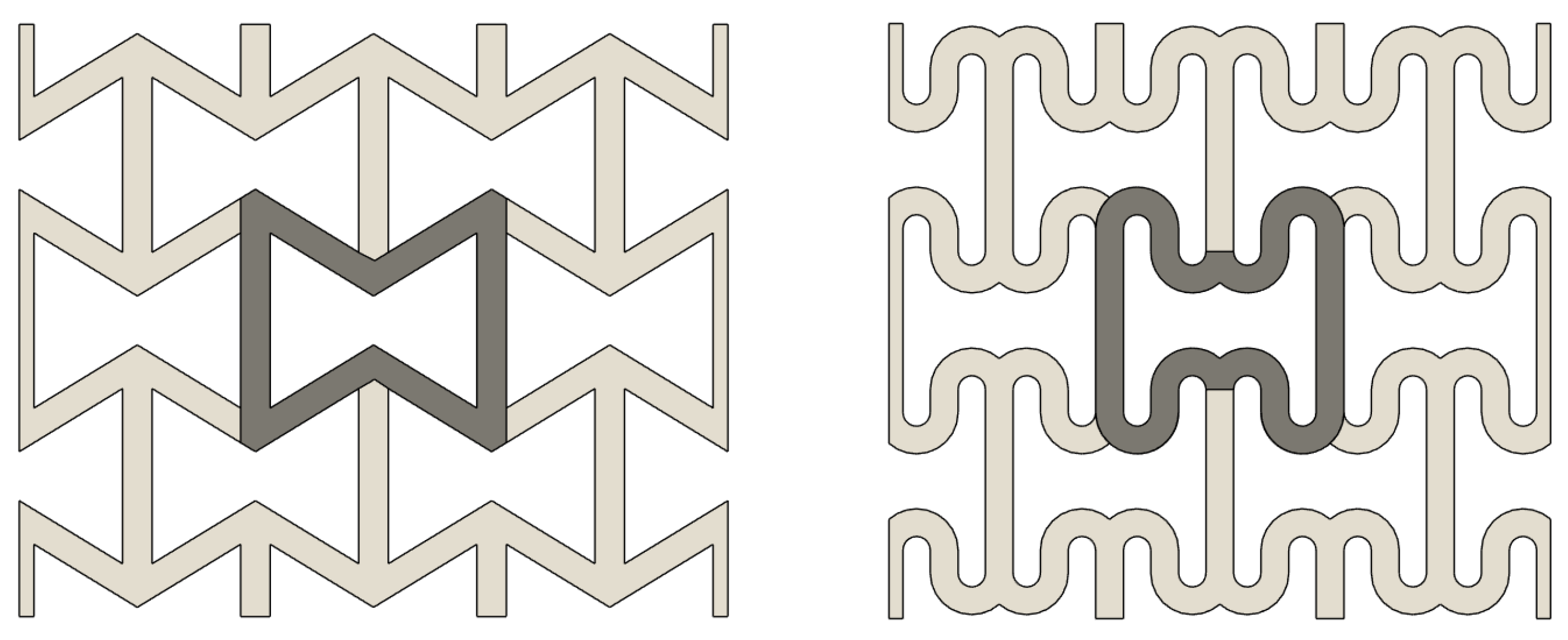
2.1. Actuation Principle Based on Auxetic Metamaterials

Poisson’s ratio ν is a dimensionless index of Poisson’s effect, according to whom the deformation along an axis of a specimen (expansion or compression) implies a deformation along the direction perpendicular to the one of the application of the loading (compression or expansion, respectively). This index can be calculated as the negative ratio of transverse strain ( ϵ t r a n s v e r s e / l a t e r a l ) to axial strain ( ϵ l o n g i t u d i n a l / a x i a l ).
ν = ϵ t r a n s v e r s e / l a t e r a l ϵ l o n g i t u d i n a l / a x i a l
The ratio’s negative value is due to the fact that when a load is applied to expand the sample in a given direction, contraction occurs in the perpendicular direction (and vice versa). The expansion is positive, while the contraction is negative; thus, the minus sign was introduced to provide a positive coefficient for conventional materials. In 1987, Lakes [32] fabricated a repetitive foam structure with a Negative Poisson’s Ratio (NPR), giving rise to Auxetic metamaterials. Auxetic lattices can expand laterally when undergoing axial stretching, or analogously, they can oppose densification when undergoing axial compression. After the idea by Lakes was developed and spread, a lot of different geometric configurations were conceived—all characterised by the repetition of a single cell—such as re-entrant [32,33,34], star-shaped [35,36], chiral [37,38], double-arrow [39,40], and sinusoidal [41,42]. Among these structures, the re-entrant honeycomb (REH) motif is the most widespread; it is based on a cell unit derived from a classical hexagonal honeycomb (HH) structure, but it reveals a better behaviour in dissipation of energy with respect to classical honeycombs under the same strain [43]. REH can be obtained by replacing the bilateral concave cell walls of HH with convex ones [44]. REH auxetic path with rounded corners was introduced in [45], showing a better behaviour with respect to REH (see Figure 1).
The advantage of using this counter-intuitive behaving class of metamaterials is that the auxetic behaviour enhances the mechanical properties: as said before, when undergoing axial compression, the auxetic structure contracts laterally, resulting in higher specific energy absorption and dissipation [46,47], thus resisting fragmentation [35], increasing indentation resistance [48] and variable permeability [48]. At the same time, assuming an expansion of each single cell of the auxetic lattices in Figure 1, e.g., due to an internal pressure input, the positive Poisson’s ratio ensures that the overall area of an initially densified lattice (or volume in the case of closed structures) can increase. Therefore, the peculiar variation in volume in auxetic metamaterials, which is not found in conventional structures, allows for the enhanced controllability of mechanical compliance and better sensitivity to a pressure input in the case of implementation of the auxetic structure with soft pneumatic actuation.
All the above-mentioned lattices are planar; starting from a planar motif, a three-dimensional auxetic inflatable structure is presented in this work. To the best of the authors’ knowledge, this structure has never been developed before.
To understand the behaviour of auxetic lattices and the derived actuator structure, the key parameters in the deformation mechanics are analysed in the following development, with reference to the planar analysis on the chosen motif, i.e., a REH structure with rounded corners.
For small strains, the (negative) Poisson’s ratio ν for REH motifs can be calculated from (1), taking ϵ x as transverse strain and ϵ y as axial strain [29,44].
For both transverse and axial directions, the strain can be derived from the sample’s initial and final lengths, respectively, L 0 and L f , normalised to its initial length. Initial and final lengths in the x direction are denoted by L 0 x and L f x , respectively. Thus, ϵ x can be calculated as
ϵ x = L f x L 0 x L 0 x
Analogously, initial and final lengths in the y direction are given by L 0 y and L f y , respectively. Thus, ϵ y can be calculated as
ϵ y = L f y L 0 y L 0 y
The ranges of values of the Poisson’s ratio for auxetic metamaterials ([29,49]) can be summarised as follows:
  • [ 1 , 1 ] for 2D structures;
  • [ 1 , + 1 / 2 ] for 3D structures with isotropic behaviour;
  • ( , 1 ] for 3D structures with anisotropic behaviour.
Another important parameter, which influences the elastic behaviour of auxetic structures [50], is the relative density ρ r . This latter can be expressed as the ratio of the effective area of the auxetic structure—which is the area within internal and external perimeters of the auxetic motifs—to the area of the cell material—which is the area bounded by the external perimeters of the cell—[44,50,51] and it can be calculated as a ratio of the area within internal and external walls of the auxetic motifs and the area bounded by the external walls of the cell.
ρ r = 4 a c · c o s θ + 4 a b · c o s θ + 8 π a · c o s θ R i + 8 π a 2 · c o s 2 θ a 2 · s i n θ c o s θ 10 a c · c o s θ + 8 c R i 4 b R i + 4 π a R i · c o s θ + 4 π a 2 · c o s 2 θ
The formula refers only to a quarter of the cell due to its symmetry (Figure 2). Following the notation adopted in the representation of Figure 2, considering the curves closer to the symmetrical axis, a is the distance between the point of the inner arc closer to the symmetric axis (in green) and the intersection point between the symmetric axis and the external arc (in violet), whereas its inclination with respect to the symmetric axis itself is denoted with θ ; b is the vertical distance between two adjacent arcs of which one is inner and one is external, c is half of the vertical distance between two external arcs, and R i is the internal radius of each arc. The thickness of the auxetic structure wall is denoted by 2 a c o s θ and is assumed to be constant to obtain (4).

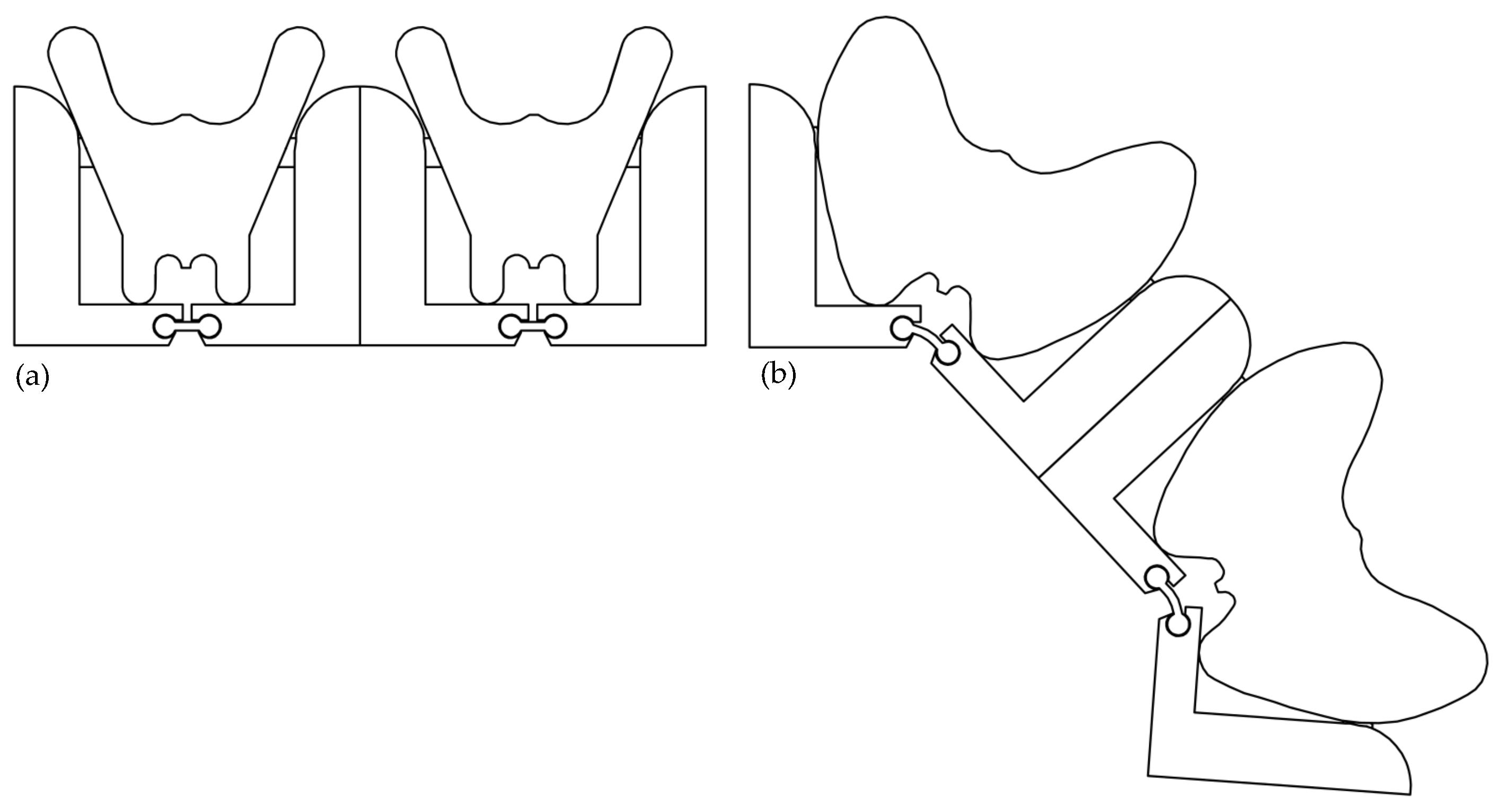
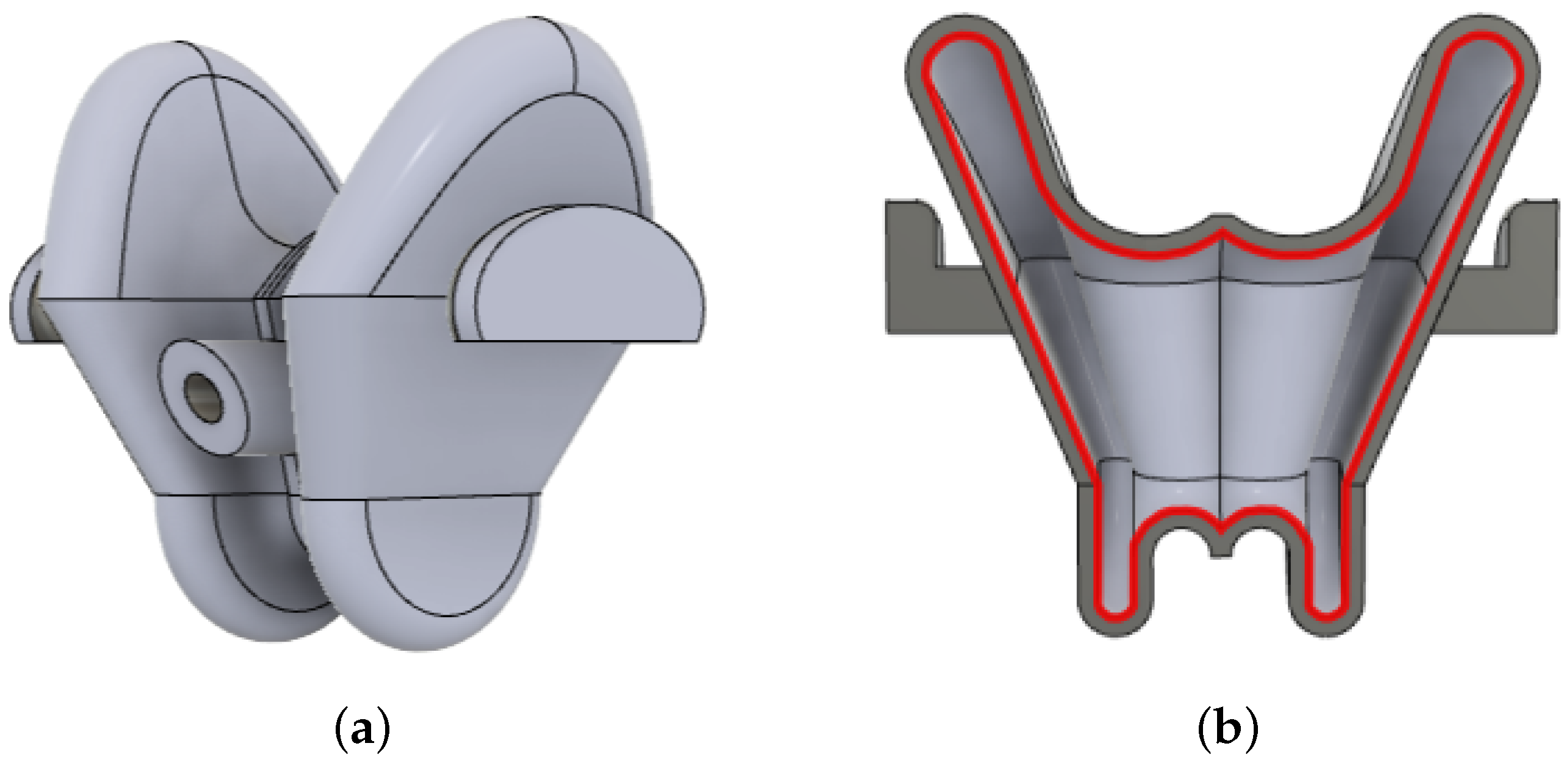
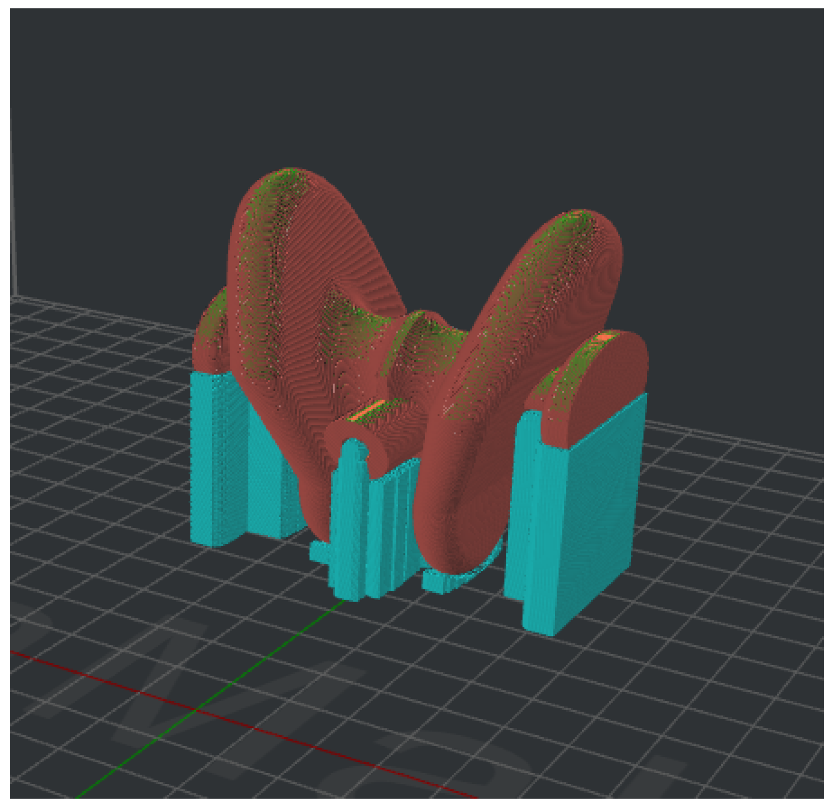
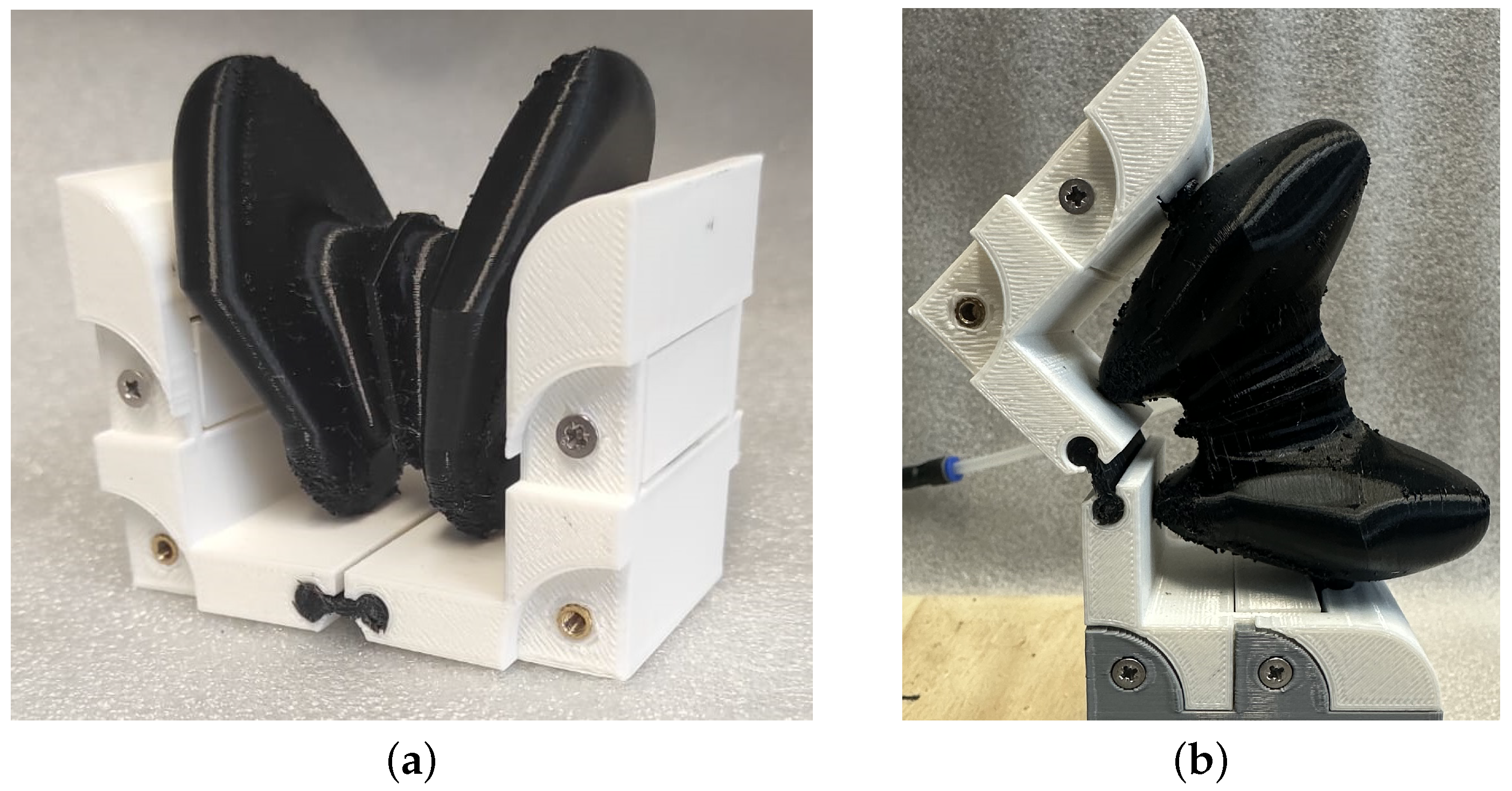
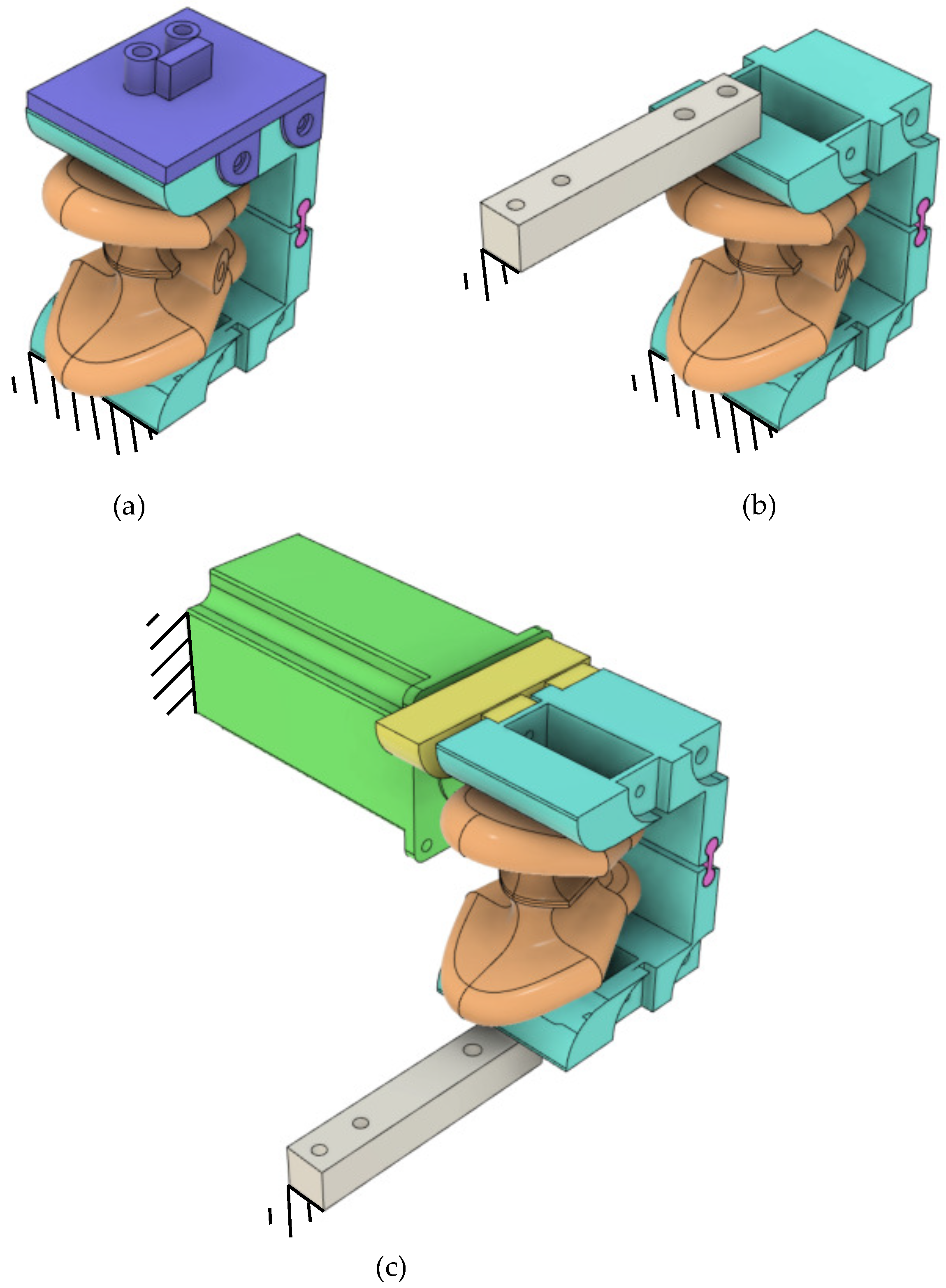
2.2. Three-Dimensional Design and Additive Manufacturing

Soft Robots have received considerable attention due to the main advantages previously discussed, but their manufacture is challenging.
The hybrid pneumatic actuator described in this paper is manufactured using a 3D-printing method based on FDM technology. This technique, which involves the deposition of a filament layer-by-layer to create three-dimensional objects, differs from the manufacturing techniques conventionally adopted to fabricate soft pneumatic actuators [52]. The 3D printer used is a Raise3D Pro2 Plus, which has a direct-drive extrusion system suitable for printing soft filaments and a dual extruder that allows 3D printing with two different materials simultaneously or with soluble support material.
The 3D model of the hybrid pneumatic actuator was developed through the 3D-CAD software AutoDesk Fusion 360. As described above, the actuator prototype embodies rigid and soft structures which are printed in PLA and TPU materials. Two identical rigid frames 3D of PLA are placed, specularly, at the ends of the soft actuator and connected to the actuator itself through a key-lock mechanism.
The rigid frames are designed to connect to each other (see Figure 3) and to other parts, i.e., fixed frame, through repetition of attachment points (in correspondence to the arc-shaped cavities in Figure 3), in order to fulfil the requirement of modularity and to guarantee a serial connection of more rotational actuator units.
The semi-frames surrounding the actuator’s soft chamber are joined to each other through a TPU-made flexural hinge to facilitate the relative rotation between the extreme sections of a single actuator unit. In this configuration, the rotation centre can be localised in correspondence with the position of the flexural hinge.
The interconnection of soft actuators and rigid frames with related joints enables the designed actuator to be classified as a hybrid one. This configuration allows the generation of rotary motion while simultaneously preventing the ineffective deformation of the extremities of the soft air chamber.
Although the 3D printer used is capable of simultaneously extruding two different materials in a single print cycle, it was decided not to proceed with monolithic printing of the hybrid actuator because according to Arleo et al. [53], since there could be significant disadvantages such as low affinity between materials, increased print time, and material waste in the event of errors. In addition, using separate prints allows for the precise definition of printing configurations for each component, such as fabrication parameters and printing orientation, which also allows for support reduction. The design and realisation of the soft pneumatic actuator involved several steps due to the iterative refinements in the optimal geometry and the inherent limitations of the ’printability’ of the materials. Different pneumatic actuator configurations were tested to find the best air tightness and deformation in response to the input air pressure. The solution to the latter adopts an air chamber with an optimised auxetic structure.
In particular, a 3D bellows actuator with an auxetic REH-type structure with rounded corners and a divergent profile was designed and realised, starting from the 2D model described in Section 2.1 (see Figure 4).
Air tightness is a common problem for soft pneumatic actuators and can be overcome by manipulating various geometric parameters. In particular, air tightness depends on wall thickness, a trade-off between air tightness, and deformation. According to [54,55], the air tightness of the actuator was achieved using five perimeters corresponding to a wall thickness of 2 mm, i.e., five adjacent lines of 0.4 mm extruded filament. Furthermore, to enhance the system’s airtightness, the air connector was integrated into the actuator wall and flows into the auxetic air chamber (see Figure 4a).
Other printing parameters were set through the IdeaMaker slicing software, developed by Raise3D®, to guarantee the best result regarding air tightness and deformation. Furthermore, the slicing software also allows the choice of the printing orientation to limit the use of supports. In particular, these latter ones were only used in contact with the parts interconnecting with the rigid frames, which were not subject to expansion, in order to guarantee the complete absence of air leaks (see Figure 5). The 3D-printing settings for the soft pneumatic actuator are listed in Table 1.
The commercial TPU utilised to fabricate the soft pneumatic actuator is NinjaFlex, produced by Ninjatek®, with Shore 85A hardness, which offers an optimal balance between flexibility and strength. Furthermore, this material can stretch up to 660%, making it ideal for producing parts that need to be bent or compressed periodically, as in our case.
The soft pneumatic actuator was designed to miniaturise its dimensions. Considering the factors mentioned above, the final dimensions of the device are 67.5 mm × 63.6 mm × 50.0 mm, with a weight of 28 g.
The commercial filament used to fabricate the rigid frames of the hybrid actuator (shown in Figure 6) is Premium PLA produced by Raise3D. The 3D-printing settings for the rigid frames are listed in Table 2. The dimensions of the rigid frames are proportional to those of the soft pneumatic actuator: 59.4 mm × 48.0 mm × 38.7 mm, respectively, and each frame weighs 22 g.

3. Experimental Tests and Results

3.1. Experimental Setup

A dedicated experimental setup was designed and built for characterising the mechanical behaviour (and its key parameters for evaluating, e.g., repeatability and linearity) of the hybrid pneumatic actuator, mainly from the actuator output in terms both of angular displacement and torque in response to a pressure input. To measure and digitally acquire the angular displacement of the actuator, an interconnection between its upper rigid frame and an inertial measurement unit (IMU, MPU6050) was designed and 3D-printed in PLA (depicted in purple in Figure 7a). In the experimental setup, a stepper motor (NEMA 23, with a peak current of 2.8 A, a maximum torque of 1.9 Nm, and a step 1.8°) having its output shaft collinear to the hinge joint of the actuator, is connected to the actuator via the yellow support shown in Figure 7c, in order to constrain the rotation of the actuator. Two solutions were designed and fabricated to mount a load cell (SEN-13329, SparkFun, measurement range 0–10 kg) in contact with both the upper and lower frames (see Figure 7b and Figure 7c, respectively) to indirectly measure the resistant torque exerted by the actuator. The desired air-pressure values are achieved within the actuator chamber through a closed-loop pressure regulator (MPPES-3-1/4-6-010) with a built-in pressure sensor; each pressure set-point is generated as an analogue signal input to the regulator through an ATmega328-based Arduino R3 microcontroller and an off-the-shelf board based on digital–analogue converter TLV5618 and operational amplifier LM358. Therefore, the Arduino microcontroller manages both the motor/regulator driving and digital acquisition of the experimental data.

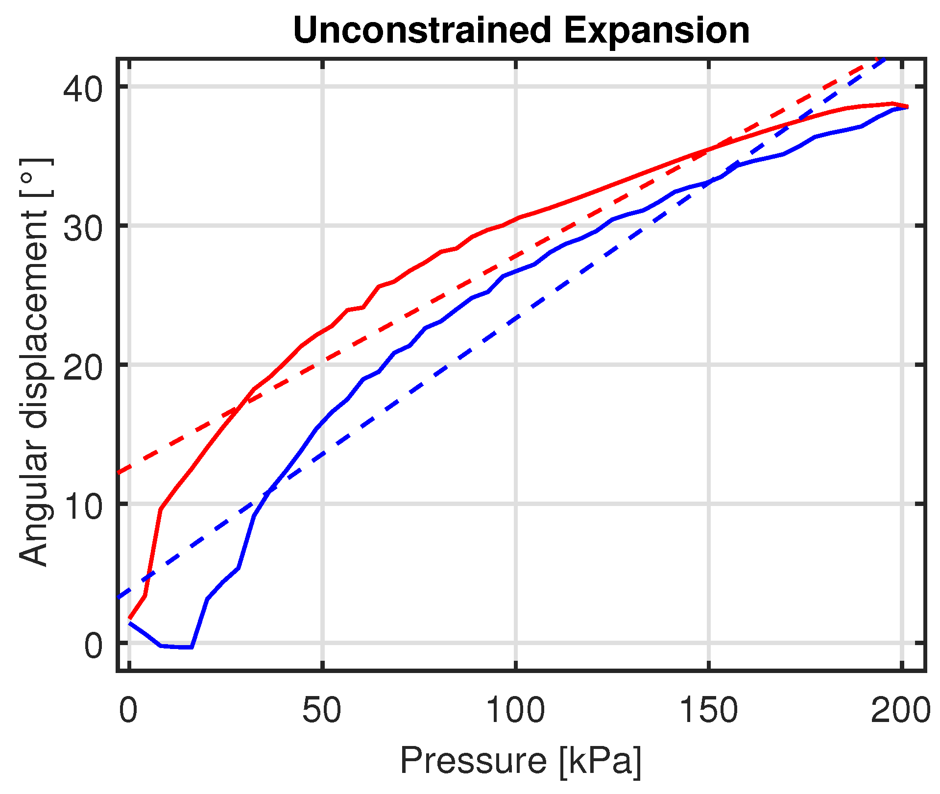
3.2. Identification of the Mechanical Response of the Actuator

Initially, the rotational behaviour of the proposed actuator in response to the inlet pressure was characterised. The experimental setup, shown in Figure 7a, consists of the bottom rigid frame of the hybrid actuator being fixed, while the upper frame is free to move. The IMU is attached to the upper frame to measure the angular displacement resulting from the actuator’s motion when inlet pressure is introduced. The pressure regulator provides the soft pneumatic actuator with increasing pressure, which is modulated through a series of discrete steps, each increasing by 4 kPa every 0.1 s. Both angular displacement and pressure data are digitally recorded using the embedded microcontroller. To ensure the accuracy and consistency of the data, each test was repeated ten times.
Figure 8 represents the actuator response obtained as a mean of ten repetitions of a sequence of inflation–deflation in the range 0–200 kPa; the resulting Root Mean Square Error (RMSE) from the mean curve is 0.67 and a percentage hysteresis of 32.8% was achieved. This latter is calculated by dividing the maximum hysteresis amplitude by the output span of the force response and multiplying it by 100.
To keep the soft actuator within a mid-range of deformation of its air chamber, the input pressure is modulated within the range 0–200 kPa, and correspondingly, an angular range of 40 degs, which can be considered satisfactory for connecting a single module to other ones, was achieved.
A linear regression model of the mechanical response in both expansion and compression phases can be obtained using Matlab’s Curve Fitting Toolbox through a first-order fitting. In Table 3, a goodness-of-fit measure is provided through a R 2 index for each expansion/compression phase.

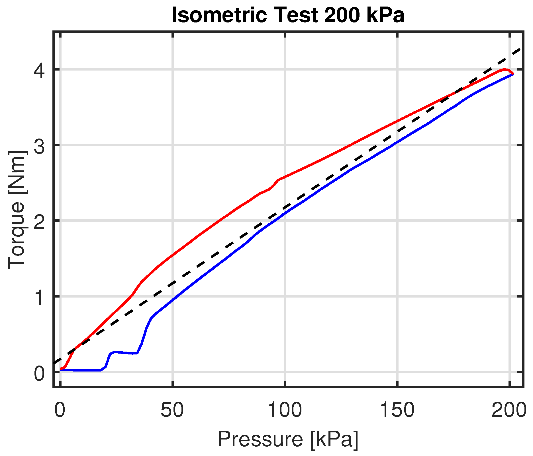
3.3. Isometric Tests

The mechanical response of the auxetic actuator has also been characterised using an isometric setup, as shown in Figure 7b. In this configuration, the lower rigid frame of the actuator is fixed, and the upper frame is constrained by the load cell. The load cell measurements were recorded during the experiments while air was inflated into the actuator. These data were used to calculate the torque vs. actuation pressure characteristics.
The isometric setup reproduces the operating conditions during torque control, in which the air pressure within the actuator chamber is modulated to regulate the torque transmitted between the actuator and the load. Additionally, this characterisation is useful to quantify the payload of the actuator in correspondence with the peak input pressure, thus determining the maximum load the actuator can move at a peak pressure of 200 kPa.
In the isometric setup, the rigid frames are held in a position corresponding to the actuator’s nominal closed configuration while the actuator itself is inflated. The torque measurement can be indirectly obtained from the force signal of the load cell and the effective moment arm over the rotation centre, which is provided by the flexural hinge joint of the actuator. The load cell is in contact with the actuator in correspondence with the extremity of the arm of the lower rigid frame of the actuator.
The pressure input is incrementally varied by 2 kPa per step, reaching a maximum pressure of 200 kPa in 100 steps. The time interval between two consecutive steps is 0.1 s. The mean torque value was obtained from ten repetitions for each sampling pressure, resulting in an RMSE of 0.3094 Nm. The lower branch of the loop corresponds to the expansion phase.
From the response in Figure 9, it is possible to correlate the torque peak, of about 40 Nm, to the actuator payload at the maximum input pressure of 200 kPa. One notable enhancement resulting from the meticulous design of auxetic chambers is the achieved linearity in torque vs. pressure characteristics.
The actuator response can be described by a linear function f ( p ) = m p + q , with m = 0.020 and q = 0.170; the goodness-of-fit is expressed by R 2 = 0.956 for the results in Figure 9. The RMSE index value, with respect to the regression line, was calculated for the low range of pressure between 0 and 45 kPa, where the actuator exhibits a less linear behaviour; this latter corresponds to 5.298 Nm. The experimental loops showed no drift effect attributable to stress relaxation in the hyperelastic material.

3.4. Isobaric Tests

The isobaric setup illustrated in Figure 7c was further employed to characterise the actuator response. In this setup, a constant pressure is kept in the actuator chamber through a proportional pressure regulator FESTO MPPE. The upper rigid frame is constrained to the stepper motor shaft (identified by the yellow connector in the same Figure 7c).
The top arm of the upper frame starts from the approximately horizontal position; the angular displacement from this initial position is obtained through the IMU readings. For a set of constant inflation pressures of the actuator, the stepper motor is controlled to compress and release the inflated actuator; the corresponding torque profiles are acquired by exploiting the same principle of indirect measurement exploited for the isometric setup. The stepper motor is rotated at 18 degs/s in order to obtain suitable conditions for neglecting velocity-dependent nonlinear effects.
A series of five experimental curves was collected at pressure values of 0, 50, 100, 150, and 200 kPa. Maintaining a constant pressure, the actuator undergoes controlled compression via the stepper motor, whose shaft is aligned with the rotation axis provided by the flexural hinge of the actuator. After reaching a maximum displacement of 14 degs, the rotation is reversed to trace a loop. For each pressure value, two first-order polynomials were determined to best fit both the compression and expansion phases, respectively, with a goodness-of-fit index R 2 ranging from 0.975 to 0.989 (see Table 4).
The advantage of the linear behaviour can be mainly attributed to the auxetic structure of the soft actuator. In the literature, the quasi-linear behaviour has already been observed in auxetic tubular structures [31]. The torque vs. angular displacement fitting curves are depicted in Figure 10, while the corresponding linear regression curves hysteresis and the percentage hysteresis between the two phases for each pressure are detailed in Table 4. The hysteresis is calculated as the maximum difference between expansion and compression values with respect to the same value of pressure. The percentage hysteresis h % is, even here, calculated by dividing the maximum hysteresis amplitude by the output span of the torque response, then multiplying it by 100. Notably, the observed hysteresis is minimal, with a maximum value of about 2%, if compared to that of commercial PAMs whose typical hysteresis range amounts to 10–20%.

4. Conclusions

While rigid actuators are commonly employed due to their repeatability and accuracy, they are associated with significant drawbacks regarding safety, human–robot interaction, weight, and size. In response to these limitations, soft actuators were developed more recently. Soft actuators are available in a variety of forms, with the most prevalent ones being pneumatically actuated. Pneumatic soft actuators comprise pneumatic chambers that can be inflated or deflated using compressed air. Nevertheless, soft actuators present significant control challenges due to their low stiffness and inherently nonlinear mechanical response. Furthermore, the lack of repeatability and low geometrical tolerances limit the fabrication process and the precise assembly of soft robots within robotic devices. A solution to the above-mentioned limitations is to develop hybrid actuators, which combine the benefits of rigid and soft actuators.
Therefore, in this work, the phases of design, realisation, and testing of a rotational hybrid pneumatic actuator were presented and discussed. In contrast to conventional fabrication methods, e.g., based on injection molding, the conceived actuator was fabricated by resorting to a FDM-based 3D-printing technique, which has guaranteed excellent results in terms of repeatability and geometric precision in the actuator printing.
The various steps of design and fabrication were iteratively optimised, e.g., to find the best configuration guaranteeing both air-tightness and compliance of the walls of the air chamber of the actuator. Moreover, the original solution of rotary actuation, which was provided in this work to better exploit the compliance of the walls of TPU hyperelastic material, has involved the adoption of an auxetic structure to shape the internal air chamber of the actuator. In combination with the soft auxetic chamber, an external frame made from two halves, which are 3D-printed in PLA, was adopted to realise a hybrid structure achieving the required stability of the overall assembly of the actuator. Each semi-frameis constrained to the actuator and connected to each other via a TPU flexural joint. The frames allow a smooth rotation while limiting the ineffective expansion of the soft pneumatic actuator, which would have been more difficult to control with only the soft component. The actual design of the hybrid actuator also takes into account the problem of integrating the soft air chamber and the rigid frames by minimising the contact interferences between mating surfaces.
A dedicated test rig was designed and realised to characterise the pneumatic hybrid actuator. Firstly, the rotary motion of the actuator under applied inlet pressure was analysed to identify the actuator’s behaviour in its unconstrained state; the characterisation curves are obtained through a first-order fitting for both the expansion and compression phases of motion. Then, an isometric setup was exploited to identify, through a linear model, the output torque response and to determine the actuator payload at peak pressure. Subsequently, an isobaric test was useful to evaluate the torque exerted by the inflated actuator at different inlet pressure values when undergoing an angular displacement; again, the fitting model of the torque output related to expansion and compression is of first order and a low percentage hysteresis is found, especially in comparison to that of commercial PAMs.
In conclusion, a novel soft-rotary actuator, which is potentially useful for optimising the motion/interaction control performance of Soft Robots, was designed in order to achieve enhanced controllability and 3D-printability of the actuator itself. Therefore, soft auxetic structures, in combination with rigid frames, i.e., hybrid actuation solutions which can enhance sensitivity, repeatability, and linearity of the actuator response vs. pneumatic pressure input, are successfully optimised and experimentally validated.
Through some experimental tests of identification of the mechanical response of the actuator, which can reproduce both the operating and load conditions, the actuator response was described by a simple linear model. These results are good when compared to the highly nonlinear behaviour of soft actuators alone, and they also reflect the satisfactory repeatability of the actuator response without the drift effects common to conventional soft pneumatic actuators.

Author Contributions

Conceptualisation: F.F.D., D.D. and A.M.; methodology: F.F.D., D.D., A.P., F.A., C.C. and A.M.; supervision A.M.; validation: F.F.D. and D.D.; writing—original draft: F.F.D., D.D. and A.M.; writing—review and editing: F.F.D., D.D., A.P., F.A., C.C. and A.M. All authors have read and agreed to the published version of the manuscript.

Funding

This research received no external funding.

Data Availability Statement

Data are contained within the article.

Conflicts of Interest

The authors declare no conflicts of interest.

References

  1. Tawk, C.; Alici, G. A Review of 3D-Printable Soft Pneumatic Actuators and Sensors: Research Challenges and Opportunities. Adv. Intell. Syst. 2021, 3, 2000223. [Google Scholar] [CrossRef]
  2. El-Atab, N.; Mishra, R.B.; Al-Modaf, F.; Joharji, L.; Alsharif, A.A.; Alamoudi, H.; Diaz, M.; Qaiser, N.; Hussain, M.M. Soft Actuators for Soft Robotic Applications: A Review. Adv. Intell. Syst. 2020, 2, 2000128. [Google Scholar] [CrossRef]
  3. Xavier, M.S.; Tawk, C.D.; Zolfagharian, A.; Pinskier, J.; Howard, D.; Young, T.; Lai, J.; Harrison, S.M.; Yong, Y.K.; Bodaghi, M.; et al. Soft Pneumatic Actuators: A Review of Design, Fabrication, Modeling, Sensing, Control and Applications. IEEE Access 2022, 10, 59442–59485. [Google Scholar] [CrossRef]
  4. Manns, M.; Morales, J.; Frohn, P. Additive manufacturing of silicon based PneuNets as soft robotic actuators. Procedia CIRP 2018, 72, 328–333. [Google Scholar] [CrossRef]
  5. Yirmibesoglu, O.D.; Morrow, J.; Walker, S.; Gosrich, W.; Canizares, R.; Kim, H.; Daalkhaijav, U.; Fleming, C.; Branyan, C.; Menguc, Y. Direct 3D printing of silicone elastomer soft robots and their performance comparison with molded counterparts. In Proceedings of the 2018 IEEE International Conference on Soft Robotics (RoboSoft), Livorno, Italy, 24–28 April 2018; IEEE: Piscataway, NJ, USA, 2018. [Google Scholar] [CrossRef]
  6. Gul, J.Z.; Sajid, M.; Rehman, M.M.; Siddiqui, G.U.; Shah, I.; Kim, K.H.; Lee, J.W.; Choi, K.H. 3D printing for soft robotics – A review. Sci. Technol. Adv. Mater. 2018, 19, 243–262. [Google Scholar] [CrossRef]
  7. Conrad, S.; Speck, T.; Tauber, F.J. Tool changing 3D printer for rapid prototyping of advanced soft robotic elements. Bioinspiration Biomimetics 2021, 16, 055010. [Google Scholar] [CrossRef]
  8. Belforte, G.; Eula, G.; Ivanov, A.; Sirolli, S. Soft Pneumatic Actuators for Rehabilitation. Actuators 2014, 3, 84–106. [Google Scholar] [CrossRef]
  9. Su, H.; Hou, X.; Zhang, X.; Qi, W.; Cai, S.; Xiong, X.; Guo, J. Pneumatic Soft Robots: Challenges and Benefits. Actuators 2022, 11, 92. [Google Scholar] [CrossRef]
  10. Chen, Y.; Chung, H.; Chen, B.; Baoyinjiya. A lobster-inspired articulated shaft for minimally invasive surgery. Robot. Auton. Syst. 2020, 131, 103599. [Google Scholar] [CrossRef]
  11. Chen, Y.; Le, S.; Tan, Q.C.; Lau, O.; Song, C. A Lobster-Inspired Hybrid Actuator with Rigid and Soft Components. In Proceedings of the Volume 5B: 41st Mechanisms and Robotics Conference, Cleveland, OH, USA, 6–9 August 2017; American Society of Mechanical Engineers: New York, NY, USA, 2017. IDETC-CIE2017. [Google Scholar] [CrossRef]
  12. Zhang, J.; Wang, T.; Wang, J.; Wang, M.Y.; Li, B.; Zhang, J.X.; Hong, J. Geometric Confined Pneumatic Soft–Rigid Hybrid Actuators. Soft Robot. 2020, 7, 574–582. [Google Scholar] [CrossRef]
  13. Chen, Y.; Wan, F.; Wu, T.; Song, C. Soft-rigid interaction mechanism towards a lobster-inspired hybrid actuator. J. Micromechan. Microeng. 2017, 28, 014007. [Google Scholar] [CrossRef]
  14. Chen, Y.; Chung, H.; Chen, B.; Bao, Y.; Sun, Y. The Lobster-inspired Antagonistic Actuation Mechanism towards a Bending Module. In Proceedings of the 2020 IEEE International Conference on Robotics and Automation (ICRA), Paris, France, 31 May–31 August 2020; IEEE: Piscataway, NJ, USA, 2020. [Google Scholar] [CrossRef]
  15. Chen, Y.; Le, S.; Tan, Q.C.; Lau, O.; Wan, F.; Song, C. A reconfigurable hybrid actuator with rigid and soft components. In Proceedings of the 2017 IEEE International Conference on Robotics and Automation (ICRA), Singapore, 29 May–3 June 2017; IEEE: Piscataway, NJ, USA, 2017. [Google Scholar] [CrossRef]
  16. Fras, J.; Noh, Y.; Wurdemann, H.; Althoefer, K. Soft fluidic rotary actuator with improved actuation properties. In Proceedings of the 2017 IEEE/RSJ International Conference on Intelligent Robots and Systems (IROS), Vancouver, BC, Canada, 24–28 September 2017; IEEE: Piscataway, NJ, USA, 2017. [Google Scholar] [CrossRef]
  17. Sun, Y.; Song, Y.S.; Paik, J. Characterization of silicone rubber based soft pneumatic actuators. In Proceedings of the 2013 IEEE/RSJ International Conference on Intelligent Robots and Systems, Tokyo, Japan, 3–7 November 2013; IEEE: Piscataway, NJ, USA, 2013. [Google Scholar] [CrossRef]
  18. Jamil, B.; Yoo, G.; Choi, Y.; Rodrigue, H. Proprioceptive Soft Pneumatic Gripper for Extreme Environments Using Hybrid Optical Fibers. IEEE Robot. Autom. Lett. 2021, 6, 8694–8701. [Google Scholar] [CrossRef]
  19. Babu, S.P.M.; Sadeghi, A.; Mondini, A.; Mazzolai, B. Antagonistic Pneumatic Actuators with Variable Stiffness for Soft Robotic Applications. In Proceedings of the 2019 2nd IEEE International Conference on Soft Robotics (RoboSoft), Seoul, Repulic of Korea, 14–18 April 2019; IEEE: Piscataway, NJ, USA, 2019. [Google Scholar] [CrossRef]
  20. Zhao, S.; Li, D.; Xiang, J. Design and application of PneuNets bending actuator. Aircr. Eng. Aerosp. Technol. 2020, 92, 1539–1546. [Google Scholar] [CrossRef]
  21. Baiden, D.; Wilkening, A.; Ivlev, O. Safety and handling concept for assistive robotic devices with pneumatic rotary soft-actuators. In Proceedings of the 2011 IEEE/ASME International Conference on Advanced Intelligent Mechatronics (AIM), Budapest, Hungary, 3–7 July 2011; IEEE: Piscataway, NJ, USA, 2011. [Google Scholar] [CrossRef]
  22. Pan, Q.; Chen, S.; Chen, F.; Zhu, X. Programmable soft bending actuators with auxetic metamaterials. Sci. China Technol. Sci. 2020, 63, 2518–2526. [Google Scholar] [CrossRef]
  23. Rafsanjani, A.; Bertoldi, K.; Studart, A.R. Programming soft robots with flexible mechanical metamaterials. Sci. Robot. 2019, 4, eaav7874. [Google Scholar] [CrossRef]
  24. Kelkar, P.U.; Kim, H.S.; Cho, K.H.; Kwak, J.Y.; Kang, C.Y.; Song, H.C. Cellular Auxetic Structures for Mechanical Metamaterials: A Review. Sensors 2020, 20, 3132. [Google Scholar] [CrossRef]
  25. Teng, X.C.; Ren, X.; Zhang, Y.; Jiang, W.; Pan, Y.; Zhang, X.G.; Zhang, X.Y.; Xie, Y.M. A simple 3D re-entrant auxetic metamaterial with enhanced energy absorption. Int. J. Mech. Sci. 2022, 229, 107524. [Google Scholar] [CrossRef]
  26. Lu, Z.; Wang, Q.; Li, X.; Yang, Z. Elastic properties of two novel auxetic 3D cellular structures. Int. J. Solids Struct. 2017, 124, 46–56. [Google Scholar] [CrossRef]
  27. Lei, M.; Hong, W.; Zhao, Z.; Hamel, C.; Chen, M.; Lu, H.; Qi, H.J. 3D Printing of Auxetic Metamaterials with Digitally Reprogrammable Shape. ACS Appl. Mater. Interfaces 2019, 11, 22768–22776. [Google Scholar] [CrossRef]
  28. Photiou, D.; Avraam, S.; Sillani, F.; Verga, F.; Jay, O.; Papadakis, L. Experimental and Numerical Analysis of 3D Printed Polymer Tetra-Petal Auxetic Structures under Compression. Appl. Sci. 2021, 11, 10362. [Google Scholar] [CrossRef]
  29. Lvov, V.; Senatov, F.; Korsunsky, A.; Salimon, A. Design and mechanical properties of 3D-printed auxetic honeycomb structure. Mater. Today Commun. 2020, 24, 101173. [Google Scholar] [CrossRef]
  30. Choudhry, N.K.; Biranchi Panda, S.K. In-plane energy absorption characteristics of a modified re-entrant auxetic structure fabricated via 3D printing. Compos. Part B Eng. 2022, 228, 109437. [Google Scholar] [CrossRef]
  31. Simons, M.F.; Digumarti, K.M.; Conn, A.T.; Rossiter, J. Tiled Auxetic Cylinders for Soft Robots. In Proceedings of the 2019 2nd IEEE International Conference on Soft Robotics (RoboSoft), Seoul, Republic of Korea, 14–18 April 2019; IEEE: Piscataway, NJ, USA, 2019. [Google Scholar] [CrossRef]
  32. Lakes, R. Foam Structures with a Negative Poisson’s Ratio. Science 1987, 235, 1038–1040. [Google Scholar] [CrossRef] [PubMed]
  33. Yang, L.; Harrysson, O.; West, H.; Cormier, D. Mechanical properties of 3D re-entrant honeycomb auxetic structures realized via additive manufacturing. Int. J. Solids Struct. 2015, 69–70, 475–490. [Google Scholar] [CrossRef]
  34. Mustahsan, F.; Khan, S.Z.; Zaidi, A.A.; Alahmadi, Y.H.; Mahmoud, E.R.I.; Almohamadi, H. Re-Entrant Honeycomb Auxetic Structure with Enhanced Directional Properties. Materials 2022, 15, 8022. [Google Scholar] [CrossRef] [PubMed]
  35. Grima, J.N.; Gatt, R.; Alderson, A.; Evans, K.E. On the potential of connected stars as auxetic systems. Mol. Simul. 2005, 31, 925–935. [Google Scholar] [CrossRef]
  36. Yang, L.; Ye, M.; Huang, Y.; Dong, J. Mechanics Characteristics of a 3D Star-Shaped Negative Poisson’s Ratio Composite Structure. Materials 2023, 16, 3950. [Google Scholar] [CrossRef]
  37. Nečemer, B.; Glodež, S.; Novak, N.; Kramberger, J. Numerical modelling of a chiral auxetic cellular structure under multiaxial loading conditions. Theor. Appl. Fract. Mech. 2020, 107, 102514. [Google Scholar] [CrossRef]
  38. Huang, H.H.; Wong, B.L.; Chou, Y.C. Design and properties of 3D-printed chiral auxetic metamaterials by reconfigurable connections. Phys. Status Solidi (b) 2016, 253, 1557–1564. [Google Scholar] [CrossRef]
  39. Guo, M.F.; Yang, H.; Ma, L. 3D lightweight double arrow-head plate-lattice auxetic structures with enhanced stiffness and energy absorption performance. Compos. Struct. 2022, 290, 115484. [Google Scholar] [CrossRef]
  40. Wang, Y.; Zhao, W.; Zhou, G.; Gao, Q.; Wang, C. Optimization of an auxetic jounce bumper based on Gaussian process metamodel and series hybrid GA-SQP algorithm. Struct. Multidiscip. Optim. 2017, 57, 2515–2525. [Google Scholar] [CrossRef]
  41. Roychoudhury, A.; Singamneni, S.; Das, S. Modification of a re-entrant sinusoidal auxetic structure with a central stiffener. Mater. Today Proc. 2023, in press. [CrossRef]
  42. Shankar, P.; Ju, J.; Summers, J.D.; Ziegert, J.C. Design of Sinusoidal Auxetic Structures for High Shear Flexure. In Proceedings of the Volume 3: 30th Computers and Information in Engineering Conference, Parts A and B. ASMEDC, Montreal, QC, Canada, 15–18 August 2010. [Google Scholar] [CrossRef]
  43. Elipe, J.C.Á.; Lantada, A.D. Comparative study of auxetic geometries by means of computer-aided design and engineering. Smart Mater. Struct. 2012, 21, 105004. [Google Scholar] [CrossRef]
  44. Jiang, F.; Yang, S.; Qi, C.; Liu, H.T. Two plateau characteristics of re-entrant auxetic honeycomb along concave direction. Thin-Walled Struct. 2022, 179, 109665. [Google Scholar] [CrossRef]
  45. Bora, K.M.; Varshney, S.K.; Kumar, C.S. Rounded corner thicken strut re-entrant auxetic honeycomb: Analytical and numerical modeling. Mech. Res. Commun. 2024, 136, 104246. [Google Scholar] [CrossRef]
  46. Scarpa, F. Auxetic materials for bioprostheses [In the Spotlight]. IEEE Signal Process. Mag. 2008, 25, 126–128. [Google Scholar] [CrossRef]
  47. Alomarah, A.; Masood, S.H.; Sbarski, I.; Faisal, B.; Gao, Z.; Ruan, D. Compressive properties of 3D printed auxetic structures: Experimental and numerical studies. Virtual Phys. Prototyp. 2019, 15, 1–21. [Google Scholar] [CrossRef]
  48. Evans, K.E.; Alderson, A. Auxetic Materials: Functional Materials and Structures from Lateral Thinking! Adv. Mater. 2000, 12, 617–628. [Google Scholar] [CrossRef]
  49. Cabras, L.; Brun, M. Auxetic two-dimensional lattices with Poisson’s ratio arbitrarily close to −1. Proc. R. Soc. A Math. Phys. Eng. Sci. 2014, 470, 20140538. [Google Scholar] [CrossRef]
  50. Fu, M.; Xu, O.; Hu, L.; Yu, T. Nonlinear shear modulus of re-entrant hexagonal honeycombs under large deformation. Int. J. Solids Struct. 2016, 80, 284–296. [Google Scholar] [CrossRef]
  51. Gibson, L.J.; Ashby, M.F. Cellular Solids; Cambridge University Press: Cambridge, UK, 1997. [Google Scholar] [CrossRef]
  52. Yap, H.K.; Ng, H.Y.; Yeow, C.H. High-Force Soft Printable Pneumatics for Soft Robotic Applications. Soft Robot. 2016, 3, 144–158. [Google Scholar] [CrossRef]
  53. Arleo, L.; Stano, G.; Percoco, G.; Cianchetti, M. I-support soft arm for assistance tasks: A new manufacturing approach based on 3D printing and characterization. Prog. Addit. Manuf. 2020, 6, 243–256. [Google Scholar] [CrossRef]
  54. Dragone, D.; Randazzini, L.; Capace, A.; Nesci, F.; Cosentino, C.; Amato, F.; De Momi, E.; Colao, R.; Masia, L.; Merola, A. Design, Computational Modelling and Experimental Characterization of Bistable Hybrid Soft Actuators for a Controllable-Compliance Joint of an Exoskeleton Rehabilitation Robot. Actuators 2022, 11, 32. [Google Scholar] [CrossRef]
  55. Stano, G.; Arleo, L.; Percoco, G. Additive Manufacturing for Soft Robotics: Design and Fabrication of Airtight, Monolithic Bending PneuNets with Embedded Air Connectors. Micromachines 2020, 11, 485. [Google Scholar] [CrossRef]
Figure 1. Re-entrant honeycomb (REH): classical (on the left) and with rounded corners (on the right).
Actuators 13 00329 g001
Figure 2. REH auxetic path with rounded corners.
Actuators 13 00329 g002
Figure 3. Comparison between nominal (a) and inflated (b) state (at pressure of 200 kPa).
Actuators 13 00329 g003
Figure 4. Pneumatic soft actuator (a) and air chamber with auxetic structure (b).
Actuators 13 00329 g004
Figure 5. Printing orientation.
Actuators 13 00329 g005
Figure 6. Photo of the real setup of the hybrid actuator: soft air chamber (in TPU, black) and rigid frames (in PLA, white) in nominal (a,b) inflated state.
Actuators 13 00329 g006
Figure 7. CAD representation for the different setups for unconstrained expansion (a), isometric (b), and isobaric (c) characterisation.
Actuators 13 00329 g007
Figure 8. Unconstrained expansion: characterisation curves. Expansion (blue solid line) and compression (red solid line) curves; regression lines (dashed).
Actuators 13 00329 g008
Figure 9. Isometric test at 200 kPa. Expansion (blue solid line) and compression (red solid line) curves; regression line (dashed).
Actuators 13 00329 g009
Figure 10. Isobaric tests. Expansion (in blue) and compression (in red) for the soft actuator at 0 kPa (a), 50 kPa (b), 100 kPa (c), 150 kPa (d), and 200 kPa (e).
Actuators 13 00329 g010
Table 1. Main 3D-printing parameters for soft pneumatic actuator.
Main 3D-Printing Parameters for Soft Pneumatic Actuator
MaterialTPU Ninjaflex 85A (Ninjatek®)
3D PrinterRaise 3D Pro 2
Layer height0.15 mm
Nozzle diameter0.4 mm
Perimeter lines5
Infill density100%
Infill patternGrid
SupportTouch platform only
Extrusion temperature    220 °C
Print speed15 mm/s
Heated bed temperature0 °C
Printing time16 h 48 min
Table 2. Main 3D-printing parameters for rigid frames.
Main 3D-Printing Parameters for Rigid Frames
MaterialPLA (Raise3D®)                     
3D PrinterRaise 3D Pro 2
Layer height0.1 mm
Nozzle diameter0.6 mm
Infill density15%
Infill patternGrid
SupportTouch platform only
Extrusion temperature    205 °C
Print speed50 mm/s
Heated bed temperature60 °C
Printing time4 h 26 min
Table 3. Linear fitting for unconstrained expansion. The expansion phase is associated with the blue color, while the compression phase is associated with red.
Linear Fitting   
Expansion R 2 Compression R 2
y = 0.195 x + 3.828 0.932 y = 0.152 x + 12.670 0.898
Table 4. Percentage hysteresis h % and hysteresis h calculated for isobaric tests at 0, 50, 100, 150, and 200 kPa between expansion and compression phase linear fittings.
Pressure [kPa] h % h [ Nm ] Linear Fitting
Expansion Compression
01.490.010 y = 0.049 x + 0.068 y = 0.049 x + 0.058
501.070.013 y = 0.087 x + 0.153 y = 0.088 x + 0.140
1000.320.007 y = 0.144 x + 0.105 y = 0.145 x + 0.099
1502.130.051 y = 0.168 x + 0.174 y = 0.173 x + 0.123
2000.970.027 y = 0.193 x + 0.158 y = 0.191 x + 0.185
Disclaimer/Publisher’s Note: The statements, opinions and data contained in all publications are solely those of the individual author(s) and contributor(s) and not of MDPI and/or the editor(s). MDPI and/or the editor(s) disclaim responsibility for any injury to people or property resulting from any ideas, methods, instructions or products referred to in the content.

