Article

Clamping Force Control of Electromechanical Brake Actuator Considering Contact Point between Friction Lining and Brake Disc

1
Key Laboratory of Automotive Power Train and Electronics, Hubei University of Automotive Technology, Shiyan 442002, China
2
Department of Automotive Engineering, Jilin University, Changchun 130015, China
*
Author to whom correspondence should be addressed.
Actuators 2024, 13(9), 345; https://doi.org/10.3390/act13090345
Submission received: 5 August 2024 / Revised: 4 September 2024 / Accepted: 5 September 2024 / Published: 9 September 2024

Abstract

:
Currently, most electromechanical brake (EMB) schemes are only suitable for passenger cars, and their maximum clamping force is insufficient to satisfy the braking demands of commercial vehicles. Additionally, previous studies on clamping force control are largely based on an EMB equipped with sensors. Due to constraints in installation space and cost, sensorless EMBs are gradually gaining attention. Furthermore, accurately identifying the contact point between the friction lining and the brake disc is the promise of clamping force control for sensorless EMBs. Hence, a sensorless EMB scheme suitable for commercial vehicles is proposed in this study. Secondly, a dynamics model of the EMB actuator is established. After a comprehensive analysis of the proposed EMB actuator, a clamping force control strategy considering the contact points between the friction lining and the brake disc is proposed. Finally, simulation analyses of the strategy are carried out. The results show that the axial length of the proposed EMB actuator is shortened by 17.6% compared with a mainstream pneumatic disc brake. Furthermore, the proposed method can accurately identify the contact points between the friction lining and the brake disc, and the proposed control strategy enables the EMB actuator to achieve the fast response, accurate tracking, and stable maintenance of the target clamping force.

1. Introduction

The rapid iteration of autonomous driving is propelling the global automotive industry towards electrification, intelligence, and connectivity. Autonomous driving necessitates a faster response and higher precision from vehicle chassis. In this context, transforming traditional mechanical chassis into those with an X-by-wire structure not only satisfies the stringent performance requirements of autonomous driving but also endows the chassis with features such as coordinated control, shared structure, and integrated functionality [1]. Therefore, the X-by-wire chassis has become the cornerstone of autonomous driving [2].
As a crucial component of the X-by-wire chassis and a key subsystem for driving safety, brake-by-wire (BBW) has advantages such as its short response, high precision, excellent integration, and scalability. Therefore, the BBW system is widely recognized as a trend in vehicle braking systems. The BBW systems of commercial vehicles are divided into two schemes according to their characteristics: the Electric Braking System (EBS) and the electromechanical brake (EMB), as shown in Figure 1. Furthermore, the EMB uses electromechanical actuators, completely disconnecting the mechanical link between the brake pedal and actuators to eliminate pneumatic components. The controller drives each wheel-end actuator through electrical signals and adjusts the braking force independently [3]. Compared with the EBS, the EMB effectively reduces the vehicle weight and simplifies the braking system scheme. Therefore, applying EMBs in commercial vehicles not only eliminates braking noise but also achieves more precise control, a more flexible distribution of braking force, and a higher system integration.
The braking force of the EMB originates from the wheel-end actuators. Generally, each wheel-end actuator consists of four parts: the motor, the transmission mechanism, the conversion mechanism, and the caliper. The transmission mechanism amplifies the torque output from the motor to meet the braking requirements of the vehicle, with gears being a common solution. The conversion mechanism transforms the rotational torque into linear thrust, typically using threaded mechanisms. In summary, the structural design of the wheel-end actuator is one of the key techniques of the EMB. Since the 1990s, Bosch, Continental, Siemens, et al. have conducted studies on EMB structural schemes. In these studies, Bosch’s solution employs a two-stage planetary gear set as the transmission mechanism and a screw drive as the conversion mechanism, using an electromagnetic clutch to switch the working states of the planetary gear and achieving a maximum braking clamping force of 30 kN [4]. Continental’s solution uses a two-stage worm gear as the transmission mechanism and a rolling screw as the conversion mechanism, capable of outputting 46 kN of braking clamping force [5]. Siemens proposed the electronic wedge brake (EWB), utilizing the self-reinforcing effect of the wedge mechanism, which can achieve a braking clamping force of 90 kN [6,7,8]. Additionally, the team from Tsinghua University designed a linkage structure with a high force gain coefficient using the dead center position of the mechanism [9]. The team from Tongji University proposed a solution using planetary gears as the transmission mechanism and ball screws as the conversion mechanism [10]. Jiong Yi Electronics proposed a solution using multi-stage gears as the transmission mechanism and ball screws as the conversion mechanism [11]. In the commercial vehicle field, only a few companies, such as Knorr and Haldex, have conducted relevant researches. Haldex’s EMB structural solution uses planetary gears and bevel gears to amplify the motor’s output torque and a cam-driven wedge mechanism to further enhance the brake’s output capacity [12]. In summary, most current EMB structural schemes are only suitable for passenger cars, as their maximum braking clamping force cannot satisfy the braking requirements of commercial vehicles.
The dynamic response control of the wheel-end actuator is another key technique of the EMB. In achieving the rapid response, accurate following, and stable maintenance of the braking clamping force relative to the target signal, the braking performance of the vehicle is enhanced, which is the goal of the dynamic response control. Li, Wang, He, et al. employed a three-loop PID control algorithm for controlling the EMB actuator. This algorithm has a relatively simple structure and strong adaptability, but it requires significant effort for parameter tuning [13]. To address this issue, Jo, Hwang, and Kim adopted an adaptive PID control algorithm, wherein the proportional gain is adjusted online based on the input clamping force. The results showed that this algorithm performs well in clamping force control [14]. Line, Manzie, and Good developed a brake pressure control strategy based on a model predictive control (MPC) algorithm, converting the constrained MPC problem into a quadratic programming problem to reduce the computational demand on the embedded controller. The simulation and experimental results indicated that the developed control architecture and method could achieve the fine control of the braking clamping force [15]. Saric, Bab, and Walt proposed to use two temperature sensors to study the thermal distribution characteristics of brake pads and establish an estimation model of stiffness characteristics under different thermal conditions, which improves the accuracy of the clamping force estimation [16]. Lindvai and Horn derived a sliding mode control law based on the EMB dynamic model and tested the tracking performance under different input signals. The results demonstrated that, compared to traditional proportional–integral control, sliding mode control significantly improves pressure tracking accuracy and offers strong robustness against uncertainties in EMBs [17]. To achieve ideal clamping force tracking performance despite uncertain parameters, Park, Choi, and Hyun developed an adaptive sliding mode controller that can identify friction model parameters online and incorporate them into the sliding mode controller, enhancing clamping force tracking robustness [18]. Chen, Lv, Tong, et al. proposed a multi-loop control strategy for electromechanical braking based on clamping force. This strategy addresses the challenge of inaccurate clamping force control in electromechanical systems caused by load torque variations, strong nonlinearity, and complex internal structures. Consequently, it reduces system jitter and enhances the robustness of the electromechanical system [19]. In summary, most previous studies on clamping force control are based on sensor-equipped EMB schemes with pressure, displacement, and other sensors. However, due to constraints in installation space and overall cost, sensorless solutions are emerging as the future direction for EMBs. Therefore, controlling the braking clamping force of sensorless EMB systems has become an urgent issue [20]. The key techniques in accurately identifying the contact point between the friction lining and the brake disc and adopting different control logics before and after contact enable EMBs to quickly eliminate brake clearance and accurately respond to braking commands.
To solve these issues, this study first proposes a new sensorless EMB structural scheme for commercial vehicles, based on the performance requirements of the target vehicle’s braking demands, and establishes its 3-D model. Secondly, the dynamics model of the designed EMB scheme is developed. After a comprehensive analysis of the proposed EMB scheme, a clamping force control strategy that considers the identification of the contact point between the friction lining and the brake disc is proposed. Subsequently, an EMB simulation model is established using MATLAB/Simulink, and the proposed contact point identification method and clamping force control strategy are analyzed through simulation to verify the rationality of the EMB scheme and the effectiveness of the control strategy.
The main contributions of this study are as follows: First, a new structural solution for a commercial vehicle EMB actuator is proposed and iteratively improved. Compared with a mainstream pneumatic disc brake, the axial length of the actuator proposed in this study is shortened by 17.6%. Secondly, based on the proposed EMB, the contact point between the friction lining and the brake disc is accurately identified. On this basis, a braking clamping force control strategy considering the contact point is further established, and the rapid response, accurate following, and stable maintenance of the EMB to the target braking commands are achieved.
The rest of this manuscript is arranged as follows: Section 2 proposes a new sensorless EMB structural scheme for commercial vehicles. Section 3 establishes a dynamics model of the EMB for clamping force control. Section 4 presents the clamping force control strategy considering contact point identification. Section 5 verifies the effectiveness of the proposed contact point identification method and the clamping force control strategy through simulation. A conclusion is made in Section 6.

2. EMB Actuator Scheme for Commercial Vehicles

2.1. Braking Requirements for Commercial Vehicles

This study takes an M3-type passenger bus as the carrier and develops its EMB wheel-end actuator scheme. The relevant parameters of the carrier are shown in Table 1.
The vehicle’s average braking deceleration needs to be greater than 4 m/s2 as stipulated by the GB12676-2014 [21]. According to the relevant parameters in Table 1, the maximum braking moment can be calculated to be 16,500 N m , the maximum friction force on a single brake is 47.69 kN, and the minimum clamping force of a single actuator is 120 kN. According to the requirements, the time to eliminate brake clearance should not exceed 700 ms, the braking response time should not exceed 400 ms, and the steady-state error of the clamping force should not exceed 1 kN.

2.2. The Structure Scheme of the EMB Functional Prototype

We designed an EMB functional prototype, drawing on the structural features of pneumatic disc brakes [22]. The structural scheme is shown in Figure 2.
It can be seen from the figure that the EMB functional prototype retains the force-amplifying lever from the pneumatic disc brake and replaces the original brake chamber with a power unit to generate braking pressure. The force-amplifying lever amplifies the axial thrust output by the power plant, enhancing the output capacity while reducing the torque requirements for the motor. Additionally, this scheme facilitates the transition from pneumatic braking to BBW systems.
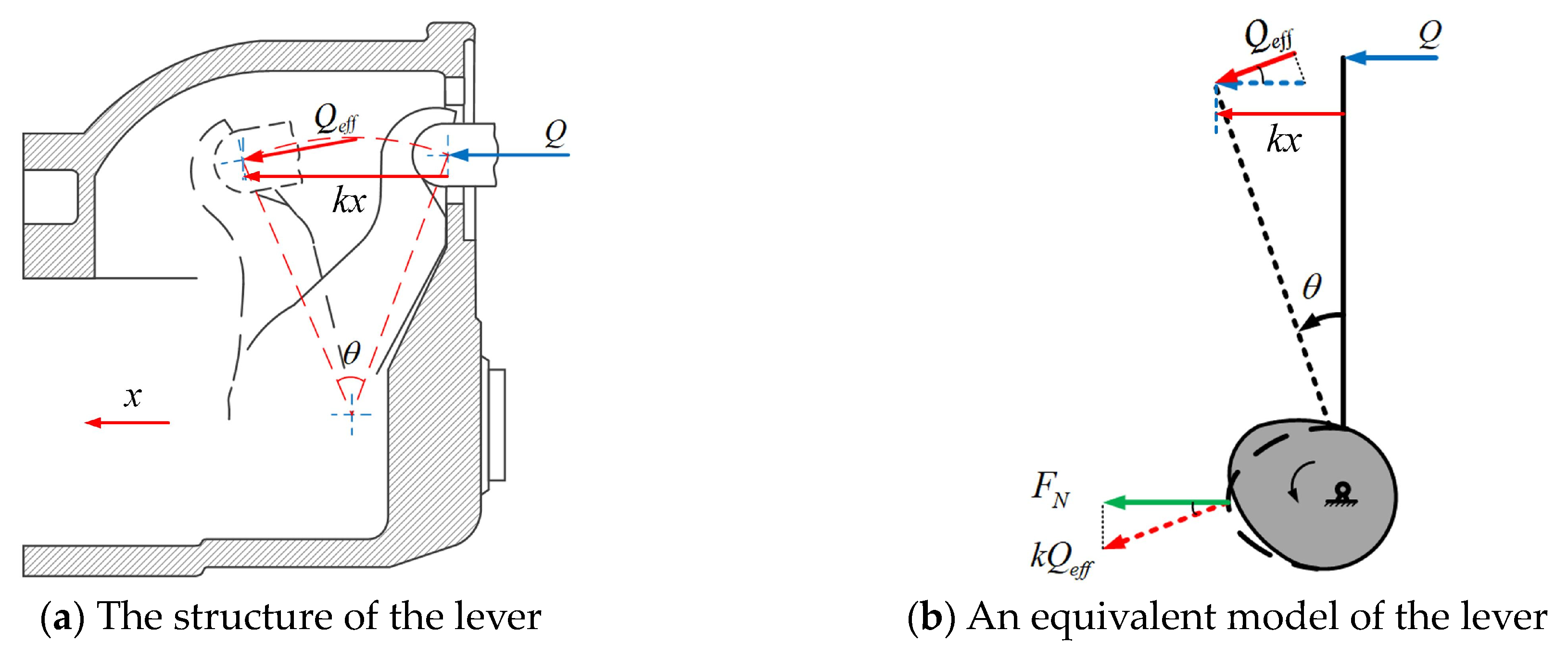
Although the structural scheme of the EMB functional prototype has advantages, it also presents significant issues: according to the “lever principle”, the lever 5 inside the caliper, while amplifying the axial thrust output by the push rod 4, also “inversely” amplifies the displacement of the piston 6 and transmits it to the end of the motor output shaft 2. As shown in Figure 3, a simplified model of the force-amplifying lever 5 and piston 6 is presented:
It can be seen from the figure that if the displacement of the piston 6 is x, the displacement of the push rod 4, after being “inversely” amplified by the lever 5, is kx. Through the screw mechanism 3 and gear mechanism 2, the rotational angle of the motor output shaft will also be amplified k times. This means that for the EMB to eliminate the brake clearance and reach the maximum braking pressure within a short time, the scheme using the force-amplifying lever requires the motor to have a wider speed range. This undoubtedly increases the difficulty of the motor design and manufacturing costs of the EMB.
Additionally, the axial dimension of the EMB prototype is comparable to the dimensions of the pneumatic brake equipped in the rear axle (approximately 670 mm). The excessive axial dimension leads to reduced space utilization, making it suitable only for the rear axle installation of vehicles.

2.3. The New Structural Scheme of the EMB

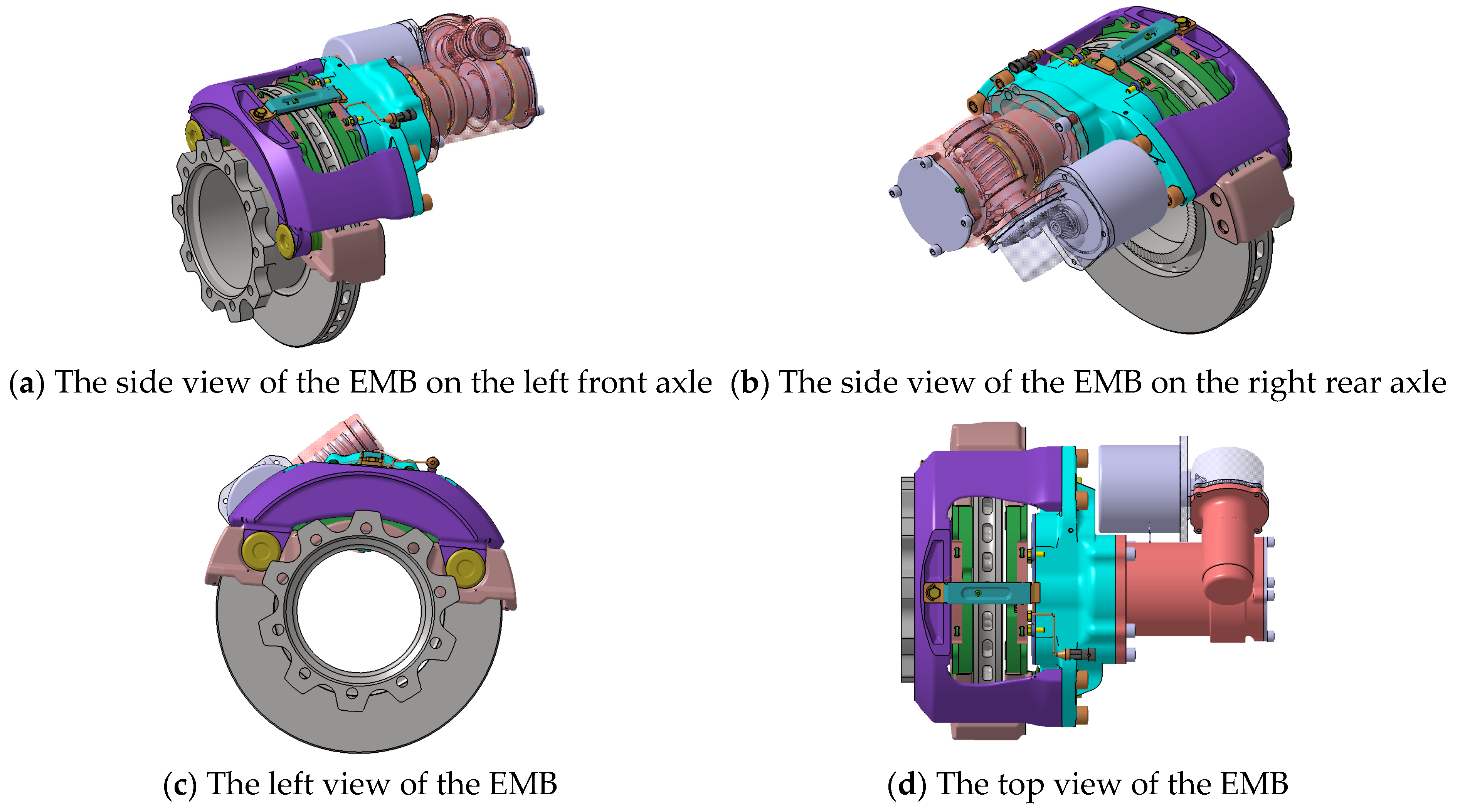
To address these issues, we further propose a new structural scheme of the EMB, meeting the braking requirements of the target vehicle. The 3-D model is shown in Figure 4.
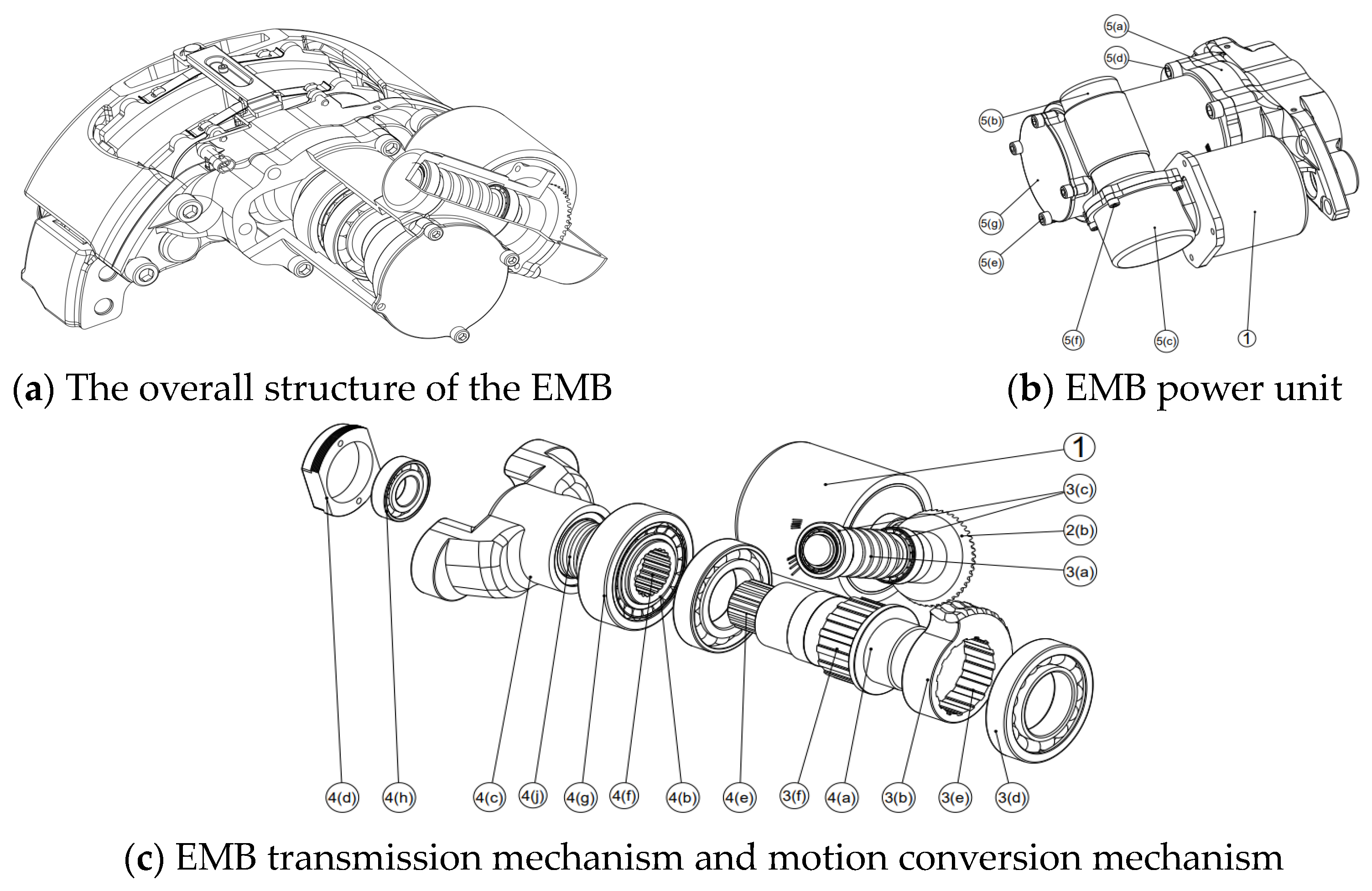
The structural diagram of the scheme (Figure 5) is as follows:
Overall, the new EMB consists of three parts: a power unit composed of an actuating motor, primary transmission mechanism, secondary transmission mechanism, and split-type motion conversion mechanism; a brake disc; and an improved floating caliper. The power unit is mounted inside a fixed housing and divided into three housings of the front, middle, and rear. The rear housing contains the primary transmission mechanism; the middle housing integrates the secondary transmission mechanism and the split-type motion conversion mechanism; and the front housing contains the clamping nut and the limit nut. The motor is bolted to the rear housing, the front housing is bolted to the caliper, and three housings are fixed to each other. The primary transmission mechanism consists of an arc-toothed bevel gear; the secondary transmission mechanism consists of a worm gear and worm; and the split-type motion conversion mechanism consists of a worm shaft, a lead screw shaft, and a clamping nut. The worm, worm shaft, and lead screw shaft are mounted in their respective housings through bearings.
The principle of the EMB is illustrated below using the example of applying braking: When the EMB receives a braking signal, the servo motor begins to operate. The torque is transmitted from the motor to the small helical bevel gear. The large helical bevel gear, which meshes with the small helical bevel gear, is connected to the worm through a flat key and fixed by bolts. Another end of the worm meshes with the worm gear, which is mounted on one side of the worm gear shaft, allowing the torque to be transmitted to the worm gear. After the torque is transmitted to the lead screw shaft via the worm gear shaft, it is further converted into the linear motion of the clamping nut through the pair of rolling screws. This linear motion pushes the friction linings to clamp the brake disc and generates clamping force.
To prevent the excessive movement of the clamping nut, a limit nut is used to restrict its maximum displacement. Additionally, to reduce the size of the EMB, the worm gear is designed with an incomplete tooth profile to match the angle of rotation during EMB operation.
Figure 6 compares the pneumatic disc brake of a mainstream brake, the EMB prototype, and the new EMB scheme. As shown in the figure, the axial length of the pneumatic disc brake is 627.7 mm, the axial length of the EMB prototype is 674.7 mm, and the axial length of the new EMB is 517 mm (with the axial length of the power unit being only 224 mm). Therefore, the new EMB structural scheme is 17.6% shorter than the pneumatic disc brake and 23.4% shorter than the EMB prototype.

3. The Dynamics Model of the EMB Actuator

Corresponding to the actuator, the EMB dynamics model used for clamping force control also contains four parts: a servo motor, transmission mechanism, conversion mechanism, and caliper. Furthermore, to describe the friction in the transmission and conversion mechanisms of the actuator, a friction model is introduced in addition to the above four parts. The overall structure of the dynamics model is shown in Figure 7.
The function of the caliper model is to apply the force between the friction lining and brake disc inversely to the motor, thereby balancing the motor’s output torque with the resistance torque. Therefore, the EMB model described in the figure is also referred to as a torque balanced model.

3.1. Control-Oriented Servo Motor Model

To simplify the analysis, this study adopts an idealized permanent magnet synchronous motor (PMSM) model as the servo motor and assumes the following conditions [23]: the magnetic saturation effect of the motor is ignored; energy losses due to eddy currents and hysteresis within the motor are neglected; and the currents in the PMSM are symmetrical three-phase sinusoidal currents. Based on these assumptions, the mechanical motion equation of the motor can be derived as follows.
J d ω m d t = T e T L B ω m
where ω m represents the mechanical angular velocity of the motor, J denotes the moment of inertia, B is the damping coefficient, and T L stands for the load torque.
The complete decoupling of the three-phase PMSM mathematical model can be achieved through Clarke and Park transformations. In the synchronous coordinate system, the electromagnetic torque equation can be expressed as follows:
T e = 3 2 n p i q i d ( L d L q ) + ψ f
where T e represents the electromagnetic torque, n p is the number of pole pairs of the motor, i q and i d are the d-axis and q-axis components of the stator current, L d and L q are the d-axis and q-axis components of the stator inductance, and ψ f represents the flux linkage produced by the permanent magnet on the stator.

3.2. Transmission Mechanism Model

The transmission mechanism consists of bevel gears and worm gears. Among these, the bevel gear serves as the high-speed stage of the transmission mechanism and is connected to the output shaft of the PMSM. The worm gear further amplifies the torque before inputting into the conversion mechanism. Therefore, the dynamic model of the transmission mechanism can be simplified as follows:
T 2 = i 1 i 2 η 1 η 2 T 1 n 2 = n 1 i 1 i 2
where i 1 , i 2 represent the transmission ratio of the bevel gear, η 1 , η 2 denote the transmission efficiency between the bevel gears and worm gears, T 1 , T 2 are the input and output torques, respectively, and n 1 , n 2 are the input and output speeds.

3.3. Conversion Mechanism Model

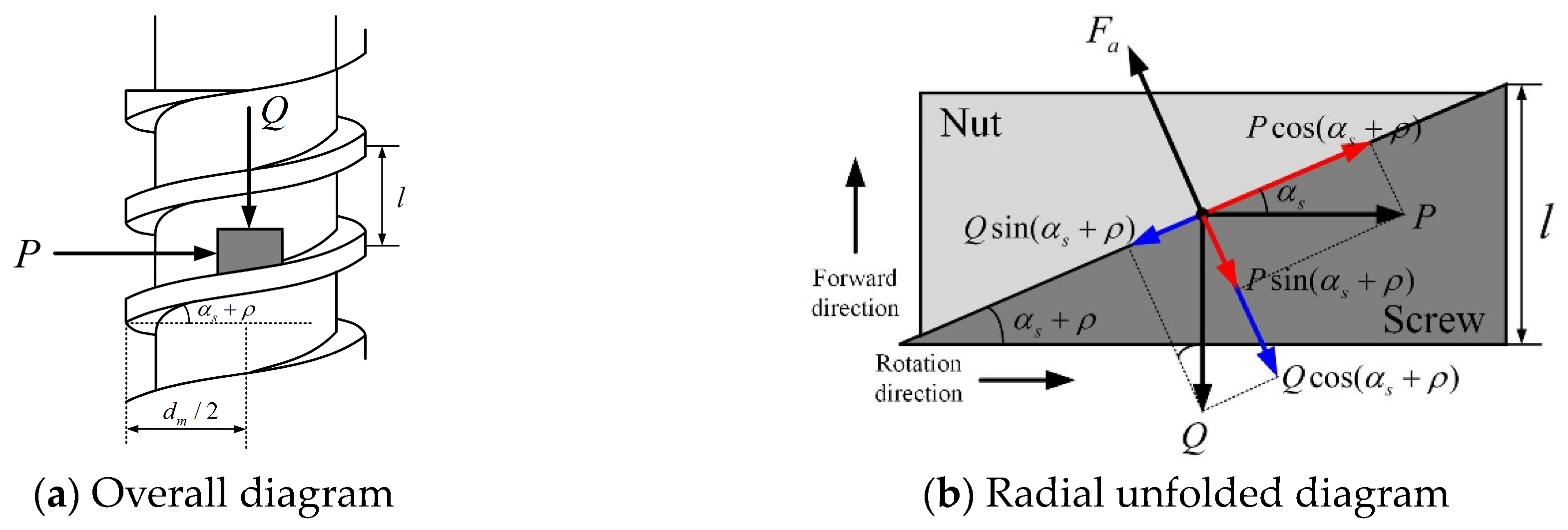
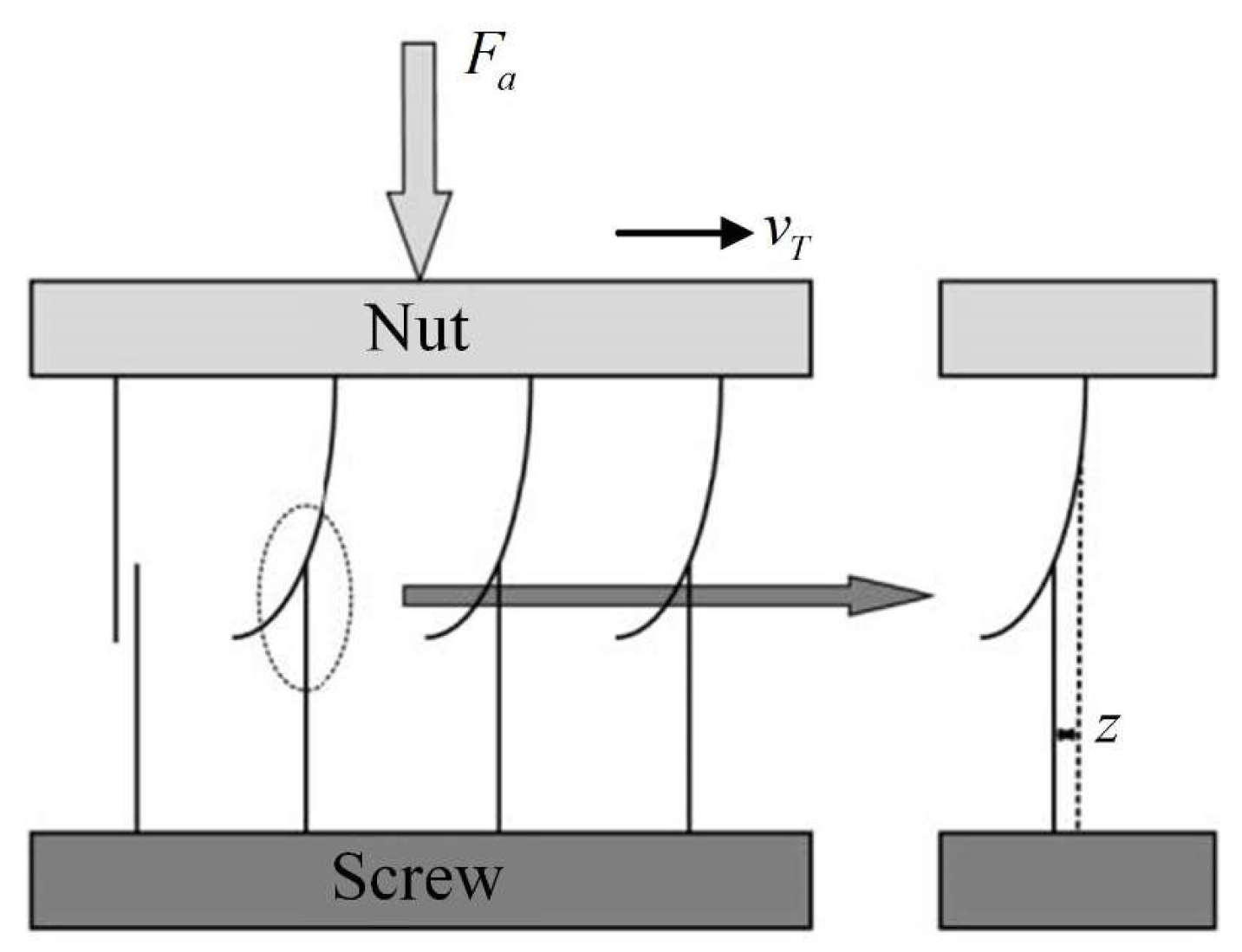
The conversion mechanism in the proposed EMB actuator employs a pair of ball screws, with the screw as the driving element and the nut as the driven element. Figure 8 illustrates a force analysis diagram of the ball screw pair [24]; the nut rotates under the input torque and drives the screw axially outward through the thread mechanism.
According to Figure 9, the axial thrust output of the screw is
Q = 2 π η T i l
If the friction between the screw and nut is neglected, the relationship between the input torque and the axial thrust Q is as follows:
T i η = Q d m 2 tan ( α s + ρ )
where α s represents the thread helix angle; ρ denotes the equivalent friction angle of the thread mechanism; d m stands for the nominal diameter of the screw; l represents the lead of the thread mechanism; η signifies the efficiency of the thread mechanism.
Furthermore, the axial travel of the screw is
x a = θ m l 2 π
where θ m represents the nut angle (which is also the rotor angle of the motor).

3.4. Friction Model

The LuGre friction model is introduced to describe the friction in the transmission and conversion mechanisms, and the model is shown in Figure 9.
The LuGre friction model is shown in Equation (7)
F f , m = σ 0 z + σ 1 z · + σ 2 v T z · = v T σ 0 v T g ( v T ) z g ( v T ) = F c + ( F s F c ) e ( v T / v s ) 2
where   F f , m   represents the friction force of the mechanisms;   σ 0   is the stiffness coefficient;   σ 1   is the viscous damping coefficient;   σ 2   is the viscous friction coefficient;   g ( v T )   is the Stribeck function;   F c   is the Coulomb friction force;   F s   is the static friction force;   v s   is the Stribeck velocity;   v T   is the relative velocity of the mechanism parts.
The parameters in the equation are shown in Table 2.
Above all, the friction torque of the transmission and conversion mechanisms is
T f , m = F f , m d m 2

3.5. Caliper Model

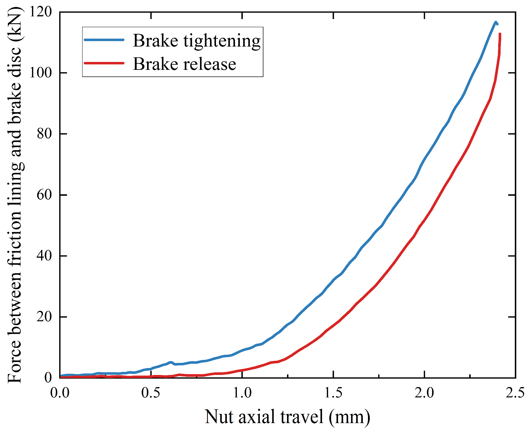
The caliper model is used to describe the relationship between the axial travel of friction lining and the clamping force applied to the brake disc. This study further fits the caliper model through kinematic simulation, as shown in Equation (9).
F N = a 1 e x a b 1 c 1 2 + a 2 e x a b 2 c 2 2 + a 3 e x a b 3 c 3 2
The parameters in the equation are shown in Table 3.

4. Clamping Force Control Strategy Considering Contact Point

4.1. EMB Operation Process

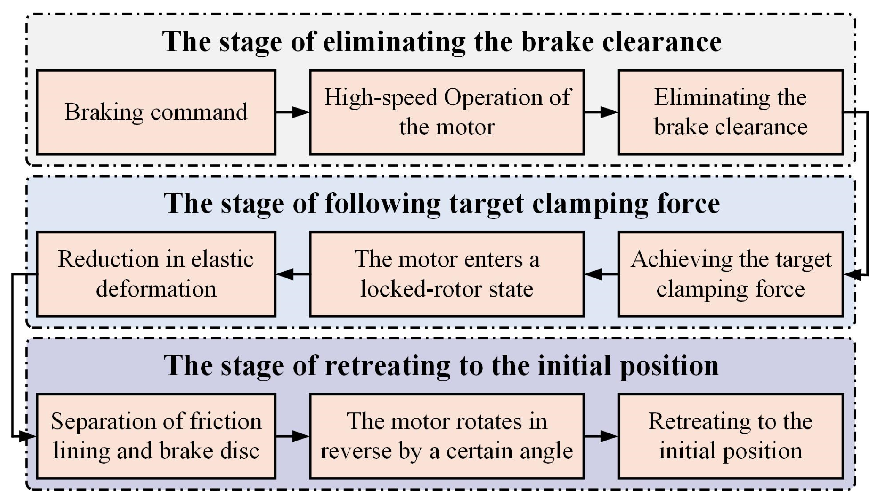
The operation process of the EMB is depicted in Figure 10. During a complete braking, the EMB comprises three critical operational stages: eliminating the brake clearance, following the target clamping force, and retreating to the initial position.
  • The stage of eliminating the brake clearance
During this stage, the motor drives the friction lining to move through the transmission and conversion mechanisms for eliminating the brake clearance. Since substantial contact between the friction lining and brake disc has not occurred during this process, the resistance experienced by the motor can be negligible. Therefore, the motor operates at a higher speed during this stage, thereby shortening the response of the EMB.
2.
The stage of following target clamping force
The friction lining contacts with the brake disc after eliminating the brake clearance completely. The elastic deformation of the friction lining generates corresponding clamping force in this stage. After the target clamping force is achieved, the motor enters a locked-rotor state and continuously outputs a constant torque. As the target clamping force decreases, the motor reverses, and the elastic deformation of the friction lining is gradually reduced.
3.
The stage of retreating to the initial position
To prevent abnormal wear between the friction lining and brake disc, after the brakes are completely released, the motor must rotate in reverse by a certain angle. This action establishes a fixed brake clearance between to prepare for the next braking.

4.2. Clamping Force Control Architecture

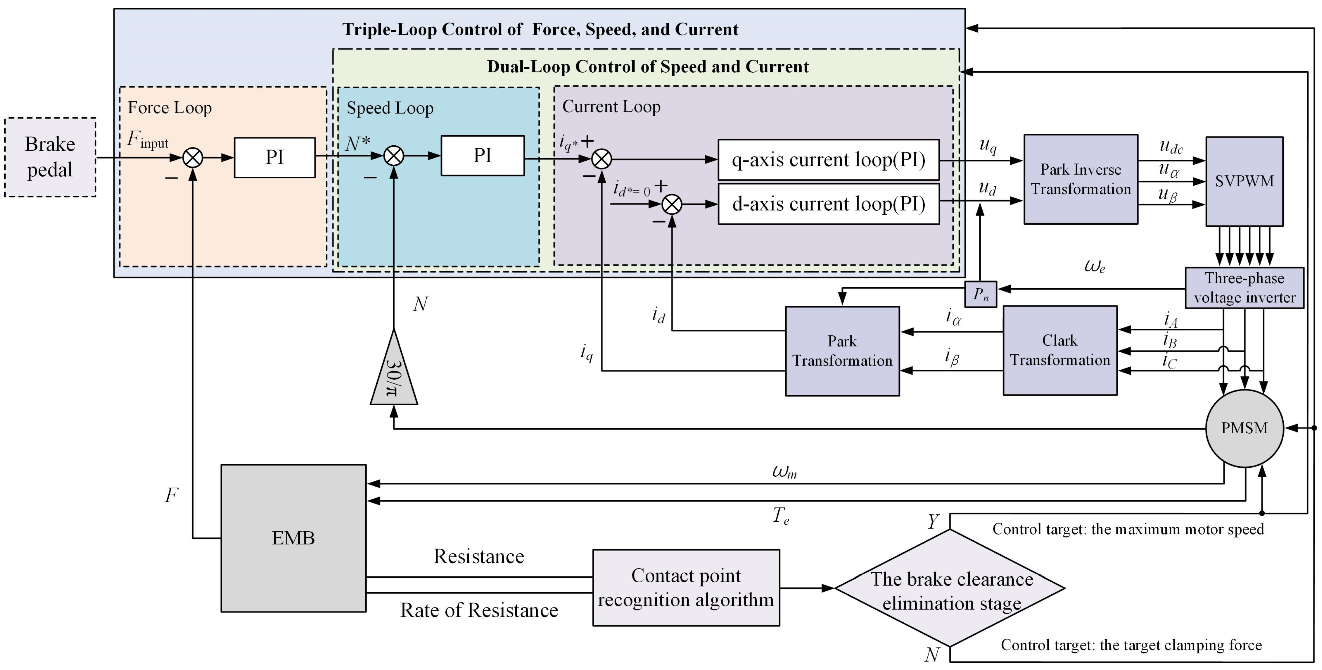
This study proposes a multi-mode cascaded closed-loop control architecture considering the contact point between the friction lining and brake disc, as depicted in Figure 11.
Generally, the architecture consists of two parts: the contact point recognition module and the cascaded control module based on the “clamping force—motor speed—motor current” scheme. Initially, the contact point recognition determines if the actuator is in the brake clearance elimination stage. If so, the motor operates at the maximum speed to rapidly move the friction lining and shorten the braking response. Once the brake clearance is eliminated, the target clamping force becomes the primary control objective, and the clamping force is controlled by adjusting the motor speed and current.
Specifically, within the cascaded control of “clamping force—motor speed—motor current”, the clamping force loop takes the error between the actual and target forces as input and determines the target motor speed based on the PI algorithm. The motor speed control loop takes the error between the actual and target speeds and determines the target motor current based on the PI algorithm. The input of current control is the actual current on the q-axis and d-axis, and the output of the loop is the reference voltage for the axes. Ultimately, the servo motor is driven by the Field-Oriented Control (FOC) strategy.

4.3. Recognition of Contact Point between Friction Lining and Brake Disc Based on Fuzzy Logic Algorithm

4.3.1. Principles of Contact Point Recognition

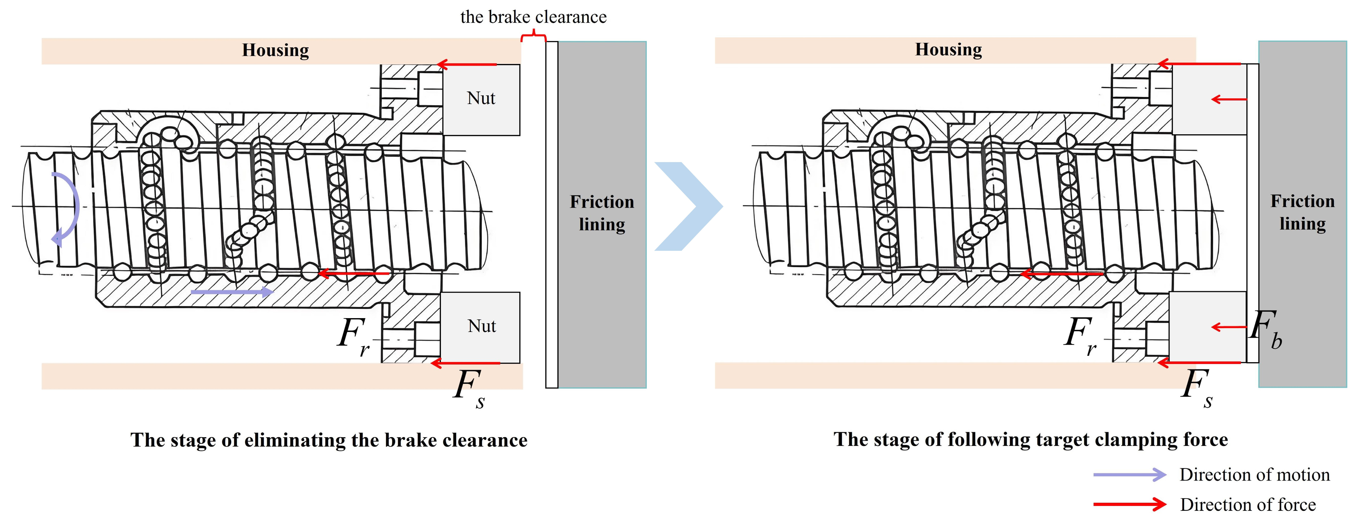
Through an analysis of the EMB principle, it is evident that the contact point between the friction lining and brake disc serves as the boundary for the stages of eliminating the brake clearance and following the clamping force. To further explore the principle and establish the method of contact point recognition, the micro-stages before and after brake clearance elimination are analyzed separately, as depicted in Figure 12.
Before the brake clearance is eliminated, the screw rotates under the drive of the servo motor, and the clamping nut drives the friction lining to move towards the brake disc. Assuming the rolling friction between the nut and screw is F r , and the sliding friction of the housing on the nut is F s , the resistance acting on the nut is as follows:
F H = F s + F r
When the friction lining contacts with the brake disc after the brake clearance is completely eliminated, the pressure generated between them is the clamping force. At this point, in addition to F r and F s , the clamping nut also experiences a reactive force F b exerted by the friction lining in the opposite direction of the clamping force (equal in magnitude but opposite in direction). Therefore, after completely eliminating the brake clearance, the resistance acting on the clamping nut is as follows:
F H = F s + F r + F b
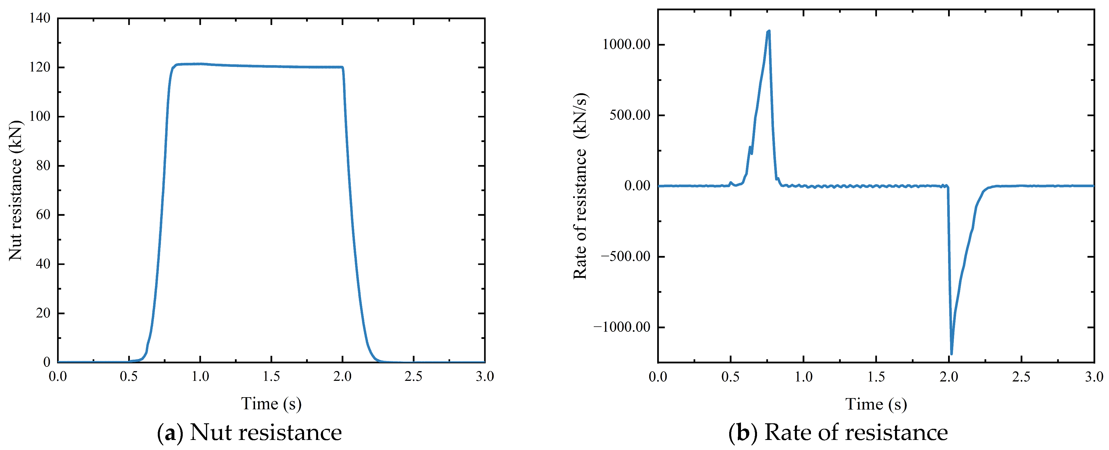
Assuming the rolling friction   F r   between the clamping nut and the screw and the sliding friction   F r   between the housing and the nut remain relatively constant, the resistance experienced by the nut and its rate will abruptly change at the moment when the friction lining contacts the brake disc. Therefore, this study will determine the contact moment by identifying the resistance and the rate experienced by the clamping nut.

4.3.2. Contact Point Recognition Strategy

Based on the above analysis, this study identifies the inflection moments of the nut resistance and its rate based on the fuzzy logic algorithm and uses the identified moment to determine the contact point between the friction lining and brake disc. Fuzzy logic algorithms do not require precise mathematical models to describe the controlled system, which increases control flexibility and is particularly useful for handling uncertain and ambiguous input data [25,26,27].
  • Membership Function
The size of the membership function determines the degree to which each element in the fuzzy domain belongs to a membership function. This study adopts a Mamdani fuzzy logic controller, where the input parameters are the resistance and its rate of the nut, and the output parameter is the likelihood of contact points.
Specifically, the resistance on the nut is subdivided into eight fuzzy sets, “Az”, “Bz”, “Cz”, “Dz”, “Ez”, “Fz”, “Gz”, and “Hz”, and these represent the nut resistance ranges of [0, 1], [0.5, 1.5], [1, 2], [1.5, 2.5], [2, 3], [2.5, 3.5], [3, 4], and [3.5, 4.5] kN, respectively.
The resistance rate is also divided into eight fuzzy sets, “Ad”, “Bd”, “Cd”, “Dd”, “Ed”, “Fd”, “Gd”, and “Hd”, and these represent the ranges of [−3, 26], [26, 70], [70, 105], [105, 140], [140, 175], [175, 210], [210, 245], and [245, 280] kN/s, respectively.
The likelihood of contact points is subdivided into eight fuzzy sets, “VL”, “QL”, “L”, “ML”, “M”, “MG”, “MH”, and “H”, ranging from “very low”, “low”, “moderate-low”, “moderate”, “moderate-high”, “high”, to “very high”, and these represent the probabilities that the friction lining and brake disc contacted.
Ultimately, the input–output sets are represented using a triangular membership function according to the principles of the EMB, as shown in Figure 13.
2.
Fuzzy Rules
Fuzzy rules define the mapping relationship between input and output variables with a fuzzy logic system. This study establishes 64 fuzzy rules, as shown in Table 4.
Relying on the membership functions and fuzzy rules, it is possible to estimate the likelihood of the contact point in each sampling period.

4.4. Clamping Force Control Considering the Contact Point

4.4.1. Clamping Force and Motor Speed Loops: PI Algorithm

The EMB characteristics may change under different stages. The PI controller can adapt to these changes by adjusting the system dynamic characteristics. Therefore, this study implements the regulation of clamping force and motor speed based on the PI algorithm. The expression of the PI algorithm is
u ( t ) = K p e ( t ) + K i 0 t e ( τ ) d τ
where u t is the output, e t is the error, and K p and K i are the parameters needed to be tuned in the algorithm. Moreover, the role of K p in the algorithm is to speed up the adjustment and reduce the steady-state error, but if K p is too large, it will increase the overshoot and prolong the adjustment period. The role of K i is to eliminate steady-state errors. For the clamping force loop, e t is the error between the actual force and the expected value, and u t is the expected motor speed. For the motor speed loop, e t is the error between the actual speed and the expected value, and u t is the expected motor current.

4.4.2. The Motor Current Loop

According to the principle of the PMSM, the armature current is determined by the voltage. Therefore, the control strategy of the motor current loop is to design a closed-loop control function based on voltage, ensuring that the armature current can quickly and accurately track the control target. Currently, the FOC based on the Space Vector Pulse Width Modulation (SVPWM) strategy is widely adopted to regulate the motor current. Since the SVPWM was introduced in the industry, its technical details are not further provided in this manuscript [28,29].

5. A Simulation Analysis of the Strategy

5.1. Contact Point Identification Method

The resistance and its rate of the nut during a braking process are shown in Figure 14.
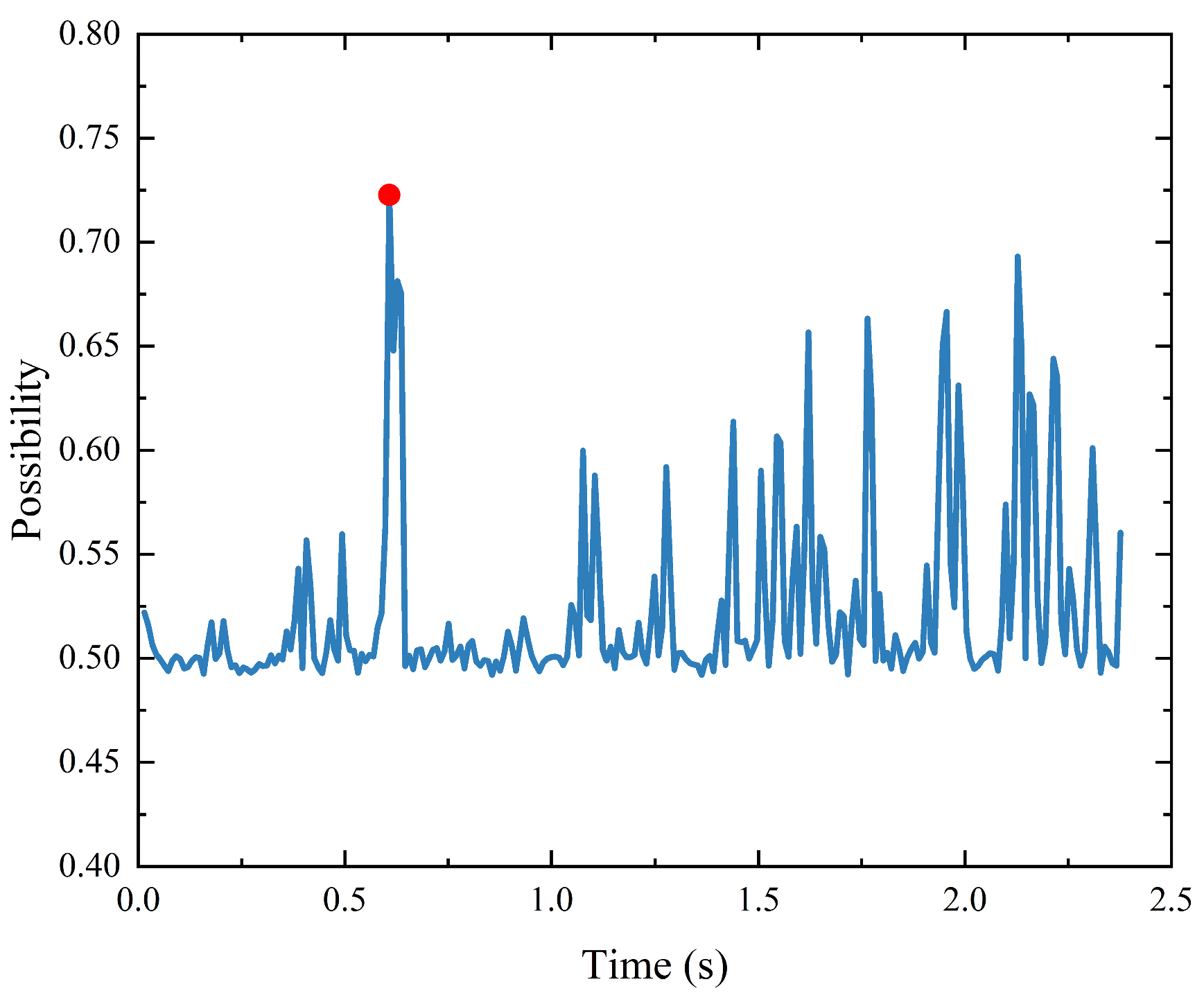
According to the contact point identification strategy established in Section 4.3.2, the resistance and its rate of the nut are used as inputs. The contact point between the friction lining and the brake disc is identified based on the MATLAB Fuzzy toolbox, and the results are shown in Figure 15. The characteristic of the caliper determined by Equation (9) and Table 2 is shown in Figure 16.
From Figure 15, it can be seen that the probability of the contact point is the highest at approximately 0.62 s after fuzzy reasoning. Combining this with Figure 14, it is observed that the nut resistance is 3.89 kN, and the rate of resistance is 189.27 kN/s at this moment. These results are generally consistent with the caliper characteristics shown in Figure 16. From the figure, it can be seen that the time for the actuator to completely eliminate the brake clearance is 0.62 s, and the axial travel of the nut is approximately 0.81 mm. Hence, the proposed method can accurately identify the contact point between the friction lining and the brake disc.

5.2. Clamping Force Control Strategy

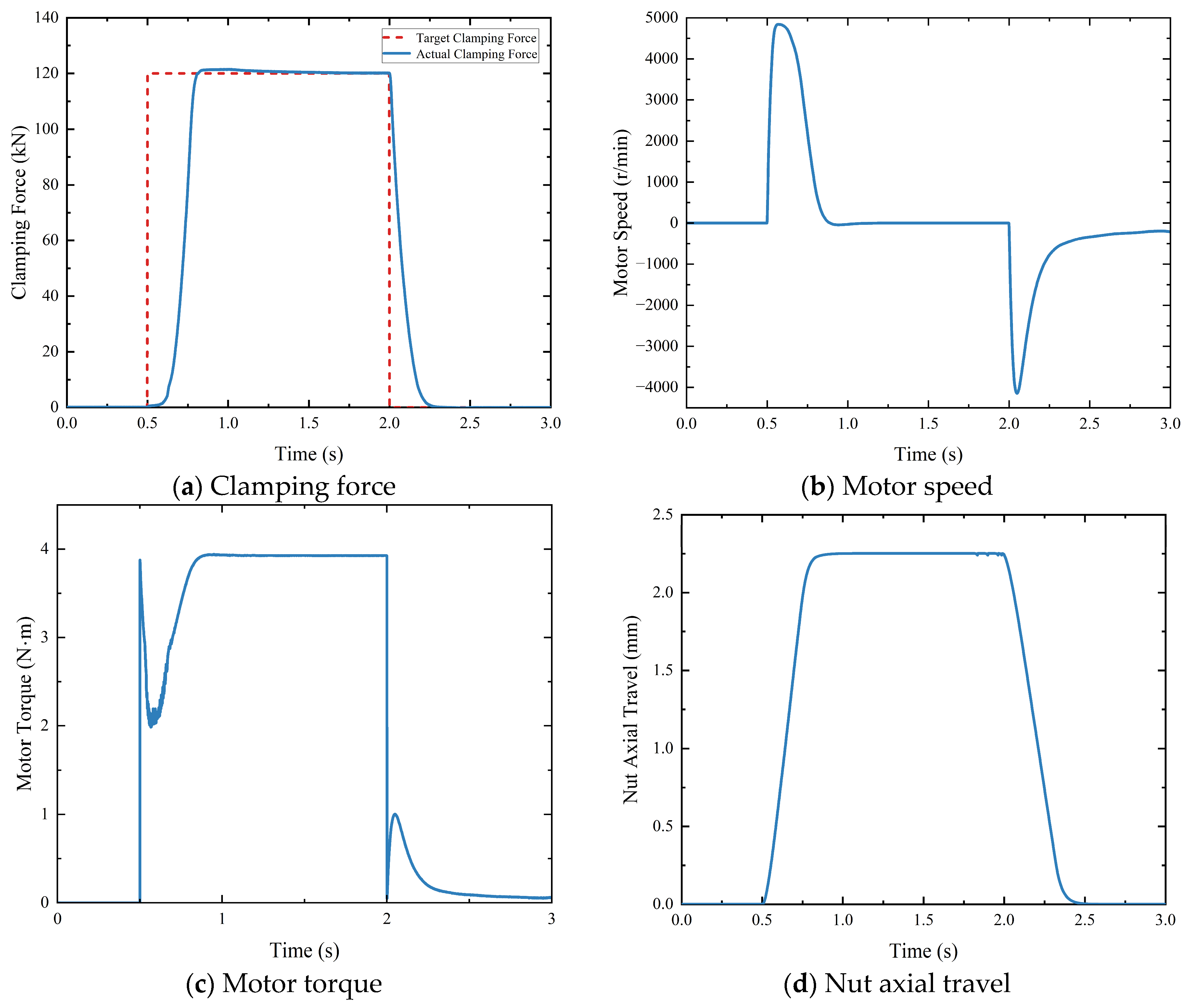
To verify the feasibility and effectiveness of the clamping force control strategy, this study simulates the dynamic characteristics of the EMB actuator under the step, pulse, ramp, and sinusoidal signals of the expected clamping force.
  • Step signal of maximum clamping force
The simulation results of the step signal with the maximum clamping force are shown in Figure 17. Figure 17a,d depict the clamping force, nut axial travel, motor speed, and motor torque in this condition.
From Figure 17a, it can be seen that the clamping force starts from 0.62 s and reaches the maximum value of 120 kN at approximately 0.8 s, with a maximum clamping force response of about 0.3 s. From Figure 17b,c, the maximum motor speed is 4900 r/min, and the maximum torque is about 4 N m , indicating that the motor speed and torque output satisfy the expected requirements. From Figure 17d, the maximum axial travel of the nut when reaching the target clamping force is 2.2 mm.
2.
Pulse signal of various amplitude analysis
The simulation results of the clamping force under pulse signals of various amplitudes are shown in Figure 18. It can be seen from the figure that the EMB can achieve a rapid response to different target clamping forces, satisfying the design requirements.
3.
Ramp signal
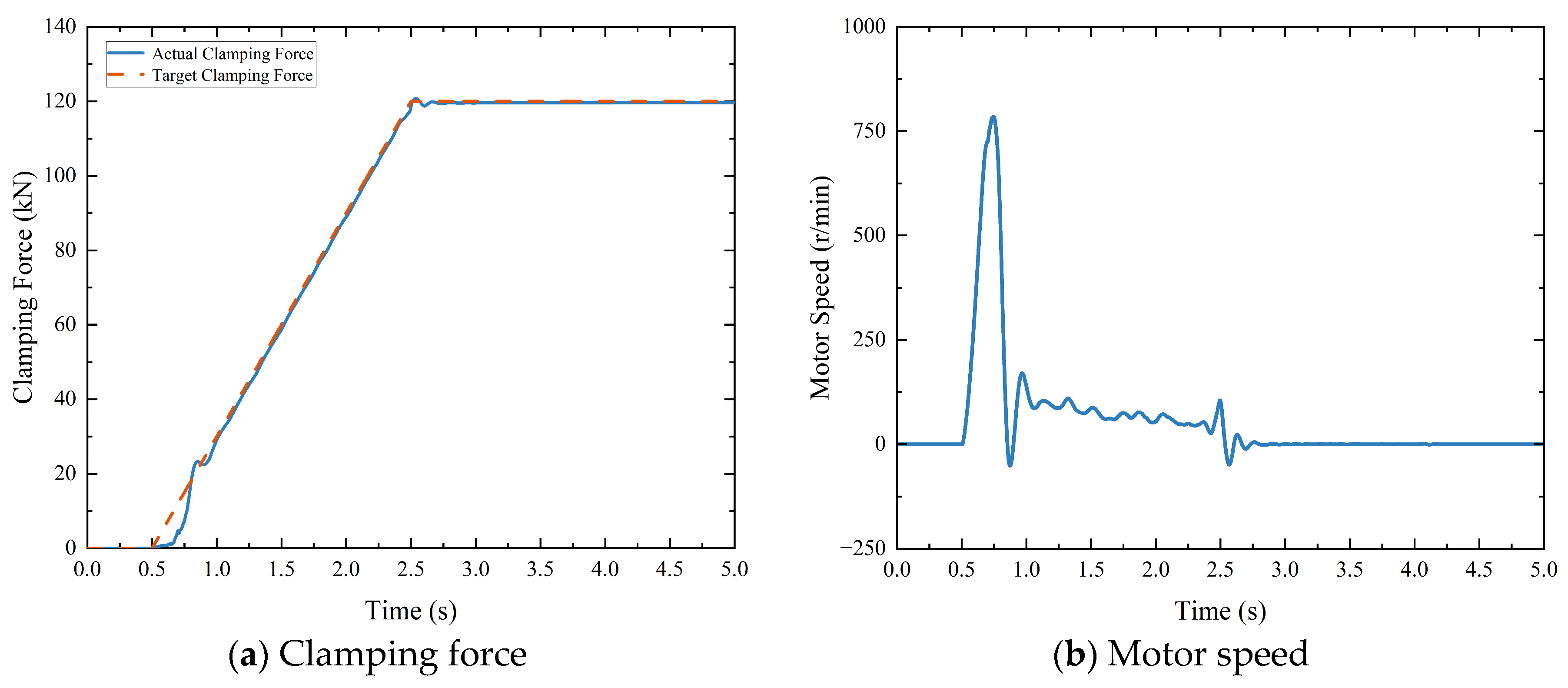
The simulation results of clamping force tracking performance under a ramp signal are shown in Figure 19. It can be seen from the figure that the clamping force rises along with the target signal until it reaches the maximum value after the brake clearance is completely eliminated. In the first 0.5 s, there is always a certain error between the actual clamping force and the target value. A possible reason for this error is that the brake clearance has not yet been eliminated. Once the brake clearance is completely eliminated, the error is almost zero.
4.
Sinusoidal signal
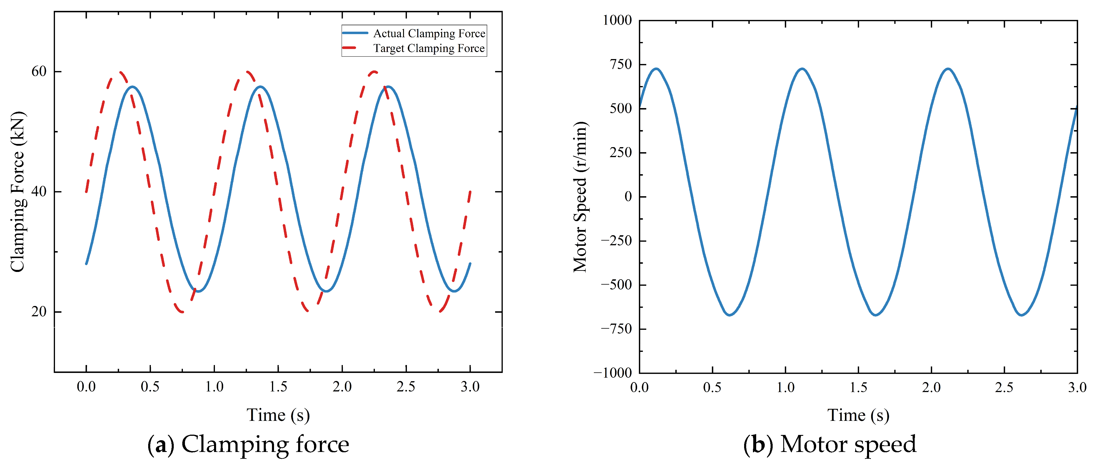
The target clamping force is adjusted to a sinusoidal signal (with a period of 1 s and an amplitude of 40 kN), and the simulation results are shown in Figure 20. Due to the inertia of the motor and transmission mechanism, there is a certain degree of delay and attenuation in the clamping force while tracking the target signal. This delay is particularly evident during the decreasing phase of the target signal, and the signal attenuation mainly occurs as it approaches a peak or trough.

6. Conclusions

Currently, most EMB schemes are only suitable for passenger cars, and their maximum clamping force is insufficient to satisfy the braking demands of commercial vehicles. Additionally, previous studies on clamping force control are largely based on the EMB equipped with sensors. Due to constraints in installation space and cost, sensorless EMBs are gradually gaining attention. To solve these issues, this study first designs a new sensorless EMB structural scheme suitable for commercial vehicles. Secondly, a clamping force control strategy that considers the identification of the contact point between the friction lining and brake disc is proposed. On this basis, an EMB simulation model is established based on MATLAB/Simulink, and the proposed contact point identification method and clamping force control strategy are analyzed through simulation. The results show the following:
  • Compared with a mainstream pneumatic disc brake, the axial length of the EMB actuator proposed in this study is reduced by 17.6%.
  • The contact point identification method can accurately identify the contact point between the friction lining and brake disc.
  • The clamping force control strategy enables the EMB actuator to achieve the rapid response, accurate tracking, and stable maintenance of the target signal. Specifically, the time to eliminate brake clearance is 0.5 s, the maximum clamping force response is 0.3 s, and the steady-state error is less than 1 kN.
In fact, the friction lining and disc temperature variations as well as friction lining wear will have a parental effect on the dynamic response characteristics of the EMB [30,31]. Next, we will conduct a further study on the issues of the temperature rise and wear of the friction lining during braking, as well as the hardware-in-the-loop tests and real vehicle validation of the EMB actuator.

Author Contributions

Conceptualization, Y.M. and T.W.; methodology, Y.M.; software, Y.M.; validation, Y.M. and T.W.; formal analysis, Y.M. and T.W.; investigation, T.W. and J.R.; resources, T.W.; data curation, Y.M.; writing—original draft preparation, Y.M.; writing—review and editing, T.W. and Y.M.; visualization, T.W.; supervision, T.W.; project administration, X.Y., J.P. and L.C.; funding acquisition, T.W. All authors have read and agreed to the published version of the manuscript.

Funding

This research was funded by the Project of Central Guidance for Local Scientific and Technological Development of Hubei with grant No. 2022BGE248, the Open Foundation of Key Laboratory of Automotive Power Train and Electronics (Hubei University of Automotive Technology) with grant No. ZDK1202204, and the PhD Scientific Research Foundation of Hubei University of Automotive Technology with grant No. BK202214.

Data Availability Statement

The data presented in this study are available in this article.

Conflicts of Interest

The authors declare no conflicts of interest.

References

  1. Fang, Z.; Wang, J.; Liang, J.; Yan, Y.; Pi, D.; Zhang, H.; Yin, G. Authority Allocation Strategy for Shared Steering Control Considering Human-Machine Mutual Trust Level. IEEE Trans. Intell. Veh. 2023, 9, 1–14. [Google Scholar] [CrossRef]
  2. Xu, B.; Ban, X.J.; Bian, Y.; Li, W.; Wang, J.; Li, S.E.; Li, K. Cooperative Method of Traffic Signal Optimization and Speed Control of Connected Vehicles at Isolated Intersections. IEEE Trans. Intell. Transp. Syst. 2019, 20, 1390–1403. [Google Scholar] [CrossRef]
  3. Wu, J.; Zhang, H.; He, R.; Chen, P.; Chen, H. A Mechatronic Brake Booster for Electric Vehicles: Design, Control, and Experiment. IEEE Trans. Veh. Technol. 2020, 69, 7040–7053. [Google Scholar] [CrossRef]
  4. Keller, F. Electromagnetic Wheel Brake Device. U.S. Patent US6536561 B1, 25 March 2003. [Google Scholar]
  5. Cao, C.-T.; Hofmann, D.; Vollert, H.; Nagel, W.; Foitzik, B.; Goetzelmann, B. Self-Boosting Electromechanical Friction Brake. EP 2057385A1, 13 May 2009. [Google Scholar]
  6. 2006-1-3196; The Electronic Wedge Brake-EWB. SAE International: Warrendale, PA, USA, 8 October 2006.
  7. 2007-1-866; Modeling and Control of a Single Motor Electronic Wedge Brake. SAE International: Warrendale, PA, USA, 16 April 2007.
  8. 2006-1-298; Simulation in the Development of the Electronic Wedge Brake. SAE International: Warrendale, PA, USA, 3 April 2006.
  9. Zhang, M.; Song, J. A Review of Electromechanical Brake (EMB) System. Mech. Sci. Technol. Aerosp. Eng. 2005, 24, 208–211. [Google Scholar]
  10. Gong, X.; Ge, W.; Yan, J.; Zhang, Y.; Gongye, X. Review on the Development, Control Method and Application Prospect of Brake-by-Wire Actuator. Actuators 2020, 9, 15. [Google Scholar] [CrossRef]
  11. Li, C.; Zhuo, G.; Tang, C.; Xiong, L.; Tian, W.; Qiao, L.; Cheng, Y.; Duan, Y. A Review of Electro-Mechanical Brake (EMB) System: Structure, Control and Application. Sustainability 2023, 15, 4514. [Google Scholar] [CrossRef]
  12. Lars, S. A Method and Arrangement for Parking Braking at A Disc Brake. WO 2005/031184 A1, 7 April 2005. [Google Scholar]
  13. Li, J.; Wang, M.; He, R.; Zhang, J. A Design of Electromechanical Brake System Triple-Loop Controllers Using Frequency Domain Method Based on Bode Plote. In Proceedings of the Proceedings 2011 International Conference on Transportation, Mechanical, and Electrical Engineering (TMEE), Changchun, China, 16–18 December 2011; IEEE: New York, NY, USA, 2011; pp. 795–798. [Google Scholar]
  14. Jo, C.; Hwang, S.; Kim, H. Clamping-force control for electromechanical brake. IEEE Trans. Veh. Technol. 2010, 59, 3205–3212. [Google Scholar] [CrossRef]
  15. Line, C.; Manzie, C.; Good, M.C. Electromechanical Brake Modeling and Control: From PI to MPC. IEEE Trans. Control Syst. Technol. 2008, 16, 446–457. [Google Scholar] [CrossRef]
  16. Saric, S.; Bab-Hadiashar, A.; Walt, J.V.D. Estimating Clamp Force for Brake-by-Wire Systems: Thermal Considerations. Mechatronics 2009, 19, 886–889. [Google Scholar] [CrossRef]
  17. Lindvai-Soos, D.; Horn, M. Modelling, Control & Implementation of an Electro-Mechanic Braking Force Actuator for HEV and EV. IFAC Proc. Vol. 2013, 46, 620–625. [Google Scholar]
  18. Park, G.; Choi, S.; Hyun, D. Clamping force estimation based on hysteresis modeling for electro-mechanical brakes. Int. J. Automot. Technol. 2017, 18, 883–890. [Google Scholar] [CrossRef]
  19. Chen, Q.; Lv, Z.; Tong, H.; Zeng, D.; Ouyang, L.; Liu, Q. Study on Multi-Closed Loop Control of Electro-Mechanical Braking for Electric Vehicles Based on Clamping Force. Proc. Inst. Mech. Eng. Part D J. Automob. Eng. 2023. [Google Scholar] [CrossRef]
  20. Eum, S.; Choi, J.; Park, S.-S.; Yoo, C.; Nam, K. Robust Clamping Force Control of an Electro-Mechanical Brake System for Application to Commercial City Buses. Energies 2017, 10, 220. [Google Scholar] [CrossRef]
  21. GB 12676-2014; Technical Requirements and Testing Methods for Commercial Vehicle and Trailer Braking Systems. Standards Press of China: Beijing, China, 2014.
  22. Kim, J.; Kwon, B.; Park, Y.; Cho, H.; Yi, K. A Control Strategy for Efficient Slip Ratio Regulation of a Pneumatic Brake System for Commercial Vehicles. Proc. Inst. Mech. Eng. Part D J. Automob. Eng. 2022, 236, 1546–1567. [Google Scholar] [CrossRef]
  23. Rafaq, M.S.; Midgley, W.; Steffen, T. A Review of the State of the Art of Torque Ripple Minimization Techniques for Permanent Magnet Synchronous Motors. IEEE Trans. Ind. Inform. 2024, 20, 1019–1031. [Google Scholar] [CrossRef]
  24. Liu, J.; Ma, C.; Wang, S. Precision loss modeling method of ball screw pair. Mech. Syst. Signal Process. 2020, 135, 106397. [Google Scholar] [CrossRef]
  25. Nguyen, A.-T.; Taniguchi, T.; Eciolaza, L.; Campos, V.; Palhares, R.; Sugeno, M. Fuzzy control systems: Past, present and future. IEEE Comput. Intell. Mag. 2019, 14, 56–68. [Google Scholar] [CrossRef]
  26. Sun, Y.; Wang, F.; Liu, Z.; Zhang, Y.; Chen, C.L.P. Fixed-Time Fuzzy Control for a Class of Nonlinear Systems. IEEE Trans. Cybern. 2022, 52, 3880–3887. [Google Scholar] [CrossRef]
  27. Pan, M.; Wang, H.; Zhang, C.; Xu, Y. Fuzzy Control for Aircraft Engine: Dynamics Clustering Modeling, Compensation and Hardware-in-Loop Experimental Verification. Aerospace 2024, 11, 610. [Google Scholar] [CrossRef]
  28. Guo, P.; Li, Y.; Lin, Z.; Li, Y.; Su, P. Characterization and Calculation of Losses in Soft Magnetic Composites for Motors with SVPWM Excitation. Appl. Energy 2023, 349, 121631. [Google Scholar] [CrossRef]
  29. Yang, G.; Hussain, H.; Li, S.; Zhang, X.; Yang, J.; Lee, C.H.T. Design and Analysis of Universal Natural Fault-Tolerant SVPWM Strategy with Simplified Fault Diagnosis for Multiphase Motor Drives. IEEE J. Emerg. Sel. Top. Power Electron. 2023, 11, 4340–4354. [Google Scholar] [CrossRef]
  30. Arricale, V.M.; Genovese, A.; Tomar, A.S.; Kural, K.; Sakhnevych, A. Non-Linear Model of Predictive Control-Based Slip Control ABS Including Tyre Tread Thermal Dynamics. Appl. Mech. 2022, 3, 855–888. [Google Scholar] [CrossRef]
  31. Devika, K.; Sridhar, N.; Patil, H.; Subramanian, S.C. Delay Compensated Pneumatic Brake Controller for Heavy Road Vehicle Active Safety Systems. Proc. Inst. Mech. Eng. Part C J. Mech. Eng. Sci. 2021, 235, 2333–2346. [Google Scholar] [CrossRef]
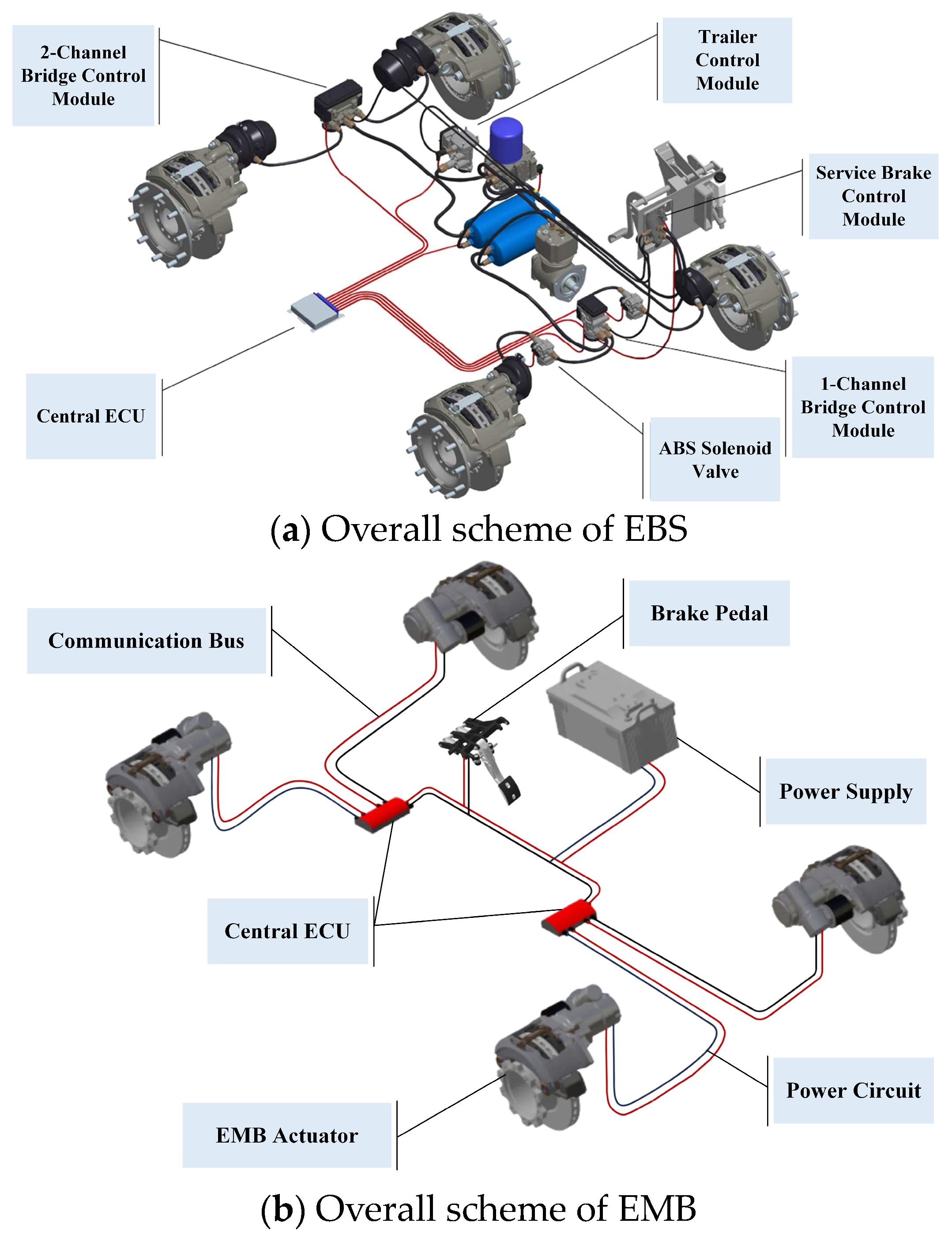
Figure 1. Overall scheme of EBS and EMB.
Actuators 13 00345 g001
Figure 2. The structural scheme of the electromechanical brake (EMB) based on the pneumatic disc brake. In this figure, 1—motor, 2—gear mechanism, 3—screw mechanism, 4—push rod, 5—lever, 6—piston, 7, 8—friction linings, 9—brake disc, 10—pressure sensor, 11—displacement sensor.
Actuators 13 00345 g002
Figure 3. An equivalent model of the brake caliper lever and cam mechanism. In this figure, Q is the axial thrust force of the push rod 4 on the output, Q e f f is the effective force of the push rod 4 on the lever 5, θ is the angle of rotation of the lever 5, k is the lever ratio, and F N is the vertical force between the friction lining and the brake disc.
Actuators 13 00345 g003
Figure 4. A 3-D model of the EMB.
Actuators 13 00345 g004
Figure 5. A schematic diagram of the EMB structure. In this figure, 1—servo motor, 2a—small helical bevel gear, 2b—large helical bevel gear, 2c—bevel gear fixing bolt, 2d—input shaft support bearing; 3a—worm, 3b—worm gear, 3c—worm shaft support bearing, 3d—worm gear shaft support bearing, 3e—worm gear spline, 3f—worm gear shaft spline; 4a—worm gear shaft, 4b—lead screw shaft, 4c—clamping nut, 4d—limit nut, 4e—worm gear torque transmission spline, 4f—lead screw shaft spline, 4g—lead screw bearing, 4h—lead screw positioning bearing, 4i—lead screw external thread, 4j—clamping nut internal thread; 5a—front housing, 5b—middle housing, 5c—rear housing, 5d—front and middle housing connection screws, 5e—middle housing end cover connection screws, 5f—middle and rear housing connection screws, 5g—middle housing end cover.
Actuators 13 00345 g005
Figure 6. A comparison of the schemes.
Actuators 13 00345 g006aActuators 13 00345 g006b
Figure 7. The control-oriented structure of the EMB.
Actuators 13 00345 g007
Figure 8. Force analysis of screw mechanism.
Actuators 13 00345 g008
Figure 9. LuGre friction model.
Actuators 13 00345 g009
Figure 10. The operational process of the EMB.
Actuators 13 00345 g010
Figure 11. Clamping force control architecture.
Actuators 13 00345 g011
Figure 12. An analysis of the force on the nut before and after the contact point.
Actuators 13 00345 g012
Figure 13. The membership function of inputs and output.
Actuators 13 00345 g013
Figure 14. Nut resistance and rate of resistance.
Actuators 13 00345 g014
Figure 15. Contact point identification results.
Actuators 13 00345 g015
Figure 16. Brake caliper characteristic curve.
Actuators 13 00345 g016
Figure 17. Simulation results of clamping force under step signal.
Actuators 13 00345 g017
Figure 18. Simulation results of clamping force under pulse signal.
Actuators 13 00345 g018
Figure 19. Simulation results of clamping force under ramp signal.
Actuators 13 00345 g019
Figure 20. Simulation results of clamping force under sine signal.
Actuators 13 00345 g020
Table 1. M3-type commercial vehicle body and wheel-related parameters.
CategoryParametersValueUnit
Vehicle MassFully Loaded Mass10,080kg
Curb Mass7690kg
WheelsMaximum Braking Torque16,500 N m
Effective Radius of Brake Disc173mm
Rolling Radius of Wheel51mm
BrakesBrake Clearance (Single Side)0.3~0.6mm
Friction Coefficient0.4/
Table 2. The parameters of the friction model.
ParametersSymbolValueUnit
Stiffness coefficient σ 0 0.001/
Viscous damping coefficient σ 1 0.001/
Viscous friction coefficient σ 2 0.001/
Stribeck velocity v s 0.8m/s
Coulomb friction F c 1N
Static friction F s 1.5N
Table 3. The fitted parameters of the caliper model.
Parameters a 1 b 1 c 1 a 2 b 2 c 2 a 3 b 3 c 3
Brake Tightening −422.355.1511.24 4.046 × 10 4 112.130.54000
Brake Release 9.715 × 10 11 63.393.911−23.2543.147.137142.249.0312.55
Table 4. Fuzzy rules.
ResistanceRate of Resistance
AdBdCdDdEdFdGdHd
AzVLVLQLQLLLMLML
BzVLQLQLLLMLMLM
CzQLQLLLMLMLMM
DzQLLLMLMLMMMG
EzLLMLMLMMMGMG
FzLMLMLMMMGMGMH
GzMLMLMMMGMGMHMH
HzMLMMMGMGMHMHH
Disclaimer/Publisher’s Note: The statements, opinions and data contained in all publications are solely those of the individual author(s) and contributor(s) and not of MDPI and/or the editor(s). MDPI and/or the editor(s) disclaim responsibility for any injury to people or property resulting from any ideas, methods, instructions or products referred to in the content.