
Development of a Small-Sized Urban Cable Conduit Inspection Robot


Abstract
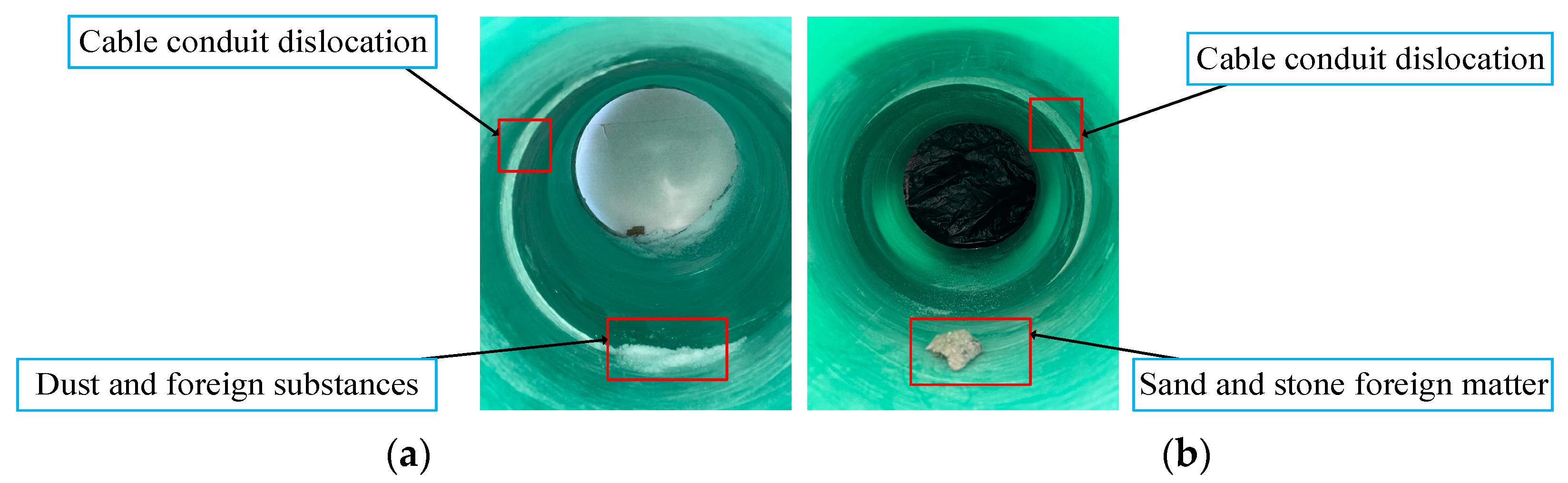
:1. Introduction
2. Functional Requirements and Technical Indicators
- Small Size: To ensure that the robot can fit into the confined space of the cable duct, it must be designed to be compact and small.
- Reasonable Drive: When the robot is moving in a circular cross-section cable duct, it is necessary to ensure that each driving force has sufficient power to avoid slipping.
- Comprehensive Inspection: Given the differences in conduit diameters, the inspection device needs to be appropriately adjustable to ensure effective defect detection.
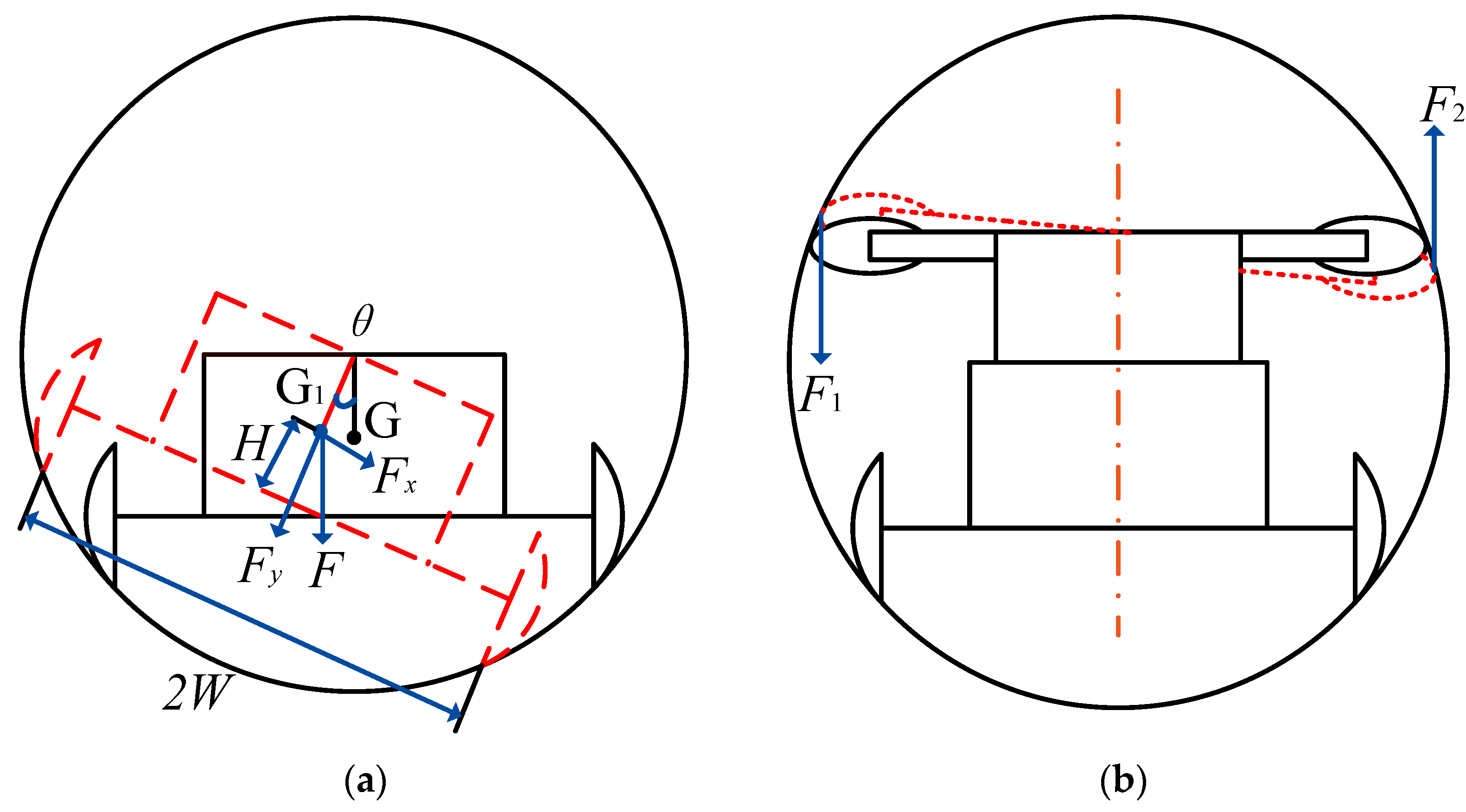
- Stable Operation: When a wheeled robot maneuvers within a circular cross-section cable conduit, the center of gravity often shifts away from the conduit’s center, leading to tilting. In severe instances, this can result in the robot rolling over. Hence, strict control of the tilt angle is crucial to prevent it from becoming excessive.
3. Robot Working Principle and Structural Design
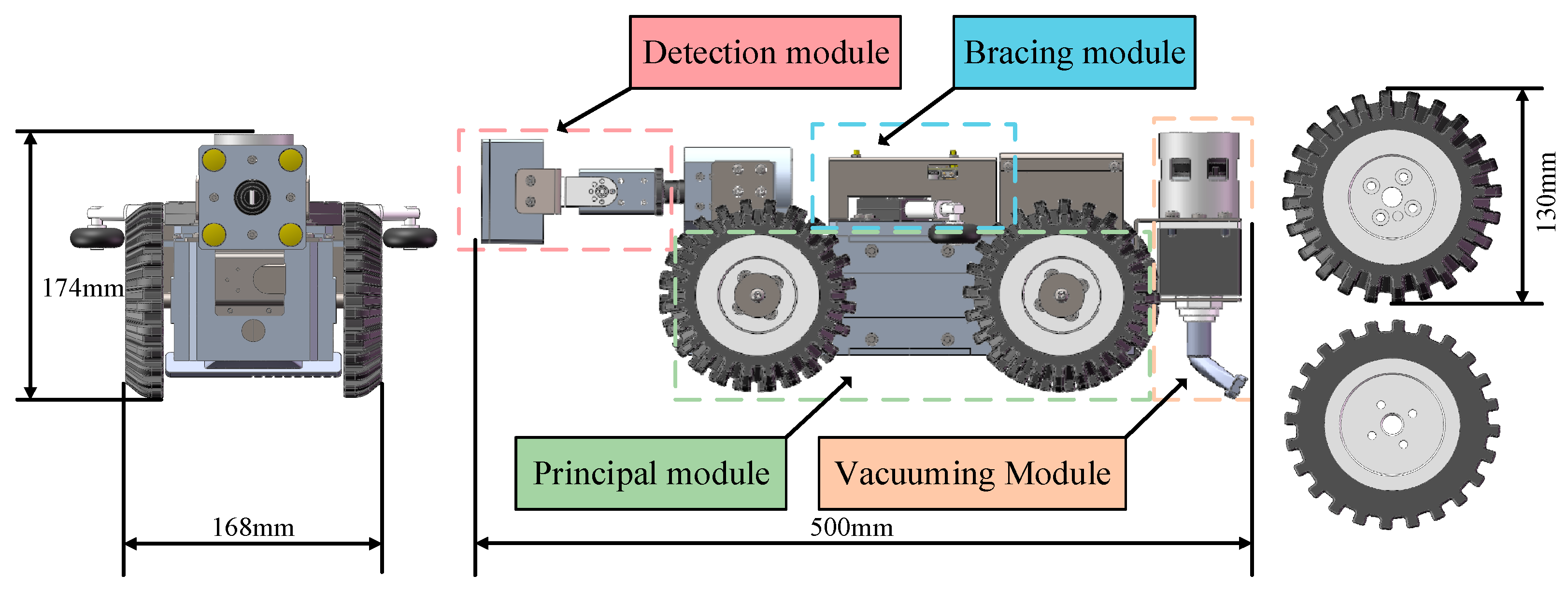
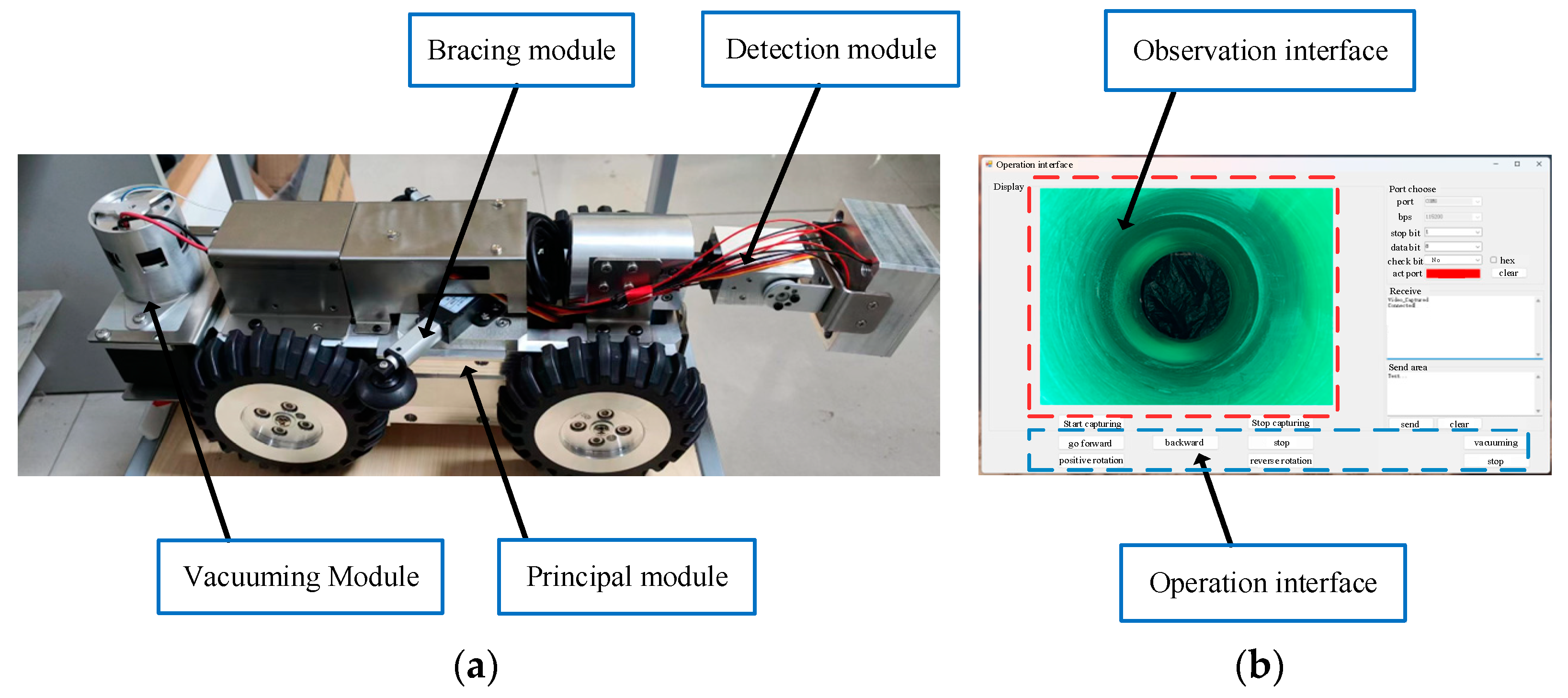
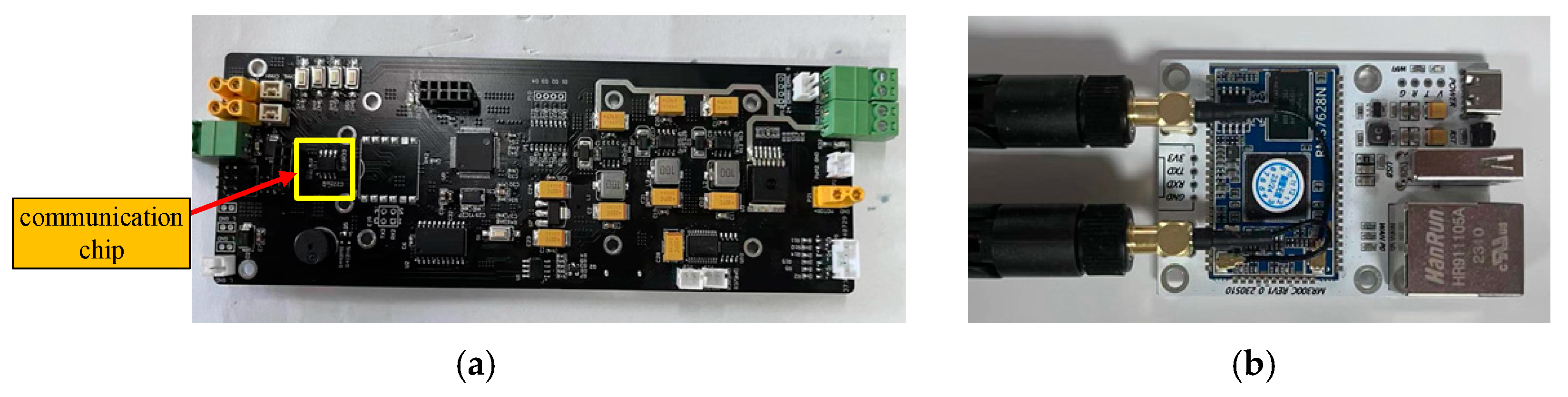
3.1. Robot Overall Structure Design
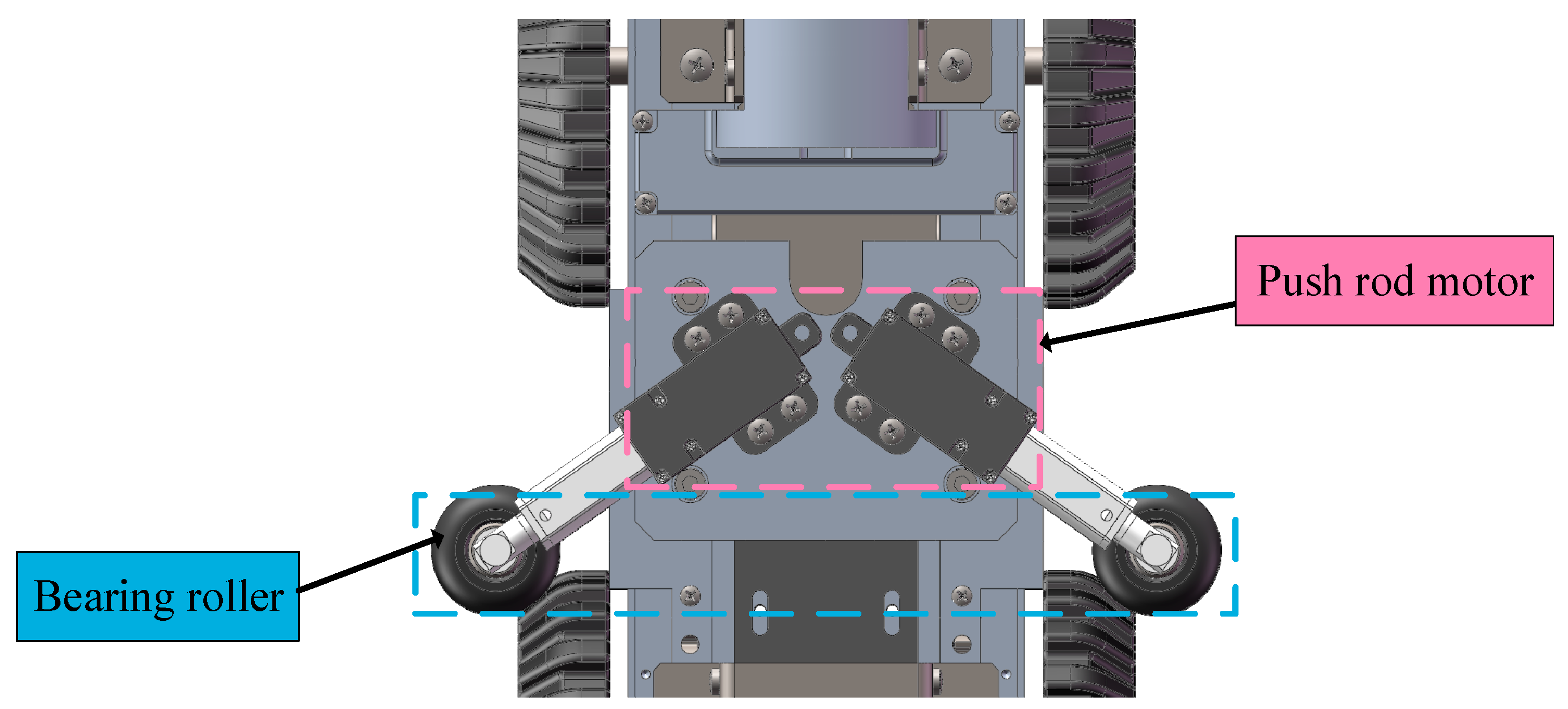
3.2. Robot Body and Bracing Module Design
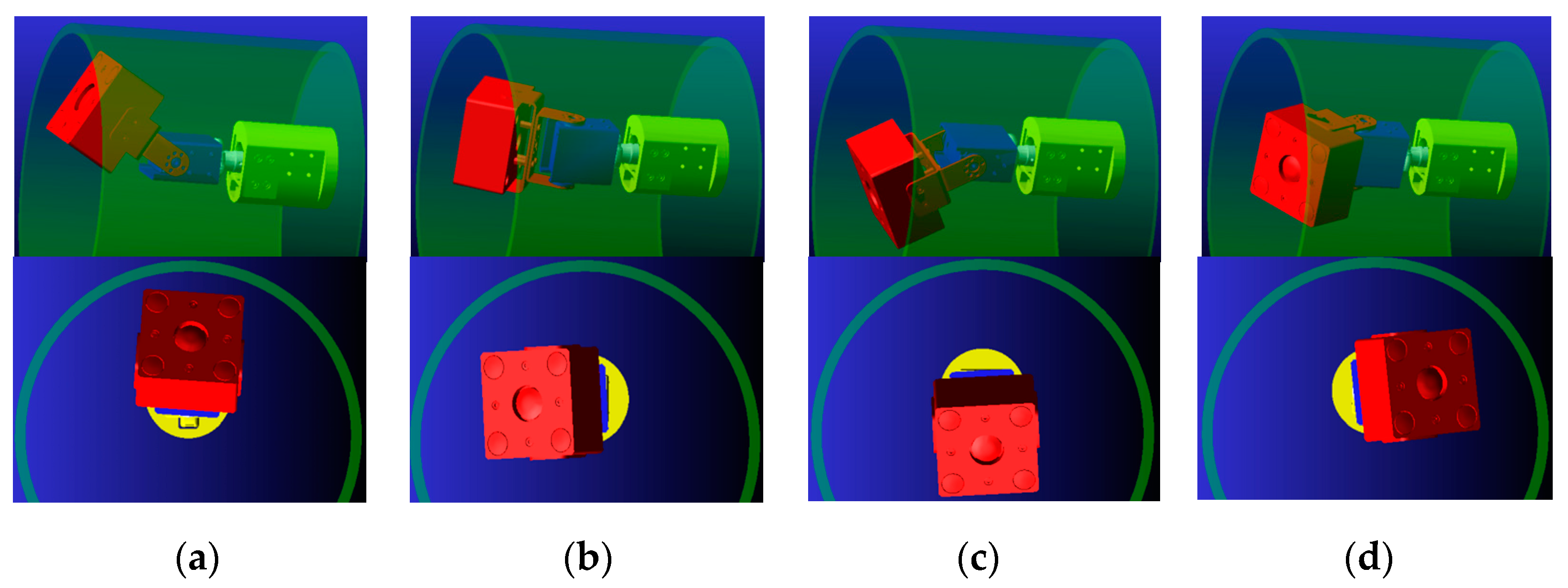
3.3. Robot Detection and Vacuuming Module Design
4. Robot Simulation Analysis
4.1. Simulation Analysis of Robot Body and Bracing Module
4.2. Simulation Analysis of Robot Detection and Dust Collection Module
5. Robot Experiment Verification
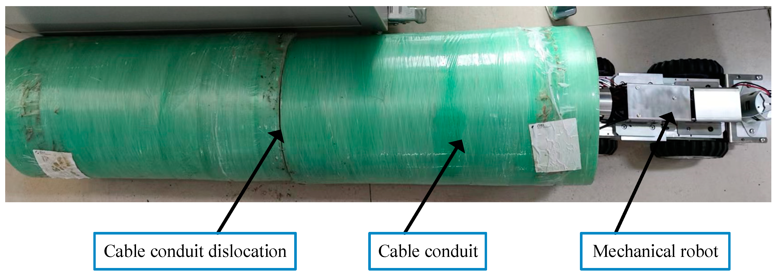
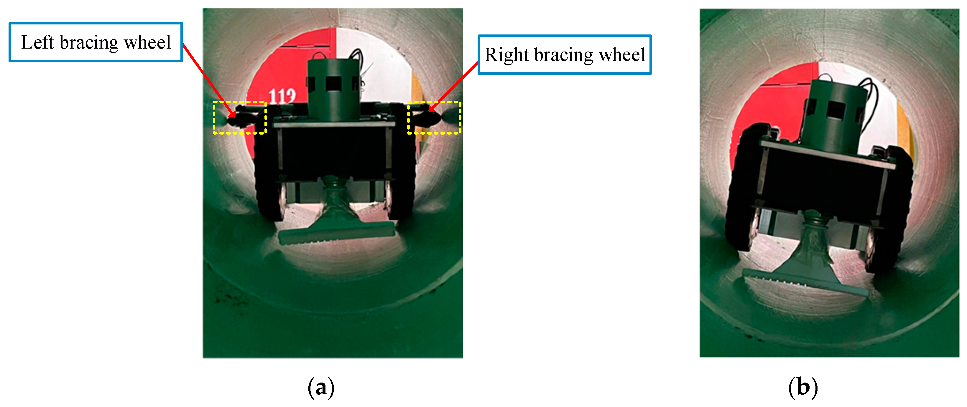
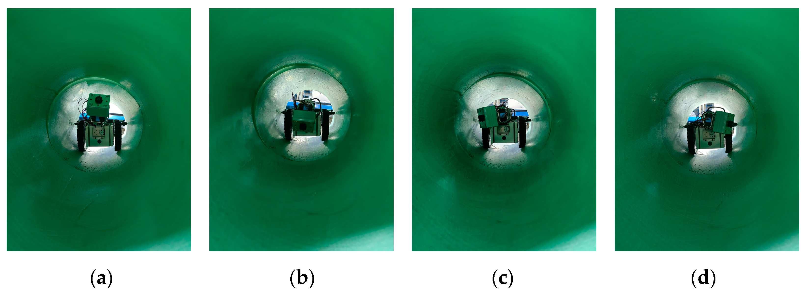
5.1. Experimental Verification of Robot Body and Bracing Module
5.2. Experimental Verification of Robot Detection and Vacuuming Module
6. Conclusions
Author Contributions
Funding
Data Availability Statement
Conflicts of Interest
References
- Rusu, C.; Tatar, M.O. Adapting Mechanisms for In-Conduit Inspection Robots: A Review. Appl. Sci. 2022, 12, 6191. [Google Scholar] [CrossRef]
- Verma, A.; Kaiwart, A.; Dubey, N.D.; Naseer, F.; Pradhan, S. A review on various types of in-conduit inspection robot. Mater. Today Proc. 2022, 50, 1425–1434. [Google Scholar] [CrossRef]
- Elankavi, R.S.; Dinakaran, D.; Jose, J. Developments in conduit inspection robot: A review. J. Mech. Contin. Math. Sci. 2020, 15, 238–248. [Google Scholar]
- Elankavi, R.S.; Dinakaran, D.; Chetty, R.K.; Ramya, M.M.; Samuel, D.H. A review on wheeled type in-conduit inspection robot. Int. J. Mech. Eng. Robot. Res. 2022, 11, 745–754. [Google Scholar]
- Thung-Od, K.; Kanjanawanishkul, K.; Maneewarn, T.; Sethaput, T.; Boonyaprapasorn, A. An In-Pipe Inspection Robot with Permanent Magnets and Omnidirectional Wheels: Design and Implementation. Appl. Sci. 2022, 12, 1226. [Google Scholar] [CrossRef]
- Cardona, M.; Cerrato, J.; García, E. Design and Simulation of a Mobile Robot for Conduit Inspection. In Proceedings of the 2022 IEEE Central America and Panama Student Conference (CONESCAPAN), San Salvador, El Salvador, 18–21 October 2022; pp. 1–6. [Google Scholar]
- Tang, S.; Chen, S.; Liu, Q.; Wang, B.; Guo, X. A Small Tracked Robot for Cable Tunnel Inspection. In Advances in Automation and Robotics; Lee, G., Ed.; Lecture Notes in Electrical Engineering; Springer: Berlin/Heidelberg, Germany, 2011; Volume 122, pp. 591–598. [Google Scholar]
- Wang, J.; Mo, Z.; Cai, Y.; Wang, S. Kinematic Analysis of a Wheeled-Leg Small Conduit Robot Turning in Curved Pipes. Electronics 2024, 13, 2170. [Google Scholar] [CrossRef]
- Li, M.; Wang, G.; Wang, J.; Zheng, Y.; Jiao, X. Development of an inchworm-like soft conduit robot for detection. Int. J. Mech. Sci. 2023, 253, 108392. [Google Scholar] [CrossRef]
- Liu, J.; Li, M.; Wang, Y.; Zhao, D.; Deng, R. Multi-gait snake robot for inspecting inner wall of a conduit. Biomim. Intell. Robot. 2024, 4, 100156. [Google Scholar]
- Fang, Y.; Wang, S.; Bi, Q.; Cui, D.; Yan, C. Design and Technical Development of Wall-Climbing Robots: A Review. J. Bionic Eng. 2022, 19, 877–901. [Google Scholar] [CrossRef]
- Wang, Z.; Wang, Y.; Zhang, B. Development and Experiment of Clamp Type Submarine Cable Inspection Robot. Machines 2023, 11, 627. [Google Scholar] [CrossRef]
- Li, J.; Huang, F.; Tu, C.; Tian, M.; Wang, X. Elastic Obstacle-Surmounting Conduit-Climbing Robot with Composite Wheels. Machines 2022, 10, 874. [Google Scholar] [CrossRef]
- Zheng, Z.; Zhang, W.; Fu, X.; Hazken, S.; Hu, X.; Chen, H.; Luo, J.; Ding, N. CCRobot-IV: An Obstacle-Free Split-Type Quad-Ducted Propeller-Driven Bridge Stay Cable-Climbing Robot. IEEE Robot. Autom. Lett. 2022, 7, 11751–11758. [Google Scholar] [CrossRef]
- Tang, Z.; Li, Z.; Ma, S.; Chen, Y.; Yang, Y. Structure Design of Adaptive Conduit Detection Robot. In Proceedings of the 2021 7th International Conference on Control, Automation and Robotics (ICCAR), Singapore, 23–26 April 2021; pp. 136–140. [Google Scholar]
- Yan, H.; Zhao, P.; Xiao, C.; Zhang, D.; Jiao, S.; Pan, H.; Wu, X. Design and Kinematic Characteristic Analysis of a Spiral Robot for Oil and Gas Conduit Inspections. Actuators 2023, 12, 240. [Google Scholar] [CrossRef]
- Zhang, L.; Wang, X. Stable motion analysis and verification of a radial adjustable conduit robot. In Proceedings of the 2016 IEEE International Conference on Robotics and Biomimetics (ROBIO), Qingdao, China, 3–7 December 2016; pp. 1023–1028. [Google Scholar]
- Zhang, Y.; Chen, H.; Wang, L.; Fu, Z.; Wang, S. Design of a Novel Modular Serial Conduit Inspection Robot. In Proceedings of the 2023 IEEE International Conference on Mechatronics and Automation (ICMA), Harbin, China, 6–9 August 2023; pp. 1847–1852. [Google Scholar]
- Chen, Y.; Liu, S.; Hao, L.; Chi, F.; Xu, H.; Li, C. Analysis of Kinematic Characteristics of Cable Ducting Robot. In Proceedings of the 2022 4th International Conference on Power and Energy Technology (ICPET), Beijing, China, 28–31 July 2022; pp. 1192–1198. [Google Scholar]
- Liu, F.; Sun, W. Analysis and Simulation of the Passability of Adaptive Conduit Grinding Robot. Mach. Tool Hydraul. 2021, 49, 15–21. [Google Scholar]


| Robot Mass m/kg | Conduit Diameter Range D/mm | Number of Driving Wheels | Detection Angle α0/(°) | Inclination Angle θ/(°) | Vacuuming Negative Pressure p/kPa |
|---|---|---|---|---|---|
| ≤12 | 225–275 | 4 | 360 | ≤8 | ≥3 |
| Abbreviation | Direction of Center of Mass | Bracing Mechanism Presence | Operating Speed v/(m/s) |
|---|---|---|---|
| Case 1 | X | Without bracing | 0.1 |
| Case 2 | X | With bracing | |
| Case 3 | Y | Without bracing | |
| Case 4 | Y | With bracing | |
| Case 5 | X | Without bracing | 0.2 |
| Case 6 | X | With bracing | |
| Case 7 | Y | Without bracing | |
| Case 8 | Y | With bracing | |
| Case 9 | X | Without bracing | 0.3 |
| Case 10 | X | With bracing | |
| Case 11 | Y | Without bracing | |
| Case 12 | Y | With bracing |
| Abbreviation | Types of Forces | Operating Speed v/(m/s) |
|---|---|---|
| Case 13 | Contact force | 0.1 |
| Case 14 | Rolling friction force | |
| Case 15 | Contact force | 0.2 |
| Case 16 | Rolling friction force | |
| Case 17 | Contact force | 0.3 |
| Case 18 | Rolling friction force |
| Key Parameter | Numerical Value |
|---|---|
| Robot mass m/kg | 10 |
| The traveling speed of the robot v/(km/h) | 0.5–15 |
| Driving motor power P/W | 14 |
| Adaptable conduit diameter D/mm | 225–275 |
| Battery endurance of the robot T/h | 4 |
Disclaimer/Publisher’s Note: The statements, opinions and data contained in all publications are solely those of the individual author(s) and contributor(s) and not of MDPI and/or the editor(s). MDPI and/or the editor(s) disclaim responsibility for any injury to people or property resulting from any ideas, methods, instructions or products referred to in the content. |
© 2024 by the authors. Licensee MDPI, Basel, Switzerland. This article is an open access article distributed under the terms and conditions of the Creative Commons Attribution (CC BY) license (https://creativecommons.org/licenses/by/4.0/).
Share and Cite
You, Y.; Zheng, Y.; Huang, K.; He, Y.; Huang, Z.; Zhan, L. Development of a Small-Sized Urban Cable Conduit Inspection Robot. Actuators 2024, 13, 349. https://doi.org/10.3390/act13090349
You Y, Zheng Y, Huang K, He Y, Huang Z, Zhan L. Development of a Small-Sized Urban Cable Conduit Inspection Robot. Actuators. 2024; 13(9):349. https://doi.org/10.3390/act13090349
Chicago/Turabian StyleYou, Yiqiang, Yichen Zheng, Kangle Huang, Yuling He, Zhiqing Huang, and Lulin Zhan. 2024. "Development of a Small-Sized Urban Cable Conduit Inspection Robot" Actuators 13, no. 9: 349. https://doi.org/10.3390/act13090349