Article

A Novel Design of Soft Corrugated Actuator for Creating Precise Head and Neck Positioning System

1
The University of Texas at Arlington Research Institute, 7300 Jack Newell Blvd S, Fort Worth, TX 76118, USA
2
Radiation Oncology, The University of Texas Southwestern Medical Center, 5323 Harry Hines Blvd, Dallas, TX 75390, USA
*
Author to whom correspondence should be addressed.
Actuators 2024, 13(9), 351; https://doi.org/10.3390/act13090351
Submission received: 21 August 2024 / Revised: 5 September 2024 / Accepted: 9 September 2024 / Published: 11 September 2024
(This article belongs to the Special Issue Actuators and Robots for Biomedical Applications)

Abstract

:
Soft robots are increasingly gaining popularity as a preferred choice for designing medical devices due to their inherently compliant and adaptable nature. As research continues to advance in this field, soft robots are poised to revolutionize healthcare by providing safer, more patient-centric solutions. This paper presents the design of a novel soft corrugated actuator to create a system for positioning the head during head and neck cancer radiation therapy. Simulation and experimental data show that the presented actuator design can achieve linear expansion with respect to pressure in both free and under loading conditions. A machine learning model of the single actuator is created using experimental data (pressure, expansion, and weight) to predict the required pressure. The single actuator model’s validity is confirmed by using four actuators to achieve head flexion at a specific angle, illustrating its potential for implementation in a multi-actuator system. The preliminary design of the multi-actuator head and neck positioning system demonstrates its capability to achieve four degrees of freedom.

1. Introduction

Soft pneumatic actuators are a key component in soft robotics, offering unique capabilities due to their inherent compliance and safety. Soft pneumatic actuators have been employed in a wide range of applications. Some notable applications include wearable assistive devices [1,2,3], minimally invasive surgeries [4], gripping and manipulation [5], locomotion [5], etc. Recently, a novel soft robot with McKibben muscles has been proposed for different applications, such as a peristaltic transporting device [6] and a human muscle configuration-inspired wearable suit [7]. Many of these applications require precise control of soft robotic actuators; however, achieving high precision is challenging due to the inherent non-linear behavior of soft actuators. Recent work on modular corrugated pneumatic actuators shows that actuator design can potentially reduce non-linear behavior [8]. The main objective of this work is to investigate the development and modeling of the corrugated actuator to create a robotic manipulation system for precise H&N (Head and Neck) positioning during the treatment of H&N cancer.
H&N cancers are a significant health concern, with approximately 65,000 new cases expected to be diagnosed in the U.S. in 2024 [9]. These cancers account for about 4% of all cancer cases in the USA [10]. Despite advancements in precise radiation techniques, such as intensity-modulated radiation therapy and stereotactic body radiation therapy, maintaining accurate head positioning during treatment remains essential. Accurate positioning maximizes treatment effectiveness while minimizing the risk of damage to surrounding healthy tissues [11,12]. Currently, an immobilization mask is used to position the head correctly during radiation therapy [13]. However, these masks can cause significant discomfort, particularly during prolonged treatments, leading to increased movement and posing challenges for very young or elderly patients. Additionally, about 50% of patients, regardless of pre-existing mental health conditions, experience significant anxiety and distress from the immobilization mask [13]. While frameless and maskless radiosurgery systems have been developed to treat intracranial tumors, these systems often lack an automatic feedback loop for adjustments, requiring time-consuming manual intervention [14,15]. Additionally, some existing maskless head positioning systems are incompatible with the radiation environment, such as a 6 degrees of freedom (DoF) head positioning system that uses motors beneath the head, which can interfere with the radiation beams and compromise treatment accuracy [16]. A head positioning system based on soft pneumatic actuators has been studied by Ogunmolu et al. [17]. This system utilized three soft actuators to enable 3 DoF head movements. The actuators in the setup were modeled as a parallel mechanism for the real-time motion correction of the patient’s head deviation [18]. The study laid a foundational framework, emphasizing the potential of soft actuators in developing a head positioning system. However, the key limitations of this setup are the limited DoF and the non-linear expansion behavior of the actuators, which complicates accurate modeling and control.
This work explores the use of a corrugated soft actuator as an application of the H&N positioning system, which can provide maskless cancer treatment and significantly alleviate patient discomfort, anxiety, and distress caused by wearing a mask. This paper outlines the design, characterization, and modeling of corrugated actuators and explores their potential for developing H&N positioning systems. The characterization will detail the expansion characteristics of the corrugated actuator validated through simulation and experimental studies. The machine learning (ML) model of the actuator is used to predict the pressure required for target expansion. The preliminary design of a multi-actuator head positioning system and its capability to achieve multiple DoF of head movement will be demonstrated. This manuscript has two main contributions:
  • A corrugated actuator design that can produce linear displacement in response to applied pressure, which can aid in the implementation of accurate closed-loop control.
  • The development of a multi-actuator system that provides 4 DoF for head positioning during cancer treatment.

2. Materials and Methods
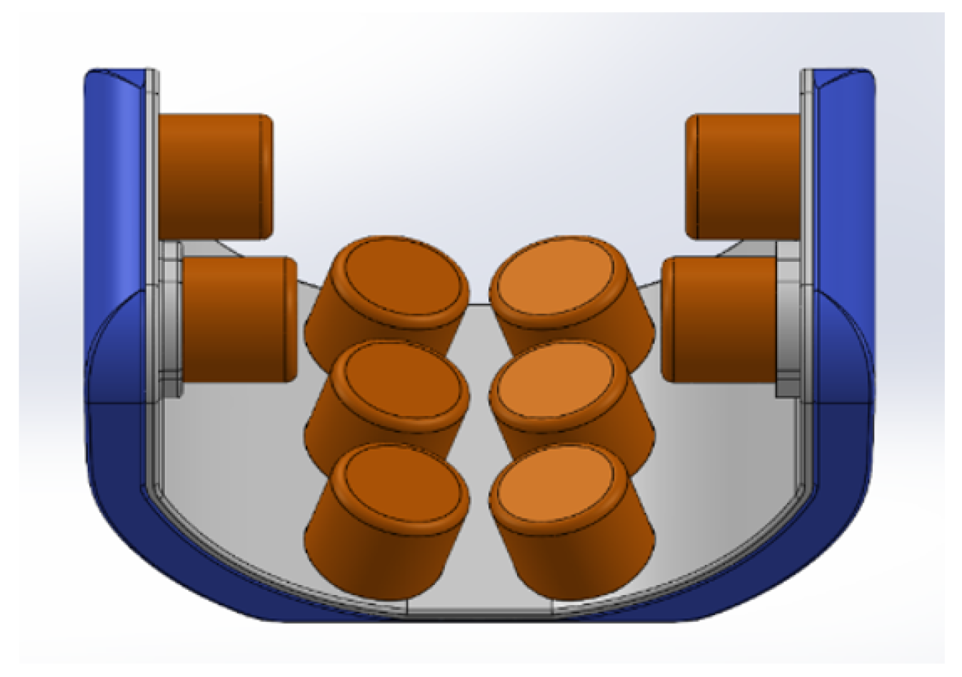
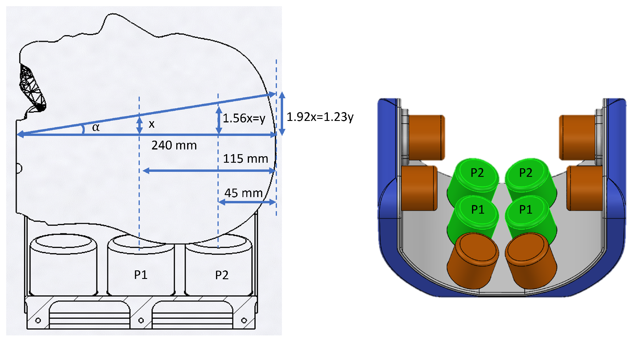
A preliminary head positioning system is designed by considering the limitations of previous systems [17,18]. In this study, the head needs to rotate either ± 5 degrees or translate a maximum of 20 mm, with a precision of 0.5 degrees and 1 mm in rotation and translation, respectively. Additionally, the system should have at least 4 DoF (three rotations and one translation) to move the head to a desired position. To address these needs, starting from a single corrugated actuator design, its critical dimensions are optimized. By using the optimized actuator geometry, the number and configuration of the actuators are further studied to create a multi-actuator head positioning system.

2.1. System Design

A preliminary head positioning system (Figure 1), consisting of 10 actuators (in orange) integrated within a frame (represented in gray and blue), is designed for the purpose of moving and stabilizing a patient’s head during cancer treatment. Each actuator can be pressurized individually. The system is strategically configured, with six actuators placed at the base to facilitate head flexion/extension and translation movements, while the remaining four actuators—two on each side—enable head rotation and lateral flexion as well as head stabilization. The gap between the side actuators is larger than that between the bottom actuators to accommodate the ears and prevent any discomfort due to pressure during therapy. This configuration is designed to achieve precise manipulation of the patient’s head in four DoF, ensuring accurate and stable positioning throughout the treatment process.

2.2. Single Actuator Design and Simulation Studies

A single actuator is designed using cylindrical geometry with a triangular corrugation pattern, as shown in Figure 2. The corrugation is located on the bottom side of the actuator, with the air inlet for inflation/deflation also situated on the same side. Simulation studies are performed in two stages, utilizing ANSYS® transient structural analysis using polyurethane (PMC®-724 Smooth-On) material properties. During the first stage, critical actuator dimensions such as inner diameter ( d i ), wall thickness ( t w ), and corrugation thickness ( t c ) are studied and optimized to achieve linear expansion behavior. Figure 2 displays the actuator’s 3D and cross-sectional views, highlighting the critical dimensions. The optimal values of these dimensions are listed in Table 1.
In the second stage, simulation studies are performed to investigate the optimized actuator’s expansion behavior under both free-loading and applied loading conditions. The actuator’s expansion behavior is validated using the same boundary conditions as depicted in the experimental setup shown in Figure 3. The inner diameter section ( d i ) on the corrugated side (Figure 2) is fixed. Frictional contacts are added between the rods and the top plate, and between the top side of the actuator and the bottom side of the top plate, with a friction coefficient of 0.1. The bottom plate is secured with fixed supports. Hydrostatic pressure is applied to all internal surfaces of the actuator. Weights ranging from 0 to 2000 g, in 500 g increments, are applied to the top side of the actuator. The actuator is pressurized from 0 to 55 kPa, and vertical expansion on the top side is monitored. The default convergence criteria in ANSYS®—displacement of 0.0636 mm and force of 0.00893 N—are used. A mesh independence study is conducted with element counts of 1 time, 5 times, and 50 times to confirm that the displacement results are independent of mesh density. The simulation results are compared with experimental data to validate the single actuator simulations.

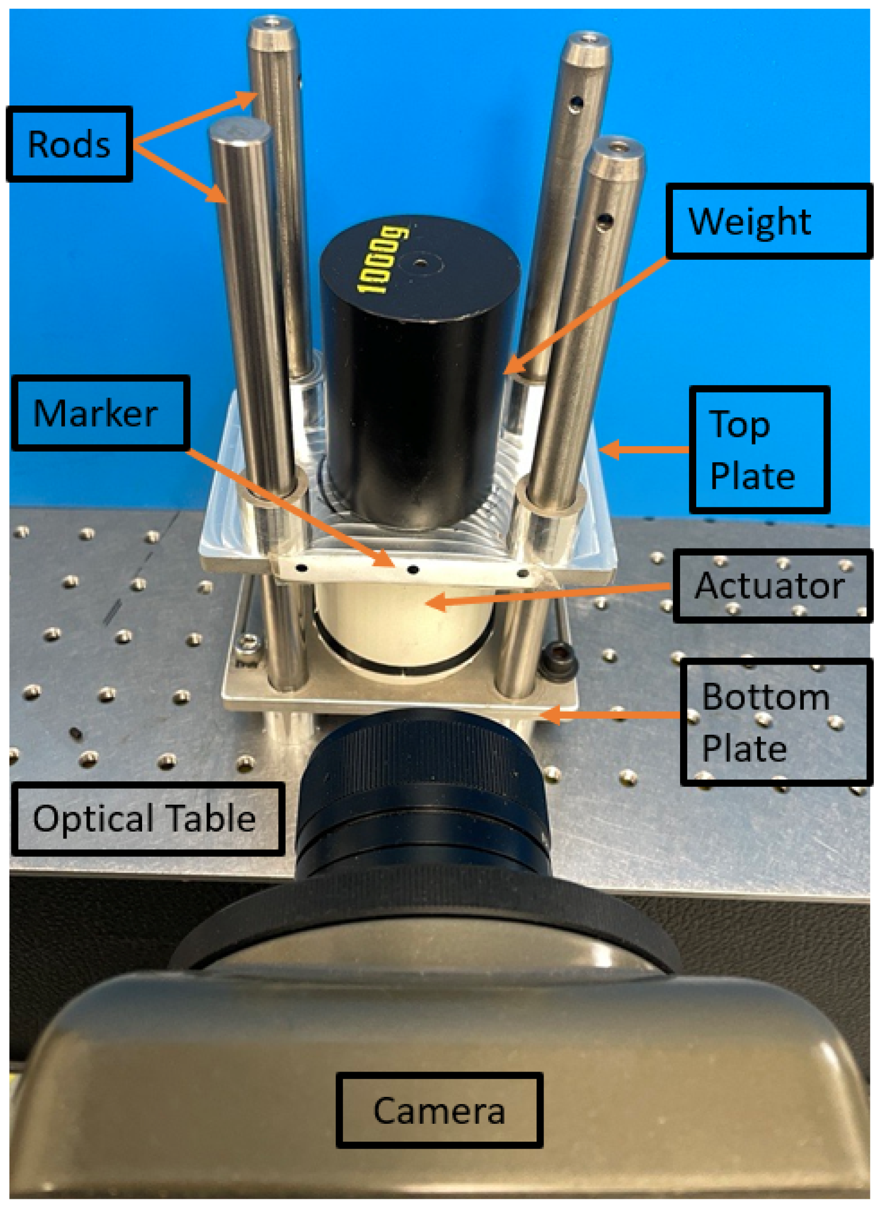
2.3. Single Actuator Fabrication and Experimental Setup

Actuators are fabricated with polyurethane (PMC®-724 Smooth-On) material using a liquid compression molding technique similar to previously published work [8]. PMC®-724 material has a tensile strength of 4.13 MPa, an elongation at break of more than 700%, and a Shore A hardness of 40 [19]. The experimental setup (Figure 3) for the single actuator includes steel rods, the corrugated actuator, a top, and a bottom plate. The bottom plate is secured to the optical table, and the actuator is attached to the bottom plate using screws and nuts. When the actuator is pressurized, it exerts force on the top plate, causing the plate to move in the vertical direction. This setup is constructed to collect displacement data under varying loads (weights) ranging from 0 to 2000 g in 500 g increments, while the actuator is pressurized up to 55 kPa (8 psi). A Phantom high-speed camera is used to capture displacement at corresponding pressure values using markers, as shown in Figure 3. Displacement data are obtained using the open-source digital image correlation MATLAB code, Ncorr [20]. This code uses an initial image of the actuator (when the pressure is zero) as a reference image to compute the displacement values throughout the experiment. These experimental data are used to validate the simulation results in Section 4.1.

2.4. Single Actuator Modeling

The design of a single actuator is optimized to achieve linear expansion with respect to pressure under both free and loaded conditions. When weight, pressure, and expansion are considered simultaneously, the model becomes more complex. This study aims to develop a predictive ML model to forecast actuator pressure using weight and desired displacement as input features. Building a customized predictive model involves multiple stages. The following steps outline our approach:
  • Data Collection;
  • Exploratory Data Analysis and Data Pre-Processing;
  • ML Model for Single Actuator.

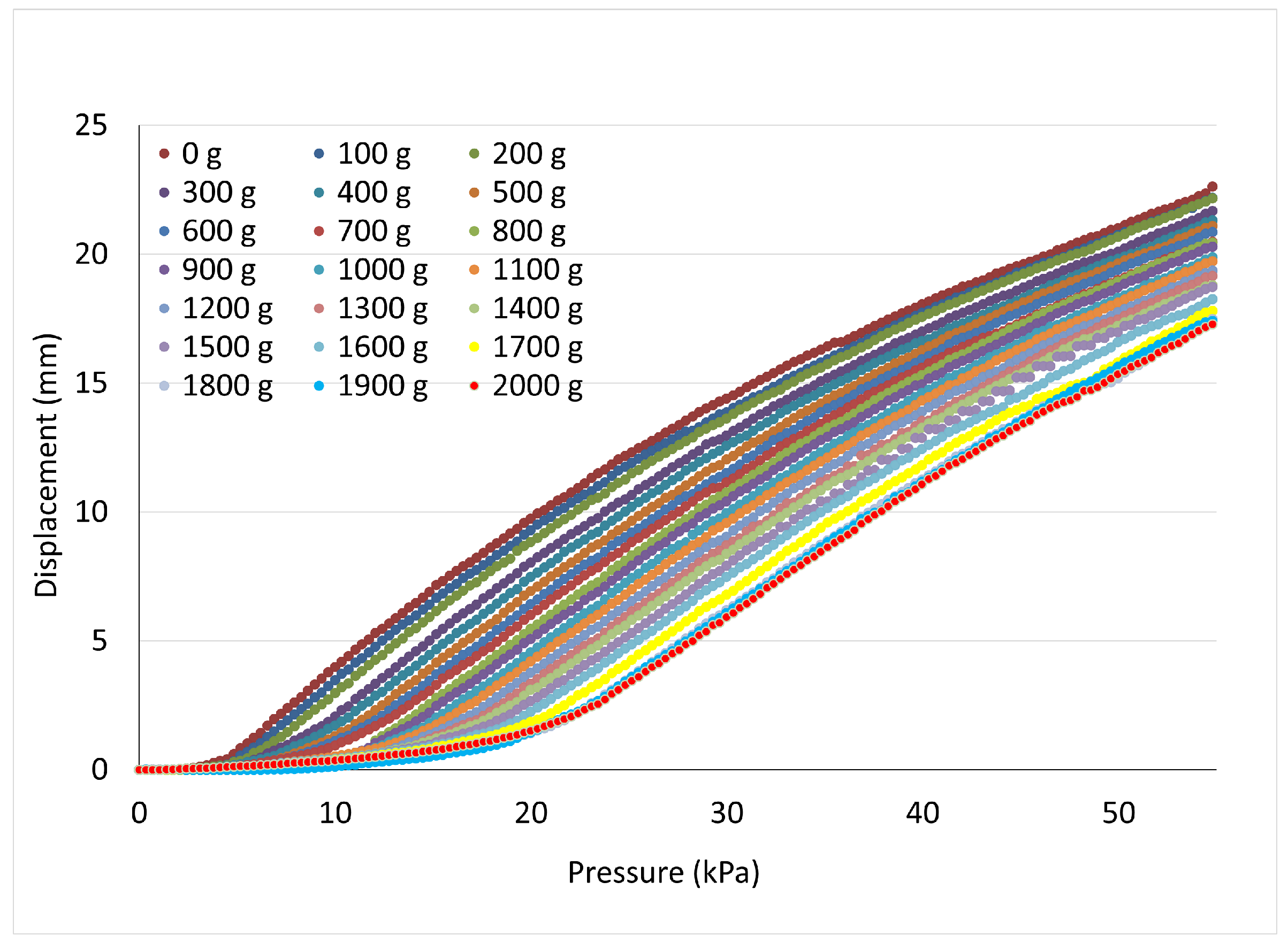
2.4.1. Data Collection

To construct an effective ML model, the quality and quantity of data are paramount. Our experimental setup is designed as shown in Figure 3. The displacement data are collected using a camera (Phantom high-speed camera) for pressure ranging from 0 to 55 kPa and weight ranging from 0 to 2000 g in step sizes of 100 g (a smaller weight size is chosen to satisfy ML algorithm data quantity needs). Advanced image correlation techniques using Matlab’s Ncorr program are used to capture and analyze displacement variations corresponding to each weight and pressure combination, as shown in Figure 4. The total number of dataset samples collected experimentally is 3381. The dataset is divided, allocating 75% for training the model and the remaining 25% for evaluating its performance.

2.4.2. Exploratory Data Analysis and Data Pre-Processing

During this phase, an in-depth exploration and understanding of the dataset are obtained to facilitate further processing and model implementation. Key metrics such as mean and standard deviation (Std Dev) are systematically computed to facilitate a better understanding of the characteristics of the dataset.
  • Statistical Overview: One fundamental metric examined is the Std Dev, which is used to measure the skewness of the dataset. This could affect the modeling of distance-based methods, such as K-Nearest Neighbor (KNN), discussed in Section 2.4.3. Notably, the weight parameter exhibits a relatively high Std Dev (605.619 g), indicating substantial dispersion among the collected data points. To address this, statistical log transformation is applied to the weight feature, which effectively reduced its Std Dev (1.626 g) [21].
    W * = l o g ( W + 1 )
    Here, W * denotes transformed weight, log denotes natural logarithm function, W denotes original weight values, and constant value 1 handles 0 g weight. Equation (1) shows statistical log transformation.
  • Feature Analysis: The selection of the regression model and appropriate feature transformation is determined based on the relationship between each feature and the target variable. In our case, the two features (weight and displacement) and the target variable (pressure) are analyzed for their correlations to select the most suitable model.
    This analysis provides the basis for applying strategic polynomial feature transformation [22], which allows us to derive the interaction effects of weight and displacement features on pressure, leading to a better fit for the regression model.
    The optimal degree of the polynomial features is chosen using a grid search with cross-validation (GridSearchCV) [23] and regression modeling [24], with respect to weight and displacement, to find the degree with the least Mean Squared Error (MSE) in pressure prediction. Regression modeling is further substantiated in Section 2.4.3.
    From Figure 5, we can infer that polynomial degree 6 is the optimal degree for our model with the least MSE.
  • Data Augmentation: To handle insufficient sample size that could lead to overfitting, in which the model performs well on the training set but poorly on unseen data, we employ the following techniques:
    (a)
    Bootstrapping: We augment the dataset to generate an additional 1619 records by iteratively selecting random samples from the original dataset and adding these samples back as new data, which expands the overall dataset size to the desired length [25].
    (b)
    Gaussian Noise: During model validation with unseen data, we observe instances where the model predicted identical pressure values for static weights that only differed in displacement. This behavior indicated overfitting. Gaussian noise [26] is introduced, thereby enabling model generalization, while preserving the statistical properties of the original dataset.
    By applying Bootstrapping and introducing Gaussian noise, we are able to improve data quality and quantity, which will help produce effective actuator pressure predictions.

2.4.3. ML Model for Single Actuator

This section further explores the mathematical model underlying polynomial regression and the implementation of another robust ML algorithm, K-Nearest Neighbors (KNN). It is clear from the polynomial feature transformation stage that a sixth degree polynomial is the most suitable to fit the data (shown in Figure 5). By performing this step, the dataset is transformed from 2 features (weight and displacement) to a 27-feature dataset by capturing the interactions between weight and displacement up to degree 6. The polynomial equation of the model is given by
P = i = 0 6 j = 0 6 i β i j D i W * j + ϵ
where P represents the predicted pressure; D displacement and W * transformed weight are the feature variables; β denotes the coefficients of the polynomial terms, with i and j to be the exponents of D and W * , respectively, with the constraint i + j 6 , ϵ denoting the error term.
To select the most relevant features, we employed Lasso regularization [27], a technique known for its ability to perform both feature selection and regularization by driving less important feature coefficients to zero. Through this process, we identified four key features—D, the interaction term D W * , the quadratic term D W * 2 , and the higher-order term W * 6 —to be the most relevant features on which the linear model performed the best.
To enhance the predictive performance and sensitivity of the model concerning variations in weight and displacement, we implement the KNN algorithm [28] in conjunction with K-Fold Cross-Validation. In our implementation, we employ the Euclidean Distance to compute the proximity of neighbors to the test data point, and the average of the results is the predicted pressure. Similar to the method used for selecting the optimal polynomial degree in Section 2.4.2 via GridSearchCV, we vary the number of neighbors (K) and identified that K = 3 has the lowest Root Mean Squared Error. The distance calculation is given by
d ( W 1 * , D 1 ) , ( W 2 * , D 2 ) = ( W 1 * W 2 * ) 2 + ( D 1 D 2 ) 2
where W 1 * , D 1 represent the transformed weight and displacement of a specific training data point, and W 2 * , D 2 represent the transformed weight and displacement of the new test data point.
Throughout the modeling stages, we addressed overfitting concerns using several key strategies. First, we applied log transformation during preprocessing to standardize feature scales, ensuring consistent treatment across features. To further address the overfitting, we incorporated Gaussian noise and Bootstrapping, which mitigated sensitivity to specific input variables’ (displacement, weight) combinations. We utilized GridSearchCV to optimize the polynomial degree during feature transformation and applied K-Fold Cross-Validation to determine the optimal number of neighbors for the KNN algorithm on both the training and validation sets. Lasso regularization is also used to select the most significant features and thereby dampens the effect of overfitting.

2.4.4. Model Evaluation

Regression models’ performance is evaluated with the MSE and Coefficient of Determination (R2 Score) using the test data. The MSE quantifies the deviation between predicted and actual pressure values on the test data, and the R2 Score is a measure of the overall accuracy of the pressure prediction model. Table 2 depicts the evaluation results from applying polynomial regression and KNN-CV ML algorithms.
The results indicate that incorporating the KNN-CV algorithm enhanced the model’s accuracy by approximately 8.6% and the model is able to account for 99.14% of variability in actuator pressure. This is used to validate the single actuator model results in Section 4.2.

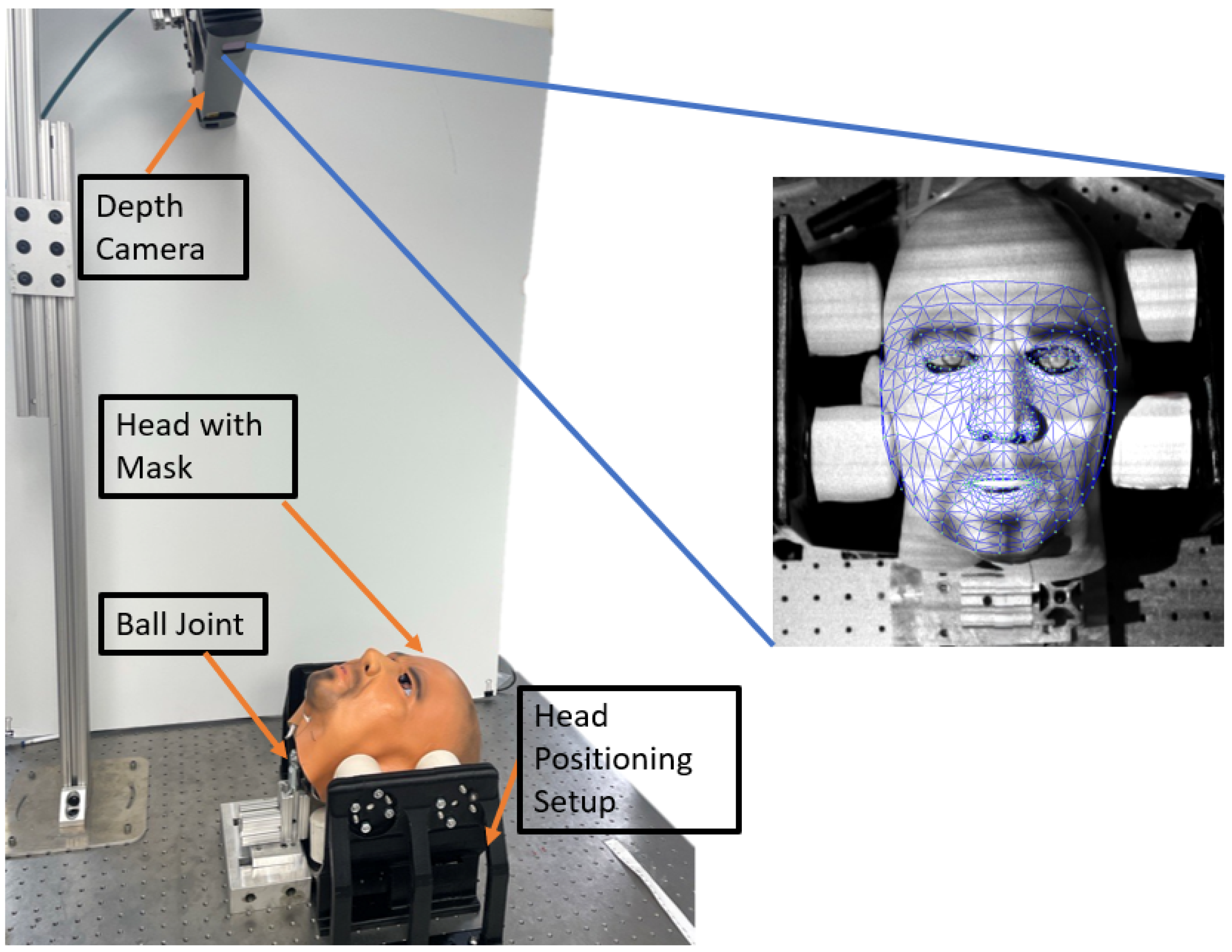
3. Application: Multi-Actuator H&N Positioning System

After the completion of single actuator design and modeling, the work is extended to use multiple single actuators to model and test an H&N positioning system.

3.1. System Fabrication and Experimental Setup

The head positioning system consists of a multi-actuator head positioning setup (Figure 1) and a control box. The prototype of the head positioning system is constructed by assembling ten corrugated actuators onto a frame (3D-printed PLA), which is then mounted on an optical table, as shown in Figure 6. All of the actuators can be pressurized separately. The internal pressure of each actuator can be monitored and controlled using pressure sensors and valves, respectively. The head used in this setup is a standard model for headgear and helmet testing. It is a high bio-fidelity human head that replicates the center of gravity and weight of an actual human head, enabling us to test the capability of the system. The head is mounted on a ball joint, which is secured to the optical table. The head is covered with a mask to enhance the accuracy of the face-tracking algorithm used by the Photoneo Motion-Cam 3D M. The head translation and rotation data are collected using the camera. The code written in Python utilizes the MediaPipe library to detect face landmarks (shown as a camera view in Figure 6), providing the coordinates (x, y, z) of each landmark in each frame. Each frame contains 478 landmarks. To filter the data over time, a median filter with a kernel size of 5 is applied. Subsequently, we perform Principal Component Analysis (PCA) using Singular Value Decomposition (SVD) on the centered data. PCA helps us determine the three primary axes of the object, which correspond to the directions in which the head varies most in the 3D space. By applying SVD, we decompose the centered data into their principal components, where each principal component corresponds to one of these primary axes. The resulting principal components form the columns of the rotation matrix, which provides a mathematical representation of the head’s orientation with respect to the camera.

3.2. Multi-Actuator System Model

In the case of a multi-actuator head positioning model, geometric modeling is employed to determine the precise expansion of each actuator necessary to achieve a desired head rotation angle. This involves calculating how much each actuator must expand to produce the correct movement of the head. Once the required expansions are determined, the single-actuator model is applied to each actuator individually to calculate the input pressure needed to achieve the specified expansion.
To verify this approach, the head flexion angle is considered. Head flexion can be generated using the four actuators at the base of the system (shown in green). As in Figure 7, the side view of the setup shows that the head is touching the last four actuators at the base. The geometrical modeling is used to calculate the expansion of these four actuators needed to achieve the target flexion angle ( α ). Then, the single-actuator model from Section 2.4 is used to calculate the input pressure required for each actuator. In this case, it is assumed that the weight of the head is distributed equally on the actuators in contact. The set of two actuators are at the same distance from the joint, as shown in Figure 7. Therefore, two pressures P 1 and P 2 are predicted using the model to inflate all of the four actuators to achieve the target head flexion.

4. Results

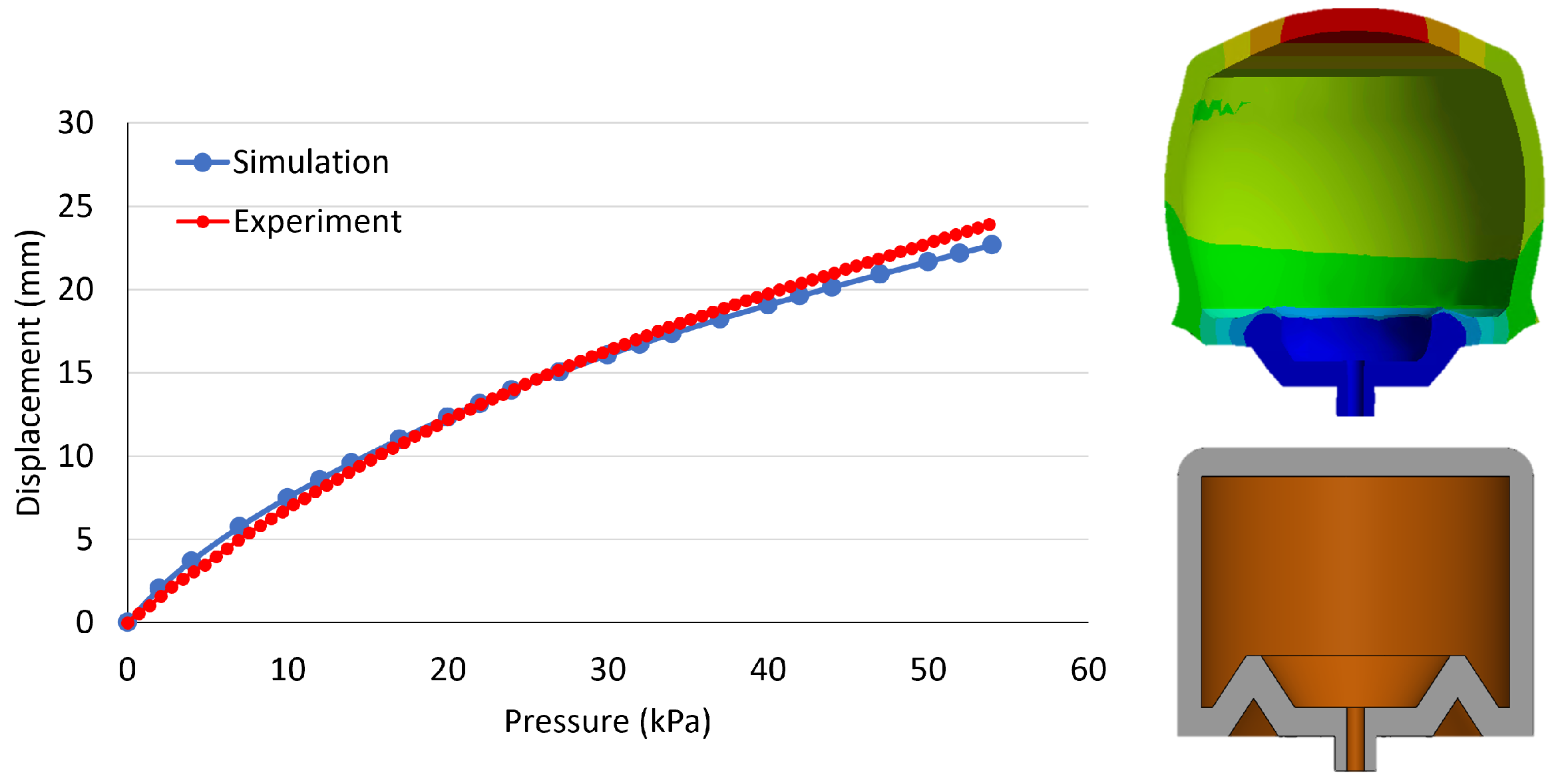
4.1. Single Actuator Simulation Validation

The simulation results of a single actuator’s expansion behavior (Section 2.2) have been validated through experimental testing, both in free conditions and under applied loads. The experimental setup is shown in Figure 3. Mesh independence is checked using 5 times and 50 times more elements for 0, 500, 1000, 1500, 2000 g weights. The maximum expansion difference between a different element number is 0.2 mm, indicating that the expansion results do not depend on the number of elements. These experiments confirm the accuracy of the simulations by demonstrating that the actuator’s behavior under both scenarios aligns with the predicted outcomes. Figure 8 shows the actuator’s free expansion behavior for the experiment and the simulation cases. This figure also shows the cross-section view of the actuator in normal and pressurized states during simulation.
Weights of 0, 500, 1000, 1500, and 2000 g are chosen to validate simulation data through experimental data. Table 3 presents the displacement values obtained experimentally and through simulation when the actuator is inflated to 55 kPa.
The maximum expansion deviation between the simulation and experimental results is 0.61 mm. With these validations under both free and loaded conditions, the optimized actuator design can be employed to develop a multi-actuator head positioning system.

4.2. Single Actuator Model Validation

The same experimental setup (Figure 3) is utilized to validate the single actuator ML model. The KNN with cross-validation model was employed due to its superior accuracy in predicting pressure. Eight random pairs (weight and displacement) of input data for the ML model are chosen to predict the pressure, as shown in Table 4. Then, predicted pressure is applied to the single actuator, and the expansion of the actuator is measured. Finally, input displacement and the measured displacement values are compared to compute the displacement deviation.
As indicated by the data presented in Table 4, applying the predicted pressure to the actuator for specified weight and target head displacement resulted in an achieved displacement that is consistently close to the desired value, with a maximum deviation of 1 mm, thus highlighting the high prediction accuracy achieved by our KNN-CV ML model.

4.3. Multi-Actuator System Model Validation

The multi-actuator system model is validated for head flexion movement. Four actuators shown in Figure 7 in a green color are used for head flexion. Four target flexion angles (2°, 4°, 6°, 8°) are selected for the model validation. The weight of the head including the joint is measured as 6000 g. The head is placed at the center of four actuators so that the head weight is equally distributed over the actuators, where each actuator experiences 1500 g. Thus, we assume that the set of two actuators need the same pressure, as they are in line and are at the same distance from the joint. Therefore, two pressures P 1 and P 2 need to be predicted to inflate four actuators to achieve the target flexion angles, as shown in Figure 7.
Multi-actuator model validation is shown in Table 5. The maximum deviation between the target and measured angle is 0.5°. Thus, geometrical features of the system with the combination of the single actuator ML model can be used for multi-actuator modeling.

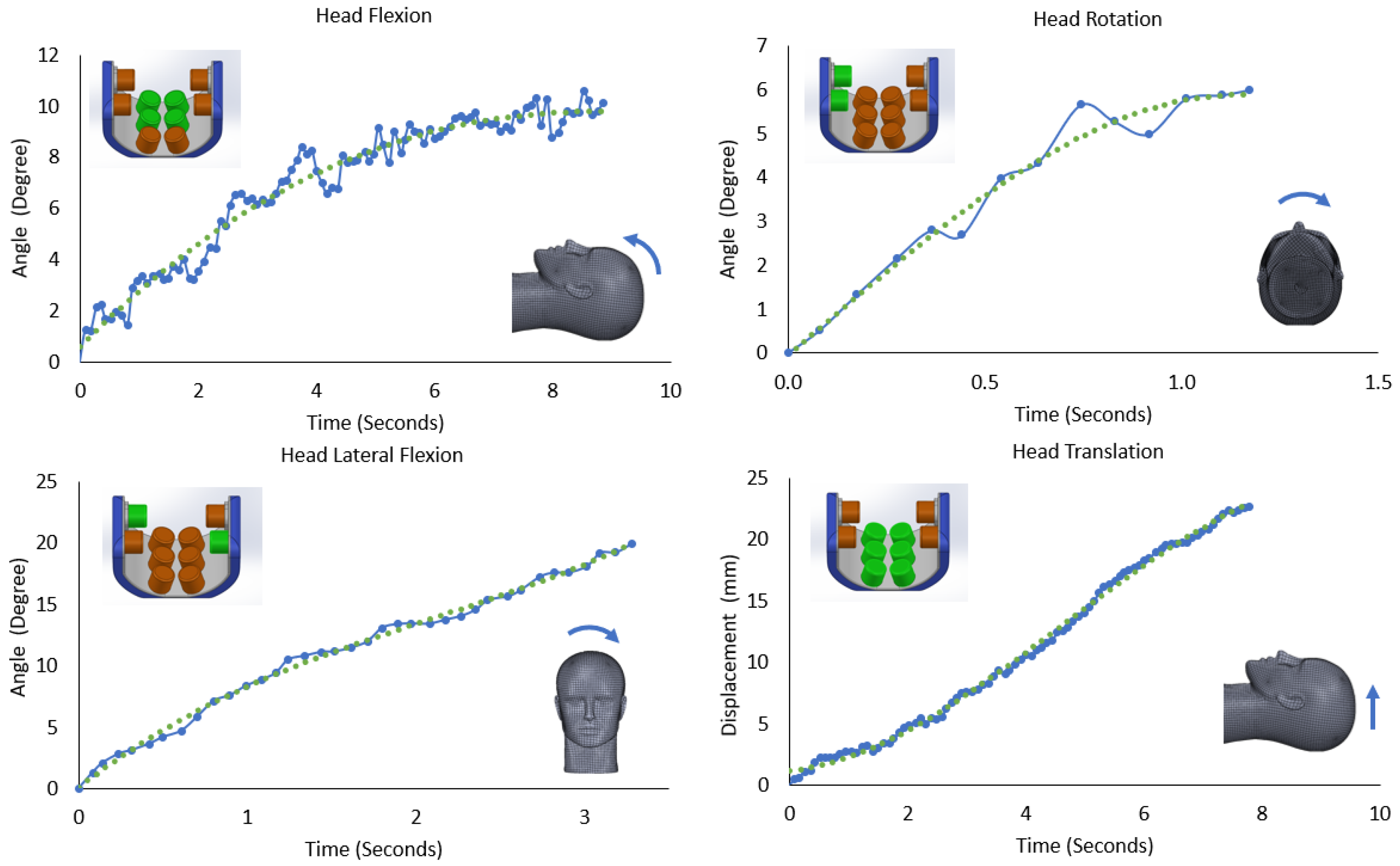
4.4. 4-DoF Multi-Actuator H&N Positioning System

The same experimental head positioning setup and camera (Figure 6) are used to obtain different head movements. By inflating different actuator configurations, 4 DoF head movement is achieved. Figure 9 shows three head rotations (flexion, rotation, and lateral flexion) and one head translation movement.

4.5. Discussion

The single actuator expansion from the simulation is validated using experimental data for free and under loading conditions. The results are promising, as the average expansion deviation is 0.45 mm. The cause of this deviation may be due to the material parameters assigned during simulation studies. The results from the single actuator model validation show a maximum of 1 mm deviation. Two different ML models are tested to create a single actuator model. The deviation can be further improved by testing more ML models.
In this manuscript, the main goal is to test the actuator performance and capabilities for specifically H&N positioning system applications. Therefore, weight ranges were determined based on the human head weight. The single actuator is tested for a maximum of 2000 g weight in this work. To ensure the actuator’s behavior under extreme loading conditions, a 4000 g weight, which is two times more than the tested weight, was used to observe its performance with no pressure and with a pressure of 55 kPa. In the case of no pressure, the actuator did not exhibit any collapsing behavior or structural deformation. When the pressure was 55 kPa, the actuator could still expand by more than 10 mm. These preliminary data show that the actuator can perform under extreme loading conditions with a limited range of motion. In the case of higher operational load, the actuator’s geometrical structure or the material can be changed based on the application requirements.
The maximum deviation between the target flexion angle and the measured angle for the multi-actuator system modeling is 0.5°. These deviations may be due to the assumption of equal head weight distribution during multi-actuator modeling. To achieve higher accuracy, the weight estimation on each actuator is needed so that each actuator can be pressurized according to the weight it experiences. Thus, we may need four different pressures rather than two, which is assumed in this study, for head flexion. Additionally, the multi-actuator system model is validated for only head flexion movements. However, this system is capable of 4 DoF head movements, as shown in Figure 9. To ensure comprehensive coverage of the multi-system model, it is necessary to validate other types of rotation and translation head movements.
Furthermore, the geometrical features of the head positioning system are extracted from the experimental setup and the CAD models in this study. The head that has been used during the multi-actuator experimental study may not represent the real human head due to the non-bony structure, the joint location, and the H&N shape during supine position. However, during clinical practice with patients, these features will be extracted from the MRI images, which can provide higher accuracy. The MRI images will provide the head size and its position with respect to the head positioning system.

5. Conclusions

This paper demonstrates a novel soft corrugated actuator design suited to create a head positioning system for head and neck cancer radiation therapy. The presented design of the actuator can produce linear expansion during free/loading conditions needed for the required movement of the head. Expansion of the actuator is validated through simulations and benchtop experiments. The actuator model is created to predict the pressure needed for desired expansion under loading conditions. A preliminary system is created for achieving multi DoF head movements. Four actuators of the system are actuated in parallel to move the head at the desired flexion angle using the predicted pressure values from the single actuator model. This verifies the approach of the single actuator model to be used in the multi-actuators in a parallel configuration. Finally, benchtop testing confirms that the ten actuators’ configuration can move the head in all 4 DoF (three rotations and one translation). In the future, single actuator design can be further optimized to achieve higher expansion with sufficient linearity, which can create a higher range of head movements. Also, by optimizing actuator configurations in the system, additional DoF, such as head side translation, can be achieved. The ML models can be used to develop precise control algorithms for the head positioning system.

Author Contributions

Conceptualization, V.E., S.S. and I.S.; methodology, V.E., S.S. and I.S.; validation, V.E., S.S. and I.S.; data curation, V.E., S.S. and I.S.; writing—original draft preparation, V.E., S.S., I.S. and M.B.J.W.; writing—review and editing, V.E., S.S., I.S., A.P., F.T., S.H.N., S.J., H.P., N.G. and M.B.J.W.; supervision, V.E., I.S., N.G. and M.B.J.W. All authors have read and agreed to the published version of the manuscript.

Funding

This research received no external funding.

Institutional Review Board Statement

Not applicable.

Informed Consent Statement

Not applicable.

Data Availability Statement

The raw data supporting the conclusions of this article will be made available by the authors on request.

Acknowledgments

The authors would like to thank the UT Arlington Research Institute for providing support for this research. Also, we want to thank Suyog Neupane for his support and contribution during data collection.

Conflicts of Interest

The authors declare no conflicts of interest.

Abbreviations

The following abbreviations are used in this manuscript:
MLMachine Learning
DoFDegrees of Freedom
H&NHead and Neck
Std DevStandard Deviation
MSEMean Squared Error
KNNK-Nearest Neighbor
SVDSingular Value Decomposition
PCAPrincipal Component Analysis

References

  1. Skorina, E.H.; Onal, C.D. Soft Pneumatic Actuators: Modeling, Control, and Application. In Smart Materials: Considerations on Earth and in Space; Springer: Cham, Germany, 2022; pp. 129–219. [Google Scholar]
  2. Erel, V.; Singh, I.; Lindsay, A.R.; Shi, W.Y.; Wijesundara, M.B. Development and Characterization of a Modular Soft Actuator Enabled Elbow Exoskeleton for Assistive Movements. In International Design Engineering Technical Conferences and Computers and Information in Engineering Conference; American Society of Mechanical Engineers: New York, NY, USA, 2021; Volume 85444, p. V08AT08A046. [Google Scholar]
  3. Singh, I.; Erel, V.; Gu, Y.; Lindsay, A.R.; Patterson, R.M.; Swank, C.; Wijesundara, M.B. Development of Soft Pneumatic Actuator Based Wrist Exoskeleton for Assistive Motion. In Proceedings of the 2023 IEEE/ASME International Conference on Advanced Intelligent Mechatronics (AIM), Seattle, WA, USA, 27 June–1 July 2023; pp. 359–366. [Google Scholar]
  4. Runciman, M.; Darzi, A.; Mylonas, G.P. Soft robotics in minimally invasive surgery. Soft Robot. 2019, 6, 423–443. [Google Scholar] [CrossRef] [PubMed]
  5. Xavier, M.S.; Tawk, C.D.; Zolfagharian, A.; Pinskier, J.; Howard, D.; Young, T.; Lai, J.; Harrison, S.M.; Yong, Y.K.; Bodaghi, M.; et al. Soft pneumatic actuators: A review of design, fabrication, modeling, sensing, control and applications. IEEE Access 2022, 10, 59442–59485. [Google Scholar] [CrossRef]
  6. Peng, Y.; Nabae, H.; Funabora, Y.; Suzumori, K. Peristaltic transporting device inspired by large intestine structure. Sens. Actuators A Phys. 2024, 365, 114840. [Google Scholar] [CrossRef]
  7. Peng, Y.; Sakai, Y.; Nakagawa, K.; Funabora, Y.; Aoyama, T.; Yokoe, K.; Doki, S. Funabot-Suit: A bio-inspired and McKibben muscle-actuated suit for natural kinesthetic perception. Biomim. Intell. Robot. 2023, 3, 100127. [Google Scholar] [CrossRef]
  8. Erel, V.; Lindsay, A.R.; Singh, I.; Wijesundara, M.B. Corrugated Diaphragm Actuator for Soft Robotic Applications. J. Mech. Des. 2022, 144, 045001. [Google Scholar] [CrossRef]
  9. Facing Cancer Head-On NIH. Available online: https://www.nidcr.nih.gov/news-events/nidcr-news/2024/facing-cancer-head (accessed on 5 August 2024).
  10. 2024 Head & Neck Cancer Data and Resources. Available online: https://www.nevadacancercoalition.org/blog/2024-head-neck-cancer-data-and-resources (accessed on 5 August 2024).
  11. Xing, L.; Lin, Z.X.; Donaldson, S.S.; Le, Q.T.; Tate, D.; Goffinet, D.R.; Wolden, S.; Ma, L.; Boyer, A.L. Dosimetric effects of patient displacement and collimator and gantry angle misalignment on intensity modulated radiation therapy. Radiother. Oncol. 2000, 56, 97–108. [Google Scholar] [CrossRef] [PubMed]
  12. Manning, M.A.; Wu, Q.; Cardinale, R.M.; Mohan, R.; Lauve, A.D.; Kavanagh, B.D.; Morris, M.M.; Schmidt-Ullrich, R.K. The effect of setup uncertainty on normal tissue sparing with IMRT for head-and-neck cancer. Int. J. Radiat. Oncol. Biol. Phys. 2001, 51, 1400–1409. [Google Scholar] [CrossRef] [PubMed]
  13. Kim, S.; Akpati, H.C.; Li, J.G.; Liu, C.R.; Amdur, R.J.; Palta, J.R. An immobilization system for claustrophobic patients in head-and-neck intensity-modulated radiation therapy. Int. J. Radiat. Oncol. Biol. Phys. 2004, 59, 1531–1539. [Google Scholar] [CrossRef] [PubMed]
  14. Cerviño, L.I.; Detorie, N.; Taylor, M.; Lawson, J.D.; Harry, T.; Murphy, K.T.; Mundt, A.J.; Jiang, S.B.; Pawlicki, T.A. Initial clinical experience with a frameless and maskless stereotactic radiosurgery treatment. Pract. Radiat. Oncol. 2012, 2, 54–62. [Google Scholar] [CrossRef] [PubMed]
  15. Cervino, L.I.; Pawlicki, T.; Lawson, J.D.; Jiang, S.B. Frame-less and mask-less cranial stereotactic radiosurgery: A feasibility study. Phys. Med. Biol. 2010, 55, 1863. [Google Scholar] [CrossRef] [PubMed]
  16. Wiersma, R.D.; Wen, Z.; Sadinski, M.; Farrey, K.; Yenice, K.M. Development of a frameless stereotactic radiosurgery system based on real-time 6D position monitoring and adaptive head motion compensation. Phys. Med. Biol. 2009, 55, 389. [Google Scholar] [CrossRef] [PubMed]
  17. Ogunmolu, O.; Kulkarni, A.; Tadesse, Y.; Gu, X.; Jiang, S.; Gans, N. Soft-NeuroAdapt: A 3-DOF neuro-adaptive patient pose correction system for frameless and maskless cancer radiotherapy. In Proceedings of the 2017 IEEE/RSJ International Conference on Intelligent Robots and Systems (IROS), Vancouver, BC, Canada, 24–28 September 2017; pp. 3661–3668. [Google Scholar]
  18. Ogunmolu, O.; Liu, X.; Gans, N.; Wiersma, R.D. Mechanism and model of a soft robot for head stabilization in cancer radiation therapy. In Proceedings of the 2020 IEEE International Conference on Robotics and Automation (ICRA), Paris, France, 31 May–31 August 2020; pp. 4609–4615. [Google Scholar]
  19. Available online: https://www.smooth-on.com/products/pmc-724/ (accessed on 10 September 2024).
  20. Blaber, J.; Adair, B.; Antoniou, A. Ncorr: Open-source 2D digital image correlation matlab software. Exp. Mech. 2015, 55, 1105–1122. [Google Scholar] [CrossRef]
  21. Benoit, K. Linear regression models with logarithmic transformations. Lond. Sch. Econ. Lond. 2011, 22, 23–36. [Google Scholar]
  22. Deprez, M.; Robinson, E.C. Machine Learning for Biomedical Applications: With Scikit-Learn and PyTorch; Elsevier Science: Amsterdam, The Netherlands, 2023. [Google Scholar]
  23. VanderPlas, J. Python Data Science Handbook: Essential Tools for Working with Data; O’Reilly Media: Sebastopol, CA, USA, 2017. [Google Scholar]
  24. Ostertagová, E. Modelling using polynomial regression. Procedia Eng. 2012, 48, 500–506. [Google Scholar] [CrossRef]
  25. Montesinos López, O.A.; Montesinos López, A.; Crossa, J. Overfitting, model tuning, and evaluation of prediction performance. In Multivariate Statistical Machine Learning Methods for Genomic Prediction; Springer International Publishing: Cham, Germany, 2022; pp. 109–139. [Google Scholar]
  26. Arslan, M.; Guzel, M.; Demirci, M.; Ozdemir, S. SMOTE and gaussian noise based sensor data augmentation. In Proceedings of the 2019 4th International Conference on Computer Science and Engineering (UBMK), Samsun, Turkey, 11–15 September 2019; pp. 1–5. [Google Scholar]
  27. Fonti, V.; Belitser, E. Feature selection using lasso. Amst. Res. Pap. Bus. Anal. 2017, 30, 1–25. [Google Scholar]
  28. Hackeling, G. Mastering Machine Learning with Scikit-Learn; Packt Publishing Ltd.: Birmingham, UK, 2017. [Google Scholar]
Figure 1. Preliminary design of multi-actuator H&N positioning system.
Actuators 13 00351 g001
Figure 2. Corrugated actuator’s 3D and cross-sectional views with critical dimensions.
Actuators 13 00351 g002
Figure 3. Single actuator experimental setup.
Actuators 13 00351 g003
Figure 4. Pressure vs. displacement plot with different weights.
Actuators 13 00351 g004
Figure 5. Degree of polynomial vs. mean squared error plot.
Actuators 13 00351 g005
Figure 6. Head positioning system and camera view.
Actuators 13 00351 g006
Figure 7. Figure on the left: geometric relations between the joint, head, and actuators. Figure on the right: head positioning setup with pressurized actuators for model validation.
Actuators 13 00351 g007
Figure 8. Experiment and simulation results for single actuator free expansion, showing pressure versus displacement, with cross-sectional views of both normal and pressurized actuators.
Actuators 13 00351 g008
Figure 9. Three head rotation angles and one translation plots by inflating different actuator configurations.
Actuators 13 00351 g009
Table 1. Corrugated actuator dimensions.
DimensionsActuator
h t (mm)50
h c (mm)14
d o (mm)60
d i (mm)30
t w (mm)4
t c (mm)5
θ (degree)65°
Table 2. MSE and R2 score results of polynomial regression and KNN-CV models.
ModelMean Squared ErrorR2 Score
Polynomial Regression0.15380.9050
KNN-CV0.10150.9914
Table 3. Single actuator expansion under loading results comparison (experiment vs. simulation).
Weight (g)Expansion from Experiment (mm)Expansion from Simulation (mm)Expansion Deviation (mm)
022.6622.050.61
50021.2220.680.54
100019.9819.670.31
150018.8918.350.54
200017.4017.130.27
Table 4. Input vs. measured displacements with displacement deviations.
Input Weight (g)Input Displacement (mm)Predicted Pressure (kPa)Experimentally Measured Displacement (mm)Displacement Deviation (mm)
300616.8860
6001033.14111
700415.0231
950216.8120
10002.533.2720.5
15007.515.0270.5
1800416.9531
20001015.0991
Table 5. Predicted pressures with target vs. measured angle values.
Predicted P1 (kPa)Predicted P2 (kPa)Target Angle (degree)Measured Angle (degree)
17.0124.522.00°1.79°
32.5235.964.00°3.78°
35.7553.326.00°5.50°
51.8862.018.00°7.62°
Disclaimer/Publisher’s Note: The statements, opinions and data contained in all publications are solely those of the individual author(s) and contributor(s) and not of MDPI and/or the editor(s). MDPI and/or the editor(s) disclaim responsibility for any injury to people or property resulting from any ideas, methods, instructions or products referred to in the content.

