Article

Study on the Vibration Reduction Effect of Piezoelectric Actuation on Flexible Tilting Pad Bearings with Different Structural Parameters

School of Mechatronic Engineering and Automation, Shanghai University, Shanghai 200444, China
*
Author to whom correspondence should be addressed.
Actuators 2024, 13(9), 365; https://doi.org/10.3390/act13090365
Submission received: 16 August 2024 / Revised: 11 September 2024 / Accepted: 17 September 2024 / Published: 19 September 2024
(This article belongs to the Section Control Systems)

Abstract

:
To improve the vibration performance of oil-lubricated tilting pad bearing systems, this paper investigates the impact of different structural parameters on the vibration reduction effect of piezoelectric actuators on flexible tilting pad bearings. Four sets of flexible tilting pad bearings were designed and manufactured, including a flexible hinge tilting pad bearing and three sets of double-layer spring-supported flexible tilting pad bearings with different parameters. The radial displacement of the bearing load pad was controlled to varying degrees using a piezoelectric actuator, and semi-active control experiments were conducted on the flexible tilting pad bearings. The experimental results show that appropriately reducing the radial clearance and the stiffness of the bearing’s flexible structure can effectively suppress vibrations, enhance the vibration reduction effect of the piezoelectric actuation, and increase the stability of the bearing-rotor system. This study is of significant importance for the design of flexible tilting pad bearings and the vibration suppression of rotor systems.

1. Introduction

Sliding bearings are generally used in energy facilities, such as steam turbine generators, hydroelectric generators, and nuclear power units. They are one of the most important components in rotating machinery [1]. Due to the highly stable adaptive adjustment performance of tilting pad bearings [2,3], they have been widely used in high-speed rotating machinery. With the rapid technological advancements in recent years, achieving a high speed, high load, and high precision has become the development goal of rotating equipment. Therefore, higher demands have been placed on the vibration reduction performance and the stability of sliding bearing-rotor systems [4]. To meet these challenges, exploring new vibration control methods is essential.
Currently, research on vibration suppression technology mainly focuses on passive control and active control. Passive control technology, as an important method in current engineering practice, mainly relies on dynamic vibration absorbers, additional damping structures, and optimized dynamic designs to achieve vibration control. Many scholars have attempted to reduce vibration by altering the structure or surface morphology of bearings. For example, converting unstable bearing pads to fixed pad structures has been shown to reduce rotor vibration during operation [5]. Alternatively, modifying the pivot of the bearing pads using flexible hinge supports simplifies the bearing structure while still maintaining the superior performance of tilting pad bearings [6,7,8]. Recent studies have demonstrated that surface texturing on the outer surface of the spindle or the inner surface of the bearing can alter the distribution and flow of the lubricating oil. Niu et al. [9] found that appropriate localized textures can have a more significant impact during high-speed operation, exhibiting better vibration suppression effects than fully textured surfaces. However, the essence of these innovations lies in applying traditional passive control techniques to mitigate vibration in rotor systems, which has certain limitations and cannot sustain vibration reduction over extended periods. Moreover, when the spindle is rotating at high or ultra-high speeds, it remains susceptible to vibrations caused by external disturbances or inherent residual imbalances. Therefore, external control measures must be adopted to effectively mitigate vibration.
Active control technology with the capability for active adjustment and a wide adaptive frequency range has become a research hotspot [10]. Active control technology mainly relies on multi-sensor technology to monitor the bearing-rotor status in real time and then perform feedback control. It can flexibly adapt to external disturbances and system uncertainties, possessing advantages such as a rapid response, intelligence, and stability. In recent years, the development of smart material structures has greatly promoted the research and application of active vibration control technology. Currently, smart materials used for active vibration suppression mainly include shape memory alloys [11,12], electrorheological/magnetorheological fluids [13,14], magnetostrictive materials [15], and piezoelectric materials [16]. Among them, piezoelectric materials, as actuators, have numerous advantages, such as a fast frequency response, wide control frequency range, high displacement resolution, small size, easy integration, and no mechanical friction [17]. They have been widely used in active vibration suppression systems.
Morosi and Santos [18] introduced piezoelectric actuators into gas journal bearings to control throttling parameters and actively control rotor vibrations. Mizumoto et al. [19] embedded piezoelectric actuators in each elastic region of the tilting pad gas bearings, causing the bearing surface to deform and form a wedge-shaped region in the gas gap. The experimental results showed that as the voltage applied to the piezoelectric actuator increased, the wedge angle of the bearing surface increased, generating an aerodynamic force that caused the spindle to displace, thus suppressing the spindle vibrations. Chen et al. [20] proposed a novel hybrid bearing that introduces piezoelectric controllers and actively controls the pre-tightening coefficient of the tilting pads to suppress the vibrations, verifying the linear relationship between the driving force, voltage, and elongation of the piezoelectric actuator. Yan et al. [21] established an optimal control model by embedding piezoelectric actuators in the pivots of each tilting pad bearing. When a voltage is applied to the actuators, the pads can generate small displacements behind their radial pivots to change the air film force between the journal and the pad. The numerical control results showed that this optimal control system could effectively suppress the unbalanced response of the system. Da Silveira et al. [22,23] analyzed the feasibility of coupling piezoelectric collectors on tilting pad bearings, verifying that piezoelectric collectors can be assembled on bearings without affecting their dynamic behavior and determining that the collected energy is sufficient for state-monitoring sensors. Girish et al. [24] also simulated the controlled motion when each tilting pad was controlled to an equal position, where the pads translated radially and tilted. The results showed that the negative adjustments to the radial and pad tilting movements could produce better stability margins under a higher eccentricity. Peng et al. [25] found that by controlling the variables related to the circumferential angle and the radial displacement of the bearing pad, the amplitude of the rotor journal could be significantly reduced, thereby improving the vibration performance of the novel flexible tilting pad bearing-rotor system. Most current research focuses on the active control strategies [26,27,28] and methods of piezoelectric actuators in rotor systems.
Huang et al. [29] proposed a new double-layer flexible support tilting pad bearing that can effectively reduce the amplitude of acceleration and displacement, improving the rotor stability. Based on this research, this paper mainly studies the effect of different radial clearances and spring stiffnesses on the vibration reduction effect of piezoelectric actuators in flexible tilting pad bearings. By controlling oil-lubricated flexible tilting pad bearings with different structural parameters using piezoelectric actuators, the radial displacement of the tilting pad bearing is adjusted to achieve vibration control. This study provides a reference for the structural design of the double-layer flexible support tilting pad bearing and improves the vibration performance of the bearing-rotor system.

2. Experimental Procedure

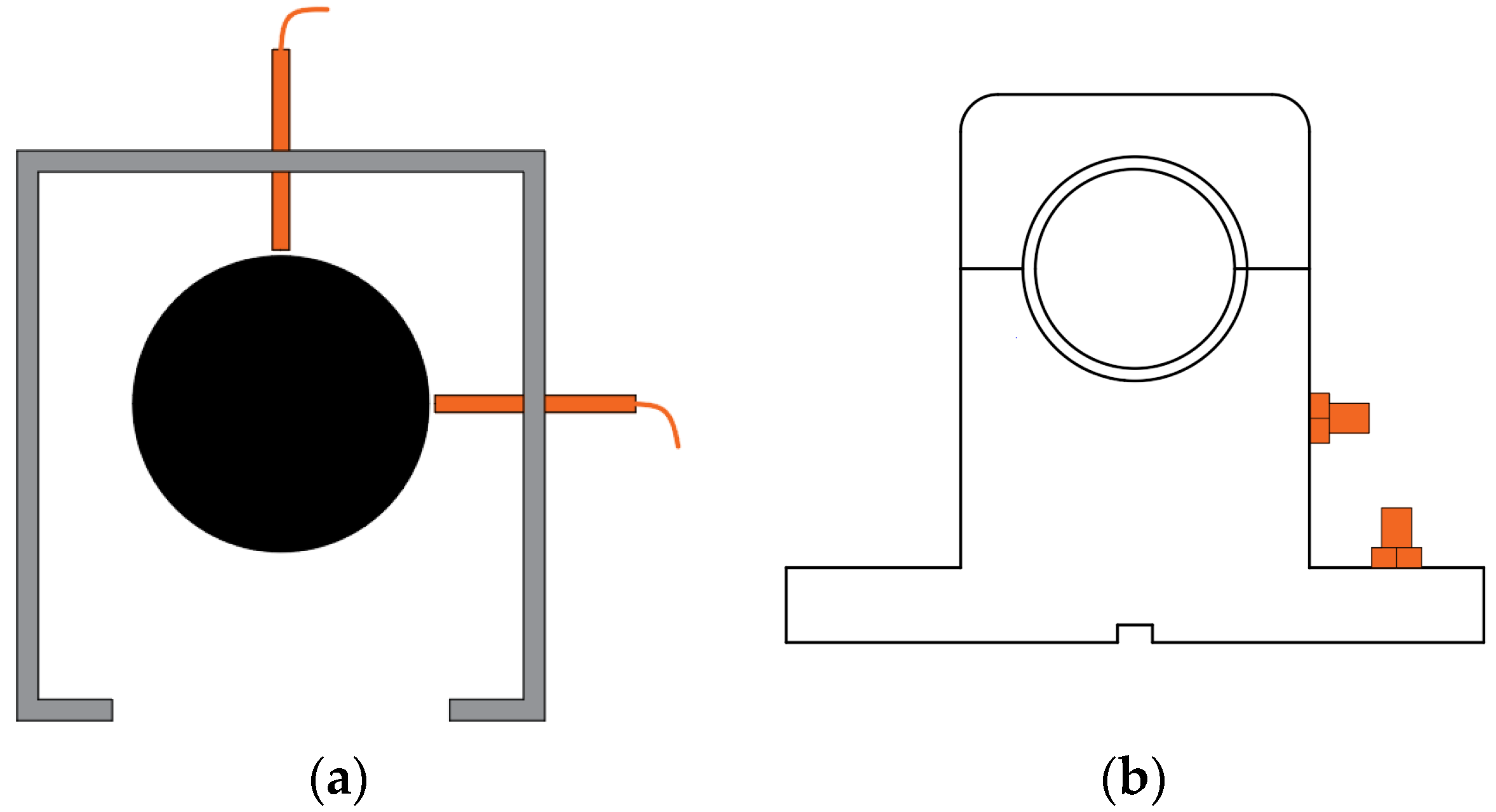
2.1. Design of the Flexible Tilting Pad Bearing Structure and Piezoelectric Drive Structure

Figure 1a shows a schematic diagram of a flexible pivot journal bearing (FPJB). The support structure is a flexible pivot, which allows the rotor to cause the bearing pad to deflect during operation. The pivot’s structural stiffness is moderate, allowing it to automatically adjust the deflection angle according to changes in the oil film force.
Figure 1b shows a schematic diagram of the double-layer flexible support tilting pad bearing (DL-FSTPB). The inner layer spring consists of a pair of asymmetrically arranged integral springs, while the outer layer spring comprises a pair of symmetrically arranged integral springs [29]. The primary function of the upper offset spring is to increase the fluid lubrication wedge gap and maximize the load capacity. The symmetrically arranged springs in the lower layer provide radial stiffness to the bearing system, thus altering the bearing’s stiffness [29]. The bearing material is 40CrMo, which has a high yield strength, tensile strength, and toughness. The bearing is manufactured using wire cutting, allowing for high-precision spring and hinge structures.
To achieve active control and improve the vibration level of the tilting pad bearing- rotor system, a piezoelectric-driven DL-FSTPB is used. As shown in Figure 1b, two piezoelectric actuators are installed on the back of the outer layer symmetric spring pads of DL-FSTPB. They are positioned at 45° to the left and right of the support pad. The piezoelectric actuators can push the symmetric spring structure to achieve active control of the radial displacement of the bearing pad.
Table 1 presents the basic parameters of the bearing. To further explore the impact of the different parameters of DL-FSTPB on the tilting pad bearing-rotor system and further improve the vibration level of the oil-lubricated tilting pad bearing-rotor system, DL-FSTPBs with different radial clearances and different spring stiffnesses are proposed. The specific parameters are shown in Table 2.

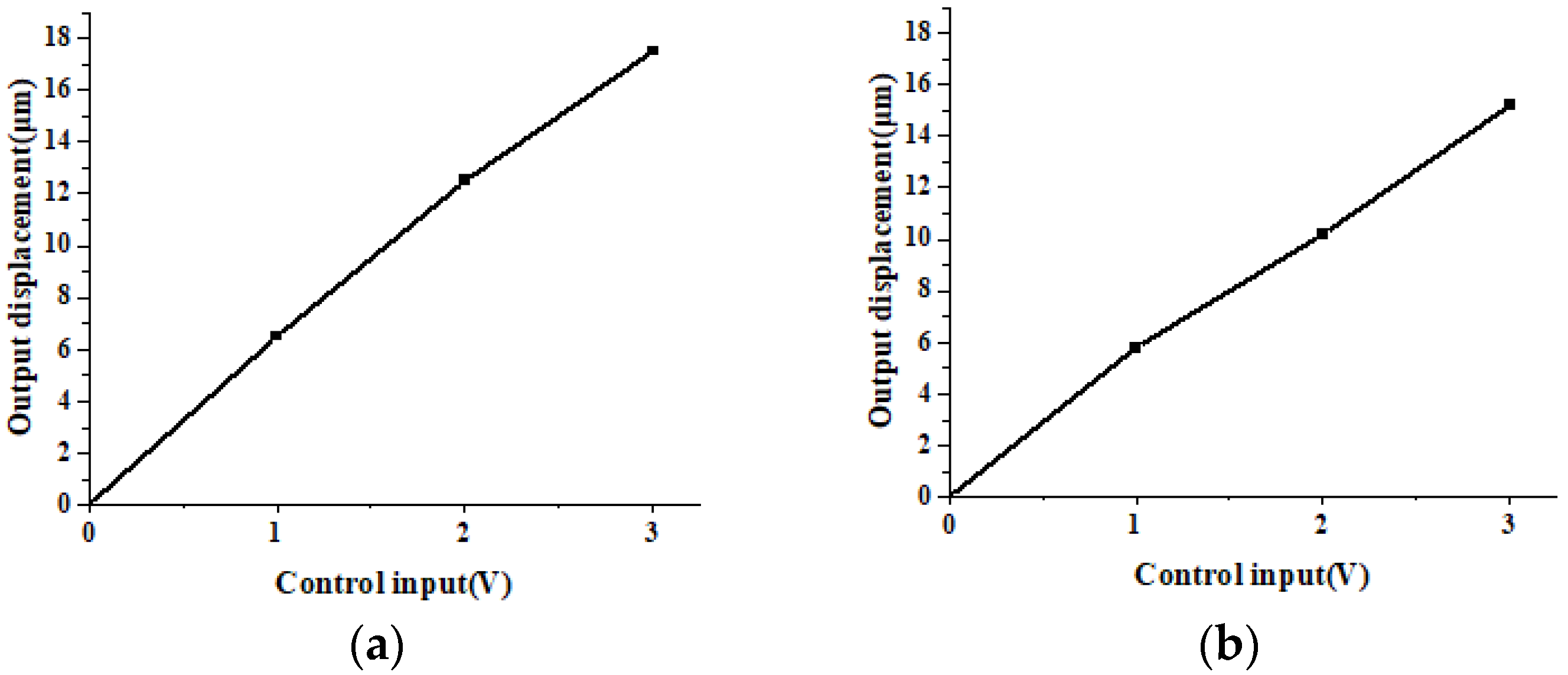
2.2. Calibration of the Piezoelectric Actuator

The piezoelectric actuator used in this experiment is the PSt150/5/40VS10 model, equipped with an XE-501c controller (Harbin Core Tomorrow Science & Technology Co., Ltd., Harbin, China). The factory parameters are shown in Table 3.
The installation positions of the two piezoelectric actuators are shown in Figure 1b, where they are mounted on the back of the bearing lower shell and secured with fixtures, such as sleeves. A dial gauge is clamped to a magnetic stand, with the gauge head placed on the bearing surface to monitor the radial position of the bearing in real time. The control signals are supplied to the piezoelectric controller at intervals of 1 V, and the values from the micrometer are recorded three times and averaged. Although the output displacement of the piezoelectric actuator exhibits nonlinear characteristics, in this study, the working range of the piezoelectric actuator is very small. The results are shown in Figure 2. It can be seen that the output displacements of the two bearings are nearly linear with respect to the input voltage of the piezoelectric actuator.
The piezoelectric ceramic actuator needs to be driven and controlled using a piezoelectric ceramic controller, as shown in Figure 3. An external analog signal power source is connected to the CONTROL INPUT terminal on the front panel via an input cable, while the piezoelectric ceramic actuator is connected to the PZT OUTPUT terminal on the front panel. The external signal at the control input terminal can regulate the voltage at the output terminal, thereby controlling the displacement of the piezoelectric actuator.

2.3. Composition of the Experimental Setup

Figure 4 shows the rotor-bearing system experimental device. The rotor system consists of a main shaft supported by a pair of experimental bearings, driven by an adjustable-speed high-speed electric spindle through flexible coupling. The high-speed electric spindle is controlled by a frequency converter (VFD150B43A), fixed by an adjustable position frame, and cooled by a water circulation cooling system, providing a speed range of 0–12,000 r/min. The oil supply system consists of a 5 L oil tank, an oil pump, and oil supply pipelines, and is capable of stably providing 0.1 MPa oil pressure, ensuring stable and flowing lubricating oil for the test system. When the shaft begins to rotate, a dynamic pressure oil film forms between the test bearing and the rotating shaft, generating an oil film force to support the rotor system. The oil circulation system, oil station, and speed adjustment of the electric spindle are all controlled and displayed by the console.
The basic structure of the loading device is shown in Figure 4. The loading device uses weights for loading, where standard mass weights are used during the performance experiments of the test bearing. The loading system includes a support frame, fixed pulleys, and a steel wire tension rope. The specific loading scheme is as follows: the steel wire rope is wound around the test bearing and connected to the fixed pulley. The other end of the steel wire tension rope is connected to a standard mass weight, keeping the steel wire rope in a freely taut state. In this way, the weight’s gravity is converted into the rope’s tensile force acting on the test bearing through the fixed pulley, achieving static force loading on the flexible tilting pad radial sliding bearing. The advantage of weight loading compared with other loading schemes is that the weight has a standard mass, providing high precision and control, with stable and almost no fluctuation in tensile force, ensuring strong reliability.
Figure 5a shows the installation method of the displacement sensors, which are fixed on the sensor bracket and tightened with nuts, positioned horizontally and vertically at the journal to track the motion trajectory of the journal center in real time. As shown in Figure 5b, the acceleration sensors are glued to the bottom of the bearing seat, monitoring the vibration signals in the horizontal and vertical directions. ISO-VG32 grade lubricating oil was used in the experiment and was delivered to the bearing through the oil supply pipeline from the top of the bearing seat. Table 4 lists some of the working conditions’ parameters of the bearing-rotor system.

3. Experimental Results and Discussion

To investigate the impact of different spring stiffnesses and radial clearances of DL-FSTPB on the vibration performance of tilting pad bearing-rotor systems under various control voltages, and to further improve the vibration level of oil-lubricated tilting pad bearing-rotor systems, an experimental analysis was conducted on DL-FSTPBs with different parameters, listed in Table 1, under various experimental conditions.

3.1. The Effect of Spring Stiffness on Vibration Performance

In order to study the influence of different spring stiffnesses on the vibration reduction performance of flexible tilting pad bearings driven by piezoelectric actuators, experimental analyses were conducted on DL-FSTPB with a spring stiffness of 2.4 × 10⁶ N/mm and DL-FSTPB-1 with a spring stiffness of 1.6 × 10⁶ N/mm under two loading conditions.

3.1.1. Loading Condition of 100 N

To deeply investigate the stability performance of bearings with different spring stiffnesses at specific speeds, a comparative analysis of the full time–domain vibration amplitude plots and displacement spectrum plots for the non-motor ends of the two bearings was conducted. Additionally, elliptical filtering techniques were applied for data processing. As shown in Figure 6, at a rotational speed of 4000 r/min, the rotor vibration amplitude of the DL-FSTPB-1 bearing is significantly lower overall than that of the DL-FSTPB bearing. Figure 7 shows that, regardless of the control voltage applied, the displacement amplitude of DL-FSTPB-1, which has a lower stiffness, is smaller than that of DL-FSTPB. This strongly demonstrates that appropriately reducing the stiffness is beneficial for lowering the vibration amplitude and preventing various faults caused by vibrations.

3.1.2. Loading Condition of 300 N

The shaft center trajectory, which represents the movement path of the shaft center over a specific time period, accurately maps the operational state of the rotor at a constant speed. Figure 8 clearly shows the comparison of the shaft center trajectories for the two bearings under different speeds and control displacements with a 300 N load. The elliptical shape of the trajectories indicates stable and smooth rotor operation. It can be clearly observed from the figure that at speeds of 4000 r/min, 5000 r/min, and 6000 r/min, as the control voltage gradually increases, that is, the radial push displacement of the bearing pad increases, the areas of the shaft center trajectories of both bearings show a significant shrinking trend. Notably, the shaft center trajectory area of DL-FSTPB-1 with a lower spring stiffness is consistently smaller than that of DL-FSTPB with a higher spring stiffness.
By comparing the vibration effects of two bearings with different spring stiffnesses under various loading conditions, it can be concluded that the additional load in the rotor system alters the dynamic characteristics of the oil film. Under both loading conditions, the experimental results show a similar trend, with DL-FSTPB-1 effectively reducing the displacement amplitude. This indicates that reducing the spring stiffness of the bearing can decrease the resonance and operating amplitude of the rotor, thereby enhancing the rotor stability and reducing the amplitude through piezoelectric actuation.

3.2. The Effect of Radial Clearance on Vibration Performance at Different Speeds

To explore the effect of different radial clearances on the vibration reduction performance of flexible tilting pad bearings driven by piezoelectric actuators, experimental analyses were conducted on DL-FSTPB with a radial clearance of 0.05 mm and DL-FSTPB-2 with a radial clearance of 0.0375 mm under two loading conditions.

3.2.1. Loading Condition of 100 N

A wavelet analysis can capture the local features of signals more accurately and effectively in both the time and frequency domains. Figure 9 presents the time–frequency distribution of the horizontal acceleration signal for bearings with different radial clearances under a 100 N load. The horizontal axis represents the time during which the acceleration signal was collected. The strength of the vibration energy is visually represented by the color intensity in the figure, with red indicating the most intense vibration energy, green representing about half of the maximum vibration energy, and blue serving as the background color, indicating the weakest vibration energy.
By comparing the fundamental frequency peak energy of DL-FSTPB and DL-FSTPB-2 with a smaller radial clearance in Table 5, at a speed of 4000 r/min, the maximum energy of the fundamental frequency decreases from 8.205 (DL-FSTPB) to 7.429 (DL-FSTPB-2), a reduction of 9.46%. At speeds of 5000 and 6000 r/min, the percentage reductions in the fundamental frequency energy are 14.82% and 30.85%, respectively. This indicates that DL-FSTPB-2 has a good vibration reduction performance, and the effect is more pronounced at higher speeds. Therefore, a moderately smaller radial clearance helps to reduce vibration and enhance rotor stability.

3.2.2. Loading Condition of 300 N

Figure 10 shows the comparison of the shaft center trajectories for DL-FSTPB and DL-FSTPB-2 with different radial clearances under a 300 N load at different speeds. It can be clearly observed from the figure that after surpassing the critical speed of 4000 r/min, the areas of the shaft center trajectories for both bearings show a shrinking trend. The area of the shaft center trajectory of DL-FSTPB-2 with a smaller radial clearance is always smaller than that of DL-FSTPB with a larger radial clearance.
By comparing the vibration effects of bearings with different radial clearances under various loading conditions, it can be concluded that the experimental results exhibit similar trends under both load conditions. The shaft center trajectory area of DL-FSTPB-2 with a smaller radial clearance significantly decreases, and the peak of the fundamental frequency energy almost disappears. This indicates that reducing the radial clearance can improve the vibration reduction performance of the bearing and better enhance the vibration reduction effect of piezoelectric actuation. When the radial clearance decreases, the inclination of the pad increases, causing the journal to approach the center of the bearing, thereby improving the amplitude.

3.3. The Combined Effects of Spring Stiffness and Radial Clearance on Vibration under Different Control Voltages

To investigate the combined effect of different spring stiffnesses and radial clearances on the vibration reduction performance of flexible tilting pad bearings driven by piezoelectric actuators, experimental analyses were conducted on DL-FSTPB with a spring stiffness of 2.4 × 10⁶ N/mm and a radial clearance of 0.05 mm, and on DL-FSTPB-3 with a spring stiffness of 1.6 × 10⁶ N/mm and a radial clearance of 0.0375 mm under two loading conditions.

3.3.1. Loading Condition of 100 N

To explore the impact of different control displacements on the fundamental and harmonic vibrations of the rotor under a 100 N load, the displacement spectra at different control voltages were plotted, as shown in Figure 11. It is evident from the figure that the fundamental frequency amplitude of the rotor system decreases as the control voltage increases. The most significant reduction in amplitude is observed at a control voltage of 3 V. Additionally, the fundamental frequency amplitude of the DL-FSTPB-3 bearing, which has a lower spring stiffness and a smaller radial clearance, is consistently lower than that of the DL-FSTPB bearing. These results indicate that appropriately reducing the spring stiffness and radial clearance, in combination, is crucial for suppressing vibrations, enhancing the effect of piezoelectric actuation, and improving the operational stability of the rotor system.

3.3.2. Loading Condition of 300 N

Figure 12 shows the comparison of the axis trajectories of DL-FSTPB and DL-FSTPB-3 with different spring stiffnesses and radius gaps under different control displacements when the rotor is loaded with 300 N. It can be clearly observed from the figure that as the control voltage gradually increases, that is, the radial advancement displacement of the bearing bush continues to increase, the areas of the two bearing axis tracks show an obvious shrinking trend. DL-FSTPB-3 with a small radial clearance and a low spring stiffness showed the best performance under various experimental conditions, which can significantly reduce vibration levels and improve the stability of the bearing-rotor system.
By comparing the piezoelectric control vibration damping conditions of two bearings with different spring stiffnesses and radial clearances under different loads, it can be seen that under the two load conditions, the trend of the experimental results is similar. The DL-FSTPB with a small gap and a low stiffness has the best performance in each. The most outstanding performance was demonstrated under all the experimental conditions. The peak frequency displacement was reduced by 64%, and the axis track area was significantly reduced. This indicates that appropriately reducing the radial clearance and spring stiffness can effectively suppress vibrations, enhance the vibration damping effect of the piezoelectric actuator, and increase the stability of the bearing-rotor system.

4. Conclusions

This paper explores the impact of various structural parameters of flexible tilting pad bearings on the vibration reduction performance of piezoelectric actuation, based on the proven effectiveness of piezoelectric-driven radial displacement in reducing vibrations. The experimental study led to the following conclusions:
  • Four different structural parameter bearings were designed and manufactured. The radial displacement of bearings with different structural parameters was controlled using piezoelectric actuators under 100 N and 300 N loads. The full-time domain vibration amplitude, shaft center trajectories, vibration energy acceleration, and displacement spectra at various speeds were obtained;
  • The dynamic performance of two bearings with different spring stiffnesses was analyzed under 100 N and 300 N load conditions using shaft center trajectories and a time–domain waveform analysis. The results showed that the shaft center trajectories and displacement amplitudes of the rotor system with a lower spring stiffness, the DL-FSTPB-1 bearing, significantly decreased at 4000 r/min, 5000 r/min, and 6000 r/min. This indicates that reducing the bearing stiffness can lower the rotor’s resonance amplitude and operational amplitude, aiding in the reduction of the vibration amplitude via piezoelectric actuation, suppressing spindle vibration, and improving the rotor stability;
  • The acceleration wavelet analysis and shaft center trajectories of two bearings with different radial clearances at various speeds were compared. The results showed that the shaft center trajectory of the DL-FSTPB-2 bearing with a smaller radial clearance was smaller and closer to the bearing center. At 6000 r/min, the trajectory area significantly decreased, and the fundamental frequency energy peak nearly disappeared. This indicates that reducing the radial clearance increases the pad tilt, bringing the journal closer to the bearing center and adjusting the rotor amplitude;
  • Finally, the experiment analyzed the vibration control performance of piezoelectric actuators under different loads for two bearings with different spring stiffnesses and radial clearances. The displacement spectra and shaft center trajectories indicated that the DL-FSTPB-3 bearing with a lower spring stiffness and a smaller clearance showed a 64% reduction in the peak fundamental frequency displacement and a significant decrease in the shaft center trajectory area. This demonstrates that appropriately reducing the radial clearance and spring stiffness effectively suppresses vibrations, enhances the vibration reduction effect of piezoelectric actuation, and increases the stability of the bearing-rotor system.

Author Contributions

Conceptualization, Y.Q.; Methodology, G.H. and X.W.; Software, G.H.; Validation, Y.Q. and X.W.; Formal analysis, Y.Q.; Investigation, G.H. and X.Z.; Resources, X.Z.; Data curation, S.Y. and X.Z.; Writing—original draft, Y.Q.; Writing—review and editing, X.W. and S.Y.; Supervision, X.Z.; Project administration, X.W.; Funding acquisition, X.W. All authors have read and agreed to the published version of the manuscript.

Funding

This research was funded by the National Natural Science Foundation of China, grant number 52075311, and the Shanghai Key Laboratory of Intelligent Manufacturing and Robotics.

Data Availability Statement

All data included in this study are available upon request by contact with the corresponding author.

Conflicts of Interest

The authors declare no conflicts of interest.

References

  1. Zhao, Z.; Ji, F.; Guan, Y.; Yuan, X. Vibration and critical characteristics of the tilting pads journal bearing-rotor system. Ind. Lubr. Tribol. 2018, 71, 295–300. [Google Scholar] [CrossRef]
  2. Delgado, A.; Vannini, G.; Ertas, B.; Drexel, M.; Naldi, L. Identification and Prediction of Force Coefficients in a Five-Pad and Four-Pad Tilting Pad Bearing for Load-on-Pad and Load-Between-Pad Configurations. J. Eng. Gas Turbines Power 2011, 133, 092503. [Google Scholar] [CrossRef]
  3. Suh, J.; Palazzolo, A. Three-Dimensional Dynamic Model of TEHD Tilting-Pad Journal Bearing—Part I: Theoretical Modeling. J. Tribol. 2015, 137, 041703. [Google Scholar] [CrossRef]
  4. Dong, J.; Wang, X.; Zhang, J.; Gu, J. Experimental investigation of dynamic behavior of rotor-bearing system with nitrile rubber support. Proc. Inst. Mech. Eng. Part J J. Eng. Tribol. 2018, 232, 1502–1513. [Google Scholar] [CrossRef]
  5. Hei, D.; Lu, Y.; Zhang, Y.; Lu, Z.; Gupta, P.; Müller, N. Nonlinear dynamic behaviors of a rod fastening rotor supported by fixed–tilting pad journal bearings. Chaos Solitons Fractals 2014, 69, 129–150. [Google Scholar] [CrossRef]
  6. Amamou, A.; Chouchane, M. Nonlinear stability analysis of long hydrodynamic journal bearings using numerical continuation. Mech. Mach. Theory 2014, 72, 17–24. [Google Scholar] [CrossRef]
  7. Feng, K.; Liu, W.; Zhang, Z.; Zhang, T. Theoretical model of flexure pivot tilting pad gas bearings with metal mesh dampers in parallel. Tribol. Int. 2016, 94, 26–38. [Google Scholar] [CrossRef]
  8. Shi, Z.; Jin, Y.; Yuan, X.; Chen, R. Effect of pivot stiffness on nonlinear dynamic characteristics of tilting pad journal bearings. Tribol. Int. 2020, 146, 106222. [Google Scholar] [CrossRef]
  9. Niu, Y. Effects of textured surfaces on the properties of hydrodynamic bearing. Int. J. Adv. Manuf. Technol. 2022, 118, 1589–1596. [Google Scholar] [CrossRef]
  10. Wang, M.; Liao, S.; Fang, X.; Fu, S. Active Vibration Suppression Based on Piezoelectric Actuator. In Piezoelectric Actuators; Cheng, T., Li, J., Eds.; IntechOpen: London, UK, 2022. [Google Scholar] [CrossRef]
  11. Yogaraju, R.; Ravikumar, L.; Saravanakumar, G.; Shravankumar, C.; Kumar, V.A. Feasibility and Performance Studies of a Semi Active Journal Bearing. Procedia Technol. 2016, 25, 1154–1161. [Google Scholar] [CrossRef]
  12. Kim, M.; Heo, J.; Rodrigue, H.; Lee, H.; Pané, S.; Han, M.; Ahn, S. Shape Memory Alloy (SMA) Actuators: The Role of Material, Form, and Scaling Effects. Adv. Mater. 2023, 35, 2208517. [Google Scholar] [CrossRef] [PubMed]
  13. Sarath, S.; Paul, P.S.; Lawrance, G. Characterization and performance analysis of magnetorheological foam damper for vibration control during boring process. Multiscale Multidiscip. Model. Exp. Des. 2024, 7, 837–854. [Google Scholar] [CrossRef]
  14. Sharma, S.C.; Kumar, N. Performance of electro-rheological (ER) lubricant operated hybrid circular thrust pad bearing considering 3D surface irregularities. Tribol. Int. 2023, 185, 108554. [Google Scholar] [CrossRef]
  15. Shang, T.; Huang, Q.; Wang, Y. Vibration reduction and energy harvesting on the ship thrust bearing unit excited by a measured shaft longitudinal vibration using NES-GMM. Ocean. Eng. 2024, 294, 116914. [Google Scholar] [CrossRef]
  16. Manjunath, T.C.; Bandyopadhyay, B. Vibration control of Timoshenko smart structures using multirate output feedback based discrete sliding mode control for SISO systems. J. Sound Vib. 2009, 326, 50–74. [Google Scholar] [CrossRef]
  17. Wang, C.; Xie, X.; Chen, Y.; Zhang, Z. Investigation on active vibration isolation of a Stewart platform with piezoelectric actuators. J. Sound Vib. 2016, 383, 1–19. [Google Scholar] [CrossRef]
  18. Morosi, S.; Santos, I.F. Active lubrication applied to radial gas journal bearings. Part 1: Modeling. Tribol. Int. 2011, 44, 1949–1958. [Google Scholar] [CrossRef]
  19. Mizumoto, H.; Arii, S.; Yabuta, Y.; Tazoe, Y. Vibration control of a high-speed air-bearing spindle using an active aerodynamic bearing. In Proceedings of the ICCAS, Gyeonggi-do, Republic of Korea, 27–30 October 2010; pp. 2261–2264. [Google Scholar]
  20. Chen, R.; Ouyang, W.; Shi, Z.; Wei, Y.; Yuan, X. Characteristic Analysis and Simulated Test of Hybrid Bearing with the Introduction of Piezoelectric Controller. Shock. Vib. 2016, 2016, 6874741. [Google Scholar] [CrossRef]
  21. Lihua, Y.; Yanhua, S.; Lie, Y. Active control of unbalance response of rotor systems supported by tilting-pad gas bearings. Proc. Inst. Mech. Eng. Part J J. Eng. Tribol. 2012, 226, 87–98. [Google Scholar] [CrossRef]
  22. da Silveira, A.R.G.; Daniel, G.B. Piezoelectric harvester for smart tilting pad journal bearings. Energy Convers. Manag. 2020, 205, 112338. [Google Scholar] [CrossRef]
  23. da Silveira, A.R.G.; Daniel, G.B. Optimization analysis of an energy harvester for smart tilting pad journal bearings considering higher vibration modes. Mech. Syst. Signal Process. 2022, 166, 108404. [Google Scholar] [CrossRef]
  24. Girish, H.; Pai, R. Dynamic performance and stability characteristics of a multi pad externally adjustable fluid film bearing. Aust. J. Mech. Eng. 2024, 22, 133–148. [Google Scholar] [CrossRef]
  25. Peng, S.; Qin, X.; Wang, X.; Huang, G.; Xiong, X. Experimental Study of Piezoelectric Control for Changing Tilting Pad Journal Bearing Circumferential Angle and Radial Displacement. Lubricants 2023, 11, 510. [Google Scholar] [CrossRef]
  26. Yan, B.; Brennan, M.; Elliott, S.; Ferguson, N. Active vibration isolation of a system with a distributed parameter isolator using absolute velocity feedback control. J. Sound Vib. 2010, 329, 1601–1614. [Google Scholar] [CrossRef]
  27. Burkan, R.; Özgüney, Ö.C.; Özbek, C. Model reaching adaptive-robust control law for vibration isolation systems with parametric uncertainty. J. Vibroengineering 2018, 20, 300–309. [Google Scholar] [CrossRef]
  28. Sang, H.; Yang, C.; Liu, F.; Yun, J.; Jin, G. A fuzzy neural network sliding mode controller for vibration suppression in robotically assisted minimally invasive surgery. Int. J. Med. Robot. Comput. Assist. Surg. 2016, 12, 670–679. [Google Scholar] [CrossRef]
  29. Huang, G.; Wang, X.; Qin, X.; Zhu, L.; Yi, S. Experimental investigation of dynamic behavior of rotor system with a novel double layers flexible support tilting pad bearing. Adv. Mech. Eng. 2022, 14, 168781322211164. [Google Scholar] [CrossRef]
Figure 1. Structure of a novel flexible tilting pad bearing: (a) FPJB; (b) Piezoelectric-driven DL-FSTPB.
Actuators 13 00365 g001
Figure 2. Relationship between the bearing pad output displacement and the input voltage during displacement control: (a) Piezoelectric actuator 1; (b) Piezoelectric actuator 2.
Actuators 13 00365 g002
Figure 3. Piezoelectric ceramic controller.
Actuators 13 00365 g003
Figure 4. Test stand system for tilting pad bearing rotors.
Actuators 13 00365 g004
Figure 5. Installation for sensors: (a) Displacement sensor; (b) Acceleration sensor.
Actuators 13 00365 g005
Figure 6. Comparison of the rotor response graphs of bearings with different spring stiffnesses under a 100 N load at various speeds: (a) 1 V; (b) 2 V; (c) 3 V.
Actuators 13 00365 g006
Figure 7. Comparison of the displacement spectrum of bearings with different spring stiffnesses under a 100 N rotor load: (a) 1 V; (b) 2 V, (c) 3 V.
Actuators 13 00365 g007
Figure 8. Comparison of the shaft center trajectories of bearings with different spring stiffnesses under a 300 N load: (a) 4000 r/min; (b) 5000 r/min; (c) 6000 r/min.
Actuators 13 00365 g008
Figure 9. Comparison of the wavelet analysis of vibration acceleration under a 100 N load for bearings with different radial clearances: (a) DL-FSTPB; (b) DL-FSTPB-2.
Actuators 13 00365 g009
Figure 10. Comparison of the shaft center trajectories of bearings with different radial clearances under a 300 N rotor load at various speeds: (a) 4000 r/min; (b) 5000 r/min; (c) 6000 r/min.
Actuators 13 00365 g010
Figure 11. Comparison of the displacement spectra of bearings with different radial clearances and spring stiffnesses under a 100 N rotor load: (a) DL-FSTPB; (b) DL-FSTPB-3.
Actuators 13 00365 g011
Figure 12. Comparison of the shaft center trajectories of bearings with different radial clearances and spring stiffnesses under a 300 N rotor load at different control voltages: (a) 1 V; (b) 2 V; (c) 3 V.
Actuators 13 00365 g012
Table 1. Various bearing parameters of different DL-FSTPBs.
NameBearing Radius Clearance (mm)Spring Stiffness (N/m)
DL-FSTPB0.052.4 × 106
DL-FSTPB-10.051.6 × 106
DL-FSTPB-20.03752.4 × 106
DL-FSTPB-30.03751.6 × 106
Table 2. Basic parameters of the bearing.
ParameterValue
Bearing pad radius (R), mm15.05
Bearing length (B), mm25
Pad arc angle (°)72
Thickness of pads (t), mm5
Number of pads4
Babbitt alloy thickness, mm1
Table 3. Technical specifications of the piezoelectric actuator.
ParameterValueParameterValue
Nominal Stroke (μm) ± 10%38Capacitance (μF)1.6
Stiffness (N/μm)12Resonant Frequency (kHz)20
Thrust/Tensile Force (N)500/100Length (mm)46
Table 4. Parameters of the two-disk rotor.
ParameterValue
Young’s modulus (E), GPa210
Density (ρ), kg/m37850
Poisson’s ratio (μ)0.3
Shaft diameter (d),mm30
Shaft length (L), mm750
Mass of shaft (M), kg4.17
Supply oil pressure (P), MPa0.1
Type of lubricantISO-VG32
Table 5. Vibration energy for two bearings.
TypeRotational SpeedMaximum Energy Value
DL-FSTPB67 Hz (4000 r/min)8.205
83 Hz (5000 r/min)7.322
100 Hz (6000 r/min)2.531
DL-FSTPB-267 Hz (4000 r/min)7.429
83 Hz (5000 r/min)6.237
100 Hz (6000 r/min)1.750
Disclaimer/Publisher’s Note: The statements, opinions and data contained in all publications are solely those of the individual author(s) and contributor(s) and not of MDPI and/or the editor(s). MDPI and/or the editor(s) disclaim responsibility for any injury to people or property resulting from any ideas, methods, instructions or products referred to in the content.

