Article

Energy-Based Adaptive Control for Variable-Rope-Length Double-Pendulum Ship-Borne Cranes: A Disturbance Rejection Stabilization Controller Without Overshoot

by
Ken Zhong
,
Yuzhe Qian
*,
He Chen
and
Shujie Wu
School of Artificial Intelligence, Hebei University of Technology, Tianjin 300401, China
*
Author to whom correspondence should be addressed.
Actuators 2025, 14(2), 52; https://doi.org/10.3390/act14020052
Submission received: 11 December 2024 / Revised: 19 January 2025 / Accepted: 22 January 2025 / Published: 24 January 2025
(This article belongs to the Special Issue Modeling and Nonlinear Control for Complex MIMO Mechatronic Systems)

Abstract

:
The operation process of double-pendulum ship-borne cranes with variable rope lengths is frequently complex, with numerous unpredictable circumstances, such as the swing of the load and external environmental interferences, which undoubtedly make the analysis of the swing characteristics of the system and the controller design more difficult. On this basis, an active disturbance rejection controller based on an energy coupling method is proposed to inhibit the double-pendulum swing angle. The controller can suppress the swing of the hook and load within 0.5 degrees under the conditions of continuous sea wave disturbances and external disturbances. Firstly, the energy function of the system is constructed by analyzing the dynamic model of the system. Then, an adaptive control method is designed by analyzing the energy function of the system. In addition, an overshoot limit term and an anti-swing term are added to limit the overshoot and swing of underactuated parts of the system. Then, the stability of the closed-loop system is strictly proven by using Lyapunov analysis. Finally, the simulation and experimental results indicate that the proposed controller ensures the accurate positioning of the jib and rope length without overshoot. Additionally, it effectively reduces the double-pendulum swing angle when there is an external interference such as waves, demonstrating strong robustness.

1. Introduction

Mast cranes are commonly applied for industrial installation near modern ports. Ship-borne cranes are usually mounted on ships, and they may be disturbed by throbbing waves, drifting winds, cable corrosion, etc., during the cargo transportation process. Because the ship-borne crane works in a harsh marine environment, the current manual operation is dangerous, and the accuracy of control is easily influenced by environmental factors, so it is essential to design a controller to manage the operation of the crane. The mechanical structure and working principles of ship cranes are similar to those of typical land-fixed cranes; however, they exhibit stronger state–variable coupling and more complex dynamic characteristics. Additionally, unlike land-fixed cranes, there are hull motions with multiple degrees of freedom in marine environments, which increase the difficulty and challenges of controlling ship-borne cranes [1]. Nowadays the ship-borne crane with a double pendulum has more applications in ocean engineering, and research on its advanced control methods is very meaningful.
The problem of the control of land-fixed cranes has been studied extensively over the past few decades, such as optimal control [2,3,4,5], sliding mode control [6,7], adaptive control [8,9,10,11,12,13], and intelligent control [14,15,16,17,18,19,20,21]. The currently available methods include open-loop control methods and closed-loop control methods, etc. Compared to the single-pendulum crane, the double-pendulum crane system has more motion dimensions and stronger coupling, making it more difficult to eliminate load sway. In the case of the double-pendulum effect, the traditional method applied to the single-pendulum crane system is unable to achieve a good control effect. For this reason, in recent decades, the control problem of ship-borne cranes has attracted more and more attention, and many promising research results have been presented.
For ship-borne crane systems, in [22], Ren et al. propose a general model-free anti-swing control scheme that simplifies the control process by not requiring state-space equations. This approach effectively minimizes the motion of a pendular payload, regardless of the specific system configuration. Zhao et al. propose a sliding mode anti-swing controller in [23] and subsequently develop an enhanced adaptive sliding mode cooperative controller. In [24], Wu et al. introduce an adaptive controller capable of updating its adaptive laws in real time based on the system’s state and disturbances. Considering the parameter uncertainties and non-linearities of the crane system, Qiang et al. propose a sliding mode controller and prove its stability considering the ship’s roll motion [25]. Yang et al. present an adaptive control method utilizing neural networks to address the issue of non-linear input dead zones [26]. In [27], Kuchler et al. propose a dynamic compensation system for vertical vessel motion. Taking into account the non-linear system of the offshore ship crane, along with actuator malfunctions and external interferences, Guo et al. propose an innovative event-triggered fuzzy robust fault-tolerant control approach [28]. In [29], Wang et al. develop a robust command-shaped vibration control method for the stacker crane under the effect of external disturbances, combined with payload hoisting and mass variations. Given the state of cargo transport underwater, Wang et al. propose a non-linear control method based on a coupling characteristic indicator (CCI) to achieve precise positioning and swing suppression for ship-mounted cranes lifting payloads in the water [30]. In [31], Zhang et al. present an active control method called the active displacement compensation (ADC) approach, aimed at mitigating the large-amplitude pendulation of the hoisting system in ship-mounted cranes. In [32], Kim et al. propose a dynamic model and an adaptive controller for a 3D offshore container crane based on a hierarchical sliding mode control structure and artificial neural network.
Considering the control issues associated with dual ship-borne crane systems, Hu et al. develop two energy-based non-linear controllers, consisting of a full-state feedback control approach and an output feedback control approach [33]. In [34], Wang et al. study the collaborative heave compensation control of a dual ship-mounted lifting arm system (DSLAS) based on incremental model predictive control (IMPC). Li et al. propose a neural network-based non-linear stabilizing controller for 3D offshore cranes to achieve boom positioning and payload swing elimination under wave-induced ship roll and pitch motions [35]. In [36], Kim et al. develop a tracking controller for cranes installed at mobile harbors, which features a dual-stage trolley system capable of dynamically positioning containers between the mobile harbor and the container ship and vice versa. Considering the underwater working environment, Wang et al. develop a non-linear control method based on a coupling characteristic indicator [30]. In [37], Chen et al. introduce an innovative hierarchical control strategy to address the challenge of active heave compensation for onboard offshore cranes during heavy lifting operations in harsh marine environments. In the context of ship-to-ship load transfer using offshore cranes, Bozkurt et al. propose an innovative control strategy that integrates a combined vertical, horizontal, and anti-swing control system [38]. Bae et al. design a control method for the crane using artificial intelligence to minimize the heave motion of the payload [39].
In general, based on the analysis of the above literature, this paper proposes an energy-based adaptive controller for ship-borne cranes with double-pendulum effects. Specific innovation points are summarized as follows.
(1) For a ship-borne crane with a double-pendulum effect, an adaptive controller is designed. Using the adaptive term, the uncertain friction of the actuator can be estimated online, effectively eliminating the positioning error of the jib and the load. At the same time, it can efficiently suppress the swing angle of the hook and load within 0.5 degrees.
(2) To address the issue of overshoot, we meticulously design two overshoot limit terms. By introducing overshoot limit parameters, we constrain the overshoot of the rope length and the jib, ensuring stability and precision in the control process.
The structure of the rest of this paper is outlined as follows. Section 2 presents the dynamic model transformation of the ship-borne crane system. Section 3 describes the design process of the adaptive controller. Section 4 analyzes the stability of the system. Section 5 presents the simulations. Section 6 concludes the paper.

2. Dynamic Model Transformation

This section establishes the dynamic model of the ship-borne crane, with its schematic diagram in Figure 1. Here, { X g O Z g } and { X s O Z s } represent the earth-fixed and ship-fixed coordinates, respectively. F j and F l represent the driving force of the jib and rope, respectively; M , m 1 , m 2 represent the jib mass, hook mass, and load mass, respectively. ρ represents the ship motion angle caused by sea waves. ϕ is the jib luffing angle; θ 1 , θ 2 represent the swing angles of the hook and the load, respectively. J is the jib rotational inertia. To deal with highly non-linear characteristics, so as to facilitate the control design and stability analysis, the following signals are defined to deal with the state variables and the ship motion-induced disturbances together: ζ 1 = ϕ ρ , ζ 2 = L 2 , ζ 3 = θ 1 ρ , ζ 4 = θ 2 ρ . The dynamic equation of a ship-borne crane system with a variable rope length is shown as follows [24]:
J + ( m 1 + m 2 ) L j 2 ζ ¨ 1 ( m 1 + m 2 ) L j ζ ¨ 2 cos ( ζ 3 ζ 1 ) + ( m 1 + m 2 ) L j ζ 2 ζ ¨ 3 sin ( ζ 3 ζ 1 ) + m 2 L 2 L j ζ ¨ 4 sin ( ζ 4 ζ 3 ) + 2 ( m 1 + m 2 ) L j ζ ˙ 3 ζ ˙ 2 sin ( ζ 3 ζ 1 ) + ( m 1 + m 2 ) L j ζ 2 ζ ˙ 3 2 × cos ( ζ 3 ζ 1 ) m 2 L 2 L j ζ ˙ 4 ζ ˙ 3 cos ( ζ 4 ζ 3 ) + m 2 L 2 L j ζ ˙ 4 2 cos ( ζ 3 ζ 4 ) + 1 2 M + m 1 + m 2 g L j cos ζ 1 = F j f j
( m 1 + m 2 ) L j ζ ¨ 1 cos ( ζ 3 ζ 1 ) + ( m 1 + m 2 ) ζ ¨ 2 + m 2 L 2 ζ ¨ 4 sin ( ζ 3 ζ 4 ) ( m 1 + m 2 ) × L j ζ ˙ 1 2 sin ( ζ 3 ζ 1 ) + ζ 2 ζ ˙ 3 2 m 2 L 2 ζ ˙ 4 2 cos ( ζ 3 ζ 4 ) ( m 1 + m 2 ) g cos ζ 3 = F l f l
( m 1 + m 2 ) L j ζ 2 ζ ¨ 1 sin ( ζ 3 ζ 1 ) + ( m 1 + m 2 ) ζ 2 2 ζ ¨ 3 + m 2 L 2 ζ 2 ζ ¨ 4 cos ( ζ 3 ζ 4 ) ( m 1 + m 2 ) L j ζ 2 ζ ˙ 1 2 cos ( ζ 3 ζ 1 ) + m 2 L 2 L j ζ ˙ 1 ζ ˙ 4 cos ( ζ 4 ζ 3 ) + 2 ( m 1 + m 2 ) ζ 2 ζ ˙ 2 ζ ˙ 3 + m 2 L 2 ζ 2 ζ ˙ 4 2 sin ( ζ 3 ζ 4 ) + ( m 1 + m 2 ) g ζ 2 sin ζ 3 = 0
m 2 L 2 L j ζ ¨ 1 sin ( ζ 4 ζ 3 ) + m 2 L 2 ζ ¨ 2 sin ( ζ 3 ζ 4 ) + m 2 L 2 ζ 2 ζ ¨ 3 cos ( ζ 3 ζ 4 ) + m 2 L 2 2 ζ ¨ 4 m 2 L 2 L j ζ ˙ 3 ζ ˙ 1 cos ( ζ 4 ζ 3 ) + 2 m 2 L 2 ζ ˙ 3 ζ ˙ 2 cos ( ζ 3 ζ 4 ) m 2 L 2 ζ 2 ζ ˙ 3 2 sin ( ζ 3 ζ 4 ) + m 2 g L 2 sin ζ 4 = 0
The friction forces f j in (1) and f l in (2) are, respectively, expressed in the following forms:
f j = M f 1 tanh ( ζ ˙ 1 d 1 ) + M f 2 ζ ˙ 1 ζ ˙ 1
f l = d 2 ζ ˙ 2
where M f 1 , M f 2 , d 1 , d 2 R represent friction-related parameters. The model presented in (1)–(4) can alternatively be expressed in the following compact form:
M ζ ζ ζ ¨ + C ζ ζ , ζ ˙ ζ ˙ + G ζ ζ = U F f
where ζ = ζ 1 ζ 2 ζ 3 ζ 4 T , F f = f j f l 0 0 T . Under the premise of not losing generality, the following assumptions are considered reasonable and are commonly applied in the field of crane control.
Assumption 1
([40]). Considering the practice working condition, the hook and the load are always under the jib, so the swing angle of the hook and the load meet the following conditions:
π 2 < ζ 3 t < π 2 ,   π 2 < ζ 4 t < π 2
According to the model given in (1)–(4), a controller with F j and F l as driving forces will be designed to solve the control problem of the double-pendulum ship-borne crane system through their joint action. Its control objectives are as follows:
lim t ζ 1 t = ζ 1 d ,   lim t ζ 2 t = ζ 2 d , lim t ζ 3 t = 0 ,   lim t ζ 4 t = 0
where ξ 1 d ,   ξ 2 d are the corresponding desired values.

3. Controller Design

This section introduces the design procedure for the adaptive controller of the double-pendulum ship-borne crane. To enable further analysis and the design of control laws, the following two error signals are introduced:
e 1 = ζ 1 ζ 1 d ,   e 2 = ζ 2 ζ 2 d e 3 = ζ 3 ,   e 4 = ζ 4 e ˙ 1 = ζ ˙ 1 ,   e ˙ 2 = ζ ˙ 2 , e ˙ 3 = ζ ˙ 3 ,   e ˙ 4 = ζ ˙ 4
For convenience, let us define M 1 = 1 2 M + m 1 + m 2 ,   M 2 = m 1 + m 2 . Then, we construct an energy-like function as follows:
E = 1 2 ζ ˙ T M ζ ζ ζ ˙ + M 2 g ζ 2 1 cos ζ 3 + m 2 g L 2 1 cos ζ 4
The derivation of Formula (11) gives
E ˙ = ζ ˙ T M ζ ( ζ ) ζ ¨ + 1 2 ζ ˙ T M ˙ ζ ( ζ ) ζ ˙ + m 2 g L 2 ζ ˙ 4 sin ζ 4 + M 2 g ζ ˙ 2 ( 1 cos ζ 3 ) + M 2 g ζ 2 ζ ˙ 3 sin ζ 3
By substituting Formulas (1)–(4) into Formula (12), we can obtain
E ˙ = F j f j M 1 g L j cos ζ 1 ζ ˙ 1 + F l f l + M 2 g ζ ˙ 2 = F j γ j T ω j M 1 g L j cos ζ 1 ζ ˙ 1 + F l γ l ω l + M 2 g ζ ˙ 2
where
γ j T = tanh ( ζ ˙ 1 d 1 ) ζ ˙ 1 ζ ˙ 1 T ,   ω j = M f 1 M f 2 T γ l = ζ ˙ 2 ,   ω l = d 2
To integrate the control objective into the controller design, we further define the following continuously differentiable positive definite scalar function W ( t ) based on Equation (11):
W t = 1 2 ζ ˙ T M ζ ζ ζ ˙ + M 2 g ζ 2 ( 1 cos ζ 3 ) + m 2 g L 2 ( 1 cos ζ 4 ) + 1 2 k 1 p e 1 2 + 1 2 k 2 p e 2 2 + 1 2 ω ˜ j T Π j 1 ω ˜ j + 1 2 ω ˜ l T Π l 1 ω ˜ l
where k 1 p ,   k 2 p R + represent the positive control gain, Π j = d i a g { π j 1 , π j 2 } R 2 × 2 represents a positive definite diagonal matrix, Π l R 1 × 1 represents the positive control gain, π j 1 , π j 2 R + are positive adjustable gains, and ω ˜ j t R 2 × 1 , ω ˜ l t R 1 × 1 represent error estimation vectors.
ω ˜ j = ω ^ j ω j ,   ω ˜ l = ω ^ l ω l ω ˜ ˙ j = ω ^ ˙ j ,   ω ˜ ˙ l = ω ^ ˙ l
where ω ^ j ( t ) ,   ω ^ l ( t ) R 2 × 1 are the online estimation signals of ω j ,   ω l , respectively.
By taking the derivative of Formula (15) and combining it with Formulas (1)–(4), (12), and (16), we can obtain
W ˙ t = F j + k 1 p e 1 γ j T ω j M 1 g L j cos ζ 1 ζ ˙ 1 + F l + k 2 p e 2 γ l ω l + M 2 g ζ ˙ 2 + ω ˜ j T Π j 1 ω ^ ˙ j + ω ˜ l T Π l 1 ω ^ ˙ l
Therefore, the following preliminary control law is given:
F j 0 = k 1 p e 1 k 1 d ζ ˙ 1 + M 1 g L j cos ζ 1 + γ j T ω ^ j
F l 0 = k 2 p e 2 k 2 d ζ ˙ 2 M 2 g + γ l ω ^ l
where k 1 d ,   k 2 d R + represent positive control gains; ω ^ j ( t ) ,   ω ^ l ( t ) represent the updating laws, which are designed as follows:
ω ^ ˙ j = Π j γ j T ζ ˙ 1 ,   ω ^ ˙ l = Π l γ l ζ ˙ 2
Then, the controllers (18) and (19) do not incorporate relevant information about the double pendulum angles. Furthermore, like most feedback control methods, the control law may be overshot. Therefore, the adaptive controller is ultimately proposed as follows:
F j = k 1 p e 1 k 1 d ζ ˙ 1 + M 1 g L j cos ζ 1 + γ j T ω ^ j k 1 j ( ζ ˙ 3 2 + ζ ˙ 4 2 ) ζ ˙ 1 λ j ( ζ 1 d + ε ζ 1 ) 2 ζ 1 2 + ζ 1 e 1 ( ζ 1 d + ε ζ 1 ) 2 ζ 1 2 2 e 1
F l = k 2 p e 2 k 2 d ζ ˙ 2 M 2 g + γ l ω ^ l k 2 j ( ζ ˙ 3 2 + ζ ˙ 4 2 ) ζ ˙ 2 λ l ( ζ 2 d + ε ζ 2 ) 2 ζ 2 2 + ζ 2 e 2 ( ζ 2 d + ε ζ 2 ) 2 ζ 2 2 2 e 2
where k 1 j ,   k 2 j ,   λ j ,   λ l R + represent the positive control gains; ε ζ 1 ,   ε ζ 2 R + , ε ζ 1 ,   ε ζ 2 are incorporated to limit the maximum overshoot of ζ 1 ( t ) and ζ 2 ( t ) , respectively. The flowchart of the overall control system is shown in Figure 2.

4. Closed-Loop System Stability Analysis

In this section, we conduct a stability analysis of the proposed controller. By using Lyapunov functions and LaSalle’s invariance theorem, the asymptotic stability of the system is proven.
Theorem 1.
According to the designed adaptive controllers in Formulas (21) and (22) and the updating laws in Formula (20), we can ensure that the jib and rope attain the desired position while preventing the hook and load from swinging. These results are described mathematically as follows:
lim t [ ζ 1 ( t ) ζ 2 ( t ) ζ ˙ 1 ( t ) ζ ˙ 2 ( t ) ] T = ζ 1 d ζ 2 d 0 0 T
lim t [ ζ 3 ( t ) ζ 4 ( t ) ζ ˙ 3 ( t ) ζ ˙ 4 ( t ) ] T = 0 0 0 0 T
Synchronously, the angle of the jib and the length of the lifting rope should not exceed ζ 1 d + ε ζ 1 and ζ 2 d + ε ζ 2 , and the overshoot of ζ 1 , ζ 2 is less than ε ζ 1 and ε ζ 2 , respectively.
ζ 1 ( t ) < ζ 1 d + ε ζ 1
Proof. 
Initially, we create the Lyapunov function as follows:
V = 1 2 ζ ˙ T M ζ ζ ζ ˙ + M 2 g ζ 2 1 cos ζ 3 + m 2 g L 2 1 cos ζ 4 + 1 2 k 1 p e 1 2 + 1 2 k 2 p e 2 2 + λ j e 1 2 2 ζ 1 d + ε ζ 1 2 ζ 1 2 + λ l e 2 2 2 ζ 2 d + ε ζ 2 2 ζ 2 2 + 1 2 ω ˜ j T Π j 1 ω ˜ j + 1 2 ω ˜ l Π l 1 ω ˜ l
Then, taking the derivative of V in Equation (26) and substituting it into Equations (13), (16), and (20), we can obtain the following result:
V ˙ = ( F j + k 1 p e 1 γ j T ω j M 1 g L j cos ζ 1 + λ j ( ζ 1 d + ε ζ 1 ) 2 + ζ 1 2 ζ 1 e 1 ( ζ 1 d + ε ζ 1 ) 2 ζ 1 2 2 e 1 ) ζ ˙ 1 + ω ˜ j T γ j ζ ˙ 1 + ( F l + k 2 p e 2 γ l ω l + M 2 g + λ l ( ζ 2 d + ε ζ 2 ) 2 + ζ 2 2 ζ 2 e 2 ( ζ 2 d + ε ζ 2 ) 2 ζ 2 2 2 e 2 ) ζ ˙ 2 + ω ˜ l γ l ζ ˙ 1
By substituting Equations (20)–(22) into Equation (27), we obtain
V ˙ = k 1 d ζ ˙ 1 2 k d ζ ˙ 2 2 k 1 j ζ ˙ 3 2 + ζ ˙ 4 2 ζ ˙ 1 2 k 2 j ζ ˙ 3 2 + ζ ˙ 4 2 ζ ˙ 2 2 0
This shows that
V t V 0 +
Since ζ 1 ( 0 ) ζ 1 d + ε ζ 1 , ζ 2 ( 0 ) ζ 2 d + ε ζ 2 , suppose that ζ 1 t and ζ 2 t tend to go beyond the boundaries of ζ 1 d + ε ζ 1 and ζ 2 d + ε ζ 2 , respectively; then, it is clear from (26) that V , which is in contradiction with V . Therefore,
ζ 1 t < ζ 1 d + ε ζ 1 , ζ 2 t < ζ 2 d + ε ζ 2
From (28), it is evident that the closed-loop system is Lyapunov stable. We can further conclude that
V L ζ ˙ 1 , ζ ˙ 2 , ζ ˙ 3 , ζ ˙ 4 , e 1 , e 2 , e 2 , ω ˜ j , ω ^ j , ω ˜ l , ω ^ l L
To prove Formulas (23) and (24), let Φ be the largest invariant set contained in Θ and define Θ as
Θ = ζ , ζ ˙ : V ˙ ( t ) = 0
As can be seen from (14), (28), and (30), we can find that, in Φ ,
ζ ˙ 1 = 0 , ζ ˙ 2 = 0 ζ ¨ 1 = 0 , ζ ¨ 2 = 0 , f j = 0 , f l = 0 e 1 = η 1 , e 2 = η 2 ζ 1 = ζ 1 d + η 1 , ζ 2 = ζ 2 d + η 2
where η 1 , η 2 are constants that need to be established. Combined with (21), (22), and (33), we can find that
F j = η 3 , F l = η 4
η 3 = k 1 p η 1 + M 1 g L j cos ζ 1 λ j ( ζ 1 d + ε ζ 1 ) 2 ζ 1 d ( ζ 1 d + η 1 ) ( ζ 1 d + ε ζ 1 ) 2 ( ζ 1 d + η 1 ) 2 2 η 1
η 4 = k 2 p η 2 + M 2 g λ l ( ζ 2 d + ε ζ 2 ) 2 ζ 2 d ( ζ 2 d + η 2 ) ( ζ 2 d + ε ζ 2 ) 2 ( ζ 2 d + η 2 ) 2 2 η 2
That is, F j and F l remain the same in Φ . Substituting Equation (33) into Equation (1) yields
M 2 L j ζ 2 ζ ¨ 3 sin ζ 3 ζ 1 + ζ ˙ 3 2 cos ζ 3 ζ 1 + m 2 L 2 L j ( ζ ¨ 4 sin ζ 4 ζ 3 ζ ˙ 3 ζ ˙ 4 cos ζ 4 ζ 3 + ζ ˙ 4 2 cos ζ 3 ζ 4 ) = η 3 M 1 g L j cos ζ 1
That is,
d d t M 2 L j ζ 2 ζ ˙ 3 sin ζ 3 ζ 1 + m 2 L 2 L j ζ ˙ 4 sin ζ 4 ζ 3 = η 3 M 1 g L j cos ζ 1
The integral of (38) is calculated as follows:
M 2 L j ζ 2 ζ ˙ 3 sin ζ 3 ζ 1 + m 2 L 2 L j ζ ˙ 4 sin ζ 4 ζ 3 = η 3 M 1 g L j cos ζ 1 t + η 5
where η 5 is a constant to be determined. If η 3 M 1 g L j cos ζ 1 , then, when t ,
| M 2 L j ζ 2 ζ ˙ 3 sin ζ 3 ζ 1 + m 2 L 2 L j ζ ˙ 4 sin ζ 4 ζ 3 |
which contradicts sin ζ 3 ζ 1 , sin ζ 4 ζ 3 L , and ζ ˙ 3 , ζ ˙ 4 L . According to Equations (33)–(36) and (39), in Φ ,
η 3 = M 1 g L j cos ζ 1
η 5 = m 2 L 2 L j ζ ˙ 4 sin ζ 4 ζ 3 + M 2 L j ζ 2 ζ ˙ 3 sin ζ 3 ζ 1
F j = M 1 g L j cos ζ 1
Then, by combining ζ 1 = ζ 1 d + η 1 and η 3 = 0 , we can rewrite (35) as follows:
k 1 p + λ j [ ( ζ 1 d + ε ζ 1 ) 2 ζ 1 ζ 1 d ] ( ζ 1 d + ε ζ 1 ) 2 ( ζ 1 d + η 1 ) 2 2 η 1 = 0
Since ζ 1 < ζ 1 d + ε ζ 1 , we have ( ζ 1 d + ε ζ 1 ) 2 > ζ 1 ζ 1 d > ζ 1 ζ 1 d , indicating that the parentheses in Equation (43) are always positive. Thus, from (33) and (43),
η 1 = 0 e 1 = 0 , ζ 1 = ζ 1 d
By substituting (33) into (2)–(4) and simplifying the process, we can obtain
m 2 L 2 ζ ¨ 4 sin ζ 3 ζ 4 M 2 ζ 2 ζ ˙ 3 2 m 2 L 2 ζ ˙ 4 2 cos ζ 3 ζ 4 = M 2 g 1 cos ζ 3 k 2 p e 2 Δ
M 2 ζ 2 2 ζ ¨ 3 + m 2 L 2 ζ 2 ζ ¨ 4 cos ζ 3 ζ 4 + m 2 L 2 ζ 2 ζ ˙ 4 2 sin ζ 3 ζ 4 = M 2 g ζ 2 sin ζ 3
m 2 L 2 ζ 2 ζ ¨ 3 cos ζ 3 ζ 4 + m 2 L 2 2 ζ ¨ 4 m 2 L 2 ζ 2 ζ ˙ 3 2 sin ζ 3 ζ 4 = m 2 g L 2 sin ζ 4
where Δ = λ l ( ζ 2 d + ε ζ 2 ) 2 ζ 2 2 + ζ 2 e 2 ( ζ 2 d + ε ζ 2 ) 2 ζ 2 2 2 e 2 .
Then, by multiplying both sides of (45) with ζ 2 sin ζ 3 ζ 4 , multiplying both sides of (46) with cos ζ 3 ζ 4 , and calculating the sum of the two new equations, it can be concluded that
m 2 L 2 ζ 2 ζ ¨ 4 + M 2 ζ 2 2 ζ ¨ 3 cos ζ 3 ζ 4 M 2 ζ 2 2 ζ ˙ 3 2 sin ζ 3 ζ 4 = M 2 g + Δ + k 2 p e 2 ζ 2 sin ζ 3 ζ 4 M 2 g ζ 2 sin ζ 4
Furthermore, by multiplying both sides of (48) with m 2 L 2 and multiplying both sides of (47) with M 2 ζ 2 , after mathematical calculation, we can find that
sin ζ 3 ζ 4 = m 1 L 2 M 2 g + Δ + k 2 p e 2 ζ ¨ 4
By substituting Equation (49) into Equation (41) and integrating both sides of the resulting equation, we obtain the result
M 2 L j ζ 2 cos ζ 3 ζ 1 + m 2 L 2 L j × m 1 L 2 2 M 2 g + Δ + k 2 p e 2 ζ ˙ 4 2 = η 5 t + η 6
where η 6 is a constant; its sign and specific value do not affect the subsequent proof process. Similarly, if we suppose that η 5 0 , when t , then the left side of (50) will tend to infinity, which contradicts the result of (31). Consequently, the following conclusions can be drawn by combining (41):
η 5 = 0 ζ ˙ 3 = 0 , ζ ˙ 4 = 0 , ζ ¨ 3 = 0 , ζ ¨ 4 = 0
By substituting (51) into (46), (47), we obtain
ζ 3 = 0 , ζ 4 = 0
Finally, by inserting (51) and (52) into (45), we obtain
e 2 = 0 , ζ 2 = ζ 2 d
Combining the outcomes of Equations (33), (44), and (51)–(53), we can conclude that the largest invariant set Φ contains only the equilibrium point, that is
lim t ζ 1 ζ 2 ζ 3 ζ 4 ζ ˙ 1 ζ ˙ 2 ζ ˙ 3 ζ ˙ 4 T = ζ 1 d ζ 2 d 0 0 0 0 0 0 T
Therefore, using LaSalle’s invariance theorem, Theorem 1 is proven.

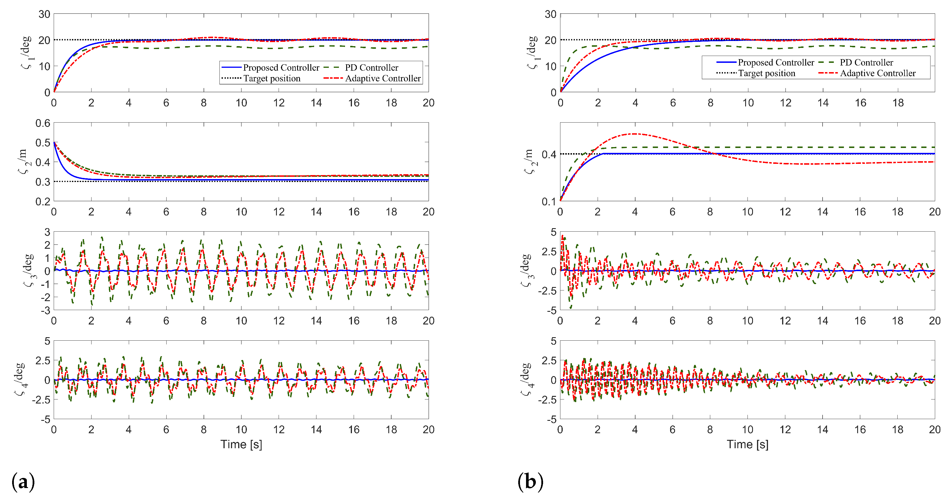
5. Simulation Results and Analysis

To validate the control effectiveness of the proposed controller, we have constructed a dynamic model, as well as the proposed adaptive controller, in the MATLAB/Simulink environment. In the simulation test, the parameters of the crane system are configured as follows:
M = 1.92 kg , m 1 = 0.3 kg , m 2 = 0.5 kg , L j = 0.7 m L 2 = 0.2 m , g = 9 . 8 m / s 2 , ρ = 0.4 sin ( 4.2 t )
Without losing generality, in all simulation tests, the initial value and desired equilibrium point of the states are set as follows:
ζ 1 0 = 0 rad , ζ 2 0 = 0.5 m , ζ 3 0 = 0 rad , ζ 4 0 = 0 rad ζ 1 d = π / 9 rad , ζ 2 d = 0.3 m , ζ 3 d = 0 rad , ζ 4 d = 0 rad
To validate the proposed method, we performed several sets of simulations.
Simulation   Group   1 : We chose the PD control method and the adaptive non-linear anti-swing controller from [40] as the comparison methods for this group of simulation. After careful tuning, the control gains for the PD controller are selected as k 1 d = 80 , k 2 d = 10 , k 1 p = 70 , k 2 p = 15 . Moreover, the non-linear controller is as follows:
f 1 = k p 1 e 1 k d 1 e ˙ 1 Φ 1 T ω ^ 1 Φ 3 T ω ^ 3 f 2 = k p 2 e 2 k d 2 e ˙ 2 Φ 2 T ω ^ 2
And its control gains are
k d 1 = 20 , k d 2 = 30 , k p 1 = 70 , k p 2 = 75
The results of the comparative simulation are shown in Figure 3a. To facilitate interpretation, the units of the angle variable are changed from radians to degrees. As can be seen from Figure 3a, the PD controller and the non-linear controller cannot eliminate positioning errors and do not suppress wave interference. In addition, for the PD controller, the peak angles of the hook and the load are 4.11 deg and 3.04 deg, respectively. Furthermore, there are static errors in the control of the jib and rope length, and the fluctuations exceed 2 deg even after reaching the target position. For the non-linear controller, the peak angles of the hook and the load are 0.96 deg and 3.34 deg, respectively. In contrast, the control method proposed in this paper can accurately reach the target position under continuous wave interference; the peak angles of the hook and the load are 0.12 deg and 0.22 deg, respectively; and the double-pendulum angles can essentially converge to 0, which shows that the control method has good control effects.
To visually illustrate the results, we present a quantitative analysis of the simulation results for the three methods in Table 1, where t 1 and t 2 represent the arrival times of the jib and rope, respectively (the states ζ 1 and ζ 2 for the PD controller, as well as the state variable ζ 2 for the adaptive controller, did not reach or stabilize at the target position, which resulted in the PD controller and the adaptive controller not generating data related to t 1 and t 2 ).
Simulation   Group   2 : To assess the robustness of the proposed controller, we added external interference at T = 10 s on the basis of the second group of simulation, and the simulation results are shown in Figure 3b. When the external interference is added at T = 10 s, the PD control method and the non-linear controller cannot ensure that the swing angle of the hook and the load return to a small range. In contrast, the proposed controller shows good robustness.
Simulation   Group   3 : In this group of simulations, we increased the load mass to 1 kg and compared it with the PD controller and the mentioned non-linear controller. The simulation results are shown in Figure 4a. It can be seen that neither the PD controller nor the non-linear controller is able to eliminate the positioning errors of the actuators. Regarding the pendulum angles of the hook and the load, the peak angle of the load with the PD controller is 2.96 deg, with residual swinging of over 1 deg. The peak load angle with the non-linear controller also is 1.71 deg, and it cannot eliminate positioning errors or suppress wave interference. By contrast, the proposed controller delivers precise positioning performance without any errors. Additionally, it confines the pendulum angles of the hook and load within 0.1 deg. The simulation results demonstrate that the proposed controller maintains good control performance even after increasing the load mass.
Simulation   Group   4 : In this group of simulations, we set the initial and target lengths of the rope to 0.1 m and 0.4 m, respectively, and compared them with the non-linear controller and PD controller. The simulation results are shown in Figure 4b. It can be seen that there is an overshoot of 31.92% in the non-linear controller when the rope length becomes longer. Due to the adaptive term and overshoot limit term, the proposed controller achieves accurate positioning performance without any overshoot. Additionally, the fluctuations in the swing angles of the hook and load under the control of the PD controller and non-linear controller become more severe, with peak values of 4.21 deg, 2.97 deg, 4.49 deg, and 2.54 deg, respectively. In contrast, the proposed controller can suppress the load swing angle to within 0.06 deg. The simulation results demonstrate that the proposed controller maintains good control performance even after changing the target position.

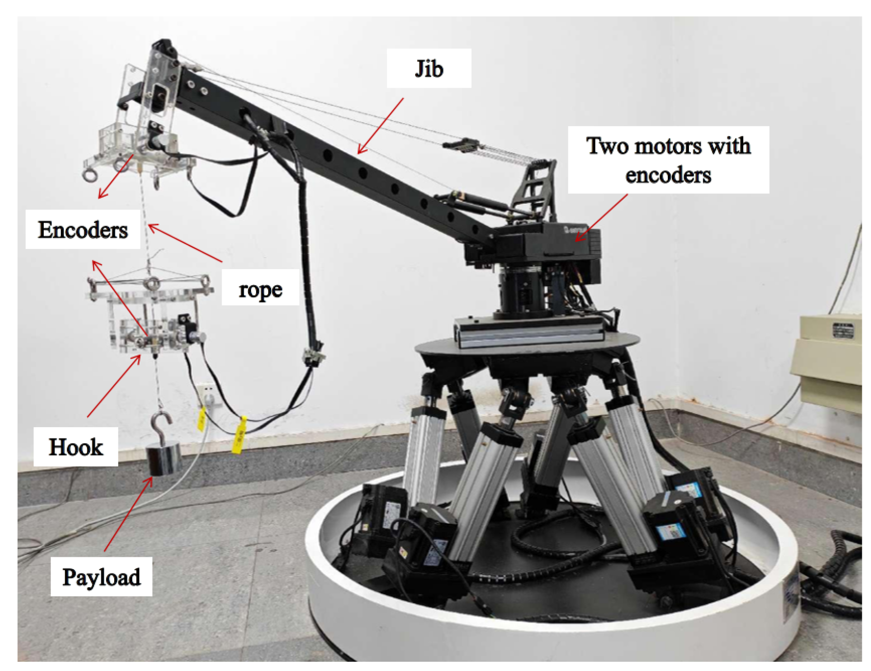
6. Experimental Results and Analysis

To verify the actual control performance of the proposed active disturbance rejection controller, experiments are carried out on the hardware experimental platform of a self-made double-swing crane, and the simulation results are compared. As shown in Figure 5, the device consists of a personal computer, motion control board, encoders, motors, jib, rope, hook, and payload. Two motors are equipped to actuate jib moving and suspension rope variation, respectively. Four encoders are used to measure the jib displacements, suspension rope lengths, and swing angles of the hook and payload, respectively. The physical parameters of the hardware platform are as follows: M = 1.92 kg , m 1 = 0.3 kg ,   m 2 = 0.5 kg ,   L j = 0.7 m ,   L 2 = 0.2 m , g = 9.8 m / s 2 . The initial and target positions are set as ζ 1 0 = 16 deg ,   ζ 2 0 = 0.5 m ,   ζ 3 0 = 0 rad , ζ 4 0 = 0 rad , ζ 1 d = 35 deg , ζ 2 d = 0.3 m , ζ 3 d = 0 rad , ζ 4 d = 0 rad (the parameters are derived from actual measurements of the experimental platform).
The experimental result is shown in Figure 6. It can be seen that the proposed controller can drive the jib and the rope to reach the target position quickly and accurately, and, at the same time, the swing angle of the hook and the load can be suppressed within a small range, in which the peak swing angle of the hook is 1.35 deg, and the residual swing angle is within 0.2 deg. The swing angle of the load is within 0.05 deg. This shows that the controller has a good control effect.

7. Conclusions

In this paper, an active disturbance rejection controller based on an energy coupling method is proposed. The proposed method can guarantee the accurate control of the jib and rope while suppressing the oscillation of the hook and load in the case of continuous wave disturbances and external disturbances. On the theoretical side, the asymptotic stability of the system is demonstrated through the Lyapunov method and LaSalle’s invariance theorem through strict mathematical analysis; from the application perspective, through simulations and experiments, it is proven that the control method has good control performance. In future work, we will consider incorporating the ship’s control issues into the entire control system, aiming to achieve better anti-disturbance performance through the coordinated control of both the ship and the crane.

Author Contributions

Conceptualization, K.Z. and Y.Q.; methodology, K.Z.; software, K.Z. and S.W.; validation, K.Z., S.W. and H.C.; formal analysis, K.Z.; investigation, K.Z.; resources, H.C.; data curation, K.Z.; writing—original draft preparation, K.Z.; writing—review and editing, Y.Q.; visualization, S.W.; supervision, Y.Q.; project administration, Y.Q.; funding acquisition, Y.Q. All authors have read and agreed to the published version of the manuscript.

Funding

This research was funded in part by the Hebei Province Natural Science Foundation (the General Program): F2024202028, the National Natural Science Foundation of China for Youths: 62103128, the Beijing-Tianjin-Hebei Basic Research Cooperation Special Project: F2024202118.

Data Availability Statement

The data presented in this study are available on request from the corresponding author.

Acknowledgments

We thank all the authors for their support. The authors would like to thank all the reviewers who participated in this review.

Conflicts of Interest

The authors declare that they have no known competing financial interests or personal relationships that could have appeared to influence the work reported in this paper.

References

  1. Sun, N.; Liang, X. Nonlinear stable transportation control for double-pendulum shipboard cranes with ship-motion-induced disturbances. IEEE Trans. Ind. Electron. 2019, 66, 9467–9479. [Google Scholar] [CrossRef]
  2. Maghsoudi, M.J.; Mohamed, Z.; Husain, A.R. An optimal performance control scheme for a 3D crane. Mech. Syst. Signal Process. 2016, 66, 756–768. [Google Scholar] [CrossRef]
  3. Stein, A.; Singh, T. Minimum time control of a gantry crane system with rate constraints. Mech. Syst. Signal Process. 2023, 190, 110120. [Google Scholar] [CrossRef]
  4. Rigatos, G. Nonlinear optimal control for the underactuated double-pendulum overhead crane. J. Vib. Eng. Technol. 2024, 12, 1203–1223. [Google Scholar] [CrossRef]
  5. Zhong, K.; Qian, Y. Time-optimal anti-swing trajectory planning of double pendulum crane based on chebyshev pseudo-spectrum method. In Proceedings of the International Conference on Applied Nonlinear Dynamics, Vibration and Control, Hong Kong, China, 4–6 December 2023; Springer Nature: Singapore, 2023; pp. 541–553. [Google Scholar]
  6. Cong, Y.; Li, G.; Li, J.; Tian, J.; Ma, X. Time-delay-based sliding mode tracking control for cooperative dual marine lifting system subject to sea wave disturbances. Actuators 2024, 13, 491. [Google Scholar] [CrossRef]
  7. Chen, H.; Tang, S.; Han, J. High-order sliding mode control of a doubly salient permanent magnet machine driving marine current turbine. J. Ocean Eng. Sci. 2021, 6, 12–20. [Google Scholar] [CrossRef]
  8. Wu, S.; Zhang, H.; Qian, Y. Reinforcement Learning Strategy-Based Adaptive Tracking Control for Underactuated Dual Ship-Mounted Cranes: Theoretical Design and Hardware Experiments. IEEE Trans. Ind. Electron. 2024; Early Access. [Google Scholar] [CrossRef]
  9. ur Rehman, S.M.F.; Mohamed, Z.; Husain, A.R. Input shaping with an adaptive scheme for swing control of an underactuated tower crane under payload hoisting and mass variations. Mech. Syst. Signal Process. 2022, 175, 109106. [Google Scholar] [CrossRef]
  10. Zhao, W.; Ebbesen, M.; Hansen, M.; Andersen, T. Experimental verification of a two-motor-two-pump motor-controlled hydraulic cylinder with throttle-free passive load-holding capability in four-quadrant operations. Actuators 2024, 13, 372. [Google Scholar] [CrossRef]
  11. Wu, Q.; Sun, N.; Wang, X. Equivalent rope length-based trajectory planning for double pendulum bridge cranes with distributed mass payloads. Actuators 2022, 11, 25. [Google Scholar] [CrossRef]
  12. Zhang, G.; Li, J.; Chang, T. Autonomous navigation and control for a sustainable vessel: A wind-assisted strategy. Sustain. Horizons 2025, 13, 100117. [Google Scholar] [CrossRef]
  13. Zhang, C.; Guo, G. Prescribed performance fault-tolerant control of nonlinear systems via actuator switching. IEEE Trans. Fuzzy Syst. 2023, 32, 1013–1022. [Google Scholar] [CrossRef]
  14. Li, L.; Amer, A.; Zhu, X. Numerical analysis of an over-boarding operation for a subsea template. J. Ocean Eng. Sci. 2021, 6, 146–159. [Google Scholar] [CrossRef]
  15. Zhao, B.; Ouyang, H.; Iwasaki, M. Motion trajectory tracking and sway reduction for double-pendulum overhead cranes using improved adaptive control without velocity feedback. IEEE/ASME Trans. Mechatronics 2021, 27, 3648–3659. [Google Scholar] [CrossRef]
  16. Li, J.; Zhang, G.; Cabecinhas, D. Prescribed performance path following control of USVs via an output-based threshold rule. IEEE Trans. Veh. Technol. 2023, 73, 6171–6182. [Google Scholar] [CrossRef]
  17. Ouyang, H.; Xu, X.; Zhang, G. Energy-shaping-based nonlinear controller design for rotary cranes with double-pendulum effect considering actuator saturation. Autom. Constr. 2020, 111, 103054. [Google Scholar] [CrossRef]
  18. Sun, Z.; Ouyang, H. Adaptive fuzzy tracking control for vibration suppression of tower crane with distributed payload mass. Autom. Constr. 2022, 142, 104521. [Google Scholar] [CrossRef]
  19. Shi, H.; Huang, J.; Bai, X. Nonlinear anti-swing control of underactuated tower crane based on improved energy function. Int. J. Control Autom. Syst. 2021, 19, 3967–3982. [Google Scholar] [CrossRef]
  20. Li, G.; Ma, X.; Li, Y. Adaptive anti-swing control for 7-DOF overhead crane with double spherical pendulum and varying cable length. IEEE Trans. Autom. Sci. Eng. 2023, 21, 5240–5251. [Google Scholar] [CrossRef]
  21. Qiang, H.; Sun, Y.; Lyu, J. Anti-sway and positioning adaptive control of a double-pendulum effect crane system with neural network compensation. Front. Robot. AI 2021, 8, 639734. [Google Scholar] [CrossRef] [PubMed]
  22. Ren, Z.; Verma, A.; Ataei, B. Model-free anti-swing control of complex-shaped payload with offshore floating cranes and a large number of lift wires. Ocean Eng. 2021, 228, 108868. [Google Scholar] [CrossRef]
  23. Zhao, T.; Sun, M.; Wang, S. Dynamic analysis and robust control of ship-mounted crane with multi-cable anti-swing system. Ocean Eng. 2024, 291, 116376. [Google Scholar] [CrossRef]
  24. Wu, Y.; Sun, N.; Chen, H. New adaptive dynamic output feedback control of double-pendulum ship-mounted cranes with accurate gravitational compensation and constrained inputs. IEEE Trans. Ind. Electron. 2021, 69, 9196–9205. [Google Scholar] [CrossRef]
  25. Qiang, H.; Xie, S.; Xu, Z. An enhanced sliding mode control method for wave compensation system of ship-mounted cranes with roll motions and parametric uncertainties. J. Mar. Sci. Technol. 2020, 28, 6. [Google Scholar]
  26. Yang, T.; Sun, N.; Chen, H. Neural network-based adaptive antiswing control of an underactuated ship-mounted crane with roll motions and input dead zones. IEEE Trans. Neural Netw. Learn. Syst. 2019, 31, 901–914. [Google Scholar] [CrossRef]
  27. Kuchler, S.; Mahl, T.; Neupert, J. Active control for an offshore crane using prediction of the vessel’s motion. IEEE/ASME Trans. Mechatronics 2010, 16, 297–309. [Google Scholar] [CrossRef]
  28. Guo, B.; Chen, Y. Fuzzy robust fault-tolerant control for offshore ship-mounted crane system. Inf. Sci. 2020, 526, 119–132. [Google Scholar] [CrossRef]
  29. Li, G.; Ma, X.; Li, Y. Robust Command Shaped Vibration Control for Stacker Crane Subject to Parameter Uncertainties and External Disturbances. IEEE Trans. Ind. Electron. 2024, 71, 14740–14752. [Google Scholar] [CrossRef]
  30. Wang, Y.; Yang, T.; Zhai, M. Ship-Mounted Cranes Hoisting Underwater Payloads: Transportation Control with Guaranteed Constraints on Overshoots and Swing. IEEE Trans. Ind. Inform. 2023, 19, 9968–9978. [Google Scholar] [CrossRef]
  31. Zhang, Y.; Shen, W.; Long, Z. Active pendulation control of hoisting systems of ship-mounted cranes under ocean wave excitations: Principle and experimental study. Mech. Syst. Signal Process. 2025, 222, 111802. [Google Scholar] [CrossRef]
  32. Kim, T.; Nguyen, L.; Dinh, X. Adaptive hierarchical sliding mode control design for 3D ship-mounted container crane with saturating actuators. J. Control. Autom. Electr. Syst. 2022, 33, 1643–1658. [Google Scholar] [CrossRef]
  33. Hu, D.; Qian, Y.; Fang, Y. Modeling and nonlinear energy-based anti-swing control of underactuated dual ship-mounted crane systems. Nonlinear Dyn. 2021, 106, 323–338. [Google Scholar] [CrossRef]
  34. Wang, F.; Li, G.; Jiang, W. Collaborative heave compensation control of dual ship-mounted lifting arm system based on incremental model predictive control. In Proceedings of the 2024 14th Asian Control Conference (ASCC), Dalian, China, 5–8 July 2024; pp. 1–6. [Google Scholar]
  35. Li, G.; Ma, X.; Li, Z. Energy Shaping Based Nonlinear Anti-Swing Controller for Double-Pendulum Rotary Crane with Distributed-Mass Beams. In Proceedings of the 2022 IEEE International Conference on Real-time Computing and Robotics (RCAR), Guiyang, China, 17–22 July 2022; pp. 207–212. [Google Scholar]
  36. Kim, D.; Park, Y. Tracking control in xy plane of an offshore container crane. J. Vib. Control 2017, 23, 469–483. [Google Scholar] [CrossRef]
  37. Chen, S.; Xie, P.; Liao, J. Cascade NMPC-PID control strategy of active heave compensation system for ship-mounted offshore crane. Ocean Eng. 2024, 302, 117648. [Google Scholar] [CrossRef]
  38. Bozkurt, B.; Ertogan, M. Heave and horizontal displacement and anti-sway control of payload during ship-to-ship load transfer with an offshore crane on very rough sea conditions. Ocean Eng. 2023, 267, 113309. [Google Scholar] [CrossRef]
  39. Bae, J.; Cha, J. Heave reduction of payload through crane control based on deep reinforcement learning using dual offshore cranes. J. Comput. Des. Eng. 2023, 10, 414–424. [Google Scholar] [CrossRef]
  40. Zhang, H.; Qian, Y. Adaptive nonlinear antiswing control for underactuated dual ship-Mounted cranes with sea wave cisturbances. In Proceedings of the IEEE 2023 42nd Chinese Control Conference (CCC), Tianjin, China, 24–26 July 2023; pp. 338–343. [Google Scholar]
Figure 1. Schematic diagram of double-pendulum ship-borne crane.
Actuators 14 00052 g001
Figure 2. Flowchart of the overall control system.
Actuators 14 00052 g002
Figure 3. The results of Group 1 and Group 2. (a) The results of Group 1: comparison simulation with PD controller and non-linear controller (blue solid line: the proposed controller; red dotted line: the adaptive controller; green dashed line: the PD controller). (b) The results of Group 2: adding external interference (blue solid line: the proposed controller; red dotted line: the adaptive controller; green dashed line: the PD controller). The interference is added at T = 10 s.
Actuators 14 00052 g003
Figure 4. The results of Group 3 and Group 4. (a) The results of Group 3: increasing the load mass to 1 kg (blue solid line: the proposed controller; red dotted line: the adaptive controller; green dashed line: the PD controller). (b) The results of Group 4: changing the initial and target length of the rope to 0.1 m and 0.4 m, respectively (blue solid line: the proposed controller; red dotted line: the adaptive controller; green dashed line: the PD controller).
Actuators 14 00052 g004
Figure 5. Self-built double-pendulum crane platform.
Actuators 14 00052 g005
Figure 6. The comparison between the experimental results and simulation results (blue solid line: experimental result; red dotted line: simulation result).
Actuators 14 00052 g006
Table 1. Quantified analysis results.
Control Method t 1 / s t 2 / s e 1 / deg
Proposed controller10.782.210
PD controller//0.43
Adaptive controller8.84/0.80
e 2 / m ζ 3 max / deg ζ 4 max / deg
Proposed controller0.0060.120.22
PD controller0.0304.113.04
Adaptive controller0.0430.963.34
Disclaimer/Publisher’s Note: The statements, opinions and data contained in all publications are solely those of the individual author(s) and contributor(s) and not of MDPI and/or the editor(s). MDPI and/or the editor(s) disclaim responsibility for any injury to people or property resulting from any ideas, methods, instructions or products referred to in the content.

