Article

The Design and Analysis of a Lightweight Robotic Arm Based on a Load-Adaptive Hoisting Mechanism

by
Ruchao Wang
,
Zhiguo Lu
*,
Yiru Wang
and
Zhongqing Li
School of Mechanical Engineering and Automation, Northeastern University, Shenyang 110819, China
*
Author to whom correspondence should be addressed.
Actuators 2025, 14(2), 71; https://doi.org/10.3390/act14020071
Submission received: 30 December 2024 / Revised: 1 February 2025 / Accepted: 3 February 2025 / Published: 5 February 2025

Abstract

:
This paper presents the design and control of a lightweight three degrees of freedom robotic arm based on a load-adaptive hoisting mechanism. The proposed design integrates a spring-loaded rope and a variable radius reel into the gripper, enabling efficient load adaptability with minimal structural complexity. By leveraging this mechanism, the robotic arm achieves significant weight reduction while maintaining robust performance under variable payloads. The study includes a comprehensive analysis of the system’s kinematics and dynamics, focusing on the interaction between the adaptive gripper and the arm structure. A prototype of the robotic arm was developed and experimentally tested to validate its functionality.

1. Introduction

Humans have long envisioned robots performing increasingly complex and dynamic tasks in harsh and demanding environments. This creates an urgent demand for a versatile, intelligent, and simplified robotic arm and gripper capable of adapting to various challenging environmental conditions and collaborating with robots to complete precise and complex tasks [1,2]. The combination of point-foot biped robots [3,4] with robotic arms significantly enriches the variety of tasks they can undertake, enhancing their versatility. However, considering the structural characteristics and control methods of point-foot biped robots, there is a need for robotic arms and gripping mechanisms that are lightweight, exert minimal impact on the robot’s mobility platform, and demonstrate superior motion characteristics [5].
To address this demand, this paper introduces a novel robotic arm design featuring a cable-driven gripper, based on a load-adaptive hoisting mechanism [6]. The study analyzes and experiments on the motion characteristics of the gripper when integrated with the robotic arm. In the development of robotic arms with grippers, key areas for further exploration include lightweight design and the gripper’s ability to quickly and actively adapt to target objects [7].
Due to technological advancement, gripper-equipped robots can now perform many tasks traditionally associated with human hands. However, many challenges remain, such as difficulties in force control when handling fragile objects and the limited flexibility of conventional gripper designs [8]. These issues highlight the necessity of innovative approaches to gripper design and functionality.
In recent decades, the development of flexible grippers has advanced significantly, driven primarily by the growing demand for industrial automation, service robots, and precise tasks in constrained environments [8]. The design of lightweight actuators with variable transmission ratios [9,10] and grippers that actively adapt their shape to match the contours of objects [11] have become key focus areas. These innovations directly influence the energy efficiency, load capacity, and overall adaptability of robotic systems.
For example, deformable single-mass grippers have shown promising adaptability to various object shapes. This is evident in the prestressed soft gripper designed for food handling [7], the origami-inspired reconfigurable suction gripper [12], the multi-legged gripper [9], and the flat adhesive soft gripper [9], all of which exhibit capabilities for handling objects of different shapes to varying degrees. Similarly, some grippers based on underconstrained mechanisms, such as the compliant adaptive gripper described in [13], also demonstrate shape adaptability, enhancing their versatility in diverse applications.
In the field of robotic microactuators, many researchers have proposed excellent designs for continuously variable transmissions (CVTs) and conducted in-depth studies. For instance, the application of torsional string actuators (TSA) enables variable transmission ratios in robotic fingers or smaller components. By controlling different motor drive modes, it is possible to efficiently switch between high-speed and high-tension modes [14,15,16,17].
To achieve smooth and adjustable transmission ratios, some mechanisms utilize electrostatic hybrid actuators, where hydraulic systems drive connected linkages to modify the output reduction ratio [18,19]. Another type of mechanism, based on TSA or screw mechanisms, adjusts its transmission ratio dynamically according to load variations [20,21,22,23]. These mechanisms are often deployed in specialized robotic joints, featuring regular patterns of transmission ratio variation depending on connection characteristics [24,25,26,27].
Additionally, traditional CVT technologies from the automotive industry have been adapted for robotic joints, resulting in more compact and modular designs [28]. Inspired by bionics, researchers have optimized the positioning of joint actuators to enable changes in transmission ratios [29]. A novel concept involving non-contact variable transmission mechanisms has also been proposed, utilizing coaxial magnetic gears [30], representing an intriguing new direction.
To achieve adaptive and continuous variation in the transmission ratio based on load changes, this paper proposes a robotic arm utilizing a load-adaptive variable transmission mechanism that combines high-speed motion with significant gripping force. The mechanism converts the rotational motion of a motor into linear motion through a variable-radius reel and load-adaptive spring within a load-adaptive hoisting device.
The adaptive transmission ratio adjusts smoothly and continuously under different load conditions. When the robotic gripper is unloaded, the load-adaptive transmission mechanism operates in a high transmission ratio state, enabling the robotic fingers to move at high speed with low gripping force. Conversely, when the robotic fingers make contact with an object, the mechanism transitions to a low transmission ratio state, allowing the fingers to operate at low speed with high gripping force. This mechanism enables seamless, passive transitions between high and low transmission ratios without requiring sensors to detect gripping force.
This paper presents the design of a lightweight, three degrees of freedom robotic arm, which integrates a load-adaptive hoisting mechanism into its gripper. The mechanism, based on a spring-loaded rope and variable-radius reel, was introduced in our previous research and enables efficient load handling with minimal structural and computational complexity. The integration of this mechanism ensures a lightweight structure suitable for a wide range of applications while maintaining adaptability.
The main contributions of this study are as follows: (1) The development of an innovative three degrees of freedom lightweight robotic arm with an integrated gripper mechanism, as shown in Figure 1. (2) The smooth force control and precise position control of the end-effector gripper, leveraging sensor data and the structural mechanical characteristics. A detailed view of the gripper is provided in Figure 2 and Figure 3. (3) Experimental validation of the proposed mechanism’s performance and characteristics by conducting grasping tests on objects with varying stiffness.
The remainder of this paper is structured as follows: Section 2 introduces the design principles and features of the mechanism. Section 3 covers the dynamic analysis of the robotic arm. Section 4 describes the experimental validation. Section 5 and Section 6 present the discussion and conclusions, respectively.

2. Design Principles and Characteristics of the Mechanism

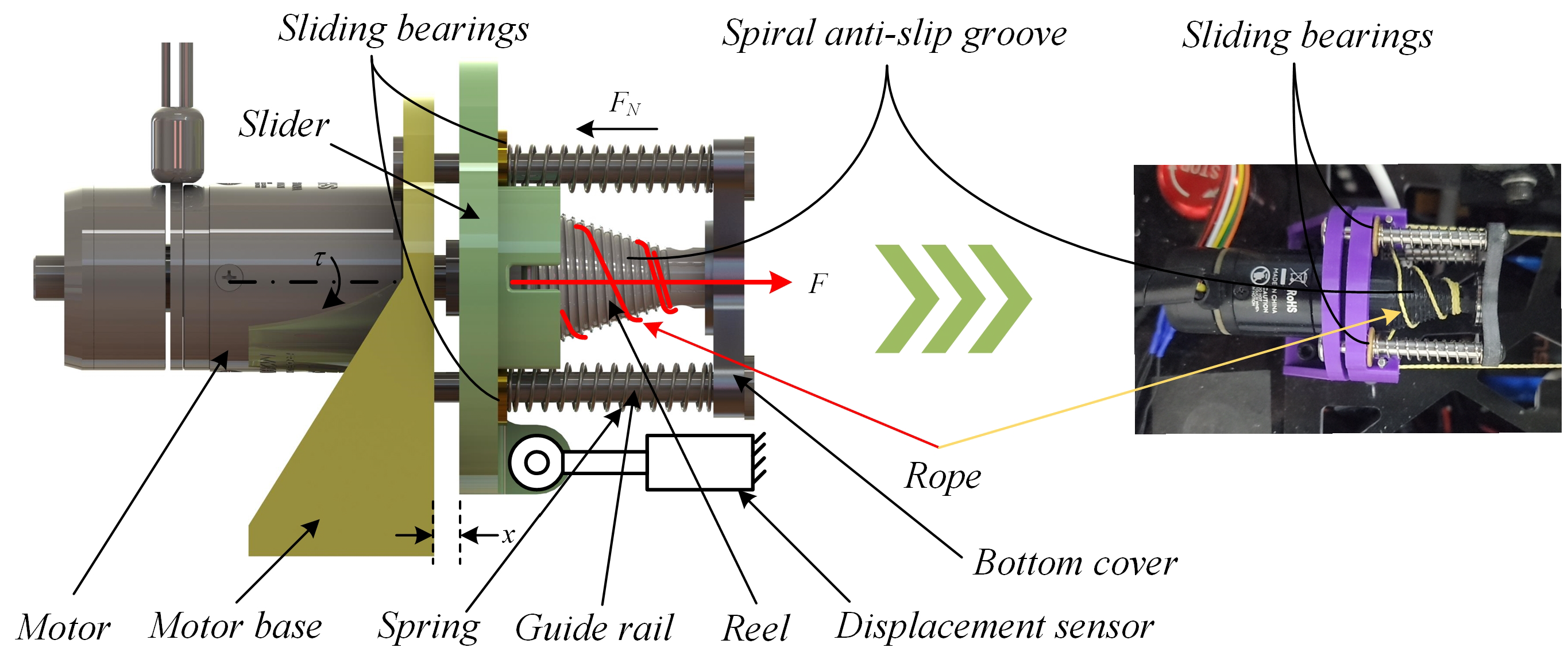
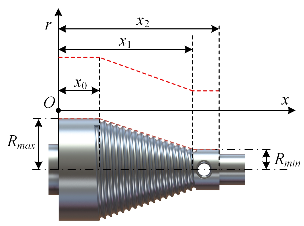
2.1. Improved Load-Adaptive Hoisting Mechanism

The load-adaptive hoisting mechanism is mainly composed of a motor, a displacement sensor, a motor base, a variable radius reel, four guide rails, four springs, a slider, a rope, and a bottom cover, as shown in Figure 2. The motor is fixed on the motor base, the reel is connected with the output shaft of the motor, and the sliders slide along the guide rails. The rope passes through the reel at first and then it passes through the rope winding shaft through the slider; next, it passes through the hole on the bottom cover and then it is fixed to the external load. Finally, bolts are used to secure the motor base to a black board as shown in Figure 3. The springs are sleeved on the guide rails and placed between the slider and the bottom cover.
The improved load-adaptive hoisting mechanism is shown in Figure 2. Compared to the previous version of the mechanism [6], both the reel and the slider have been significantly improved.
First, the reel now features a spiral anti-slip groove design to enhance the efficiency of the rope winding process and reduce the possible of slippage. Subsequent experiments will further demonstrate its superior performance compared to earlier versions. To minimize resistance and friction caused by the slider’s movement, four self-lubricating sliding bearings have been installed on the slider. In addition, the position sensor mounted between the base and the slider can precisely detect the displacement of the slider, allowing for the indirect monitoring of the current force exerted by the end-effector gripper.
Figure 2. Schematic diagram of the improved load-adaptive hoisting mechanism.
Actuators 14 00071 g002
Figure 3. Schematic diagram of the lightweight robotic arm structure design.
Actuators 14 00071 g003

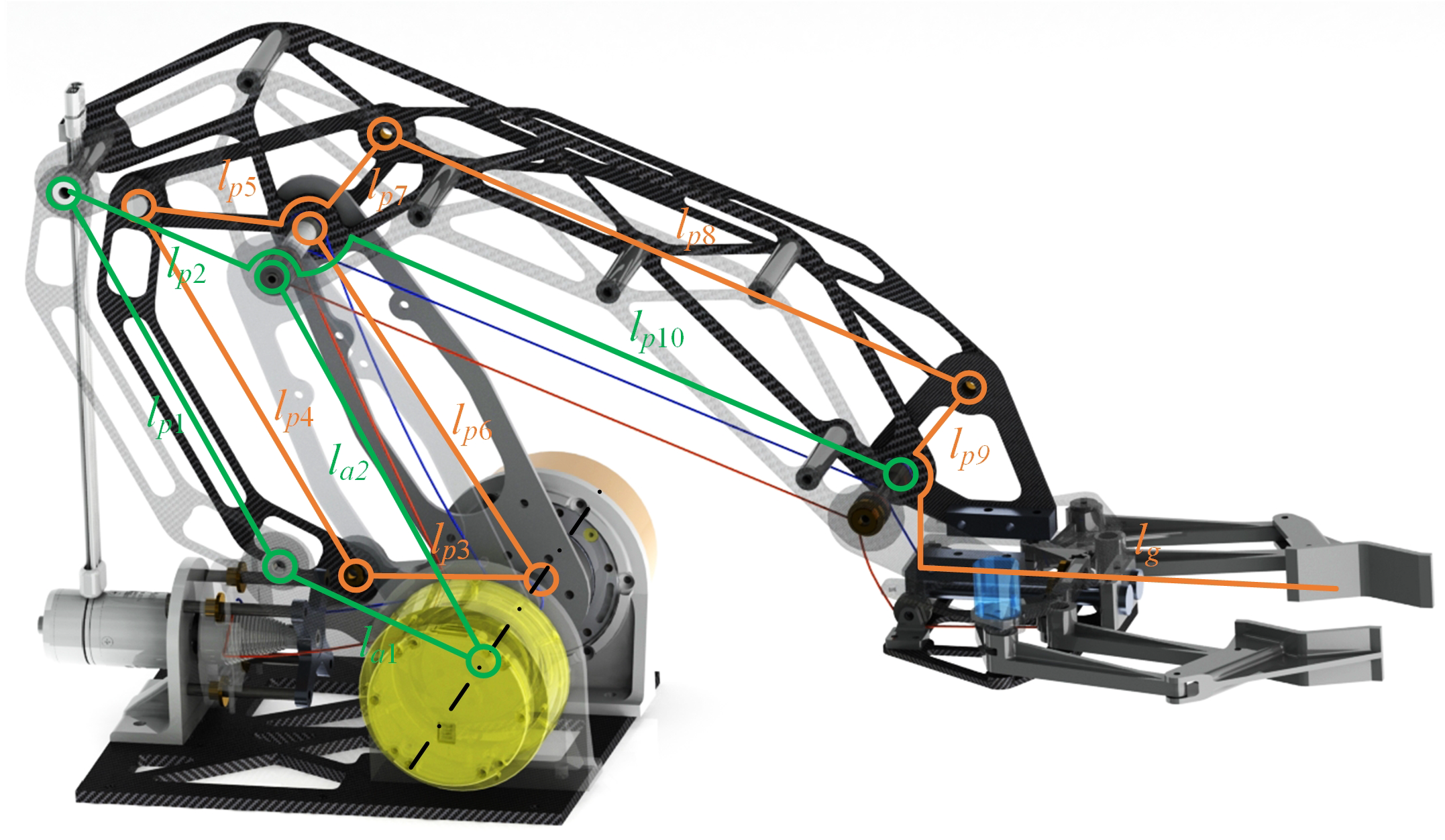
2.2. Robotic Arm Structure

The robotic arm structure draws inspiration from the design of palletizing robots [31]. To achieve a lightweight design, the primary materials used include carbon fiber plates and PLC-printed components. The weight of the robotic arm is primarily concentrated at the base, and the torque generated by the joint motors is transmitted through multiple connecting links. A schematic diagram of the structure is shown in Figure 3 from the perspective of the side view of the robotic arm; linkages l a 1 and l a 2 are the driving linkages, with joint motors driving their rotation. Linkages l p 1 , l p 2 , l p 3 , and l p 4 are passive linkages, which move passively through hinged connections.
The designed robotic arm features a lightweight end-effector, with a compact retracted size, and the retracted arm adopts a “Z” shape. The arm consists of three sets of parallel linkage mechanisms: the first pair of combined linkages are l a 1 , l a 2 , l p 1 , and l p 2 ; the second set of parallel linkages includes l p 3 , l p 4 , l p 5 , and l p 6 ; the third set of parallel linkages consists of l p 7 , l p 8 , l p 9 , and l p 10 . The combination of these three sets of parallel linkages ensures that linkage l g remains parallel to the base at all times. Since linkages l p 5 and l p 7 are fixed together, the angle of linkage l p 3 remains unchanged during the arm’s movement. Furthermore, because the gripper is hinged to linkage l p 9 , the structure guarantees that the gripper always stays horizontal relative to the base.

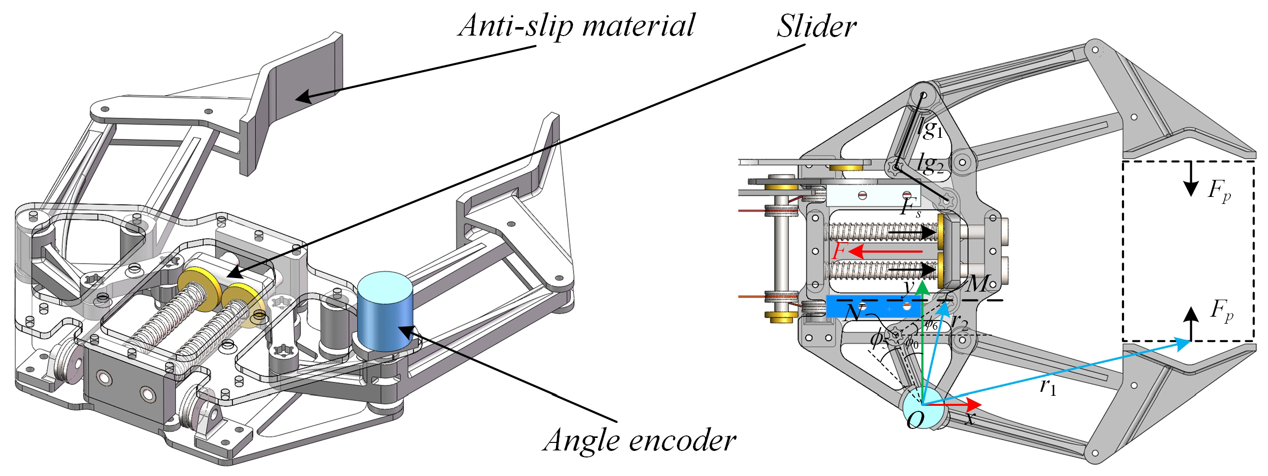
2.3. Gripper Structure

The schematic diagram of the gripper’s structure is shown in Figure 4. It uses a parallel linkage structure, with the active joints sliding along a guide rail to achieve the opening and closing of the gripper. Additionally, an angle sensor is installed at the gripper to accurately measure its opening angle ϕ 5 . This, combined with the load-adaptive hoisting mechanism, enables the precise force-position control of the gripper.
The entire gripper is designed with a lightweight structure, utilizing a significant amount of carbon fiber plates and PLC materials. The weight of the gripper is shown in Table 1. Anti-slip material is applied to the inner surface of the gripper to improve its ability to grasp objects. The rope is fixedly connected to the slider, providing the gripping force F, while the opening force is provided by the spring force F s installed on the rail.

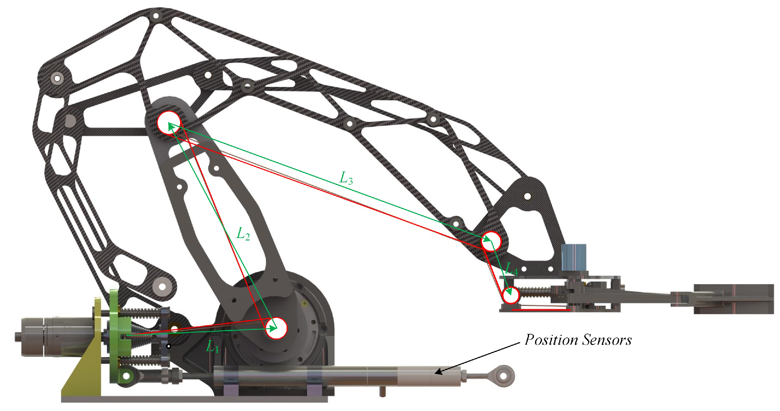
2.4. Constant Line Length
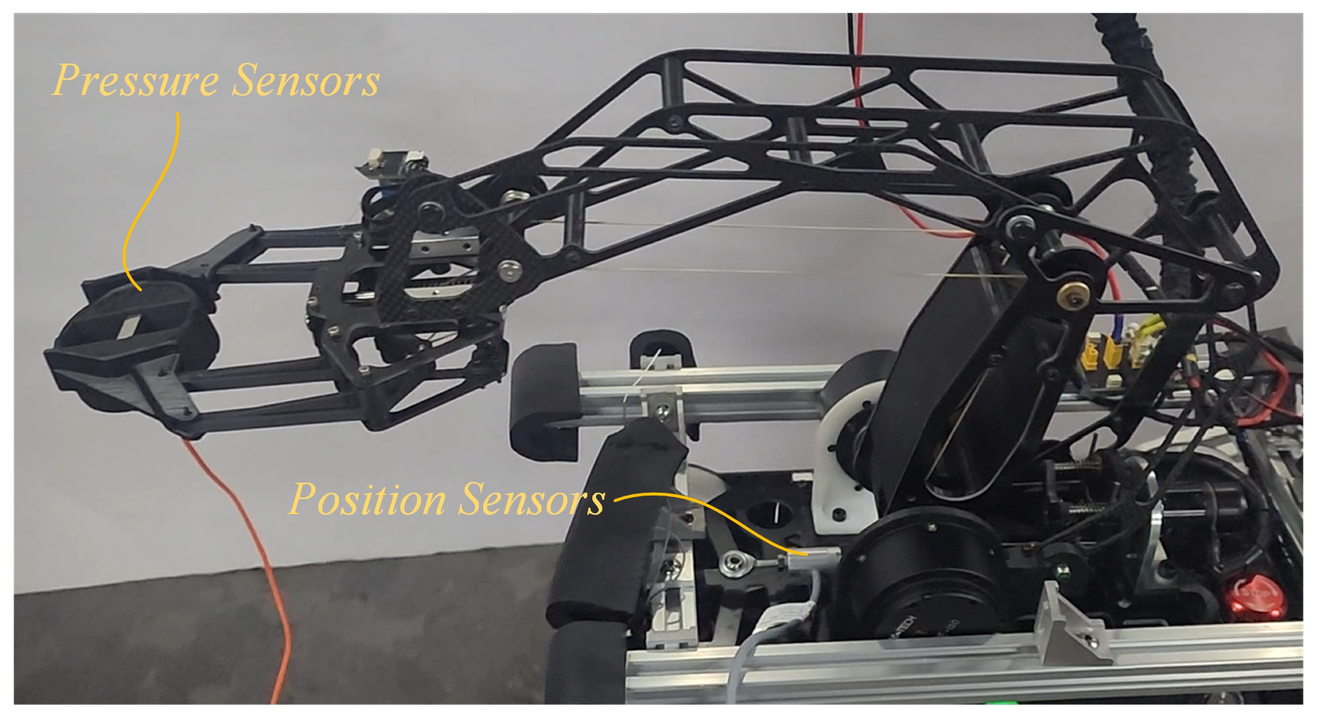
The driving force of the manipulator is transmitted through the rope as shown in Figure 5, and the arrangement of the rope is crucial for the opening and closing action of the manipulator. The rope is wound as shown in the red solid line, and the Euclidean parameter of the vector at each winding point (shown in the green solid line) is constant. This ensures that the opening and closing action of the gripper is not affected regardless of the movement of the robotic arm.

2.5. Sensor Layout

The position sensor of the robotic arm is arranged above the motor base, as shown in Figure 5. It is used to check the position of the slider. According to the characteristics of the load-adaptive mechanism, the position of the slider is directly proportional to the gripping force of the gripper. Therefore, by detecting the position of the slider, the gripping force at the end gripper can be clearly determined. To better control the gripper and achieve flexible grasping, a angle sensor is also installed at the gripper, allowing for the accurate measurement of the gripper’s state.

3. Kinematic Analysis of the Robotic Arm

The robotic arm based on the load-adaptive hoisting mechanism has distinct differences compared to other robotic arms, as mentioned in the previous background section. In the following section, we will conduct a theoretical analysis to explore these specific motion features.

3.1. Motion Characteristics of the Improved Load-Adaptive Hoisting Mechanism

The schematic diagram of the improved hoisting mechanism and the reel are shown in Figure 2 and Figure 6. The expression for the radius of the reel r corresponding to the position of the slider at different positions is given by
r = R max , x 0 , l 0 R max R min l 1 l 0 x + R max , x l 0 , l 1 R min , x l 1 , l 2
For the load-adaptive hoisting mechanism, see Figure 2. For different load forces F, the expression of its slider push line at the radius r of the reel is
r = R max R min F 2 k l 1 l 0 + R max F τ R max , τ R min
where τ represents the torque provided by the motor, k is the stiffness coefficient of the spring, and the selected spring satisfies Hooke’s law. Within its range of motion, x = 0.25 F/k.
For the load-adaptive hoisting mechanism, the pulling speed v of the line rope is expressed as follows
v = ω R max , F 0 , τ R max ω R min , F 0 , τ R min ω R max R min F 2 k l 1 l 0 + ω R max , F τ R max , τ R min
where ω is the angular velocity of the motor. When the slider pushes the rope at the radius R max of the reel, it is in high speed mode. When the slider pushes the rope at radius R min of the reel, it is in high load mode. When the slider pushes the rope between the radius R min and R max of the reel, it is in the adaptive mode.
The relationship between the output torque τ and the load force F is essentially unchanged in the coarse and fine reels, both providing the maximum torque on their own, but expressed as follows in the variable radius configuration:
τ = 4 r F N = R max R min F 2 2 k l 1 l 0 + R max F , F τ R max , τ R min

3.2. Analysis of the Robotic Arm’s Motion Characteristics

The innovative robotic arm based on the load-adaptive hoisting mechanism (LAHM) utilizes a two degrees of freedom (2-DOF) design in its structure. This configuration enhances the arm’s adaptability and precision, especially in tasks requiring dynamic force control and flexibility.

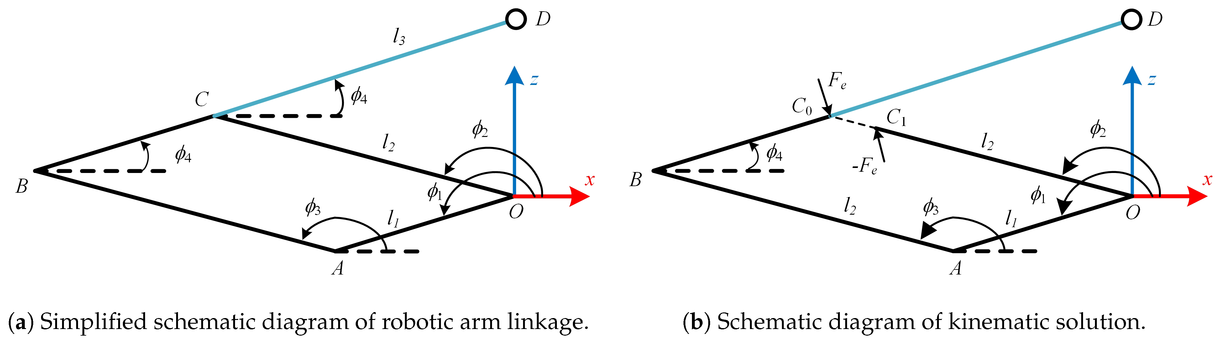
3.2.1. Kinematic Analysis

The main feature of the mechanism is that it references the structure of industrial palletizing robots, which do not have a rotating base joint but instead feature only two degrees of freedom. Given the known position of the end effector (gripper), the relationship equation can be constructed using vector methods:
O A + A B + B C = O C O A + A B + B C + C D = O C + C D
where the vector expression is shown in Figure 7a. By using the half-angle trigonometric relationship, the angle expression for ϕ 4 can be solved as
ϕ 4 = 2 a t a n 2 B a + A a 2 + B a 2 C a 2 A a + C a
where
A a = 2 ( x d ) l 3 B a = 2 ( y d ) l 3 C a = ( x d ) 2 ( y d ) 2 l 2 2 + l 3 2
By solving for the angle ϕ 4 , the position of point C can be indirectly determined, and thus, the angle expression for ϕ 1 can be obtained as
ϕ 1 = 2 a t a n 2 B b + A b 2 + B b 2 C b 2 A b + C b
where
x D d = x d ( l 1 + l 3 ) c o s ( ϕ 4 ) y D d = y d ( l 1 + l 3 ) s i n ( ϕ 4 ) A b = 2 ( x D d ) l 1 B b = 2 ( y D d ) l 1 C b = ( x D d ) 2 ( y D d ) 2 l 2 2 + l 3 2
during the motion solution, the mechanical limit makes the graph formed by point C convex, so the positive sign is used after parameter B a ( B b ) in Equations (6) and (8). Because of the mechanical limit, the minimum angle of the linkage l 2 is guaranteed to be 0.524 rad, and there is no singular position of the robotic arm within such a range of motion. Currently the farthest reach of the robotic claw from the base is 0.32 m, and the maximum height is 0.15 m.
Similarly, using the same method, the angle ϕ 2 can be obtained. The distance between the position and the gripper center remains constant. If the goal is to further determine the joint angles based on a given gripper position, one simply needs to add a 2D constant c to position D and then use the above method to calculate the joint positions. Similarly, given the angles of the active joints and using vector methods, the forward kinematic expressions for the joints can be derived through half-angle functions. This allows for the calculation of the Jacobian matrix using differential methods, which will aid in the subsequent dynamics analysis.

3.2.2. Dynamics Analysis

The Lagrangian dynamics approach is used to solve the problem, and the mechanical relationship expression is given by
M q ( θ ) θ ¨ + C a ( θ , θ ˙ ) + G a ( θ ) = J T F e + τ e
The expressions M q ( θ ) , C a ( θ , θ ˙ ) , and G a ( θ ) represent the mass matrix of the entire system, the Coriolis and centrifugal force terms, and the gravitational force terms, respectively. Here, J is the Jacobian matrix of the system, F e is the force exerted by the gripper, which corresponds to the mass of the object being grasped, and τ e is the torque output at the joints. The weights and dimensions of the links are provided in Table 1.
For the parallel mechanism, the point C in Figure 7 will be treated as split, and the separated points will be subjected to equal and opposite forces, which will be reconstructed with the following dynamic equations
M t ( q ) q ¨ + C b ( q , q ˙ ) + G b ( q ) = J P C 0 T F e + J P C 1 T ( F e )
where q = ϕ 1 ϕ 2 ϕ 3 ϕ 4 T , and as shown in Figure 7b, points C 0 and C 1 are combined, so the information about their small changes in position and speed is the same. There is the following relation equation
δ P C 0 = δ P C 1
where δ P represents the small movement of the foot tip position in positional space; mapping the robot pose space to the joint space helps us to obtain
J P C 0 q ˙ = J P C 1 q ˙
Further differential calculations were performed to obtain
J P 2 q ¨ + J ˙ P 2 q ˙ = J P 4 q ¨ + J ˙ P 4 q ˙
Combining Equation (11) and Equation (14) yields the following matrix equation
M t ( q ) J c T J c 0 q ¨ F e = C b ( q , q ˙ ) G b ( q ) J ˙ c q ˙
where J c = J P C 0 J P C 1 , the leftmost matrix of the above equation is A, and the above equation is abbreviated as follows:
A 11 θ ¨ + A 12 φ ¨ = b 1 A 21 θ ¨ + A 22 φ ¨ = b 2
where θ = [ ϕ 1 , ϕ 2 ] T , φ = [ ϕ 3 , ϕ 4 , F e x , F e z ] T , and A i i , b i , i = 1, 2 are the coefficient matrices corresponding to the simplified equations. And the above system of equations, eliminating the variable φ , yields
A ˜ θ ¨ = b ˜ A ˜ = A 11 A 12 A 22 1 A 21 b ˜ = b 1 A 12 A 22 1 b 2
By combining feedback information from joint angle and angular velocity, feedback control methods can be used to obtain joint torque τ = τ 1 , τ 2 T , as shown in the following equation
τ = A ˜ θ ¨ r e f + k p θ r e f θ f b + k d θ ˙ r e f θ ˙ f b b ˜
where k p and k d are proportional and differential coefficients, and θ r e f and θ f b represent the set and feedback values of the joint angles, respectively. By solving the kinematic solution and dynamics of the robotic arm in forward and reverse kinematics, the robotic arm is finally controlled with a predetermined trajectory using the PD control method, in which the control flow chart is shown in Figure 8.

3.2.3. Gripper Force Analysis

The rope driven gripper adopts a parallel mechanism, and its force analysis diagram is shown in Figure 4. In the mechanical analysis, the gripping force F p of the hand gripper has the following relational expression
r 2 × F F s = r 1 × F p
where F and F s represent the tension force of the load-adaptive hoisting mechanism and the spring restoring force at the gripper, and r 1 and r 2 represent the vectors in the coordinate system shown in the figure, respectively. The position sensor installed at the gripper obtains the current angle of the gripper ϕ 5 and the initial angle of the hand gripper is known as ϕ 0 ; the spring force at the gripper can be solved for
F s = k M x c o n M x
where k denotes the elasticity coefficient of the spring, and M x c o n and M x denote the initial coordinates of the x axis of the point M under the coordinate system of the point O and the coordinates of the point M after moving, respectively. Where the coordinates of the point N are expressed as follows
N y = l g 1 sin ϕ 5 + ϕ 0 N x = l g 1 cos ϕ 5 + ϕ 0
Finally, by solving the joint additivity ϕ 6 , the moving coordinate M x of point M is obtained
M y = N y + l g 2 sin ϕ 6 M x = N x + l g 2 cos ϕ 6

4. Experimental Validation

In this study, a series of experiments are carefully designed and implemented in order to deeply explore the motion characteristics of the robotic arm designed based on the load-adaptive hoisting mechanism and to verify the theoretical analysis and hypotheses previously discussed. The experimental part is one of the core contents of this paper, aiming to empirically test the validity of the model, the performance of the algorithm or the existence of certain phenomena. The position sensor is located at the base and the gripper is also equipped with angle sensor, and in order to measure the gripping force at the gripper, a pressure sensor is also added with a range from 0 to 2000 g. The position and pressure sensors are collected by a data acquisition card, NI USB6001, with a sampling frequency of 5000 Hz. The motors are connected to a bus using CAN communication, with a baud rate of 1 Mbps, and are controlled at a frequency of 500 Hz in order to avoid congestion and loss of control data. The angle sensors on the mechanical gripper are connected to the host computer via serial communication at a frequency of 500 Hz.

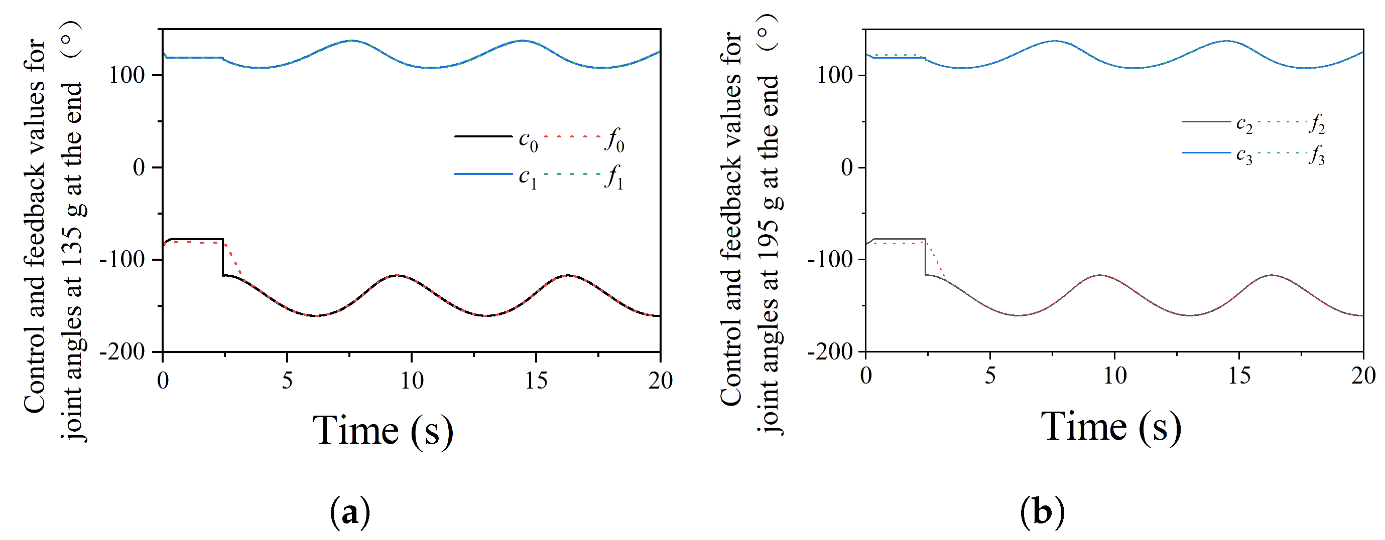
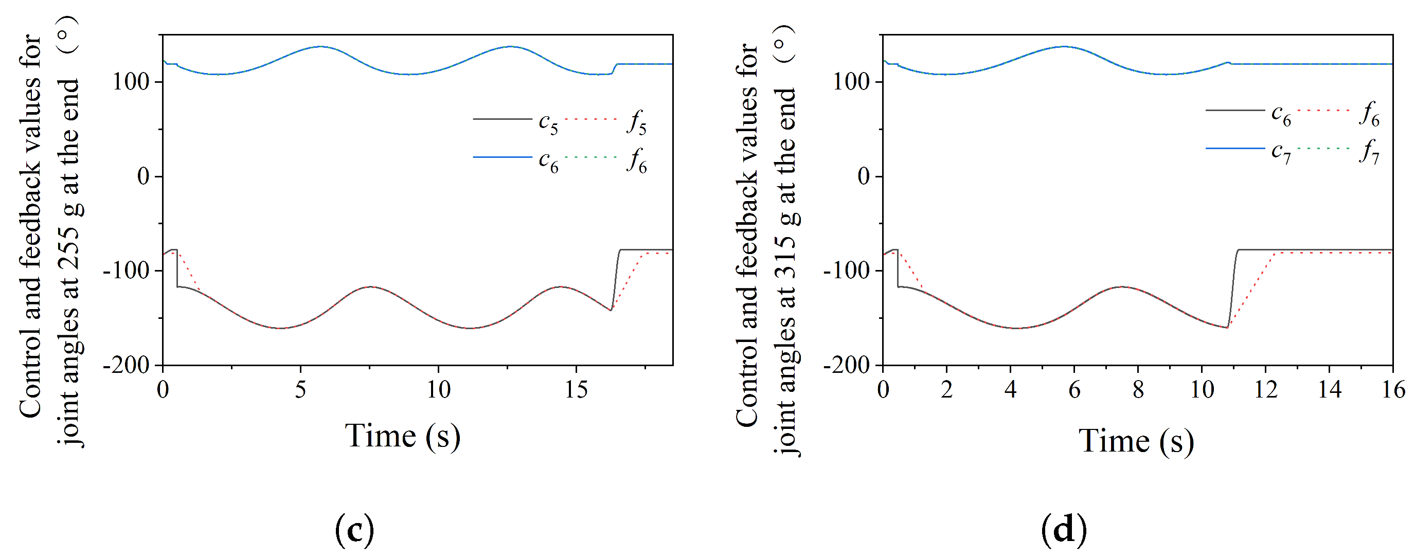
4.1. Motion Tracking of Robotic Arm

The robotic arm designed based on the load-adaptive hoisting mechanism uses a motor with parameters shown in Table 1. A distance sensor is installed at the base position, with a range of 0 to 25 mm. An encoder is installed at the gripper to obtain the rotation angle of the gripper. The motion trajectory of the robotic arm’s end effector is designed to observe the joint motor control angle commands and the feedback angle commands. The end effector’s trajectory is shown in Figure 9 and Figure 10. Under the same motion speed, the robotic arm’s motion trajectory was tracked with different loads: 135 g, 195 g, 255 g, and 315 g objects, as shown in Figure 9. Through comparative experiments, the error in the current experimental conditions is controlled within 1%, and the robotic arm can follow the control commands in real time. Since the robotic arm is designed for a bipedal robot with a point-foot design, the weight at the end of the arm has a significant impact on the robot, especially at the farthest end of the arm’s motion range. The fixed base experiment ensures that, under the premise of structural stability, the arm can easily handle 0.4 kg of load.

4.2. Slider Position Corresponding to Different Gripper Forces

In order to better verify the mechanical transmission characteristics of the mechanism proposed in the article, a pressure sensor is used to build a verification experiment. The experimental transposition is shown in Figure 11, and the pressure sensor is placed at the gripper.
Figure 12 shows the data of the force applied to the gripper at low, medium, and high speeds, corresponding to the curves V e l L = 25 rpm, V e l M = 200 rpm, and V e l H = 350 rpm, respectively, which are reduced to three speeds to cope with the needs of the gripper for different environments. In particular, different control requirements are made for fine and fast work of the task. Figure 12a presents the pressure values of the pressure sensor, and Figure 12b shows the raw data of the position sensor. The initial position is where the slider is closest to the base. When the slider is at the farthest position from the base, as shown at the minimum point in Figure 12b, Figure 12a is at the point with the maximum pressure. The reason why the red curve fluctuates from 4 s to 6 s is that the wire rope on the reel slips. During the low-speed operation, the motor does not reach the maximum motor torque. Instead, only the slider moves to the farthest end, so the gripping force of the gripper does not reach the maximum value. By comparing the curves at medium and high speeds, it is found that the maximum gripping force of the gripper depends on the maximum torque of the motor. And under the condition that the wire rope does not slip, the magnitude of the gripping force is in a direct proportional relationship with the distance of the slider. Moreover, when the motor rotates at a constant speed, both of them have a smooth transition.

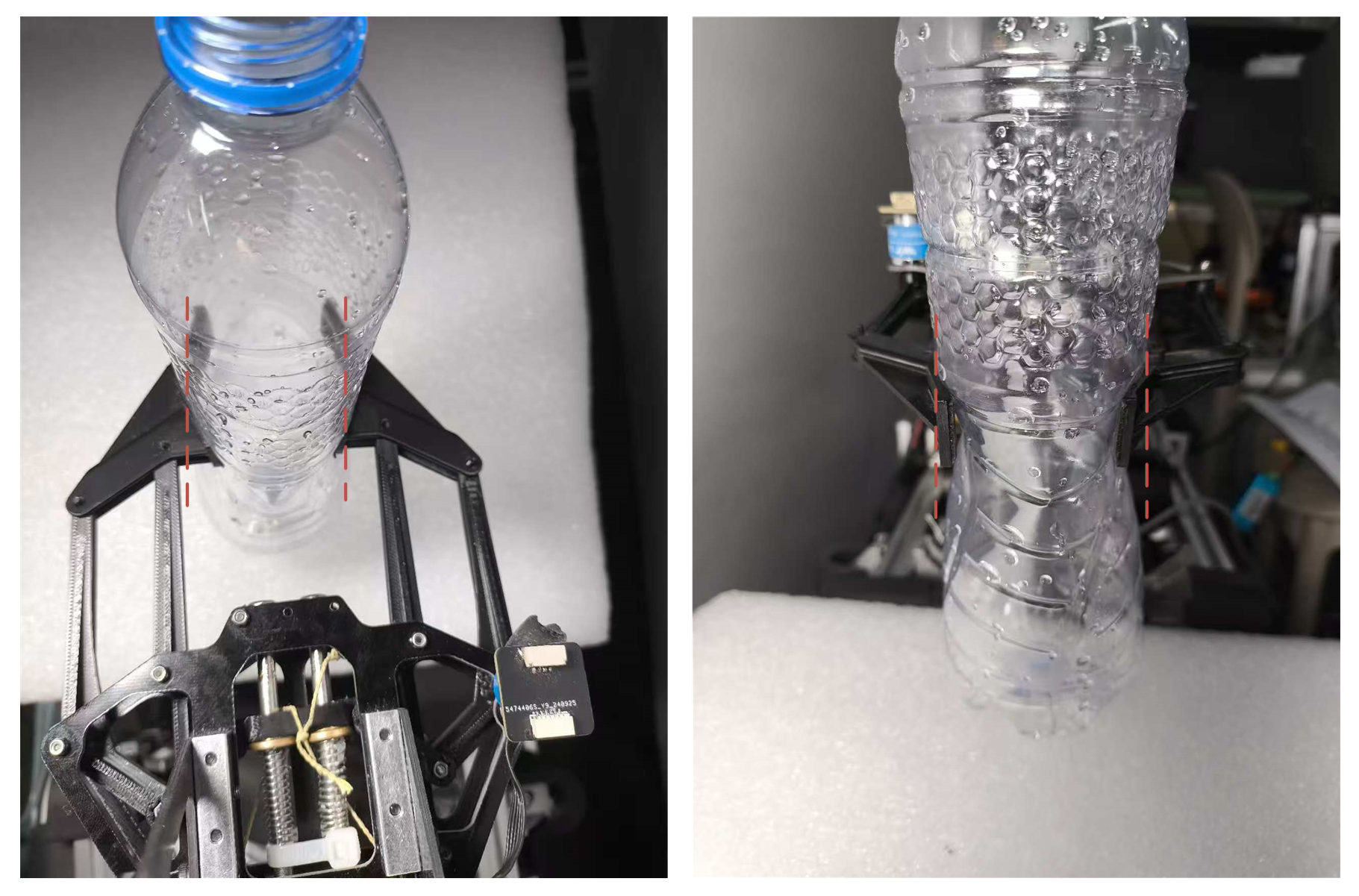
4.3. Motion Characteristics of the Slider When Grasping Objects with Different Stiffness

Four objects with different stiffness were selected for the gripper grasping experiment, namely square aluminum tubes, wire rollers, a water bottle filled with water, and an empty water bottle, as shown in Figure 13. Their stiffness decreases in turn, corresponding to curves M a , M b , M c , and M d . The original displacement curve of the slider is shown in Figure 14. As shown in the figure, when the drum is rotated at the same rotational speed, the higher the stiffness of the object is, the greater the slope of the curve will be, which indicates that the movement change in the slider position is faster. Regarding the change rates of the displacement curves of the slider corresponding to the four objects, k M a > k M b > k M c > k M d , and in one of the experiments of grasping a water bottle filled with water, the elasticity of the water bottle at the later stage caused a fluctuation in the data curve at the later stage, as shown by the M d in Figure 14. This characteristic enables the gripper to distinguish different objects by detecting the change rate of the slider’s position for the identification of different objects. Meanwhile, the angle sensor installed at the gripper can also clearly sense the deformation amount of the grasped object.

4.4. Force-Position Mixed Grasping Experiment

By combining the two position sensors on the robotic arm, as shown in Figure 11, grasping experiments were carried out on empty bottles that are extremely easy to deform, as shown in Figure 15. Among them, the slider is responsible for applying the gripping force on the empty bottles, while the angle sensor is used to detect the motion state of the gripper. For the gripper, there are two control modes. One is to control the gripping angle of the gripper, and the other is to control the clamping force of the gripper.
The two modes can also be used in combination. Just as shown in the experiment, when the target object is known to be a water bottle that is very easy to deform, the empty water bottle is grasped by setting the slider position offset to 5 mm. When the gripper angle deviation reaches 0.15 rad, the grasping action stops. Such a control mechanism not only ensures that the gripper can hold the object but also controls the force applied when grasping the object, so as not to cause damage to the target object.

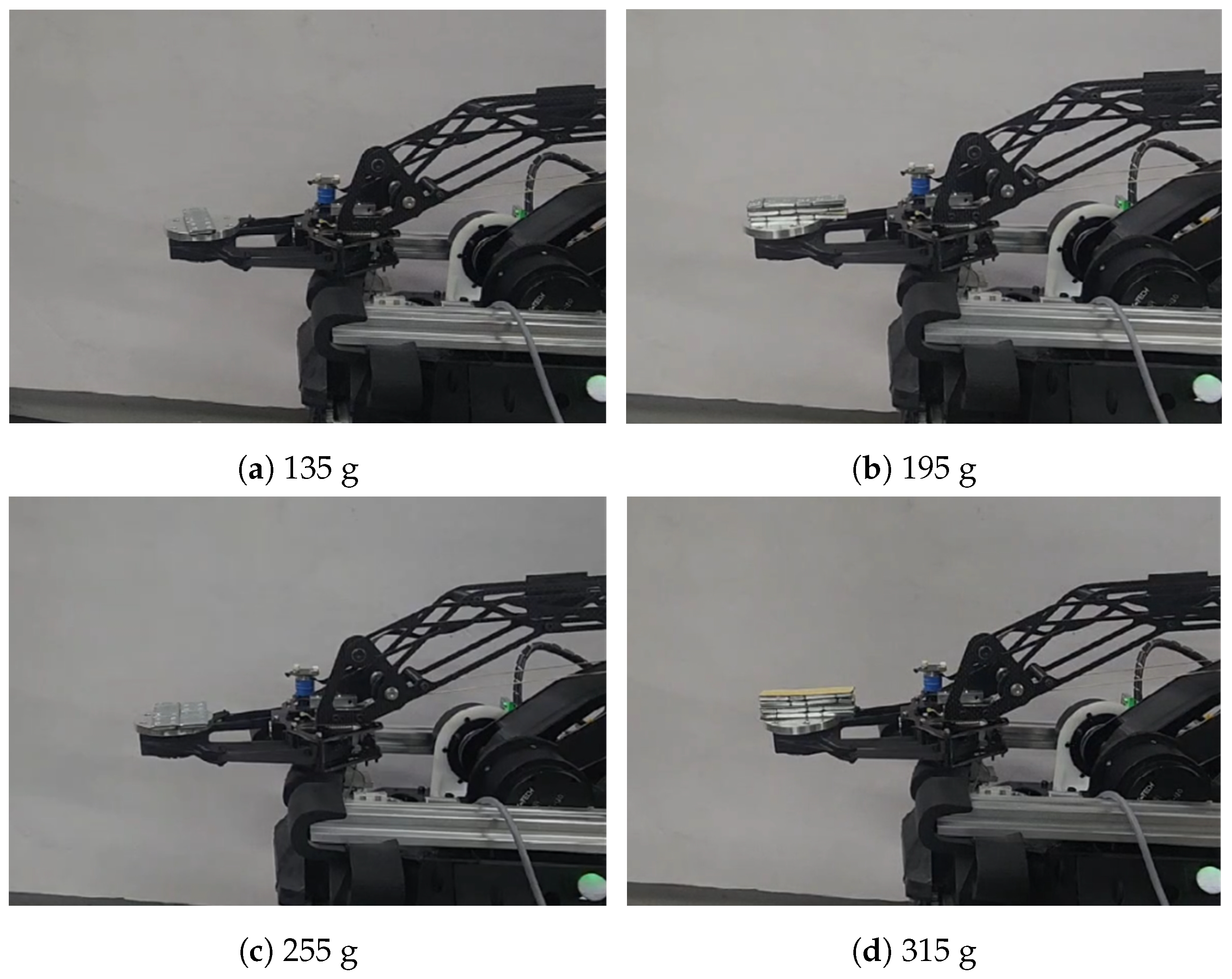
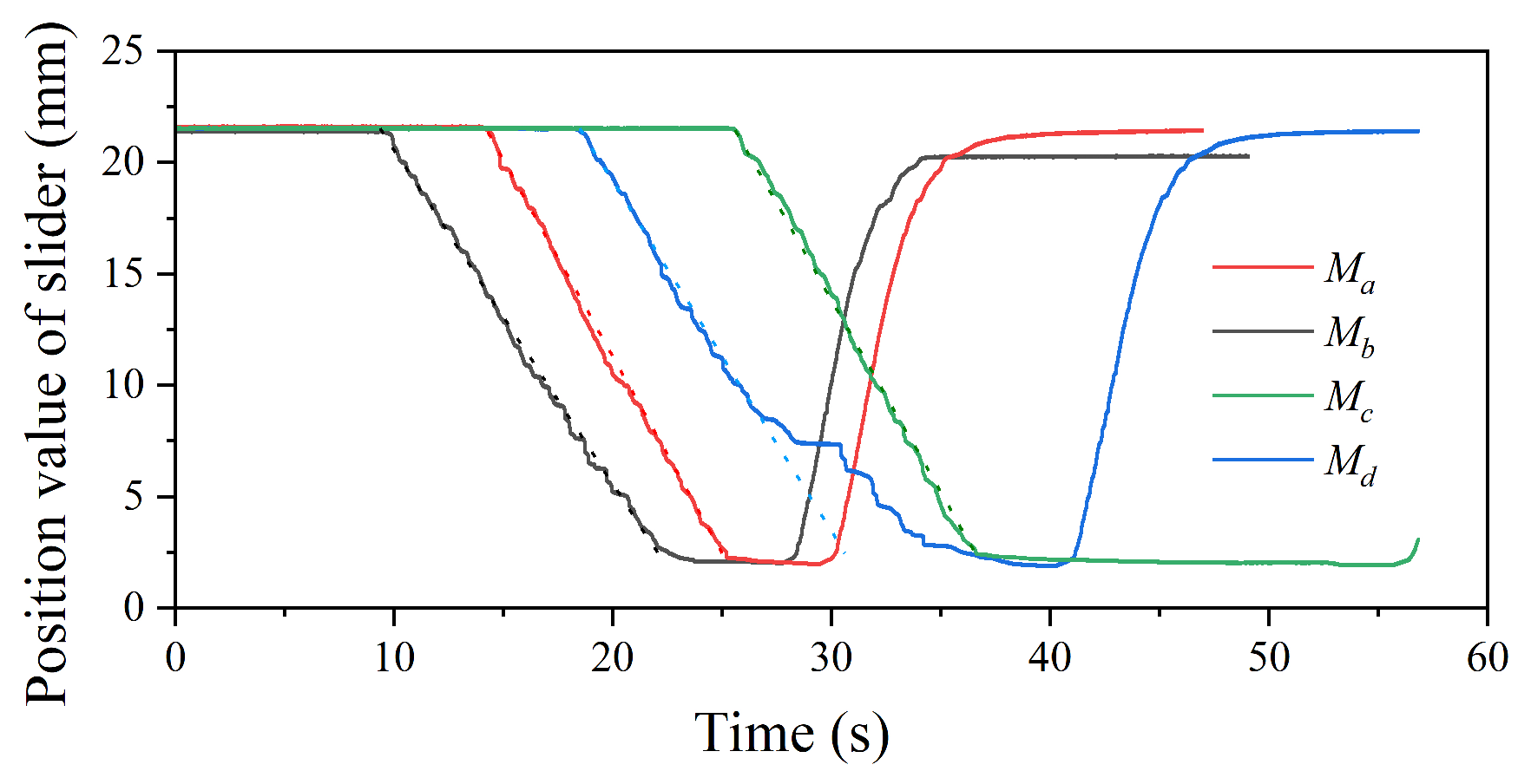
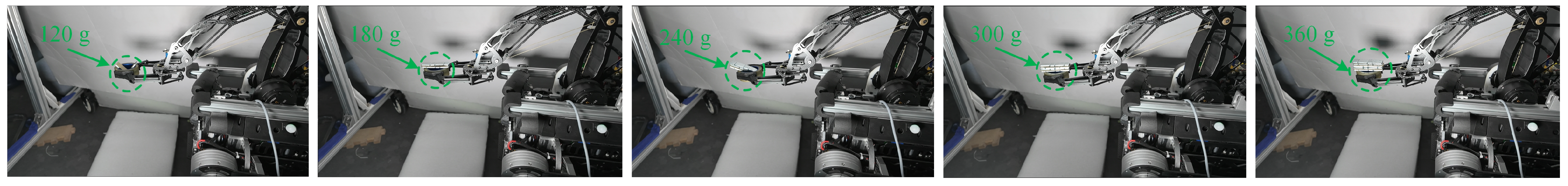
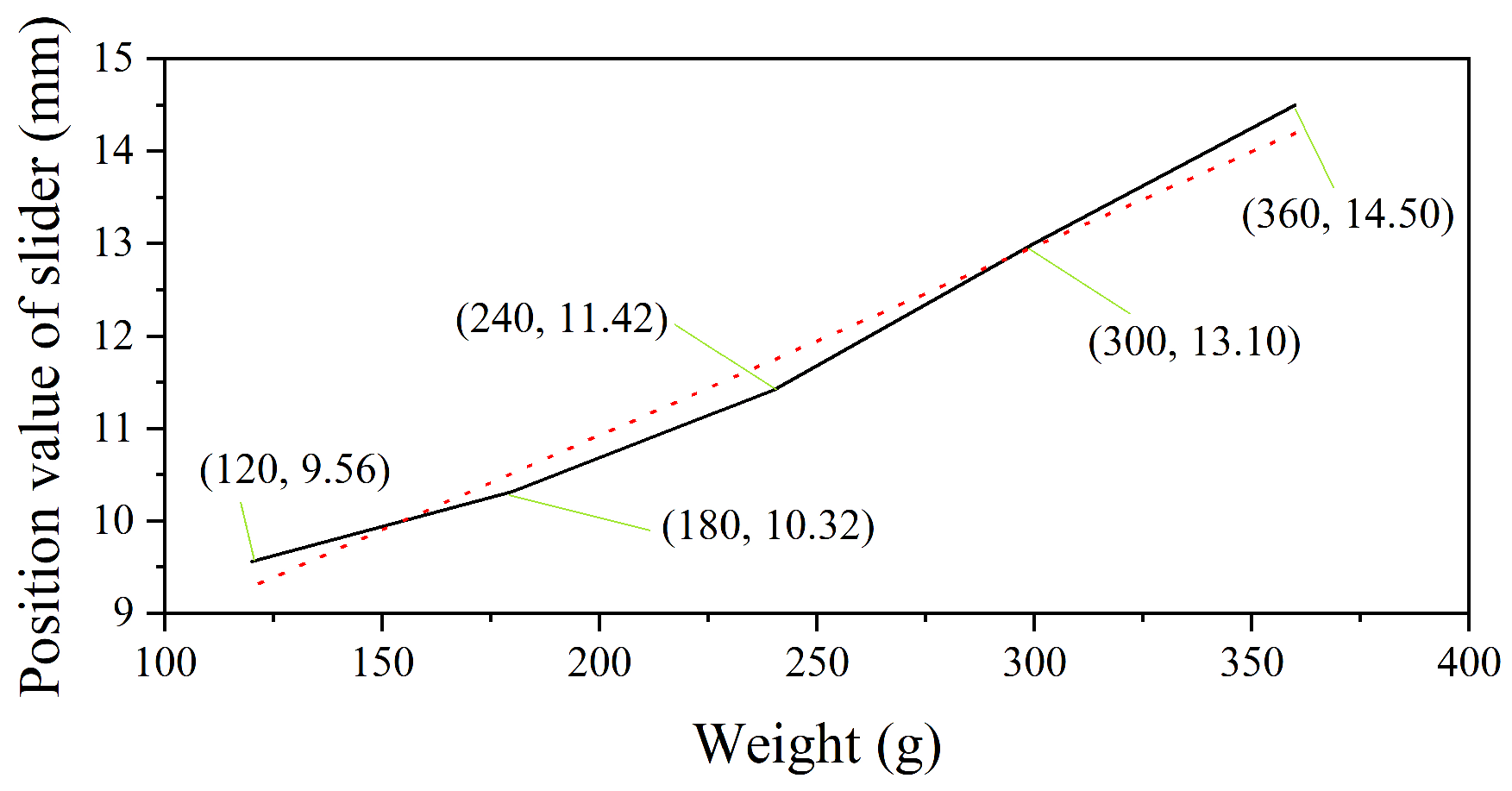
4.5. Slider Position Under Different Load Weights

Figure 16 shows the position of the slider at different weights. Initially, the slider is located at the far left, with the gripper exerting the maximum gripping force. When the gripper is slowly released, the object will fall off, and the slider position at that moment is recorded.
As shown in Figure 17, when only the weight of the grasped object is changed, the greater the weight is, the farther the position of the slider from the base will be, and they are in a direct proportional relationship. This also indicates that the greater the clamping force is, the clearer the relationship between the slider position and the gripping force of the gripper will be.

5. Discussion

In this study, the innovative design of a robotic arm based on an improved load-adaptive hoisting mechanism offers a number of significant advantages. First, by detecting the displacement of the slider, as shown in Figure 11 and Figure 12, the force of the gripper can be controlled without the need to install a force sensor on the end effector, thus reducing the complexity and weight of the hand gripper. Of course, it is also possible to install angle sensors at the gripper to obtain a more accurate gripper state, as in Figure 15. Second, the gripper’s adaptability to different object shapes realizes flexible gripping, and through the gripping experiments on objects with different stiffness, as in Figure 13 and Figure 14, the slider’s moving speeds of the objects with different stiffness are the same; furthermore, the higher the stiffness is, the faster the slider’s moving speed is, and such a characteristic can effectively recognize objects with significantly different stiffness. Third, the lightweight design of the robotic arm improves its overall dynamic motion performance. In the experiments of the gripper gripping objects, as shown in Figure 9 and Figure 10, the articulated motors are able to follow the control commands better. Finally, in the experiments of force transfer characteristics and grasping performance, as shown in Figure 16 and Figure 17, the heavier the clamped object is, the larger the displacement of the slider is, and they show a linear relationship, which better illustrates the effectiveness of the whole rope–transfer force transfer process.
The transmission ratio of a mechanical gripper designed based on a load-adaptive hoisting mechanism will change due to changes in the end load. When the load is high, the transmission ratio decreases and the output torque increases. Conversely, when the load is low, the transmission ratio increases and the output torque decreases. In this case, when grasping an object, the claw moves faster when not grasping the object. When grasping an object, it also smoothly provides grasping force to the grasped object, effectively grasping and protecting fragile or deformed objects. However, although the proposed design solution achieved good results, further exploration is still needed for the gripping task of a point-footed bipedal mobile platform, especially when the mobile platform is in motion, to ensure that the manipulator arm can perform the proper gripping task. Future work will focus on refining the control algorithm of the manipulator and further expanding the degrees of freedom of the manipulator arm to improve the performance of the system in unstructured environments.

6. Conclusions

Through improvements to the load-adaptive hoisting mechanism, the authors have innovatively designed a robotic arm device. The innovative structure introduced in this paper enables the force control of the gripper without adding force sensors at the end effector, and the gripper can adapt to the shape of the objects being grasped, achieving flexible gripping. The robotic arm adopts a lightweight design, which helps to reduce interference with the mobile platform during motion. Through experiments, the force transmission characteristics and excellent gripping performance of the mechanism have been validated.

Author Contributions

Conceptualization, Z.L. (Zhiguo Lu) and R.W.; methodology, R.W.; software, R.W. and Z.L. (Zhongqing Li); validation, Y.W.; formal analysis, R.W.; investigation, R.W.; resources, Z.L. (Zhongqing Li); data curation, R.W.; writing an article, R.W.; supervision, Z.L. (Zhiguo Lu); funding acquisition, Z.L. (Zhiguo Lu). All authors have read and agreed to the published version of the manuscript.

Funding

This research was funded by the National Key R & D Program of China (2018YFB1304504) and the Medical-Industrial Crossover Joint Fund of China (2022-YGJC-56).

Data Availability Statement

The original contributions presented in this study are included in the article. Further inquiries can be directed to the corresponding author.

Conflicts of Interest

The authors declare no conflicts of interest.

References

  1. Chen, F.; Xu, W.; Zhang, H.; Wang, Y.; Cao, J.; Wang, M.Y.; Ren, H.; Zhu, J.; Zhang, Y. Topology optimized design, fabrication, and characterization of a soft cable-driven gripper. IEEE Robot. Autom. Lett. 2018, 3, 2463–2470. [Google Scholar] [CrossRef]
  2. Shintake, J.; Cacucciolo, V.; Floreano, D.; Shea, H. Soft robotic grippers. Adv. Mater. 2018, 30, 1707035. [Google Scholar] [CrossRef] [PubMed]
  3. Wang, R.; Lu, Z.; Xiao, Y.; Zhao, Y.; Jiang, Q.; Shi, X. Design and Control of a Multi-locomotion Parallel-Legged Bipedal Robot. IEEE Robot. Autom. Lett. 2024, 9, 1993–2000. [Google Scholar] [CrossRef]
  4. Hubicki, C.; Grimes, J.; Jones, M.; Renjewski, D.; Spröwitz, A.; Abate, A.; Hurst, J. Atrias: Design and validation of a tether-free 3d-capable spring-mass bipedal robot. Int. J. Robot. Res. 2016, 35, 1497–1521. [Google Scholar] [CrossRef]
  5. Dämmer, G.; Gablenz, S.; Neumann, R.; Major, Z. Design, Topology Optimization, and Additive Manufacturing of a Pneumatically Actuated Lightweight Robot. Actuators 2023, 12, 266. [Google Scholar] [CrossRef]
  6. Lu, Z.; Wang, R.; Xiao, Y.; Liu, T.; Liu, C.; Zhao, H. A load-adaptive hoisting mechanism based on spring-loaded rope and variable radius reel. Adv. Robot. 2023, 37, 1520–1531. [Google Scholar] [CrossRef]
  7. Wang, Z.; Torigoe, Y.; Hirai, S. A prestressed soft gripper: Design, modeling, fabrication, and tests for food handling. IEEE Robot. Autom. Lett. 2017, 2, 1909–1916. [Google Scholar] [CrossRef]
  8. Hernandez, J.; Sunny, M.S.H.; Sanjuan, J.; Rulik, I.; Zarif, M.I.I.; Ahamed, S.I.; Ahmed, H.U.; Rahman, M.H. Current designs of robotic arm grippers: A comprehensive systematic review. Robotics 2023, 12, 5. [Google Scholar] [CrossRef]
  9. Hu, Q.; Dong, E.; Sun, D. Soft gripper design based on the integration of flat dry adhesive, soft actuator, and microspine. IEEE Trans. Robot. 2021, 37, 1065–1080. [Google Scholar] [CrossRef]
  10. Yao, P.; Zhou, K.; Lin, Y.; Tang, Y. Light-weight topological optimization for upper arm of an industrial welding robot. Metals 2019, 9, 1020. [Google Scholar] [CrossRef]
  11. Li, X.; Li, X.; Li, L.; Meng, Y.; Tian, Y. Load sharing design of a multi-legged adaptable gripper with Gecko-inspired controllable adhesion. IEEE Robot. Autom. Lett. 2021, 6, 8482–8489. [Google Scholar] [CrossRef]
  12. Zhakypov, Z.; Heremans, F.; Billard, A.; Paik, J. An origami-inspired reconfigurable suction gripper for picking objects with variable shape and size. IEEE Robot. Autom. Lett. 2018, 3, 2894–2901. [Google Scholar] [CrossRef]
  13. Xu, W.; Zhang, H.; Yuan, H.; Liang, B. A compliant adaptive gripper and its intrinsic force sensing method. IEEE Trans. Robot. 2021, 37, 1584–1603. [Google Scholar] [CrossRef]
  14. Jeong, S.H.; Kim, K.S. A 2-speed small transmission mechanism based on twisted string actuation and a dog clutch. IEEE Robot. Autom. Lett. 2018, 3, 1338–1345. [Google Scholar] [CrossRef]
  15. Jeong, S.H.; Kim, K.S.; Kim, S. Designing anthropomorphic robot hand with active dual-mode twisted string actuation mechanism and tiny tension sensors. IEEE Robot. Autom. Lett. 2017, 2, 1571–1578. [Google Scholar] [CrossRef]
  16. Tavakoli, M.; Batista, R.; Sgrigna, L. The UC softhand: Light weight adaptive bionic hand with a compact twisted string actuation system. Actuators 2015, 5, 1. [Google Scholar] [CrossRef]
  17. Park, J.; Park, J.i.; Seo, H.T.; Liu, Y.; Kim, K.S.; Kim, S. Control of tendon-driven (Twisted-string Actuator) robotic joint with adaptive variable-radius pulley. In Proceedings of the 2020 20th International Conference on Control, Automation and Systems (ICCAS), Busan, Republic of Korea, 13–16 October 2020; pp. 1096–1098. [Google Scholar]
  18. Sugihara, K.; Nozaki, T.; Murakami, T. Continuously variable transmission by high-speed path switching of linear electro-hydrostatic actuator. In Proceedings of the IECON 2019—45th Annual Conference of the IEEE Industrial Electronics Society, Lisbon, Portugal, 14–17 October 2019; Volume 1, pp. 3603–3608. [Google Scholar]
  19. Gan, Z.; Tang, H.; Treadway, E.; Gillespie, R.B.; Remy, C.D. Modeling and experimental evaluation of a variable hydraulic transmission. IEEE/ASME Trans. Mechatron. 2020, 25, 750–761. [Google Scholar] [CrossRef]
  20. Shin, W.; Park, S.; Park, G.; Kim, J. A passively adaptable toroidal continuously variable transmission combined with twisted string actuator. In Proceedings of the 2022 International Conference on Robotics and Automation (ICRA), Philadelphia, PA, USA, 23–27 May 2022; pp. 11409–11415. [Google Scholar]
  21. Wang, J.x.; Zhao, J.; Zou, H.; Yao, J. Design and simulation of a load-sensitive dual-speed transmission with a wide speed range. J. Braz. Soc. Mech. Sci. Eng. 2019, 41, 1–7. [Google Scholar] [CrossRef]
  22. Huang, L.; Yu, T.; Jiao, Z.; Li, Y. Research on power matching and energy optimal control of active load-sensitive electro-hydrostatic actuator. IEEE Access 2020, 9, 51121–51133. [Google Scholar] [CrossRef]
  23. Takaki, T.; Yamasaki, Y.; Ishii, I. Load-sensitive continuously variable transmission using an oblique feed screw for parallel-jaw grippers. In Proceedings of the 2011 International Symposium on Micro-NanoMechatronics and Human Science, Nagoya, Japan, 6–9 November 2011; pp. 507–510. [Google Scholar]
  24. Ueki, K.; Sato, R.; Ming, A.; Shimojo, M.; Hammadi, M.; Choley, J.Y. Development of knee joint mechanism with variable transmission and joint stop for bipedal robot inspired by human structure. In Proceedings of the 2020 21st International Conference on Research and Education in Mechatronics (REM), Cracow, Poland, 9–11 December 2020; pp. 1–6. [Google Scholar]
  25. Liu, Y.; Guo, S.; Zhang, S.; Boulardot, L. Modeling and analysis of a variable stiffness actuator for a safe home-based exoskeleton. In Proceedings of the 2018 IEEE International Conference on Mechatronics and Automation (ICMA), Changchun, China, 5–8 August 2018; pp. 2243–2248. [Google Scholar]
  26. Kernbaum, A.S.; Kitchell, M.; Crittenden, M. An ultra-compact infinitely variable transmission for robotics. In Proceedings of the 2017 IEEE International Conference on Robotics and Automation (ICRA), Singapore, 29 May–3 June 2017; pp. 1800–1807. [Google Scholar]
  27. Lenzi, T.; Cempini, M.; Hargrove, L.J.; Kuiken, T.A. Actively variable transmission for robotic knee prostheses. In Proceedings of the 2017 IEEE International Conference on Robotics and Automation (ICRA), Singapore, 29 May–3 June 2017; pp. 6665–6671. [Google Scholar]
  28. Chen, S.; Xu, L.; Xu, H.; Liu, J.; Cheng, G.; Cao, K. Principle, design and simulation of a novel continuously variable transmission for robots. In Proceedings of the 2019 IEEE 8th Joint International Information Technology and Artificial Intelligence Conference (ITAIC), Chongqing, China, 24–26 May 2019; pp. 73–78. [Google Scholar]
  29. Kim, J.H.; Jang, I.G. Optimization-based investigation of bioinspired variable gearing of the distributed actuation mechanism to maximize velocity and force. IEEE Robot. Autom. Lett. 2020, 5, 6326–6333. [Google Scholar] [CrossRef]
  30. Lee, E.; Song, H.; Jeong, J.; Jeong, S. Mechanical variable magnetic gear transmission: Concept and preliminary research. IEEE Robot. Autom. Lett. 2022, 7, 3357–3364. [Google Scholar] [CrossRef]
  31. ABB. 2024. Available online: https://new.abb.com/products/robotics/zh/robots/articulated-robots/irb-460 (accessed on 17 December 2024).
Figure 1. Physical image of the robotic arm based on the load-adaptive hoisting mechanism installed on a bipedal robot.
Actuators 14 00071 g001
Figure 4. Schematic diagram and force schematic of a rope driven manipulator.
Actuators 14 00071 g004
Figure 5. Schematic diagram of the winding method of the rope. The red solid line represents the winding method of the rope, while the green solid line with an arrow represents the approximate length.
Actuators 14 00071 g005
Figure 6. The reel’s schematic diagram of the improved hoisting mechanism.
Actuators 14 00071 g006
Figure 7. Simplified schematic diagram of the position relationship of the linkage of the robotic arm.
Actuators 14 00071 g007
Figure 8. The control flow chart of the robotic arm.
Actuators 14 00071 g008
Figure 9. The trajectory following experiments of a robotic arm gripper when gripping different weights.
Actuators 14 00071 g009
Figure 10. The experimental data on trajectory following of robotic arm gripper when gripping different weights (ad).
Actuators 14 00071 g010aActuators 14 00071 g010b
Figure 11. Schematic diagram of the position sensor and pressure sensor locations.
Actuators 14 00071 g011
Figure 12. The experimental data curves for position and pressure sensors.
Actuators 14 00071 g012
Figure 13. The gripper gripped a selection of objects of different stiffness for the experiment.
Actuators 14 00071 g013
Figure 14. The displacement curve of the slider when the gripper grips and releases the object.
Actuators 14 00071 g014
Figure 15. Experiments on grabbing empty bottles that are highly deformable.
Actuators 14 00071 g015
Figure 16. The slider displacement experiment with different weights.
Actuators 14 00071 g016
Figure 17. The slider displacement curve of different weight.
Actuators 14 00071 g017
Table 1. Attribute parameters of each component of the robot arm.
ParametersDescriptionValue
m 0 Weight of base146 g
m 1 Weight of joint motor436 g
m 2 Weight of hoist mechanism160 g
m 3 Weight of upper arm140 g
m 4 Weight of forearm120 g
m 5 Weight of gripper180 g
τ M Peak torque of joint motor7 N.m
S M Maximum speed of joint motor235 rpm
τ m Peak torque of LAHM’s motor1 N.m
S m a x Maximum speed of LAHM’s motor416 rpm
x 0 , x 1 , x 2 Length coordinates of the reel20 mm, 8 mm
R m a x , R m i n Radius of the reel10 mm, 28.4 mm, 33.4 mm
l 1 , l 2 , l 3 Schematic diagram for solving the kinematics of a robotic arm linkage length60 mm, 140 mm, 205 mm
L 0 , L 1 , L 2 , L 3 , L 4 Vector length of rope points86 mm, 140 mm, 205 mm, 35 mm
Disclaimer/Publisher’s Note: The statements, opinions and data contained in all publications are solely those of the individual author(s) and contributor(s) and not of MDPI and/or the editor(s). MDPI and/or the editor(s) disclaim responsibility for any injury to people or property resulting from any ideas, methods, instructions or products referred to in the content.

