Article

Passive Frequency Tuning of Kinetic Energy Harvesters Using Distributed Liquid-Filled Mass

1
Department of Mechanical Engineering, University of New Mexico, Albuquerque, NM 87131, USA
2
Nanoscience and Microsystems Engineering, University of New Mexico, Albuquerque, NM 87106, USA
3
Center for High Technology Materials, University of New Mexico, Albuquerque, NM 87106, USA
*
Author to whom correspondence should be addressed.
Actuators 2025, 14(2), 78; https://doi.org/10.3390/act14020078
Submission received: 30 December 2024 / Revised: 29 January 2025 / Accepted: 3 February 2025 / Published: 7 February 2025
(This article belongs to the Section Actuators for Robotics)

Abstract

:
Micro-scale kinetic energy harvesters are in large demand to function as sustainable power sources for wireless sensor networks and the Internet of Things. However, one of the challenges associated with them is their inability to easily tune the frequency during the manufacturing process, requiring devices to be custom-made for each application. Previous attempts have either used active tuning, which consumes power, or passive devices that increase their energy footprint, thus decreasing power density. This study involved developing a novel passive method that does not alter the device footprint or power density. It involved creating a proof mass with an array of chambers or cavities that can be individually filled with liquid to alter the overall proof mass as well as center of gravity. The resonant frequency of a rectangular cantilever can then be altered by changing the location, density, and volume of the liquid-filled mass. The resolution can be enhanced by increasing the number of chambers, whereas the frequency tuning range can be increased by increasing the amount of liquid or density of the liquids used to fill the cavities. A piezoelectric cantilever with a 340 Hz initial resonant frequency was used as the testing device. Liquids with varying density (silicone oil, liquid sodium polytungstate, and Galinstan) were investigated. The resonant frequencies were measured experimentally by filling various cavities with these liquids to determine the tuning frequency range and resolution. The tuning ranges of the first resonant frequency mode for the device were 142–217 Hz, 108–217 Hz, and 78.4–217 Hz for silicone oil, liquid sodium polytungstate, and Galinstan, respectively, with a sub Hz resolution.

1. Introduction

Kinetic energy harvesting devices convert mechanical energy into usable electrical power. Kinetic energy harvesters typically utilize vibrations from the surrounding environment, which induce stress/strain to the harvester, which uses various methods such as piezoelectrics, electromagnetics, electrostatics, or triboelectrics to convert mechanical energy into electrical energy [1,2]. This is a promising technology due to the abundance of vibration sources in the environment, which allow the harvesters to be used as sustainable energy sources [3]. Microelectromechanical systems (MEMS) kinetic energy harvesters offer additional advantages due to their small size; they could be used to power Internet of Things (IoT) devices and wireless sensor networks (WSN). MEMS energy harvesters can also be applied to robotics or human use [4,5,6,7,8]. Each kinetic energy harvesting mechanism has advantages and disadvantages, but piezoelectric-based energy harvesters have been extensively investigated as they can generate high voltage and a high power density and can be more easily fabricated at the MEMS scale compared to 3D electrostatics and electromagnetics [9,10,11,12]. Piezoelectric-based kinetic energy harvesters typically have a more simplistic design, typically consisting of a cantilever with a three-layer structure (metal/piezoelectric/metal). The demand for sensors for IoT devices, WSNs, human health sensing, and robotic sensors/actuators has been rapidly increasing, and thus, a method for reducing or eliminating batteries to create a self-sustaining system is needed.
Most of the challenges associated with kinetic energy harvesters are related to frequency. Due to the mechanism of action, these devices maximize performance when they vibrate in the first resonant frequency mode. In addition, most applications have low-frequency vibrations of less than 250 Hz, which, due to the laws of scaling, is a disadvantage for MEMS energy harvesters, as scaling dimensions down results in an increase in the resonant frequency. Therefore, MEMS devices often have a large proof mass with which to reduce the frequency to meet specifications [13,14,15,16,17,18]. MEMS energy harvesters typically have a silicon structural layer that results in a high Q-factor or low bandwidth of 1–3 Hz [19,20,21,22,23]. The high Q-factor allows for high-power conversion when the resonant frequency of the device matches the vibration source, but if the vibration source deviates by even a few Hz, the power generated is significantly reduced, which limits the performance. Therefore, it is necessary to match the resonant frequency of the device with the vibration source to maximize efficiency.
Researchers have investigated several methods to overcome these challenges with resonant frequency. The most common method investigated involves widening the bandwidth to account for any variation in either the cantilevers’ resonant frequency due to manufacturing or stress and to account for deviation in the vibration sources frequency spectrum. Several common techniques used to increase the bandwidth involve lowering the Q-factor using non-linear dynamics [24,25,26], an impact or high-frequency plucking converter [27,28,29,30], and a movable mass [31,32,33,34,35,36,37] or creating an array of cantilevers with varying dimensions [38]. The amount of increase in bandwidth can vary between 10 and 200 Hz. However, each of these methods results in decreasing the power density by either decreasing the Q-Factor or increasing the footprint. Typically, the higher the bandwidth, the lower the power density.
Researchers have also investigated methods of tuning the resonant frequency of the cantilever to match the frequency of the vibration source. There are two reasons for tuning the frequency. One is tuning the frequency during operation, where the frequency of the cantilever is tuned to match the vibration sources frequency to account for the changing frequency spectrum from the source. The other reason is to tune the frequency during the manufacturing process to ensure that the resonant frequency matches the specification. Both methods are designed to optimize power density. There are multiple methods used to tune the frequency, including altering the stiffness of the beam through light or electrical simulation [17,39,40], the use of magnetics to alter the mass distribution [22,41,42,43,44], and dimensional changes [45,46,47], but a lot of these methods require power to tune the frequency, which ultimately decreases the overall power efficiency of the harvester. Therefore, a passive method for tuning the frequency is desired.
Tuning the frequency during manufacturing is especially important for MEMS devices, as one of the big advantages of MEMS is their ability to be batch-fabricated. However, if each device needs to be custom-made, then devices do not need to be batch-fabricated. Therefore, to take advantage of the batch fabrication process, it would be useful to develop a device that can be easily tuned during fabrication or post fabrication. For instance, since most applications operate at under 250 Hz, it would be advantageous to manufacture a single energy harvester operating at 250 Hz and then tune the frequency between 1 and 250 Hz so that a single device can be batch-fabricated to suit almost all applications. Passive tuning is desired as this requires no power consumption, thus maximizing power efficiency. A common method used by researchers to tune the frequency is to add or subtract mass to the cantilever [48]. Recently, there have been several studies investigating similar passive tuning mechanisms, including altering the proof mass and distribution of the mass along the cantilever. A custom proof mass with an array of chambers or cavities has been used, where each cavity could be individually filled with nano/microparticles [49,50], thus adding mass at specific locations. The mechanism of operation involved altering the overall mass of proof mass and altering the location or distribution of the proof mass along the cantilever, which ultimately changes the center of gravity. Through altering the mass and distribution of the mass, the frequency can be tuned. However, previous attempts using solid masses have resulted in poor repeatability and reliability due to variations in the fill factor caused from air spaces between particles.
This paper describes a novel method of passively tuning the frequency of a rectangular cantilever structure using a proof mass with an array of cavities, which can be individually filled with liquids with varying densities. Liquid-filled cavities aim to resolve the issue with repeatability and reliability, as the dispensed volume of liquid can be easily controlled to overcome the previous fill factor issues with nanoparticles fillers. This paper focuses on the experimental validation of the proposed concept using a custom-made proof mass with an array of cavities integrated on a rectangular piezoelectric cantilever. Liquids with varying densities were used to fill the cavities to determine their tuning capabilities, including their range and resolution. The goal was to maximize the range (100s of Hz) while being able to have high resolution (<0.1 Hz). This study investigated the effects of varying the density, volume, and location.

2. Materials and Methods
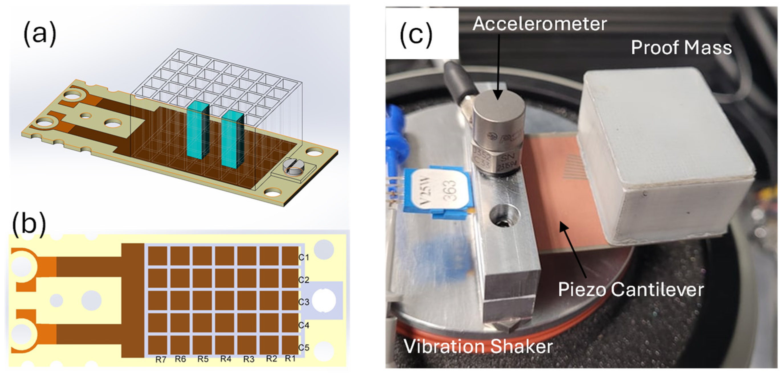
2.1. Concept

The first resonant frequency mode of a rectangular cantilever with proof mass can be estimated using the simplistic Euler–Bernoulli equation:
f = 1 2 π E 4 m w t 3 L 3                      
where E, m, w, t, and L are the elastic modulus, mass, width, thickness, and length of the cantilever beam, respectively [51]. The above equation is a simplistic equation meant to demonstrate how changing the dimensions, elastic modulus, and proof mass affect the resonant frequency. The thickness and length have the largest impact, but these are difficult to change. Laser etching has been demonstrated previously for fine tuning the frequency in MEMS by reducing the length or increasing the number of holes in the cantilever [52,53]. However, laser removal would need to be performed on an individual device and is not batch fabrication-compatible and would have increased costs. As mentioned in the Introduction, the elastic modulus can be changed using specialized materials, but altering the modulus typically requires power and thus decreases the overall efficiency. Therefore, the most approachable method for tuning the frequency is by altering the mass. However, Equation (1) assumes that the mass is a single point at the center of gravity. But changing the location of the center of gravity of the proof mass also affects the resonant frequency, as shown by Equation (2), which combines Equation (1) with the Rayleigh principle [54]:
f = 1 2 π E w t 3 12 M L 3 6 r 2 + 6 r + 2 8 r 4 + 14 r 3 + 10.5 r 2 + 4 r + 2 3
where r = Lc/L, where L is the length of the cantilever, and Lc is the length to the center of gravity. Hence, when the center of gravity is shifted to the free end, the frequency will decrease, and when it is shifted to the tethered end, the frequency will increase. Therefore, if the same overall mass is located at the free end, the cantilever will have a lower frequency than if the same mass was located toward the tethered end.
The concept for tuning the frequency investigated in this study involved developing a 3D printed custom-made proof mass that consists of 35 cavities arranged in a 5 × 7 array. To tune the frequency, individual cavities were filled with various liquids. The liquid-filled cavities alter the overall mass of the system, and the array of cavities alter the mass’s location along the cantilever, allowing us to investigate effects of mass and location on the resonant frequency. Thus, the overall mass could be altered as well as the center of gravity (both along the length and width of the cantilever). In varying the locations of the cavities, density of the liquids, number of cavities filled, and the volume (filling cavities 25–100%), the resonant frequency should be able to be tuned over a wide frequency spectrum, while having a high frequency resolution [55]. According to Equation (2), the frequency range is dependent on the initial frequency of the cantilever, with an empty proof mass representing the highest frequency that can be achieved. Adding liquid mass to the proof mass will always result in lowering the frequency, but how much it is lowered depends on the location and overall mass. Therefore, to maximize the range, the initial frequency and density of the liquid used should be large, and the overall amount of liquid that can be added should be high. The resolution can be lowered by reducing the size of the cavities and increasing the number of cavities.

2.2. Experimental Methods

A commercial lead zirconate titanate (PZT) piezoelectric energy-harvesting cantilever beam was used (Mide S233-H5FR-1107XB (Piezo.com, Woburn, MA, USA)) with dimensions 53 × 23.4 × 0.83 mm (L, w, and t). It had 2 layers of PZT on the cantilever with dimensions of 27.8 × 18 mm. The device consisted of multiple layers consisting of FR4 epoxy, Copper, PZT 5H, Copper, FR4, Copper, PZT 5H, Copper, and FR4. No modifications were made to the cantilever except for the addition of the proof mass. The commercial energy harvester was used to validate the concept at the macro-scale. Polylactic acid (PLA) material was used to 3D print the proof mass, which consisted of a 5 × 7 array of cavities. The individual cavities were 3 × 3 × 10 mm (L, w, and height) with a spacing of 0.5 mm between the cavities. Figure 1a illustrates the piezoelectric cantilever with a proof mass consisting of an array of cavities. The nomenclature used throughout this paper includes Cij for the column and Rji for the row, where i is the column number and j is the row number. The 1st column is to the left of the central line, and row 1 is closer to the free end, as shown in Figure 1b. Figure 1a illustrates the filling of C54 and C52, which are located in the 5th column and the 2nd and 4th row. The proof mass was secured to the cantilever using a nylon screw at the free end. A nylon screw was used to reduce the additional mass from the screw. The entire cantilever was clamped onto a vibration shaker (Labworks ET-139) as shown in Figure 1c. A 3D printed capping layer was used, but to reduce the mass, a Parylene coating capping layer could be used [56] to create a conformal coating over the liquid to prevent leaks for long-term use.
A vibration shaker system was used to control the applied frequency and acceleration. A constant acceleration of 0.2 g was applied for all the studies. Increasing acceleration affects the voltage output, but the goal of this study was to tune the frequency. The peak-to-peak voltage (Vpp) was monitored using an oscilloscope, where the wires were connected to the top and bottom electrodes. A frequency sweep between 5 and 300 Hz with 0.05 Hz increments was used, and the Vpp was measured as a function of frequency. The resonant frequency was considered the frequency that resulted in the highest Vpp. The range of frequency tuning was determined by measuring the change in frequency with empty (air) cavities and the frequency with all cavities filled with their respective liquid. The resolution of the frequency was found by filling each cavity and calculating the smallest resonant frequency difference between them. The bandwidth was calculated as the full width at half maximum (FWHM).
Initially, the frequency of the cantilever with an empty proof mass was measured, and this was considered the control. Three different liquids were investigated: silicone oil (Sigma Aldrich, Saint Louis, MI, USA, with a density of 1.04 g cm−3), liquid Sodium Polytungstate (GEO Liquids, Prospect Heights, IL, USA, with a density of 3.1 g cm−3), and Galinstan (RotoMetals, San Leandro, CA, USA, with a density of 6.44 g cm−3). The liquids were dispensed in the cavities using a liquid-dispensing system (EFD Ultimus Plus, Westlake, OH, USA), which allowed us to control the volume of liquid dispensed into each cavity. The liquid-dispensing systems allowed us to control the time per step, overall time, and pressure, allowing us to dispense a precise amount of liquid each time within 0.05% accuracy. Experimentally, we investigated the effects of filling individual cavities along a row and column, as well as filling all cavities while varying the volume used to fill the cavities.

3. Results and Discussion
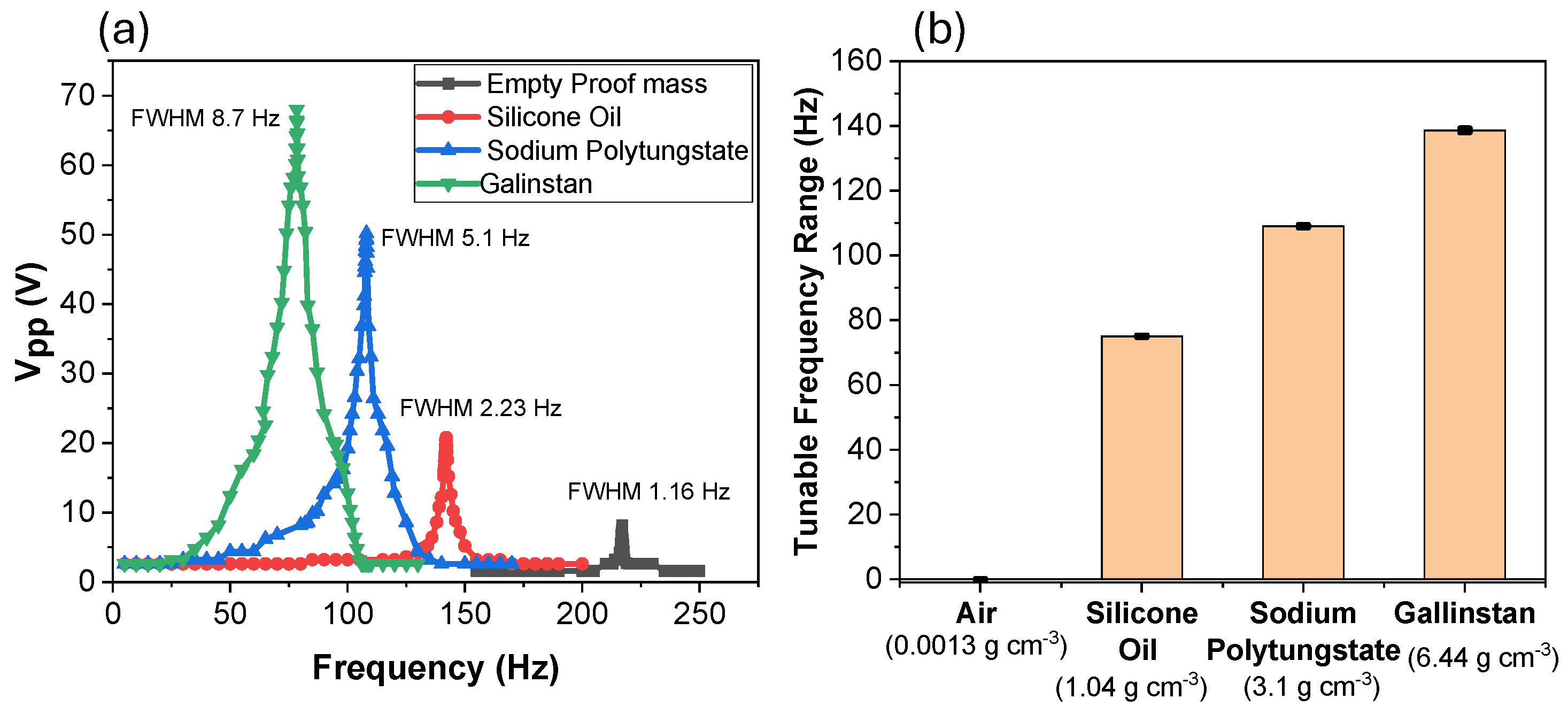
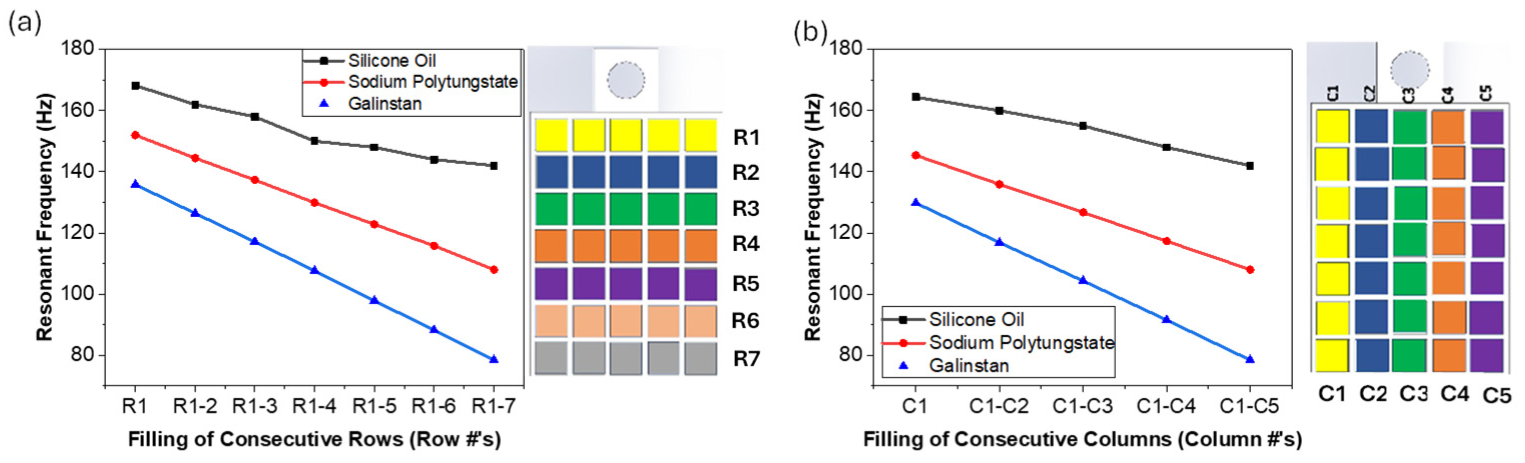
3.1. Tuning Range

To investigate the concept and the frequency tuning range potential, all of the cavities were filled to 100% volume with each liquid, and the control was a completely empty cavity (filled with air). The initial frequency of the cantilever without a proof mass was approximately 340 Hz, which is lower than the manufacturer’s suggested frequency of 443 Hz, which is likely due to the clamping mechanism. Adding the 3D printed proof mass, nylon screw, and capping layer with cavities filled with air (empty) reduced the resonant frequency to 217 Hz. The control had a Vpp of 8.2 V and a bandwidth of 1.16 Hz, which is similar to the values of other MEMS energy harvester devices. The Vpp and bandwidth would be increased with higher acceleration, but the purpose of this study was to investigate the tuning capability.
Filling all the cavities with 100% volume allowed us to determine the maximum frequency range possible with the current proof mass. The frequency range was determined by taking the difference in the peak resonant frequency between the empty proof mass and the 100% filled proof mass. The Vpp as a function of frequency for all the liquids is shown in Figure 2a, and the tuning range is shown in Figure 2b. The frequency range obtained when filled with silicone oil was 142 Hz−217 Hz (Δ75 Hz), that of sodium polytungstate was 108 Hz−217 Hz (Δ109 Hz), and that of Galinstan was 78.4 Hz−217 Hz (Δ138.6 Hz). As denser liquid was used to fill the cavities, the resonant frequency decreased as expected, as denser liquid would increase the overall proof mass. As the overall mass increased, the Vpp also increased, which was also expected, as the larger mass causes larger stress/strain on the cantilever with the same applied acceleration [57]. The bandwidth also increased with increasing mass, which is due to the increasing Vpp. The bandwidths were 1.16, 2.23, 5.1, and 8.7 Hz for the empty and silicone oil-, sodium polytungstate-, and Galinstan-filled proof masses, respectively. The frequency range was highly repeatable, as the standard error bars shown in Figure 2b are within 1 Hz. This was achieved by controlling the exact amount of liquid that was being dispensed into each cavity. Previous results using solid nano/microparticles as fillers demonstrated low repeatability due to the fill factor of the solid particles [49,50]. The results illustrated in Figure 2 are for the particular proof mass design, but the concepts would hold true with various designs. To increase the frequency range further, one could decrease the initial proof mass, which would give a higher initial frequency, or one could add more liquid by altering the proof mass to hold more liquid.
Figure 2 demonstrates the maximum and minimum resonant frequency with various liquids. However, tuning the resonant frequency can also be performed by altering the amount of liquid used in each cavity. The results of altering the amount of liquid filled into each cavity are shown in Figure 3, where Figure 3a shows the Vpp as a function of frequency for the sodium polytungstate, where all cavities were filled to 25, 50, and 100% volume. The 100% filled volume has the same results, as shown in Figure 2a, with a resonant frequency of 108 Hz. However, when the cavities were filled with 50% and 25% volume, the resonant frequencies were 139 Hz and 156.5 Hz, respectively. As mentioned above, the Vpp decreases as the mass decreases due to less stress/strain on the cantilever. Compared to the control, the frequency tuning ranges for the 25% filled cavities were 60.5 Hz and 78 Hz for the 50% filled cavities. This illustrates that the frequency tuning range can be altered by changing not only the density of the liquid but also the volume of liquid used in each cavity. Within the same proof mass, each cavity could be filled to different levels to give the user fine-tuning capabilities. The FWHM value did increase slightly when using lower-filled cavities, which is likely due to some sloshing effects caused from the cavity not being filled all the way [33,34]. However, a parylene capping layer could be used to reduce any sloshing affects [56].
To further demonstrate the effect of altering the amount of filling in each cavity, we measured the resonant frequency as we filled individual cavities along middle column 3 with varying fill volumes (25–100%) with sodium polytungstate. The results are illustrated in Figure 3b, with the change in resonant frequency from the control (217 Hz) highlighted in parenthesis. Filling a single individual cavity at the free end (C31) resulted in frequency changes of 45.1, 41.3, 37.4, and 33.6 Hz for the 100%, 75%, 50%, and 25% filled cavities, whereas if cavity C37 (the closest cavity to the tethered end) was filled, the changes in frequency from the control were 41.2, 37.7, 33.8, and 29.8 for the 100%, 75%, 50%, and 25% filled cavities, respectively. This illustrates that filling a single cavity can significantly alter the resonant frequency and that it can be controlled by altering the location of the filled cavity and the volume of liquid used. The slope of each of the graphs was similar, demonstrating that the resonant frequency is altered linearly by changing the location of the center of gravity along the cantilever.

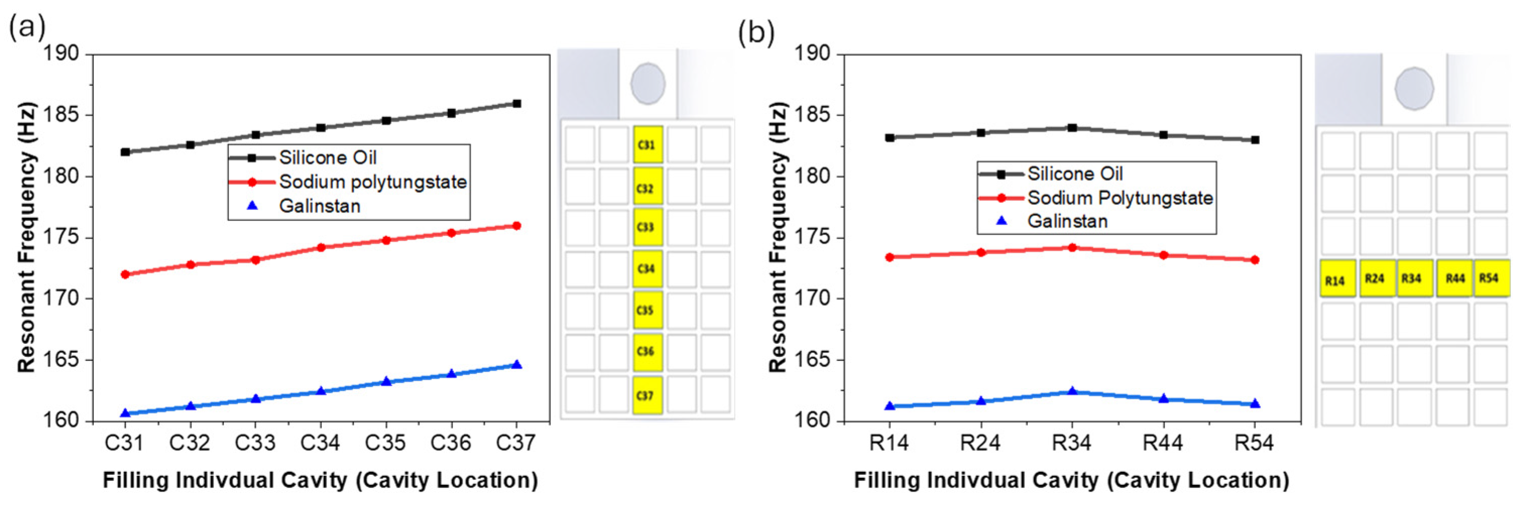
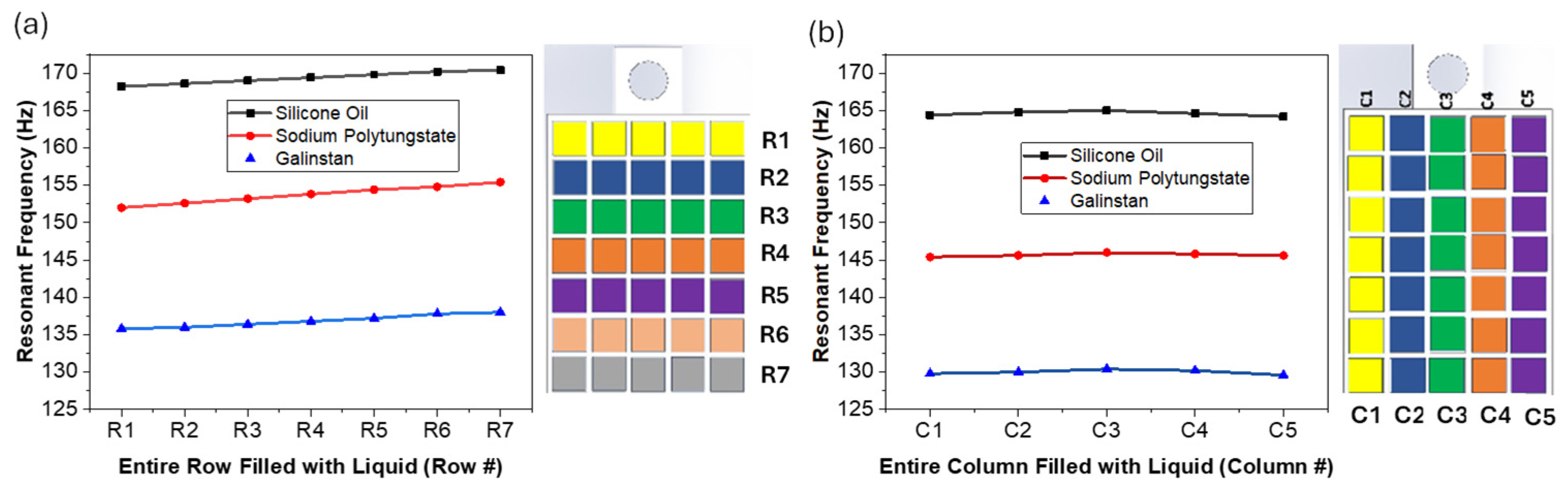
3.2. Tuning Resolution

MEMS energy harvesting devices have a narrow bandwidth of 1–3 Hz, which is approximately 1% of the resonant frequency. Therefore, to maximize output voltage, the tuning resolution needs to be less than the bandwidth and ideally in the sub Hz range. To demonstrate the potential achievable frequency tuning resolution, individual cavities in the 5 × 7 array were filled with different liquids. The results of filling individual cavities with 100% volume along the middle column are shown in Figure 4a. When the free-end cavity (C31) was filled, the changes in frequency were 35 Hz, 45 Hz, and 56.4 Hz for silicone oil, sodium polytungstate, and Galinstan, respectively, while filling the cavity along the same column but at the tethered end (C37) resulted in a change in frequency of 31 Hz, 41 Hz, and 52.4 Hz, respectively. The slope of each of these curves is nearly identical, with values of 0.667, 0.671, and 0.664 for silicone oil, sodium polytungstate, and Galinstan, where the slope is given as the frequency/cavity number. Therefore, given the cavity size, 3 × 3 mm with a 0.5 mm spacing between individual cavities along the middle column will alter the frequency by 0.66 Hz per cavity. The gradient matches well with the theoretical value obtained in Equation (2), which for the given structure would have a slope of 0.61 Hz/cavity. As expected from Equation (2), as the center of gravity shifts toward the free end, the change in resonant frequency is greater, and the more mass in the cavity also significantly reduces the frequency.
Next, we wanted to determine how altering the mass along a row (laterally) would affect the frequency, so we filled individual cavities along the middle row (row 4). When the cavities in the middle row (Ri4), where i is the various columns in the array, were filled with liquid, the frequency decreased due to the mass being added, but no significant difference was illustrated due to the location, as shown in Figure 4b. Adding mass to the middle row caused the frequency to reduce from 217 Hz to averages of 183.4, 173.6, and 161.7 Hz for silicone oil, sodium polytungstate, and Galinstan, respectively. However, the standard deviation across the row was less than 0.4 Hz for all liquids. Thus, it is shown that filling lateral cavities reduces the resonant frequency but only due to changing the overall mass, but changing the lateral center of gravity had almost no effect on the resonant frequency. Therefore, filling lateral cavities can be used to finely tune the resonant frequency, which can aid in achieving sub Hz resolution by filling lateral cavities with liquids of varying volume and density.
Next, we wanted to determine the effects of filling entire rows and columns, but we only filled a single row or column at one time, and the results are shown in Figure 5a,b. Row 1 (R1), toward the free end, demonstrated a decrease in resonant frequency to 168.2 Hz, 152 Hz, and 135.4 Hz for silicone oil, sodium polytungstate, and Galinstan, respectively, while filling the row at the tethered end (R7) resulted in a resonant frequency of 170.4 Hz, 155.4 Hz, and 138 Hz, respectively. The frequency was significantly reduced by filling the entire row versus an individual cavity, and the density of the liquid also had significant impact. However, the reduction in frequency was mostly due to the overall mass, as altering the location along the cantilever only had a slight change with slopes of 0.38, 0.564, and 0.393 Frequency/R#, which represent the resolutions that can be achieved with each liquid.
For when the columns (Cn) were filled, where n is the number of the column, the results are shown in Figure 5b. The results show a significant decrease in resonant frequency due to the mass change. The frequency decreased more than when filling the rows because there were seven cavities per column and only five per row. However, there was no significant change in resonant frequency due to location of the column, which agrees with the results shown for the individual cavities in Figure 4b. The results illustrate that filling cavities along the row significantly alters the frequency due to both mass and location, whereas filling lateral cavities only affects the frequency due to mass, which agrees with Equation (2).
After determining the impact of filling individual rows and columns, we investigated the impact of filling consecutive rows and columns, and the results are shown in Figure 6a (rows) and Figure 6b (columns). For the rows, we started with filling R1 and then proceeded until R1–7 were filled. In filling consecutive rows, the mass increases significantly, which resulted in a significant decrease in resonant frequency. When all the rows were filled, the results were similar to those shown in Figure 2 for each of the liquids. The slope of the curves of all three liquids were −4.46, −7.28, and −9.57 resonant frequency/rows for silicone oil, sodium polytungstate, and Galinstan. This illustrates that filling a consecutive row can alter the resonant frequency by 4.46–9.57 Hz, depending on the liquid, where Galinstan (a denser liquid) had a larger impact. The repeatability of this is based on the repeatability of filling the cavities, which when using a liquid dispensing system can be well controlled, thus resulting in excellent repeatability. The results in Figure 6b illustrate frequency changes for filling consecutive columns, which resulted in similar trendlines as filling the rows, due to the lateral location having little impact on the reduction in the frequency, as demonstrated above.
The resonant frequency of the cantilever also changes if we change the dimensions of the proof mass, as this affects the overall proof mass and the amount of liquid that can be used. To illustrate this, we fabricated proof masses with varying heights (7.5 mm, 10 mm, and 15 mm) while keeping the array dimensions the same, and then we filled the cavities with Galinstan. This essentially had effects similar to changing the volume of the liquid, but it also influenced the initial frequency as it changed the initial proof mass. The frequency ranges obtained were 104.2–260 Hz (Δ155.8 Hz), 78.4–217 Hz (Δ138.6 Hz), and 32.4–183 Hz (Δ150.6 Hz), respectively.

4. Conclusions

In conclusion, this paper demonstrates a novel method of passively tuning the resonant frequency of a rectangular piezoelectric cantilever by creating a proof mass with an array of empty chambers or cavities and filling them with liquid. This concept could be easily integrated into the fabrication process, where a single device could be fabricated with a high resonant frequency and then tuned post processing by filling individual cavities. Ultimately, a library could be created so that customers could request a specific resonant frequency and AI robotics could fill specific cavities to meet the specifications of customers. In altering the density or the liquids used, the filling volume, and the location, one could tune the frequency with a >100 Hz range and with sub Hz resolution. In this study, we only used a single liquid when filling an entire row or column, but in practice, one could fill some cavities with silicone oil and some with Galinstan or other liquids. In carrying this out, there are an infinite number of combinations that could be used to achieve specific tuning capabilities. When the cavity was completely filled, the fluid in the cavity was stable, but if the cavity was only partially filled, the fluid could have sloshing effects, which could be used to increase the bandwidth. A method for overcoming sloshing effects would be to use a parylene capping layer after filling, which would eliminate any stability issues or leakage issues with the fluid [56].
This study only investigated a 5 × 7 array proof mass with specific cavity dimensions of 3 × 3 mm with a spacing of 0.5 mm; however, to further increase the tuning range, we would need to reduce the initial proof mass and increase the total amount of fluid that can be added. On the other hand, there are multiple methods with which to increase precision, such as increasing the array size and lowering the size of each cavity, administering liquids of different densities, and altering the amount inserted into each cavity. Other methods with which to enhance the tuning performance could be achieved by removing the screw required to bond the proof mass to the cantilever and also by removing the 3D printed capping layer using a thin film parylene capping layer. All of these methods were investigated using macro-scale devices, but the concept should be applied to micro-scale devices. However, the major challenge with MEMS devices would be controlling the filling volumes. In addition, the concept was validated with a rectangular cantilever, but the concept should theoretically work with other shapes such as trapezoidal and even circular membranes, so the concept could be applied to other tuning devices such as RF MEMSs and ultrasound transducers. In addition, the concept could be applied to other structures and with various dimensions ranging from the macro to micro scale.

5. Patents

Part of the work in this study is based on US Patent 2024 63/672513.

Author Contributions

R.A. was responsible for investigation, writing—original draft or the paper, and validation. N.J. was responsible for conceptualization, supervision, editing drafts of the paper, and funding acquisition. All authors have read and agreed to the published version of the manuscript.

Funding

The research was funded by the National Science Foundation’s NSF CAREER program, grant number 2237086.

Data Availability Statement

The data presented in this study are available on request from the corresponding author. The data are not publicly available due to privacy.

Acknowledgments

The authors would like to thank their fellow colleagues of the SMART Lab at the University of New Mexico.

Conflicts of Interest

The authors declare no conflicts of interest.

References

  1. Iqbal, M.; Nauman, M.M.; Khan, F.U.; Abas, P.E.; Cheok, Q.; Iqbal, A.; Aissa, B. Vibration-based piezoelectric, electromagnetic, and hybrid energy harvesters for microsystems applications: A contributed review. Int. J. Energy Res. 2020, 45, 65–102. [Google Scholar] [CrossRef]
  2. Vocca, H.; Cottone, F. Kinetic energy harvesting. In ICT-Energy-Concepts Towards Zero-Power Information and Communication Technology; IntechOpen: London, UK, 2014. [Google Scholar]
  3. Pan, H.; Qi, L.; Zhang, Z.; Yan, J. Kinetic energy harvesting technologies for applications in land transportation: A comprehensive review. Appl. Energy 2021, 286, 116518. [Google Scholar] [CrossRef]
  4. Sue, C.-Y.; Tsai, N.-C. Human powered MEMS-based energy harvest devices. Appl. Energy 2012, 93, 390–403. [Google Scholar] [CrossRef]
  5. Iannacci, J. Microsystem based Energy Harvesting (EH-MEMS): Powering pervasivity of the Internet of Things (IoT)–A review with focus on mechanical vibrations. J. King Saud Univ.-Sci. 2019, 31, 66–74. [Google Scholar] [CrossRef]
  6. Han, M.; Wang, H.; Yang, Y.; Liang, C.; Bai, W.; Yan, Z.; Li, H.; Xue, Y.; Wang, X.; Akar, B.; et al. Three-dimensional piezoelectric polymer microsystems for vibrational energy harvesting, robotic interfaces and biomedical implants. Nat. Electron. 2019, 2, 26–35. [Google Scholar] [CrossRef]
  7. Pulskamp, J.S.; Polcawich, R.G.; Rudy, R.Q.; Bedair, S.S.; Proie, R.M.; Ivanov, T.; Smith, G.L. Piezoelectric PZT MEMS technologies for small-scale robotics and RF applications. MRS Bull. 2012, 37, 1062–1070. [Google Scholar] [CrossRef]
  8. Ding, J.; Challa, V.R.; Prasad, M.G.; Fisher, F.T. Vibration energy harvesting and its application for nano-and microrobotics. In Selected Topics in Micro/Nano-Robotics for Biomedical Applications; Springer: New York, NY, USA, 2013; pp. 59–83. [Google Scholar]
  9. Jackson, N.; Olszewski, O.Z.; O’murchu, C.; Mathewson, A. Shock-induced aluminum nitride based MEMS energy harvester to power a leadless pacemaker. Sens. Actuators A Phys. 2017, 264, 212–218. [Google Scholar] [CrossRef]
  10. Liu, Y.; Hu, B.; Cai, Y.; Zhou, J.; Liu, W.; Tovstopyat, A.; Wu, G.; Sun, C. Design and performance of ScAlN/AlN trapezoidal cantilever-based MEMS piezoelectric energy harvesters. IEEE Trans. Electron Devices 2021, 68, 2971–2976. [Google Scholar] [CrossRef]
  11. Song, H.-C.; Kumar, P.; Maurya, D.; Kang, M.-G.; Reynolds, W.T.; Jeong, D.-Y.; Kang, C.-Y.; Priya, S. Ultra-low resonant piezoelectric MEMS energy harvester with high power density. J. Microelectromech. Syst. 2017, 26, 1226–1234. [Google Scholar] [CrossRef]
  12. Todaro, M.T.; Guido, F.; Mastronardi, V.; Desmaele, D.; Epifani, G.; Algieri, L.; De Vittorio, M. Piezoelectric MEMS vibrational energy harvesters: Advances and outlook. Microelectron. Eng. 2017, 183, 23–36. [Google Scholar] [CrossRef]
  13. Nisanth, A.; Suja, K.J.; Seena, V. Design and optimization of MEMS piezoelectric energy harvester for low frequency applications. Microsyst. Technol. 2021, 27, 251–261. [Google Scholar] [CrossRef]
  14. Dompierre, A.; Keshavarzi, M.; Amnache, A.; Fréchette, L.G. Demonstration of Low Frequency and High-Power Density Aln-Based Piezoelectric Vibration Energy Harvesters Using High Density Tungsten Proof Masses. In Proceedings of the 2024 IEEE 23rd International Conference on Micro and Miniature Power Systems, Self-Powered Sensors and Energy Autonomous Devices (PowerMEMS), Tonsberg, Norway, 18–21 November 2024; IEEE: Piscataway, NJ, USA, 2024. [Google Scholar]
  15. Liu, H.; Tay, C.J.; Quan, C.; Kobayashi, T.; Lee, C. Piezoelectric MEMS energy harvester for low-frequency vibrations with wideband operation range and steadily increased output power. J. Microelectromech. Syst. 2011, 20, 1131–1142. [Google Scholar] [CrossRef]
  16. Shen, D.; Park, J.-H.; Ajitsaria, J.; Choe, S.-Y.; Wikle, H.C.; Kim, D.-J. The design, fabrication and evaluation of a MEMS PZT cantilever with an integrated Si proof mass for vibration energy harvesting. J. Micromech. Microeng. 2008, 18, 055017. [Google Scholar] [CrossRef]
  17. Jia, Y.; Seshia, A.A. Power optimization by mass tuning for MEMS piezoelectric cantilever vibration energy harvesting. J. Microelectromech. Syst. 2015, 25, 108–117. [Google Scholar] [CrossRef]
  18. Olszewski, O.Z.; Houlihan, R.; Blake, A.; Mathewson, A.; Jackson, N. Evaluation of vibrational PiezoMEMS harvester that scavenges energy from a magnetic field surrounding an AC current-carrying wire. J. Microelectromech. Syst. 2017, 26, 1298–1305. [Google Scholar] [CrossRef]
  19. Liang, H.; Hao, G.; Olszewski, O.Z. A review on vibration-based piezoelectric energy harvesting from the aspect of compliant mechanisms. Sens. Actuators A Phys. 2021, 331, 112743. [Google Scholar] [CrossRef]
  20. Elfrink, R.; Renaud, M.; Kamel, T.M.; de Nooijer, C.; Jambunathan, M.; Goedbloed, M.; Hohlfeld, D.; Matova, S.; Pop, V.; Caballero, L.; et al. Vacuum-packaged piezoelectric vibration energy harvesters: Damping contributions and autonomy for a wireless sensor system. J. Micromech. Microeng. 2010, 20, 104001. [Google Scholar] [CrossRef]
  21. Kamel, T.M.; Elfrink, R.; Renaud, M.; Hohlfeld, D.; Goedbloed, M.; de Nooijer, C.; Jambunathan, M.; van Schaijk, R. Modeling and characterization of MEMS-based piezoelectric harvesting devices. J. Micromech. Microeng. 2010, 20, 105023. [Google Scholar] [CrossRef]
  22. Jackson, N. PiezoMEMS Nonlinear Low Acceleration Energy Harvester with an Embedded Permanent Magnet. Micromachines 2020, 11, 500. [Google Scholar] [CrossRef]
  23. Hossain, I.; Zahid, S.; Chowdhury, M.A.; Hossain, M.M.M.; Hossain, N. MEMS-based energy harvesting devices for low-power applications—A review. Results Eng. 2023, 19, 101264. [Google Scholar] [CrossRef]
  24. Ferrari, M.; Ferrari, V.; Guizzetti, M.; Andò, B.; Baglio, S.; Trigona, C. Improved energy harvesting from wideband vibrations by nonlinear piezoelectric converters. Sens. Actuators A Phys. 2010, 162, 425–431. [Google Scholar] [CrossRef]
  25. Hajati, A.; Kim, S.-G. Ultra-wide bandwidth piezoelectric energy harvesting. Appl. Phys. Lett. 2011, 99, 083105. [Google Scholar] [CrossRef]
  26. Kim, T.; Ko, Y.; Yoo, C.; Choi, B.; Han, S.; Kim, N. Design optimisation of wide-band piezoelectric energy harvesters for self-powered devices. Energy Convers. Manag. 2020, 225, 113443. [Google Scholar] [CrossRef]
  27. Halim, M.A.; Khym, S.; Park, J.Y. Frequency up-converted wide bandwidth piezoelectric energy harvester using mechanical impact. J. Appl. Phys. 2013, 114, 044902. [Google Scholar] [CrossRef]
  28. Halim, M.A.; Park, J.Y. Theoretical modeling and analysis of mechanical impact driven and frequency up-converted piezoelectric energy harvester for low-frequency and wide-bandwidth operation. Sens. Actuators A Phys. 2014, 208, 56–65. [Google Scholar] [CrossRef]
  29. Jackson, N. Secondary Impact bandwidth effects using Embedded Vertical Moving Mass Energy Harvester. In Proceedings of the 2021 IEEE 20th International Conference on Micro and Nanotechnology for Power Generation and Energy Conversion Applications (PowerMEMS), Exeter, UK, 6–8 December 2021; IEEE: Piscataway, NJ, USA, 2021. [Google Scholar]
  30. Rosso, M.; Ardito, R. A Review of Nonlinear Mechanisms for Frequency Up-Conversion in Energy Harvesting. Actuators 2023, 12, 456. [Google Scholar] [CrossRef]
  31. Amini, Y.; Heshmati, M.; Fatehi, P.; Habibi, S.E. Energy harvesting from vibrations of a functionally graded beam due to moving loads and moving masses. J. Eng. Mech. 2017, 143, 04017063. [Google Scholar] [CrossRef]
  32. Jackson, N.; Rodriguez, L.A.; Adhikari, R. Wide bandwidth vibration energy harvester with embedded transverse movable mass. Sensors 2021, 21, 5517. [Google Scholar] [CrossRef] [PubMed]
  33. Jackson, N.; Stam, F. Sloshing liquid-metal mass for widening the bandwidth of a vibration energy harvester. Sens. Actuators A Phys. 2018, 284, 17–21. [Google Scholar] [CrossRef]
  34. Jackson, N.; Stam, F.; Olszewski, O.Z.; Doyle, H.; Quinn, A.; Mathewson, A. Widening the bandwidth of vibration energy harvesters using a liquid-based non-uniform load distribution. Sens. Actuators A Phys. 2016, 246, 170–179. [Google Scholar] [CrossRef]
  35. Mohanty, A.; Behera, R.K. Energy Harvesting from a Cantilever Beam with Geometric Nonlinearity Subjected to a Moving Mass. Arab. J. Sci. Eng. 2022, 47, 16393–16408. [Google Scholar] [CrossRef]
  36. Shi, G.; Yang, Y.; Chen, J.; Peng, Y.; Xia, H.; Xia, Y. A broadband piezoelectric energy harvester with movable mass for frequency active self-tuning. Smart Mater. Struct. 2020, 29, 055023. [Google Scholar] [CrossRef]
  37. Somkuwar, R.; Chandwani, J.; Deshmukh, R. Bandwidth widening of piezoelectric energy harvester by free moving cylinders in liquid medium. Microsyst. Technol. 2021, 27, 1959–1970. [Google Scholar] [CrossRef]
  38. Salem, M.S.; Ahmed, S.; Shaker, A.; Alshammari, M.T.; Al-Dhlan, K.A.; Alanazi, A.; Saeed, A.; Abouelatta, M. Bandwidth broadening of piezoelectric energy harvesters using arrays of a proposed piezoelectric cantilever structure. Micromachines 2021, 12, 973. [Google Scholar] [CrossRef]
  39. Jackson, N.; Kumar, K.; Olszewski, O.; Schenning, A.P.H.J.; Debije, M.G. Tuning MEMS cantilever devices using photoresponsive polymers. Smart Mater. Struct. 2019, 28, 085024. [Google Scholar] [CrossRef]
  40. Lallart, M.; Anton, S.R.; Inman, D.J. Frequency self-tuning scheme for broadband vibration energy harvesting. J. Intell. Mater. Syst. Struct. 2010, 21, 897–906. [Google Scholar] [CrossRef]
  41. Al-Ashtari, W.; Hunstig, M.; Hemsel, T.; Sextro, W. Frequency tuning of piezoelectric energy harvesters by magnetic force. Smart Mater. Struct. 2012, 21, 035019. [Google Scholar] [CrossRef]
  42. Anand, A.; Pal, S.; Kundu, S. Bandwidth and power enhancement in the MEMS-based piezoelectric energy harvester using magnetic tip mass. Bull. Pol. Acad. Sci. Tech. Sci. 2022, 70, e137509. [Google Scholar] [CrossRef]
  43. Bouhedma, S.; Zheng, Y.; Lange, F.; Hohlfeld, D. Magnetic frequency tuning of a multimodal vibration energy harvester. Sensors 2019, 19, 1149. [Google Scholar] [CrossRef]
  44. Xia, H.; Chen, R.; Ren, L. Parameter tuning of piezoelectric–electromagnetic hybrid vibration energy harvester by magnetic force: Modeling and experiment. Sens. Actuators A Phys. 2017, 257, 73–83. [Google Scholar] [CrossRef]
  45. Liu, X.; He, L.; Liu, R.; Hu, D.; Zhang, L.; Cheng, G. Piezoelectric energy harvesting systems using mechanical tuning techniques. Rev. Sci. Instrum. 2023, 94, 031501. [Google Scholar] [CrossRef] [PubMed]
  46. Rivadeneyra, A.; Soto-Rueda, J.M.; O’keeffe, R.; Banqueri, J.; Jackson, N.; Mathewson, A.; López-Villanueva, J.A. Tunable MEMS piezoelectric energy harvesting device. Microsyst. Technol. 2016, 22, 823–830. [Google Scholar] [CrossRef]
  47. Song, H.; Kim, S.; Kim, H.S.; Lee, D.; Kang, C.; Nahm, S. Piezoelectric energy harvesting design principles for materials and structures: Material figure-of-merit and self-resonance tuning. Adv. Mater. 2020, 32, e2002208. [Google Scholar] [CrossRef]
  48. Kouritem, S.A.; Al-Moghazy, M.A.; Noori, M.; Altabey, W.A. Mass tuning technique for a broadband piezoelectric energy harvester array. Mech. Syst. Signal Process. 2022, 181, 109500. [Google Scholar] [CrossRef]
  49. Adhikari, R.; Jackson, N. Passive Frequency Tuning of Piezoelectric Energy Harvester using Embedded Masses. In Proceedings of the 2021 IEEE 20th International Conference on Micro and Nanotechnology for Power Generation and Energy Conversion Applications (PowerMEMS), Exeter, UK, 6–8 December 2021; IEEE: Piscataway, NJ, USA, 2021. [Google Scholar]
  50. Adhikari, R.; Jackson, N. Passively Tuning the Resonant Frequency of Kinetic Energy Harvesters Using Distributed Loaded Proof Mass. Appl. Sci. 2023, 14, 156. [Google Scholar] [CrossRef]
  51. Shaikh, F.K.; Zeadally, S. Energy harvesting in wireless sensor networks: A comprehensive review. Renew. Sustain. Energy Rev. 2016, 55, 1041–1054. [Google Scholar] [CrossRef]
  52. Efimovskaya, A.; Wang, D.; Shkel, A.M. Mechanical trimming with focused ion beam for permanent tuning of MEMS dual-mass gyroscope. Sens. Actuators A Phys. 2020, 313, 112189. [Google Scholar] [CrossRef]
  53. Abdelmoneum, M.; Demirci, M.; Lin, Y.-W.; Nguyen, C.-C. Location-dependent frequency tuning of vibrating micromechanical resonators via laser trimming. In Proceedings of the 2004 IEEE International Frequency Control Symposium and Exposition, Montreal, QC, Canada, 23–27 August 2004; IEEE: Piscataway, NJ, USA, 2004. [Google Scholar]
  54. Somkuwar, R.; Chandwani, J.; Deshmukh, R. Wideband auto-tunable vibration energy harvester using change in centre of gravity. Microsyst. Technol. 2018, 24, 3033–3044. [Google Scholar] [CrossRef]
  55. Adhikari, R.; Karimi, V.; Jackson, N. Passive Frequency Tuning Using Liquid Distributed Load. In Proceedings of the ASME 2023 International Mechanical Engineering Congress and Exposition, New Orleans, LA, USA, 29 October–2 November 2023. [Google Scholar]
  56. Adhikari, R.; Jackson, N. Parylene Capping Layer for Embedded Liquid Mass for MEMS Packaging. In Proceedings of the ASME 2024 International Mechanical Engineering Congress and Exposition, Portland, OR, USA, 17–21 November 2024. American Society of Mechanical Engineers Digital Collection. [Google Scholar]
  57. Zhao, B.; Xu, T.-B. Finite Element Modelling and Experimental Validations of Proof Mass Effects on Flextensional Piezoelectric Energy Harvesters. Sens. Actuators A Phys. 2025, 383, 116185. [Google Scholar] [CrossRef]
Figure 1. (a) Schematic of 5 × 7 proof mass on cantilever with cavities C54 and C52 filled with liquid; (b) top-view schematic of proof mass on cantilever with nomenclature of its rows and columns; and (c) experimental piezoelectric cantilever with 3D printed proof mass on vibration shaker.
Actuators 14 00078 g001
Figure 2. (a) Experimental results illustrating Vpp as a function of frequency with various liquids with all 100% cavities filled and an empty control mass; (b) Vpp as a function of frequency with all cavities filled to 25%, 50%, and 100% volume using sodium polytungstate.
Actuators 14 00078 g002
Figure 3. (a) Voltage as a function of frequency for all cavities filled with varying volumes of liquids; (b) results illustrating the 1st resonant frequency mode as a function of filling an individual cavity along a middle column with 25%, 50%, 75%, and 100% liquid sodium polytungstate (change in frequency illustrated in parenthesis); and (c) schematic illustrating the individual cavities filled.
Actuators 14 00078 g003
Figure 4. (a) First resonant frequency mode as a function of filling an individual cavity along the middle column with various liquids; (b) first resonant frequency mode as a function of filling an individual cavity along the middle row with various liquids (each cavity was filled 100%).
Actuators 14 00078 g004
Figure 5. First resonant frequency mode as a function of filling individual rows and columns with varying liquids (a) along individual rows and (b) along individual columns.
Actuators 14 00078 g005
Figure 6. First resonant frequency mode as a function of filling consecutive cavities with varying liquids (a) along consecutive rows and (b) along consecutive columns.
Actuators 14 00078 g006
Disclaimer/Publisher’s Note: The statements, opinions and data contained in all publications are solely those of the individual author(s) and contributor(s) and not of MDPI and/or the editor(s). MDPI and/or the editor(s) disclaim responsibility for any injury to people or property resulting from any ideas, methods, instructions or products referred to in the content.

