Article

Dynamic Modelling and Experimental Investigation of an Active–Passive Variable Stiffness Actuator

1
College of Mechanical and Electrical Engineering, Zhengzhou University of Light Industry, Zhengzhou 450001, China
2
Henan Provincial Key Laboratory of Intelligent Manufacturing of Mechanical Equipment, Zhengzhou 450001, China
*
Author to whom correspondence should be addressed.
Actuators 2025, 14(4), 169; https://doi.org/10.3390/act14040169
Submission received: 10 February 2025 / Revised: 26 March 2025 / Accepted: 27 March 2025 / Published: 29 March 2025
(This article belongs to the Section Actuator Materials)

Abstract

:
To overcome the limitations imposed by the low flexible angle of conventional robots, an active–passive variable stiffness elastic actuator (APVSA) is investigated and a nonlinear dynamic model for the APVSA is established, considering the factors of the moment of inertia, stiffness and damping of elastic elements, meshing stiffness of gear systems, nonlinear backlash, nonlinear meshing damping, and comprehensive transmission error. The established dynamic model is discretized by the forward Euler method, and the variable stiffness performance and the influence of nonlinear factors on the APVSA are analysed by Adams and Simulink simulations, respectively. A physical prototype and an experimental platform were assembled, and the dynamic and static variable stiffness experiments were conducted. The experimental results realized the expected stiffness adjustment target and provided the foundation for the next step of control.

1. Introduction

With the improvement of science and technology, robotics are widely used. Especially in the field of industrial processing and manufacturing, robots are used for different purposes, such as welding, spraying, and loading and unloading [1,2,3]. Traditional industrial robots for task activities are fixed, and perform a high number of repetitive tasks; with development over time, robots need further human–robot interaction, and the traditional robots no longer satisfy the needs of the current era [4,5].
For traditional robots, the joints of traditional rigid robots usually adopt a rigid connection design, which leads to potential safety risks in the process of human–machine collaboration. When a robot encounters an interactive object unexpectedly, the rigid connection structure may cause mechanical damage to the operator or the environment, thus limiting the robot’s application ability in autonomous operation and human–machine collaboration scenarios [6,7,8,9].
Traditional rigid robots are typically designed to employ a motor combined with a reducer structure for adjusting the stiffness of joints, where the input torque is directly amplified by the reducer and transmitted to the load. So, the stiffness is purely rigid, resulting in low compliance and making it unsuitable for human–robot interaction scenarios [10,11,12]. For solving this problem, passive actuators can be used. They are designed to incorporate an elastic element in series between the driving motor and the load. While the stiffness is reduced, it remains constant. However, the response speed is relatively slow since the torque transmission needs to pass through the elastic element [13,14,15]. Active variable stiffness actuators can also be used for improving the stiffness of the joints of robots; they introduce a variable stiffness mechanism, allowing flexible switching between high and low stiffness. However, due to the lack of elastic elements, the compliance of the actuator remains relatively low [16,17,18,19].
A variable stiffness elastic actuator (VSA) is proposed and widely used in the field of robots. Because its stiffness can be adjusted in real time, the variable stiffness elastic actuator can drive the robot as a flexible joint, thus significantly improving the safety and adaptability of the robot in human–machine collaboration.
Based on the principles of variable stiffness mechanisms, variable stiffness actuators are classified into four categories. ① Antagonistic type. The antagonistic variable stiffness mechanism is inspired by the human antagonist–primary actuator drive model. Petit et al. [20] proposed a bi-directional antagonistic VSA (BAVS) and applied it to the wrist and brachioradial joints of the DLR robotic arm; Liu et al. [21] proposed a rope-driven antagonistic VSA (SPVSA) based on the principle of spring-parallelism, which improves the efficiency of energy storage and reduces the size and weight at the same time. ② Variable spring-preload type. Li et al. [22] proposed a variable spring preload type VSA (CVSA) using a rope-pulley set actuation, which allows for varying the number of springs to achieve different stiffness ranges; Ji et al. [23] proposed a VSA based on a cam-roller-spring mechanism (SDS-VSA) with a symmetric compression spring structure, which improves the output torque and range of stiffness variation in variable-stiffness joints. ③ Variable-lever type. Based on the lever principle, the magnitude of the output moment and stiffness of the VSA is varied by changing the position of the pivot point or the spring assembly or the input force on the lever arm. Sarani et al. [24] proposed a variable pivot point position-type VSA (VSAPLM) for lower limb rehabilitation robots, which uses a four-link to change the position of the lever pivot point, with a maximum theoretical stiffness of positive infinity. Miha et al. [25] proposed a rotating cam-based variable spring assembly The overall mechanism is compact and suitable for humanoid robots. Li et al. [26] proposed a kind of VSA suitable for variable input force position, characterized by high stiffness adjustment accuracy and wide range. ④ Variable spring physical parameter type. According to the principle of material mechanics, the stiffness of the elastic element is changed. Xu et al. [27] proposed a reconfigurable VSA (RVSA) based on an S-shaped spring, realizing stepless regulation from low rigidity to almost complete rigidity. Researchers at home and abroad have provided abundant research results on variable stiffness actuators. However, the common variable stiffness actuators are usually passive or active type alone, and the related research on active–passive composite variable stiffness actuators is relatively small, so the active plus passive VSA may become a new trend in the field of robotics.
In order to realize the precise control of a VSA, it is necessary to establish an accurate dynamics model of a VSA, and the dynamics model of more complex structures contains many complex and difficult to clarify but required inherent nonlinear laws and parameters. Zhu et al. [28] proposed a hybrid nonlinear identification method to identify nonlinear stiffness and damping for the nonlinear behaviour associated with stiffness and damping in engineering structures. Hu et al. [29] proposed a simultaneous identification algorithm to identify the backlash value and effective stiffness parameters simultaneously for nonlinear factors such as backlash, which are difficult to avoid in engineering. Ting et al. [30] have developed a Bayesian parameter identification method to address the difficulties and inaccuracies in identifying general methods for rigid body dynamics models based on CAD data and driver models. Zhou et al. [31] used a particle swarm optimization (PSO) method to identify the model parameters in order to obtain an accurate linear model of the actuator and to realize the state and parameter estimation of the shift actuator of an electric bus.
In the preliminary study [32], a variable lever type active–passive composite variable stiffness actuator (APVSA) is presented. The variable stiffness principle of the APVSA is described in detail, and the strength analysis is carried out by using Ansys for the planetary gears. The variable stiffness experiments, dynamic motion experiments, ball-throwing experiments, static experiments of impact resistance, and dynamic experiments of impact resistance are simulated by using Adams. The results show that it can achieve the required performance in future applications, like humanoid robots, quadrupedal robots, and collaborative robots.
According to Table 1, the APVSA has the advantages of low stiffness and a large flexible angle compared with other types of VSAs, and stiffness values can be adjusted while enhancing safety, which has a broad application prospect in the field of human–robot interaction such as for collaborative robots and exoskeletal rehabilitation-assisted robots.
Based on the previous research [32], in this paper, the nonlinear dynamics modelling of an APVSA is presented from input to output by considering the rotational inertia, stiffness and damping of the elastic element, meshing stiffness of the gear train, nonlinear tooth-side backlash, nonlinear meshing damping, and integrated transfer error. What is more, the nonlinear influencing factors of the dynamics of APVSAs are verified by using simulation and the experimental results of the dynamic and static variable stiffness are analysed.
In the second section of this paper, the structural components of APVSA are introduced, the principle of variable stiffness is explained, a nonlinear dynamics model is developed, and the dynamics model is discretized and extended. In Section 3, the APVSA and the nonlinear dynamics model are simulated and analysed using Adams 2020 and Simulink 2022 software, respectively. In Section 4, an experimental platform is built for conducting static stiffness experiments and dynamic stiffness experiments. Finally, the study is summarized and future directions are described.

2. Structural Design and Dynamic Modelling of APVSA

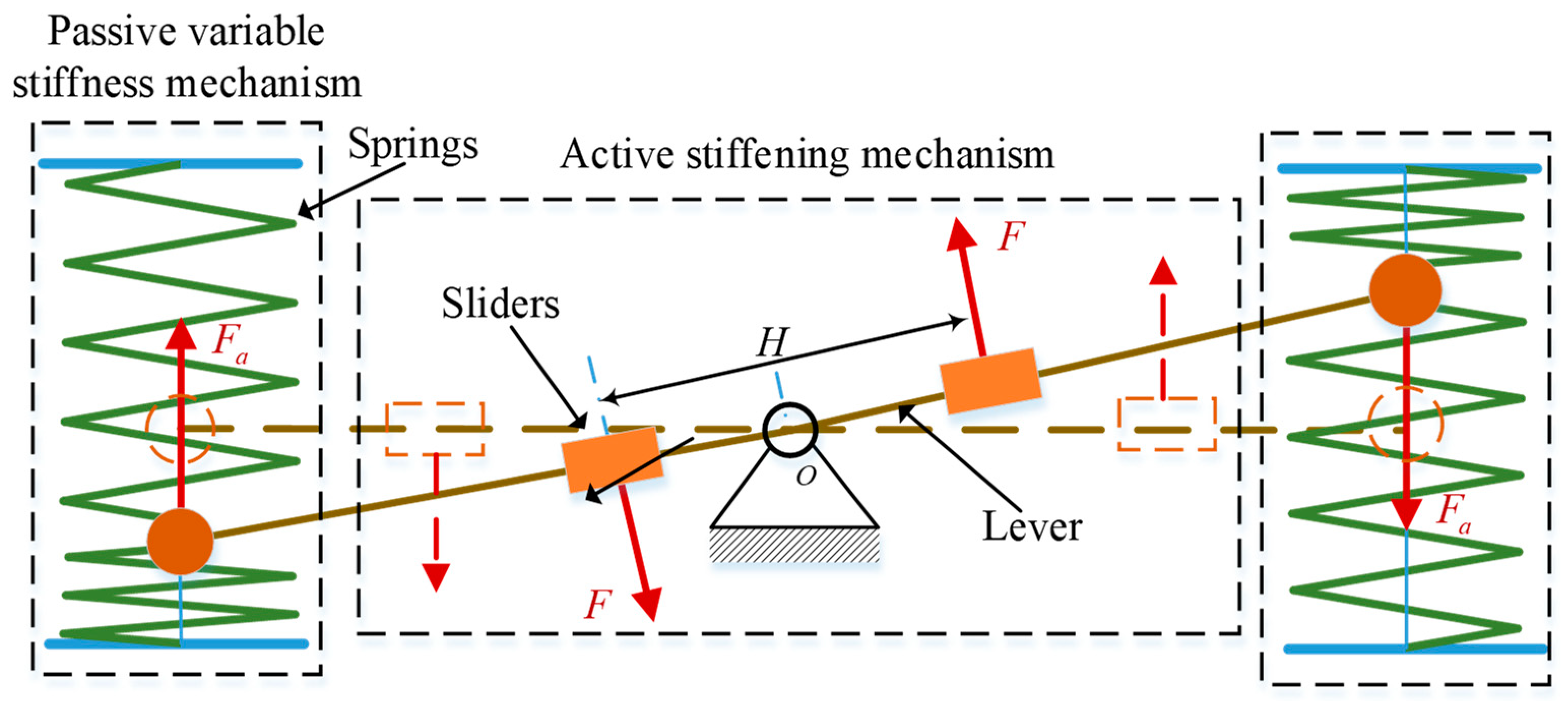
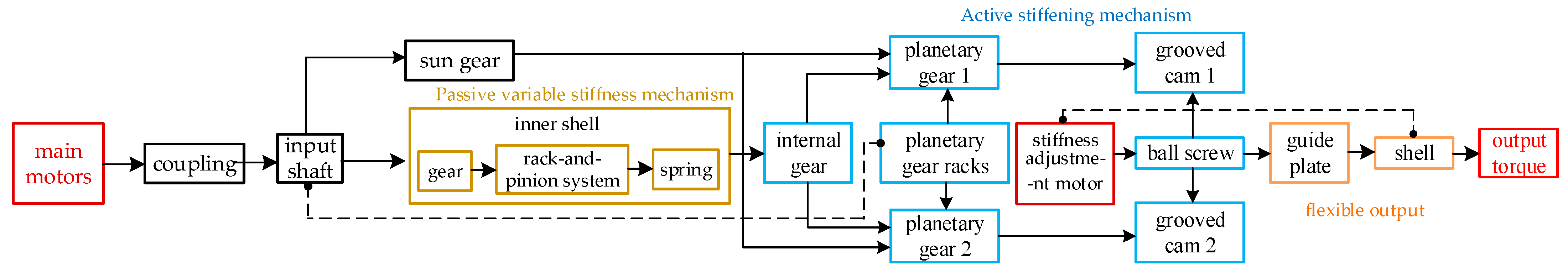
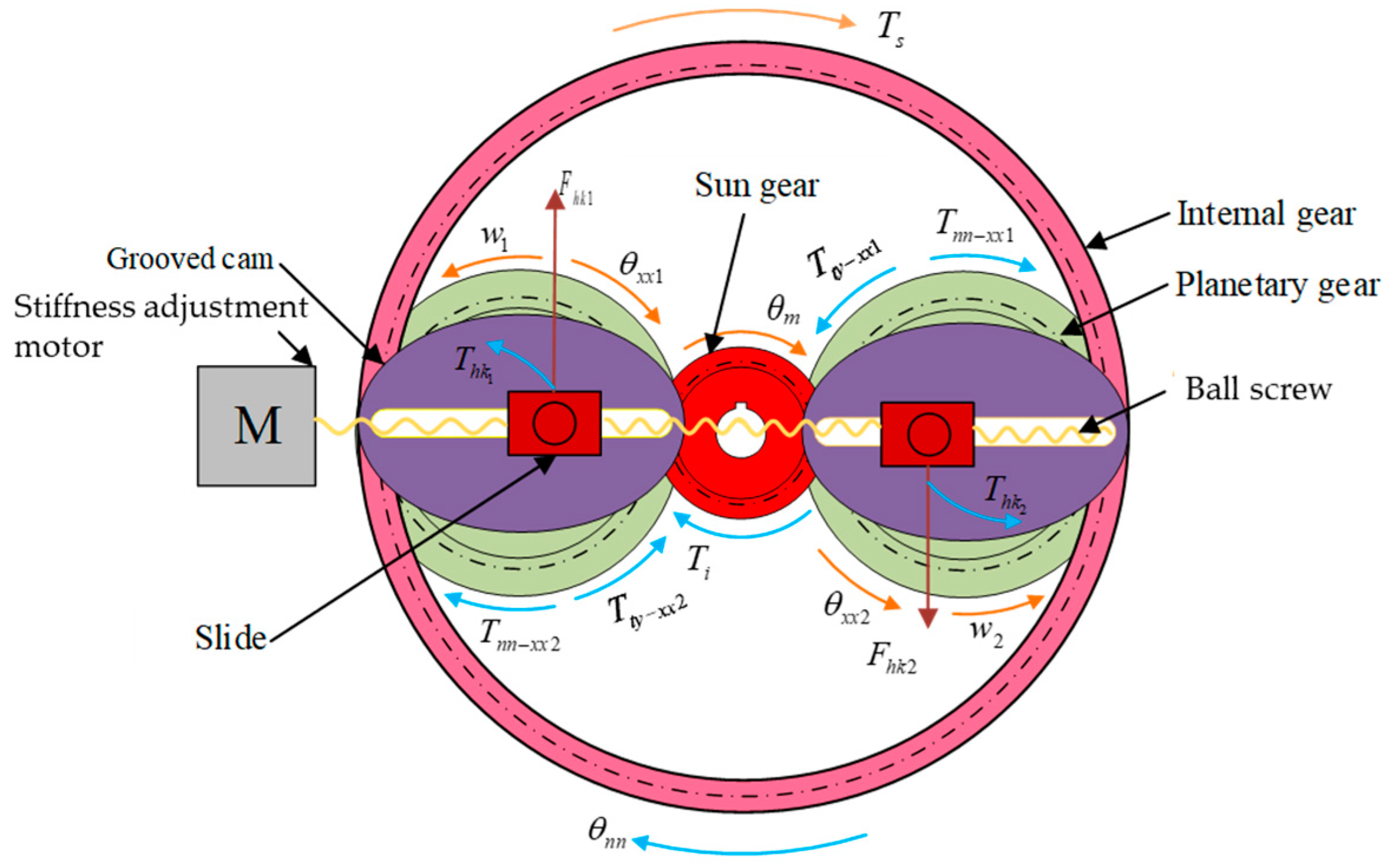
2.1. Working Principle

In this paper, a symmetrical lever structure is utilized to construct the APVSA as shown in Figure 1. The midpoint of the lever is the pivot point O. The two ends of the lever are connected to a pair of linear compression springs. F a is the load applied to the spring. Two sliders slide on the lever and are symmetrically distributed; H is the distance between the two sliders. The pivot point O is the input end, and the two symmetrical sliders are the output ends, which provide the output torque to the outside part. The dotted line is the initial position. The solid line is the current position.

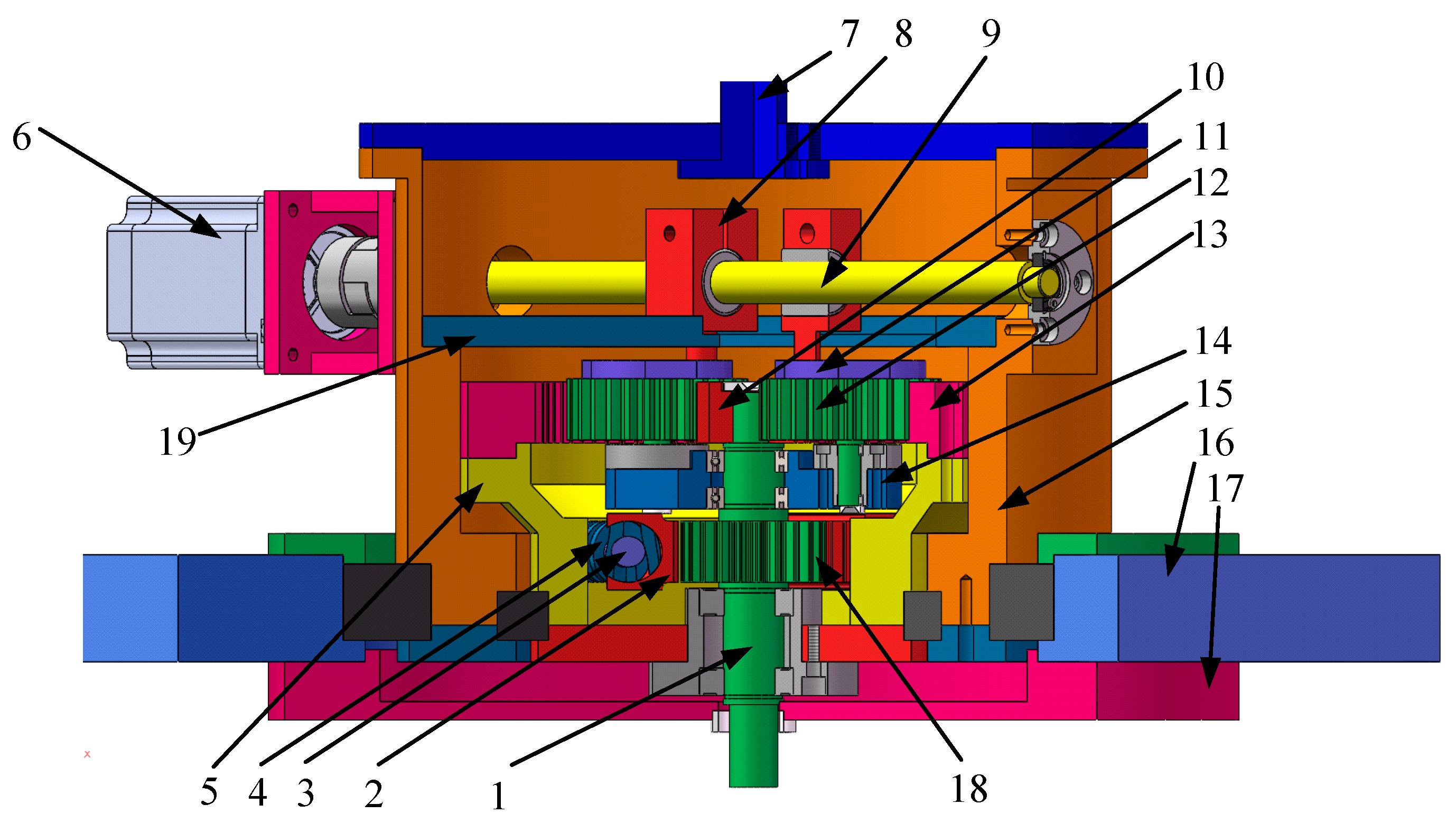
2.2. Structural Design

Unlike conventional variable lever type VSA, the APVSA adjusts stiffness by combining two types of stiffening mechanisms: a passive stiffening mechanism and an active stiffening mechanism. The stiffness adjustment is realized by adjusting the distance at which the force generated by the actuator acts, thus indirectly adjusting the ratio of torque to flexible angle at the output. The overall structure of the actuator is shown in Figure 2. In previous work [32], the structure of the APVSA was described in detail.
With the helical compression spring 4 selected, the stiffness adjustment motor 6 is used to drive the ball screw 9 to drive the slider 8 to slide in the groove of the grooved cam 11 to adjust the position of the sliders. The driving input shaft 1 drives the rack-and-pinion system 2 to compress the spring 5, and the spring pushes the inner shell 5 fixed with the internal gear, and finally acts on a set of planetary gears 12 through the internal gear. At the same time, the input shaft 1 drives the sun gear 10 through the key connection, and drives the planetary gear 12 to rotate. The power is transmitted through the grooved cams 11 fixed to the planetary gears, respectively, by means of the drive through the two sliders 8 to the guide plate 19 fixed to the shell 15, which is then transferred to the shell 15, which is fixed to the output shaft 7. Finally, the power is output from the output shaft 7 and is connected to the load. The diagram for describing torque transmission mechanism is shown in Figure 3.

2.3. Nonlinear Dynamics Modeling

According to the actuator stiffening principle, the passive variable stiffness mechanism and the active stiffness adjustment mechanism are next modelled with nonlinear dynamics, respectively.
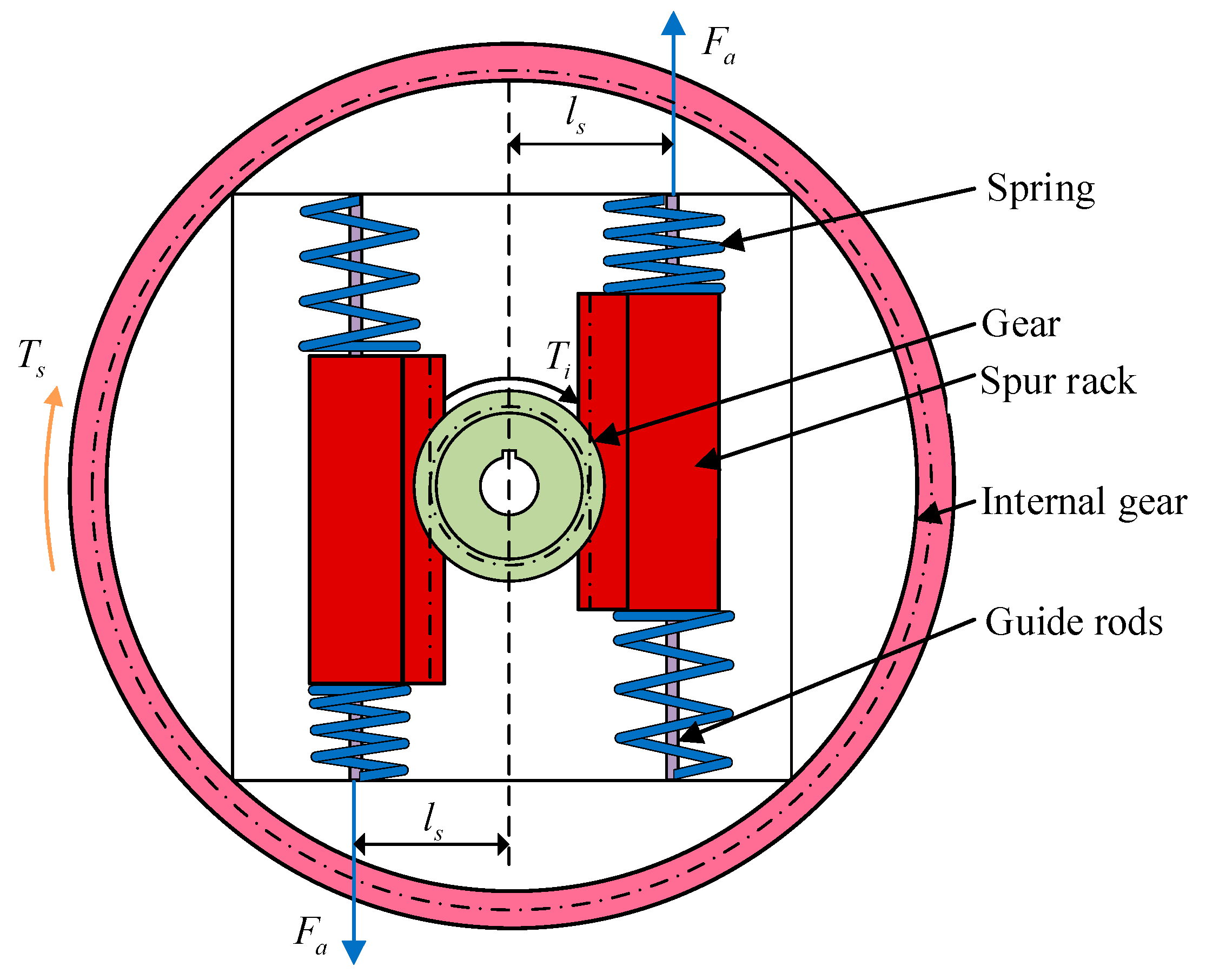
  • Passive variable stiffness mechanism
The design of the passive variable stiffness mechanism is shown in Figure 4. The symmetrical layout of the passive mechanism [36,37,38] improves the stability of the APVSA during operation. The kinetic equations are established as shown in Equation (1):
T s = 2 k r m l s θ m θ n n + B k l s r m θ ˙ m θ ˙ n n
where T s is internal gear torque, k is the stiffness of the spring, r m is the radius of the gear indexing circle, θ n n is regarded as the angle of rotation of the internal gear, and l s is the distance from the centre of the input shaft to the rack gear. The nomenclature is presented in Appendix A.
2.
Active stiffening mechanism
The active stiffening mechanism includes an internal gear, two planetary gears, a sun gear, two slotted cams, a pair of ball screws, two sliders, and an active motor, as shown in Figure 5. It also utilizes a completely symmetrical structure for overall structural stability [24,39]. The planetary gear is located between the inner gears and is driven by the combined torque T s of the first mechanism and the sun gear, which is fixed to the input shaft and driven by the input torque T i ; θ x x 1 is the angle of rotation of planetary gear 1, θ x x 2 is the angle of rotation of planetary gear 2, and θ m is the angle of rotation of the sun gear.
As shown in Figure 5, according to Newton’s second law, the dynamic equations of the internal gear are established:
T n n x x 1 + T n n x x 2 T s = J n n θ ¨ n n
where T n n x x 1 is the torque generated by the internal gear on planetary gear 1; T n n x x 2 is the torque generated by the internal gear on planetary gear 2; and J n n is the moment of inertia of the internal gear.
Considering that there is a backlash function in the operation of the mechanism [40], the T n n x x 1 and T n n x x 2 expressions are as follows:
T n n x x 1 = K xx n n r n n f r n n θ n n r x x 1 θ x x 1 e x n ( t ) , b x n + f 1 C x x n n r n n r n n θ ˙ n n r x x 1 θ ˙ x x 1 e ˙ x n ( t ) T n n x x 2 = K x x n n r n n f r n n θ n n r x x 2 θ x x 2 e x n ( t ) , b x n + f 1 C x x n n r n n r n n θ ˙ n n r x x 2 θ ˙ x x 2 e ˙ x n ( t )
where K x x n n is the time-varying meshing stiffness [41,42] of the internal gear and the planetary gear; C x x n n is the gear-sub-damping coefficient of the internal gear and the planetary gear; f r n n θ n n r x x θ x x e x n ( t ) , b x n is the backlash function between the sun gear and the planetary gear; e x t t is the combined transmission error of the planetary gear and the sun gear; b x n is the backlash error between the internal gear and the planetary gear; r n n is the radius of the base circle of the internal gear; and f 1 is the nonlinear damping coefficient.
Let r x x = r x x 1 + r x x 2 and θ x x = θ x x 1 + θ x x 2 , the nonlinear function of the internal gear and planetary gear backlash is as follows:
f r n n θ n n r x x θ x x e x n ( t ) , b x n =                                   r n n θ n n r x x θ x x e x n ( t ) b x t , r t y θ m r x x θ x x e x n ( t ) > b x n 0 , b x t r n n θ n n r x x θ x x e x n ( t ) b x n b x n r n n θ n n r x x θ x x e x n ( t ) b x n , r t y θ m r x x θ x x e x n ( t ) < - b x n
where the nonlinear damping coefficients of the sun and planetary gear [43] are as follows:
f 1 = 1 , δ b 0 , δ < b
where δ is the dynamic transmission error and b is the gear backlash. e x n ( t ) is the integrated transfer error, denoted as follows:
e x n ( t ) = e x n sin ( μ x n t + φ x n )
μ x n = 2 π ω z n n / 60 is the gear meshing frequency, ω is the gear speed, z n n is the number of the internal gear teeth, the error amplitude is e x n = 0.01   mm , and the initial phase is φ x n = 0 .
Substituting Equation (3) into Equation (2) yields the kinetic equation for the moment with backlash function and nonlinear damping:
T s = J n n θ ¨ n n + 2 f 1 C x x n n r n n r n n θ ˙ n n r x x θ ˙ x x e ˙ x n ( t ) + 2 K xx n n r n n [ f r n n θ n n r x x θ x x e x n ( t ) , b x n
According to Newton’s second law, the kinetic equation of the sun gear is established as
T i + T s + T t y x x 1 + T t y x x 2 = J t y θ ¨ m
The torque transferred between the sun gear and planetary gear 1 and planetary gear 2 is T t y x x 1 and T t y x x 2 , respectively.
T t y x x i = K t y x x r t y f r t y θ m r x x i θ x x i e x t ( t ) , b x t     + f 2 C t y x x r t y r t y θ ˙ m r x x i θ ˙ x x i e ˙ x t ( t )         i = 1 , 2 ;
where K t y x x is the time-varying meshing stiffness of the sun gear and the planetary gear; C t y x x is the gear-sub-damping coefficient of the sun gear and the planetary gear; f r t y θ m r x x θ x x e x t ( t ) , b x t is the backlash function between the sun gear and the planetary gear; e x t t is the combined transmission error of the planetary gear and the sun gear; b x t is the backlash error between the sun gear and the planetary gear; r t y is the radius of the base circle of the sun gear; and f 2 is the nonlinearities of the sun gear damping coefficient.
The nonlinear function of the backlash between the sun gear and the planetary gear is as follows:
f r t y θ m r x x θ x x e x t ( t ) , b x t =                                     r t y θ m r x x θ x x e x t ( t ) b x t , r t y θ m r x x θ x x e x t ( t ) > b x t 0 , b x t r t y θ m r x x θ x x e x t ( t ) b x t b x t r t y θ m r x x θ x x e x t ( t ) b x t , r t y θ m r x x θ x x e x t ( t ) < - b x t
The nonlinear damping coefficients [43] for the sun and planetary gears are as follows:
f 2 = 1 , δ b 0 , δ < b
where e x t ( t ) integrates the transmission error, denoted as follows:
e x t ( t ) = e x t sin ( μ x t t + φ x t )
The gear meshing frequency is μ x t = 2 π ω z t y / 60 , ω is the gear speed, z t y is the number of sun gear teeth, the error amplitude is e x t = 0.01 mm , and the initial phase is φ x t = 0 .
Substituting Equations (9) and (11) into Equation (8) and considering the relationship that the torque from the sun gear to the planetary gear is twice as much as the torque from the planetary gear to the mating gear, the following is obtained:
T i = J t y θ ¨ m + 2 f 2 C t y x x r t y r t y θ ˙ t y r x x θ ˙ x x e ˙ x t ( t ) + 2 K t y x x r t y [ f r t y θ t y r x x θ x x e x t ( t ) , b x t + T s
Establish the dynamic equations of planetary gears:
J xx 1 θ ¨ x x 1 = T t y x x 1 T n n x x 1 F h k 1 L 1 J xx 2 θ ¨ x x 2 = T t y x x 2 T n n x x 2 F h k 2 L 2
Because of the symmetry of the internal mechanism, Equation (14) can be rewritten as follows:
J xxi θ ¨ x x i = T t y x x i + T n n x x i + F h k i L
where J xxi is the moment of inertia of the planetary gear; F h k i is the thrust of the sliders by the stopper; and L is the distance between the sliders and the housing.
Combining Equations (9) and (15), let F h k i L = T h k i , i = 1 , 2 .
T h k 1 = J xx 1 θ ¨ x x 1 + K t y x x r t y f r t y θ m r x x 1 θ x x 1 e x t ( t ) , b x t       + f 2 C t y x x r t y r t y θ ˙ m r x x 1 θ ˙ x x 1 e ˙ x t ( t ) k θ m r m l s + 1 2 J n n θ ¨ n n T h k 2 = J xx 2 θ ¨ x x 2 + K t y x x r t y f r t y θ m r x x 2 θ x x 2 e x t ( t ) , b x t       + f 2 C t y x x r t y r t y θ ˙ m r x x 2 θ ˙ x x 2 e ˙ x t ( t ) k θ m r m l s + 1 2 J n n θ ¨ n n
The nonlinear backlash function is brought into Equation (16); the nonlinear dynamics equation about the output torque T h k i can be obtained as follows:
T h k i = J xxi θ ¨ x x i + f 2 C t y x x r t y r t y θ ˙ m r x x i θ ˙ x x i 0.01 2 π z t y 60 θ ˙ m cos 2 π z t y 60 θ m + K t y x x r t y f r t y θ m r x x i θ x x i 0.01 sin 2 π z t y 60 θ m , b x t k θ m r m l s + 1 2 J n n θ ¨ n n                 i = 1 , 2 ;
According to the stiffness definition equation [4,6],
K = Δ T Δ θ
Because of the internal symmetry of the institution, the T h k = T h k 1 + T h k 2 , and F h k = F h k 1 + F h k 2 . The APVSA stiffness can be obtained by combining the stiffness definition Equation (18), substituting the input torque dynamics Equation (8) and the output torque dynamics Equation (2) and the relationship between the input and output rotational angles:
K = T h k T i θ w k θ m
where θ w k is the output housing rotation angle.
To establish the kinetic equations for the output.
F h k L = J w k θ ¨ w k + C w k θ ˙ w k + K w k θ w k + f θ m
where J w k is the rotational inertia of the output housing; C w k is the damping of the output housing; K w k is the stiffness of the output housing; and f θ m is the load.
L = l θ h 360
where l is the lead of the ball screw and θ h is the angle of the stiffness adjustment motor.
F z o n g = m h k a h k = F h k sin ρ F b j
F h k = m h k a h k + F b j sin ρ
where F z o n g is the component force in the horizontal direction of the sliders, m h k is the mass of the sliders, a h k is the acceleration of the sliders, F b j is the force in the horizontal direction supplied by the stiffness adjustment motor, and ρ is the angle of flexible rotation.
F b j = K t I N
where K t is the torque coefficient of the motor, I is the current of the motor, and N is the motor speed. Equations (21)–(24) can be integrated into Equation (20) as follows:
m h k a h k + K t I N sin ρ l 360 θ h = J w k θ ¨ w k + C w k θ ˙ w k + K w k θ w k + f θ m
Combined with Equation (19), the expression for the drive stiffness is as follows:
1 2 H 2 + r t y + r x x i 2 H r t y + r x x i cos φ x x j sin φ j = H sin θ x x i K = T h k H cos θ x x i + φ x x j θ m θ h k 1 2 H 2 + r t y + r x x i 2 H r t y + r x x i cos φ x x j
In the formula, H = l L , φ j is the rotation angle of the planetary gear carrier.

3. APVSA Simulation and Analysis

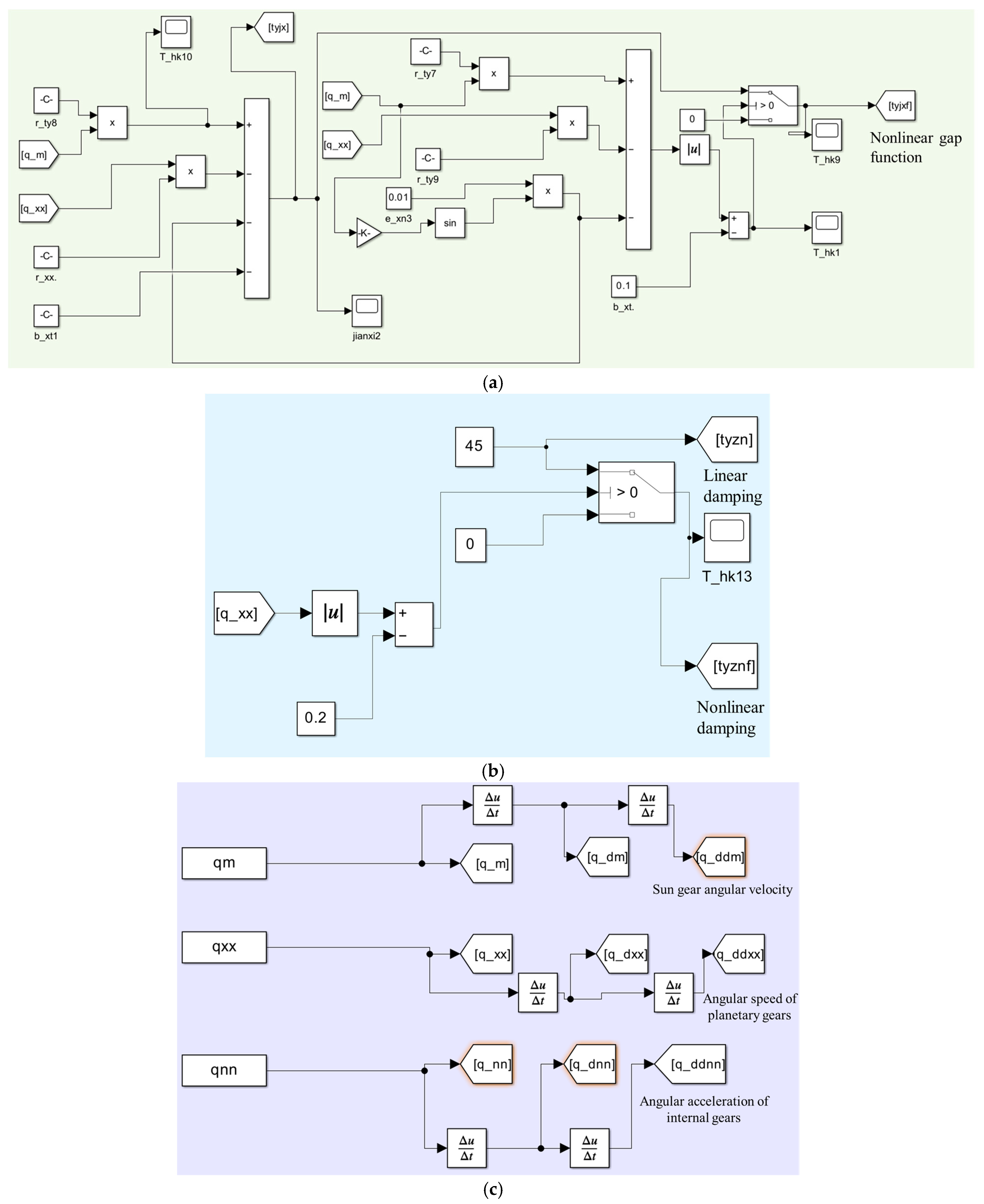
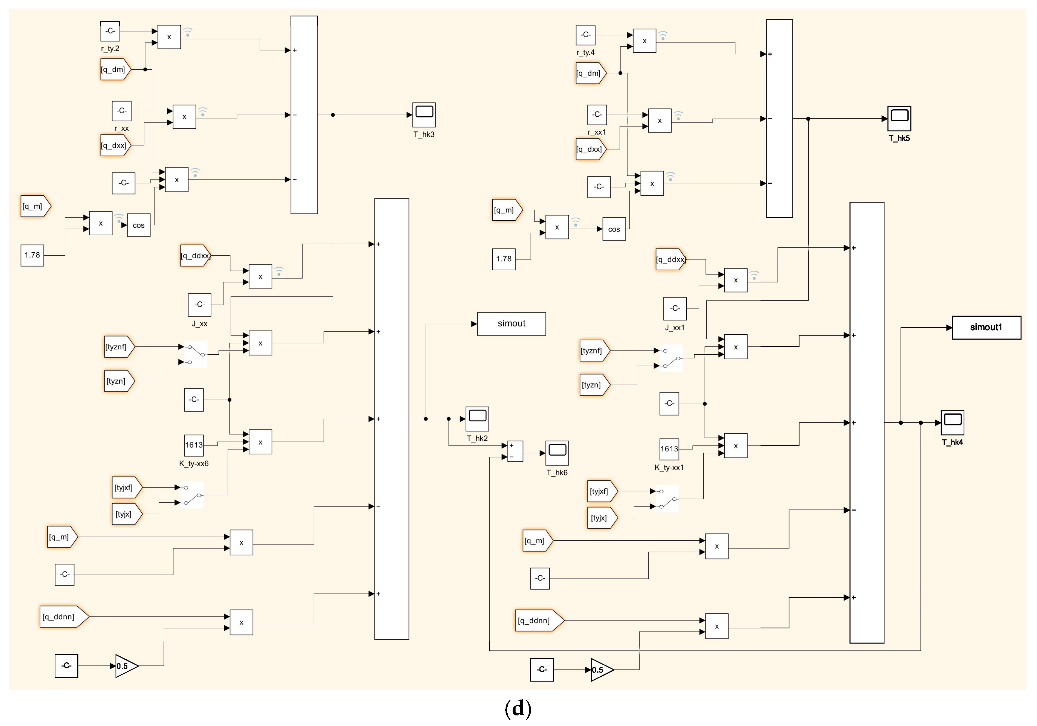
3.1. Discretisation and Expansion of Dynamical Models

To achieve parameter identification for the motion models of the internal gear and planetary gear, the nonlinear dynamic model is discretized and expanded. The goal is to convert the continuous-time system into a discrete-time system. This conversion enables numerical calculations and practical applications.
When r t y θ m r x x θ x x e x n ( t ) > b x n or r t y θ m r x x θ x x e x n ( t ) < - b x n and δ b , e x n ( t ) is infinitely small and can be ignored, Equation (7) can be changed to
T S = J n n θ ¨ n n + 2 K x x n n r n n 2 θ n n 2 K x x n n r n n r x x i θ x x i + 2 C x x n n r n n 2 θ ˙ n n 2 C x x n n r n n r x x i θ ˙ x x i i = 1 , 2
Depending on the degree of influence of the parameters on the drive, Equation (16) can be reduced to the following:
J x x i θ ¨ x x i = K t y x x r t y f ( r t y θ m r x x i θ x x i ) + C t y x x r t y ( r t y θ ˙ m r x x i θ ˙ x x i ) K x x n n r n n r n n θ n n r x x i θ x x i + C x x n n r n n r n n θ ˙ n n r x x i θ ˙ x x i - T h k i
3.
The discretisation of the equations for internal gears and planetary gears.
Equation (28) is collapsed into the following form:
θ ¨ n n = 2 K x x n n r n n 2 J n n θ n n 2 C x x n n r n n 2 J n n θ ˙ n n , + 2 K x x n n r n n r x x i J n n θ x x i + 2 C x x n n r n n r x x i J n n θ ˙ x x i + 1 J n n T s
In order to convert Equation (5) into the form of a state space expression, set the auxiliary parameter vector α .
α = [ α 1 α 2 α 3 α 4 α 5 ] T = 2 K x x n n r n n 2 J n n   2 C x x n n r n n 2 J n n   2 K x x n n r n n r x x i J n n   2 C x x n n r n n r x x i J n n   1 J n n T
According to Equation (30), the model parameters J n n , K x x n n , and C x x n n are as in Equation (7) in both characterization methods.
J n n = 1 α 5 C 1 x x n n = α 4 2 r t y 2 α 5 ; C 2 x x n n = α 2 2 r n n 2 α 5 K 1 x x n n = α 1 2 r t y r x x i α 5 ; K 2 x x n n = α 3 2 r n n r x x i α 5
Set the system state to the following:
x = [ x 1 x 2 x 3 x 4 x 5 ] T = [ θ n n θ ˙ n n θ x x i θ ˙ x x i T s ] T
The above equation is transformed into a continuous state space equation as follows:
x ˙ 1 = x 2 x ˙ 2 = α 1 x 1 α 2 x 2 + α 3 x 3 + α 4 x 4 + α 5 x 5 x ˙ 3 = x 4 x ˙ 4 = 0 x ˙ 5 = 0
In order to achieve the parameter identification of the internal gear and planetary gear motion model, according to Equations (30) and (32), the augmented state vector x is composed as follows:
x = [ x 1 x 2 x 3 x 4 x 5 x 6 x 7 ] T = [ θ n n θ ˙ n n α 1 α 2 α 3 α 4 α 5 ] T
The input vector of the system is set to u
u = [ u 1 u 2 u 3 ] T = [ θ x x i θ ˙ x x i T s ] T
The nonlinear motion model function f (⋅) can be transformed into
x ˙ 1 = x 2 x ˙ 2 = α 1 x 1 α 2 x 2 + α 3 u 1 + α 4 u 2 + α 5 u 3 x ˙ 3 7 = 0 5 × 1
Although the dynamical equations of the APVSA are expressed in terms of continuous differential equations, the corresponding equations need to be discretised as the nonlinear Gaussian filtering needs to be implemented in a digital computer. The method used is the forward Euler method [44] based on truncated Taylor series approximation, which is obtained by a truncated Taylor expansion of x t k + h at neighbourhood t k = k h :
x ( k + h ) = x ( k ) + h d x ( t ) d t k + ο ( h 2 )
where h is the step size and Euler’s approximation takes the first two terms, so that we have the following equation:
x ( k + 1 ) x ( k ) + h x ( t ) d t k
Therefore, Equation (36) is converted to the following:
x k + 1 = x ( k + 1 ) x ( k + 2 ) x ( k + 3 ) x ( k + 4 ) x ( k + 5 ) x ( k + 6 ) x ( k + 7 ) = x 1 ( k ) + h x ˙ 2 ( k ) x 2 ( k ) + h ( x 3 ( k ) x 1 ( k ) x 4 ( k ) x 2 ( k ) + x 5 ( k ) u 1 ( k ) + x 6 ( k ) u 2 ( k ) + x 7 ( k ) u 3 ( k ) ) x 3 ( k ) x 4 ( k ) x 5 ( k ) x 6 ( k ) x 7 ( k ) + w k
Combining the equations of motion in Equation (38) and the observation equations in Equation (34), Equation (27) is transformed into a state space expression. The continuous vector x t is transformed into the discrete vector x k .
  • The discretisation of the equations between the sun and planetary gears.
Equation (28) is obtained by simplifying the parameters according to their degree of influence on the drive:
K t y x x r t y f r t y θ m r x x i θ x x i + C t y x x r t y r t y θ ˙ m r x x i θ ˙ x x i K x x n n r n n r n n θ n n r x x i θ x x i + C x x n n r n n r n n θ ˙ n n r x x i θ ˙ x x i = J x x i θ ¨ x x i + T h k i
The meshing stiffness K x x n n and meshing damping C x x n n , which are obtained through the identification of the dynamic model of the internal gear and planetary gear, are substituted into Equation (40) and integrated.
Setting K x x n n r n n r n n θ n n r x x i θ x x i + C x x n n r n n r n n θ ˙ n n r x x i θ ˙ x x i T h k i = T in Equation (40), we obtain the following:
θ ¨ x x i = K t y x x r t y r x x i J x x i θ x x i C t y x x r t y r x x i J x x i θ ˙ x x i + K t y x x r t y 2 J x x i θ m + C t y x x r t y 2 J x x i θ ˙ m 1 J x x i T
In order to convert Equation (41) into the form of a state space expression, set the auxiliary parameter vector α .
α = [ α 1 α 2 α 3 α 4 α 5 ] T = K t y x x r t y r x x i J x x i   C t y x x r t y r x x i J x x i   K t y x x r t y 2 J x x i   C t y x x r t y 2 J x x i   1 J x x i T
According to Equation (42), the model parameters J x x i , K t y x x , and C t y x x are calculated as follows:
J x x i = 1 α 5 C 1 t y x x = α 2 2 r t y r x x i α 5 ; C 2 t y x x = α 4 2 r t y 2 α 5 K 1 t y x x = α 1 2 r t y r x x i α 5 ; K 2 t y x x = α 3 2 r t y 2 α 5
Set the system state to
x = [ x 1 x 2 x 3 x 4 x 5 ] T = [ θ x x i θ ˙ x x i θ m θ ˙ m T ] T i = 1 , 2
Equation (40) is transformed into a continuous state space equation as follows:
x ˙ 1 = x 2 x ˙ 2 = θ 1 x 1 θ 2 x 2 + θ 3 x 3 + θ 4 x 4 + θ 5 x 5 x ˙ 3 = x 4 x ˙ 4 = 0 x ˙ 5 = 0
In order to achieve the parameter identification of the motion model of the sun and planetary gears, the augmented and generalised state vectors are formed according to Equation (45), as follows:
x = [ x 1 x 2 x 3 x 4 x 5 x 6 x 7 ] T = [ θ x x i θ ˙ x x i θ 1 θ 2 θ 3 θ 4 θ 5 ] T
The input vector of the system is set to u:
u = [ u 1 u 2 u 3 ] T = [ θ m θ ˙ m T ] T
The nonlinear motion model function f (⋅) can be transformed into the following:
x ˙ 1 = x 2 x ˙ 2 = α 1 x 1 α 2 x 2 + α 3 u 1 + α 4 u 2 α 5 u 3 x ˙ 3 7 = 0 5 × 1
Using the method of Equations (37) and (38), Equation (48) can be converted into the following:
x k + 1 = x ( k + 1 ) x ( k + 2 ) x ( k + 3 ) x ( k + 4 ) x ( k + 5 ) x ( k + 6 ) x ( k + 7 ) = x 1 ( k ) + h x ˙ 2 ( k ) x 2 ( k ) + h ( x 3 ( k ) x 1 ( k ) x 4 ( k ) x 2 ( k ) + x 5 ( k ) u 1 ( k ) + x 6 ( k ) u 2 ( k ) x 7 ( k ) u 3 ( k ) ) x 3 ( k ) x 4 ( k ) x 5 ( k ) x 6 ( k ) x 7 ( k ) + w k
Combining the equations of motion in Equation (49) and the observation equations in Equation (41), Equation (40) is transformed into a state space expression. Continuous vectors transform to discrete vectors. Continuous vector x ( t ) transforms to the x k discrete vector.

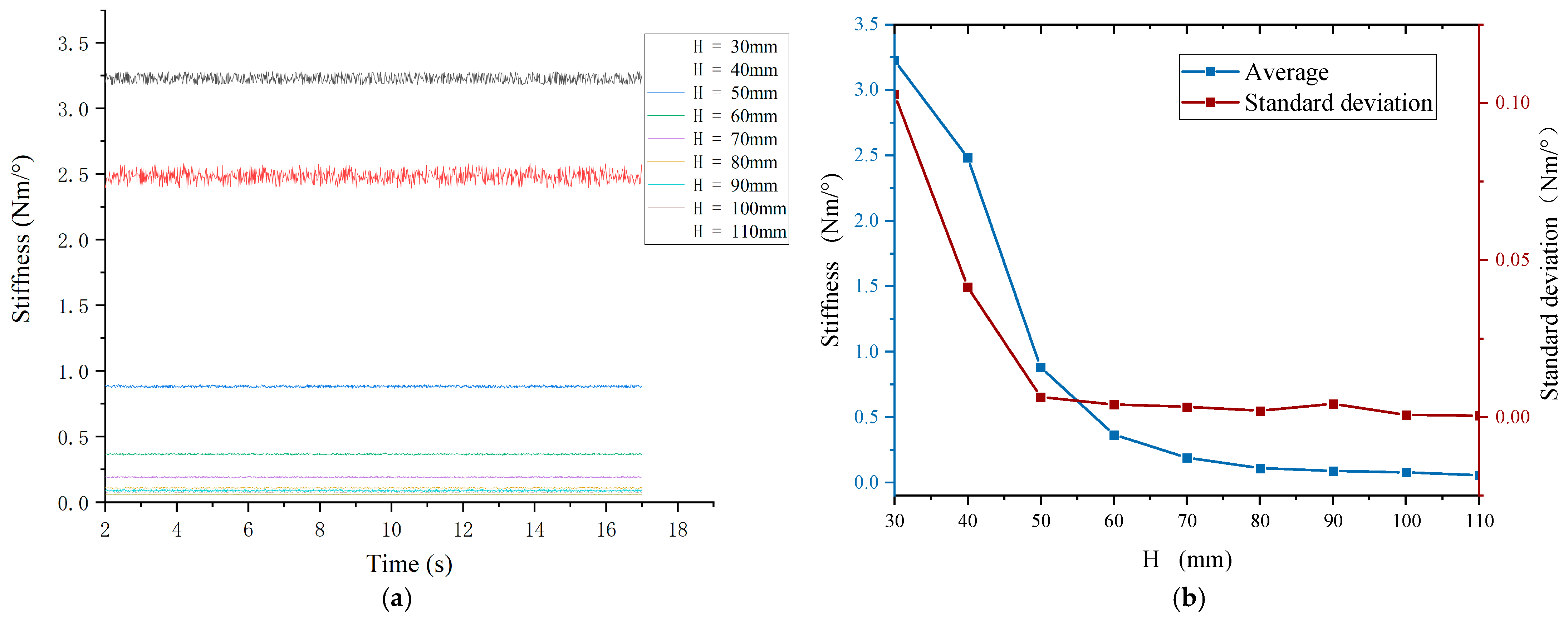
3.2. APVSA Stiffness Simulation Analysis

In order to analyse the impact of variable stiffness elastic actuator nonlinear dynamics, it is necessary to first use Adams simulation to obtain the rotation angle of the internal parts, according to the relationship between the internal angle of the elastic actuator through the Simulink study of the nonlinear dynamics model.
The dynamics simulation of the designed variable stiffness elastic actuator is carried out based on Adams 2020 software [45,46,47]. The variable stiffness elastic actuator is subjected to the stiffness adjustment motor and main motor, and the moment difference between the planetary gear and internal gear, input and output angle difference, and input moment and output moment inside the actuator are measured, and the variable stiffness performance of the actuator is calculated and analysed, and several sets of data are measured by varying the distance of the sliders, so that each parameter is finally obtained under different slider distances.
The relationship between the variable stiffness elastic actuator internal gear and planetary gear with different rotation angles is analysed as the distance H between the slider changes. When H takes different values, the rotation angles of both the internal gear and the planetary gear obtained after simulation are shown in Figure 6. When H increases from 30 mm to 110 mm, the rotation angle of the internal gear increases to a maximum of ±12.5° and the rotation angle of the planetary gear increases to a maximum of ±35°. The greater the distance between the sliders, the greater the rotation angle of the internal gear and the planetary gear. With the increase in time, both the internal gear and the planetary gear show periodic changes, which is in line with the design law.
The figure above shows that the rotation angles of the planetary gear and the internal meshing gear exhibit periodic changes as the sliders moves to different positions. Figure 7a shows the values of the input torque required by the actuator to maintain this periodic motion. According to the torque transmission principle illustrated in Figure 1, the input torque must pass through the elastic elements before being delivered to the load. As a result, there is a certain difference between the input and output torques. Figure 7b illustrates the output torque of the actuator.
According to Equation (19), two parameters are required to determine the stiffness of the APVSA. The first is the difference between the rotation angles of the internal gear and the planetary gear, as shown in Figure 8a. The second is the difference between the input torque and the output torque, as shown in Figure 8b. The angle difference of the APVSA increases as the slider distance H increases. When H = 30 mm, the difference between the internal gear angle and the planetary gear angle reaches its minimum value of 55°. When H = 100 mm, the angle difference reaches its maximum value of 120°. At H = 30 mm, the difference between the input torque and the output torque is maximum, and the torque difference is 250 N m; at H = 100 mm, the difference between the input torque and the output torque is minimum, and it is 3.47 N m.
By calculation, the stiffness of the variable stiffness elastic actuator shows a nonlinear variation with the distance H from the centre of the sliders to the centre line of the sun gear, and the stiffness of the actuator decreases with the increase in the distance H, as shown in Figure 9a. Figure 9b describes the average stiffness and standard deviation of stiffness on the basis of Figure 9a. In the range of 50 mm < H < 110 mm, the average stiffness change rate and standard deviation are relatively small. In the range of 30 mm < H < 50 mm, the average stiffness change rate and standard deviation vary more significantly. The average maximum stiffness is 3.27 N·m/°, and the average minimum stiffness is 0.065 N·m/°. The maximum standard deviation is 0.102 N·m/°, and the minimum standard deviation is 0.005 N·m/°. The reason for this inconsistency can be explained by Equation (26). When the denominator approaches zero, the rate of change (slope) of the function increases sharply. This causes the curve to become significantly steeper near the critical point. As H decreases, the rate of change in stiffness K increases significantly. This indicates a highly nonlinear relationship between the system stiffness and changes in H.
According to Figure 9, the stiffness of the driver reaches the minimum value when H = 110 mm. In order to verify the impact resistance of the variable stiffness driver under the limit conditions, the decision is made to apply the instantaneous impact load in this stiffness minimum state. According to Figure 10, when the impact torque is 26 Nm, the drive flexible angle reaches a maximum of −46.64°, accompanied by nine oscillations. The decay time is 2.8 s and the steady state value is 3.66°. This result shows that the driver can effectively absorb the impact energy and quickly recover the steady state, which fully reflects its excellent impact resistance and maximum impact resistance.

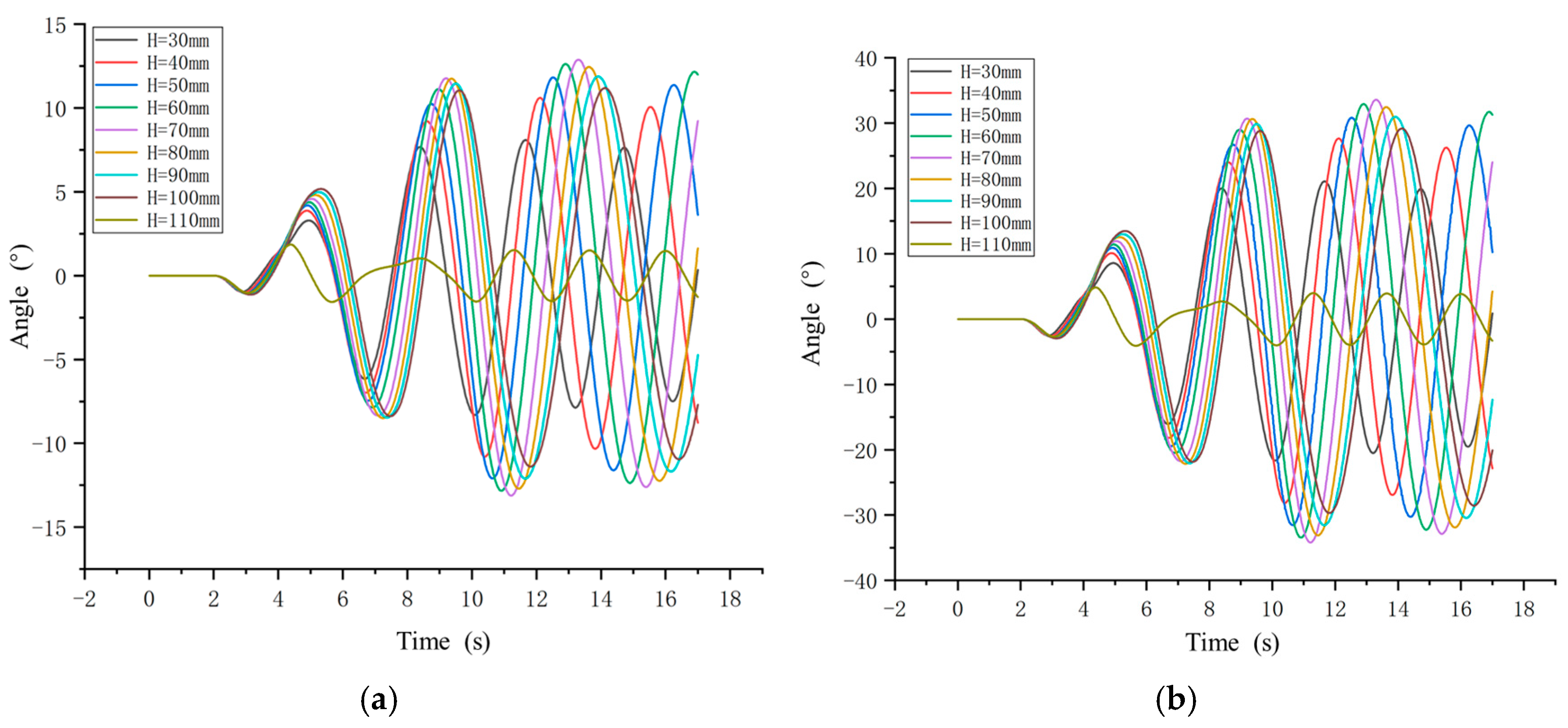
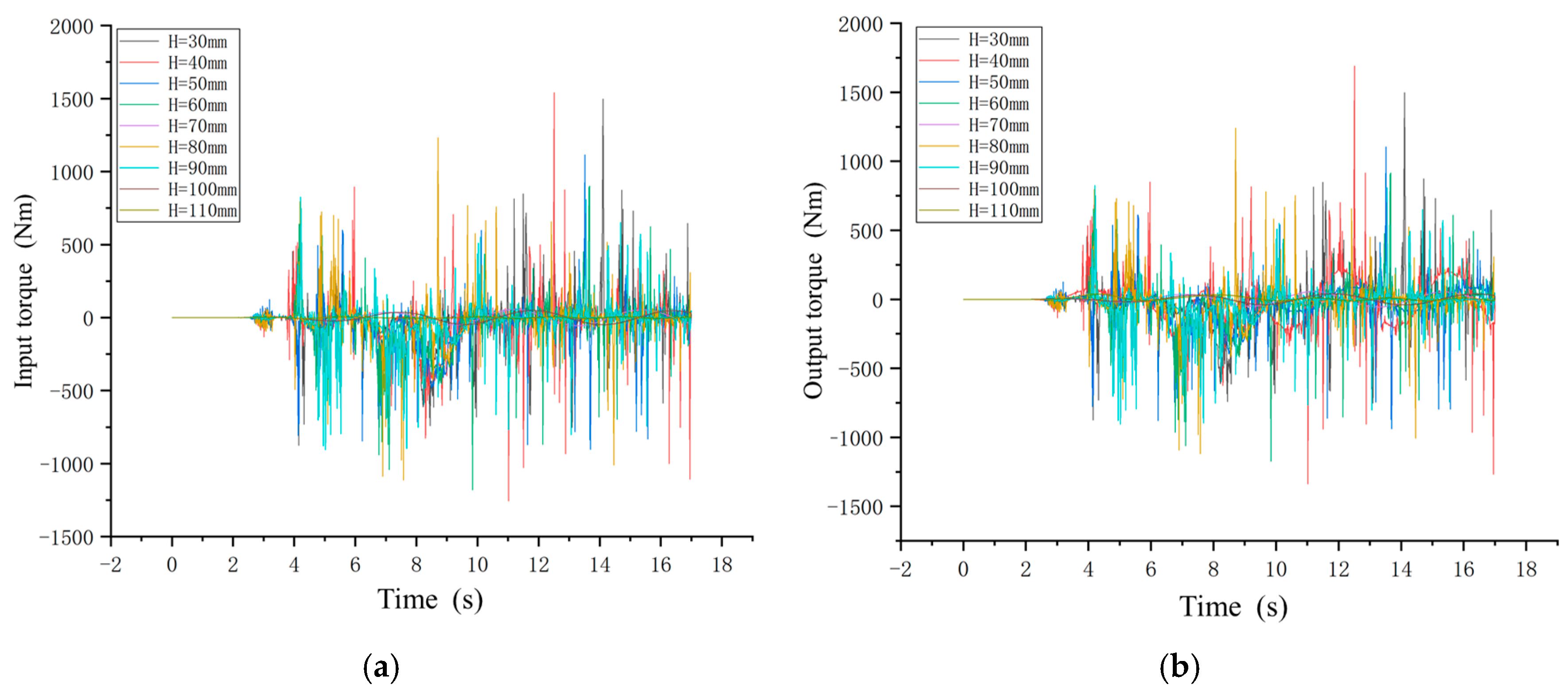
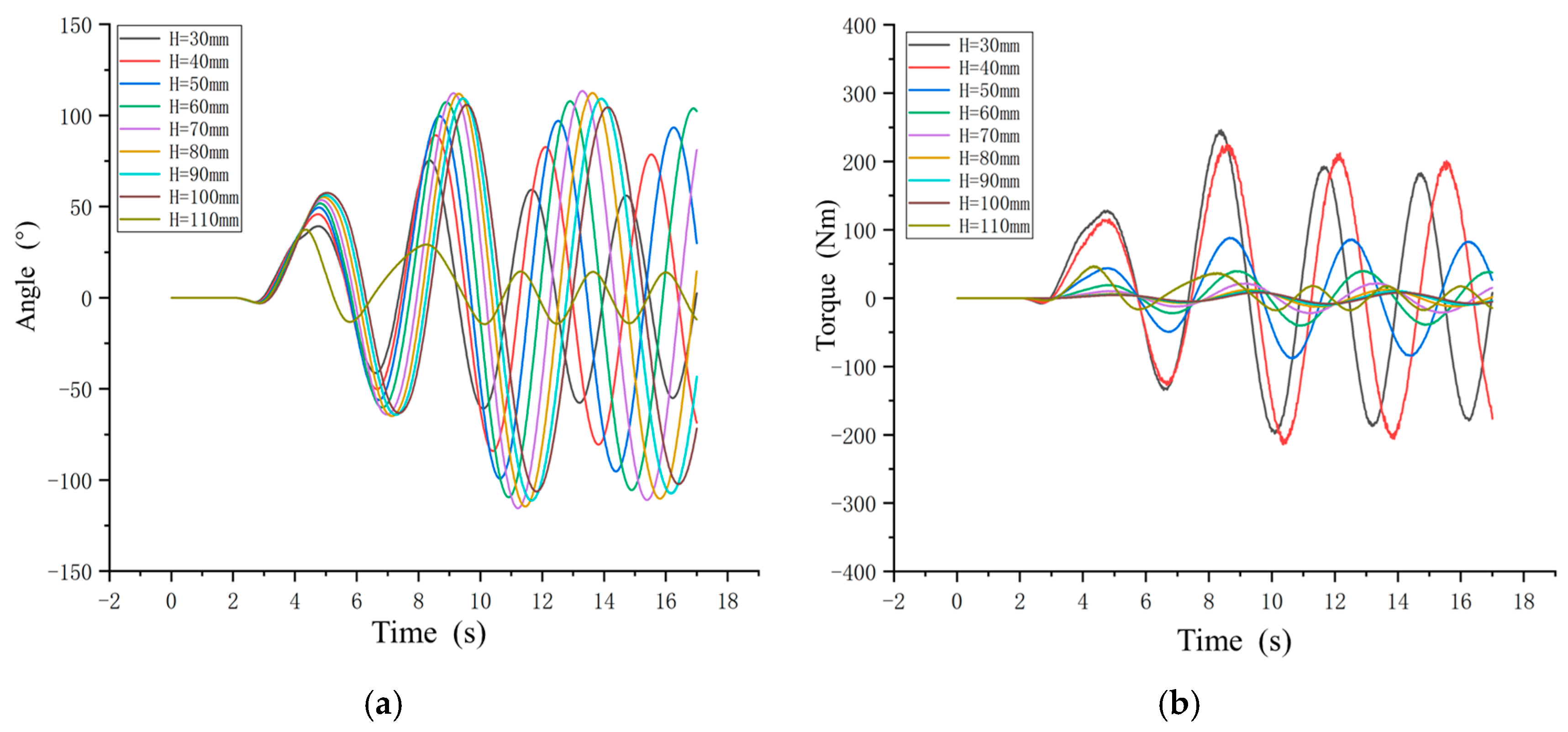
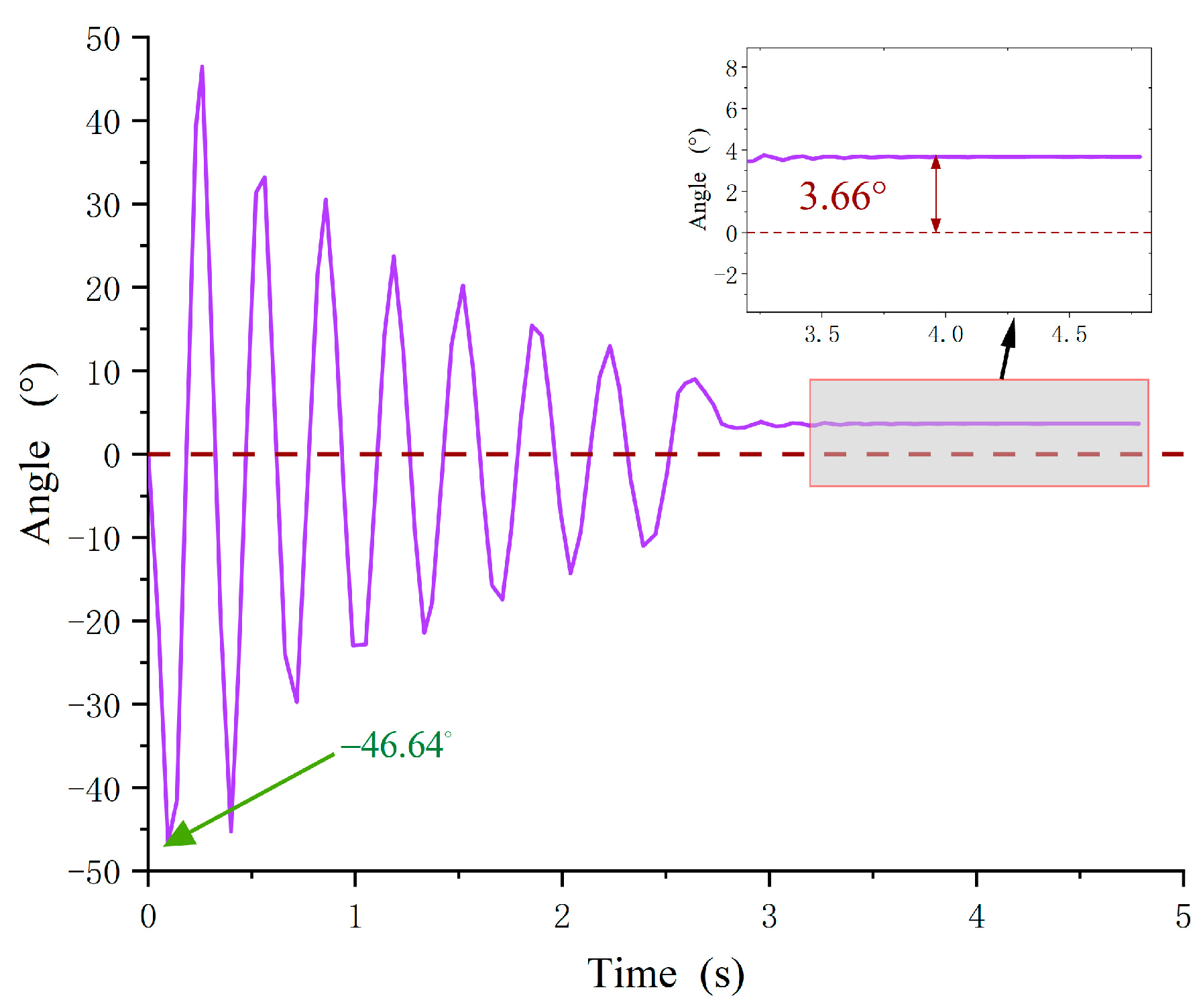
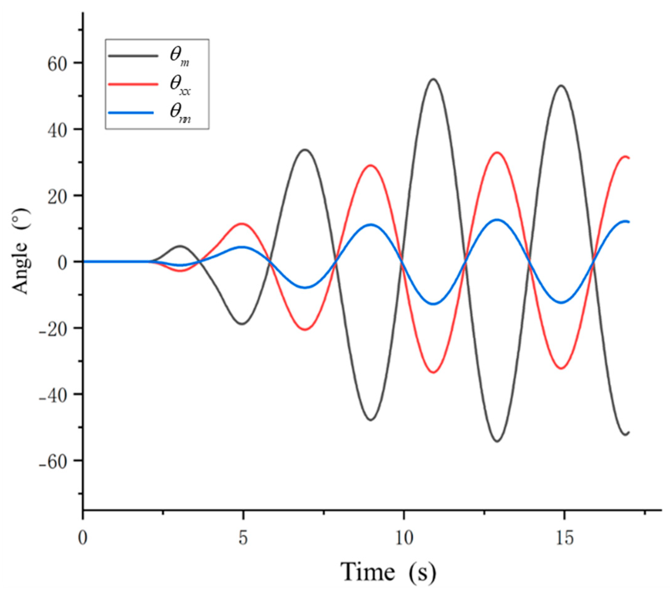
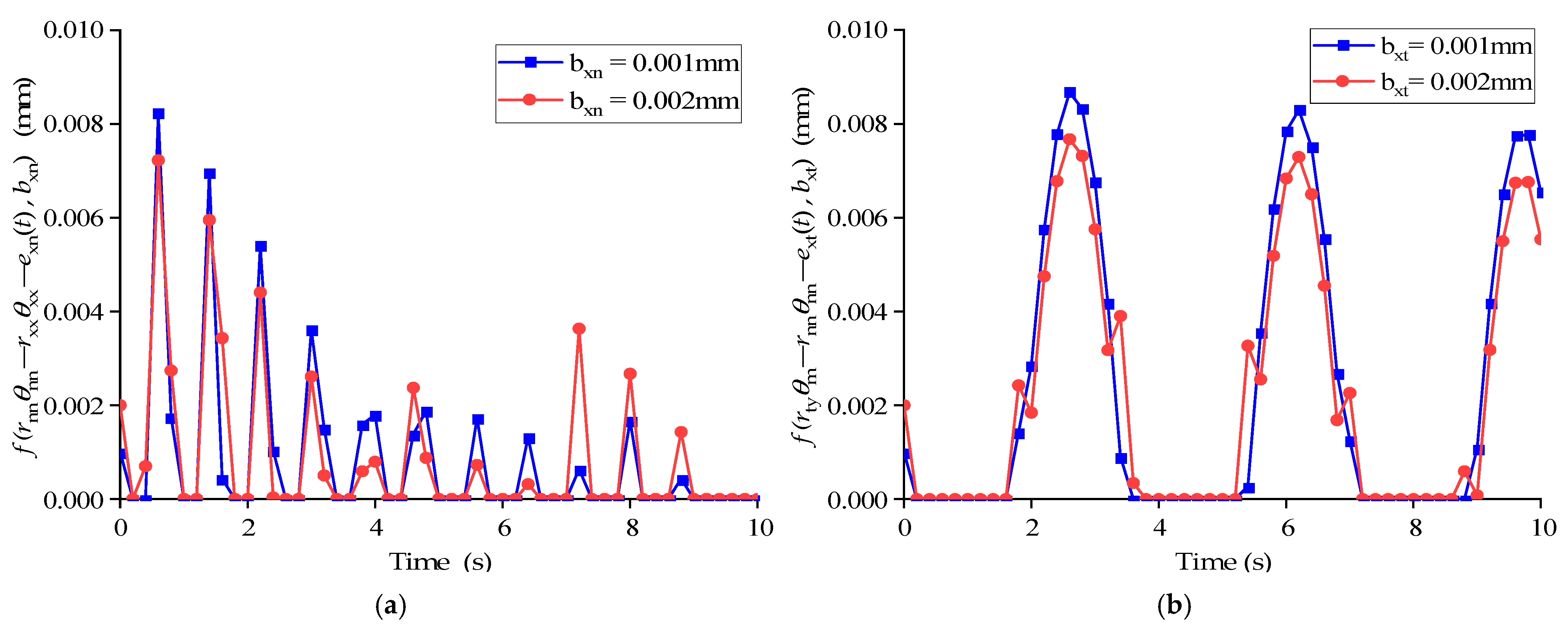
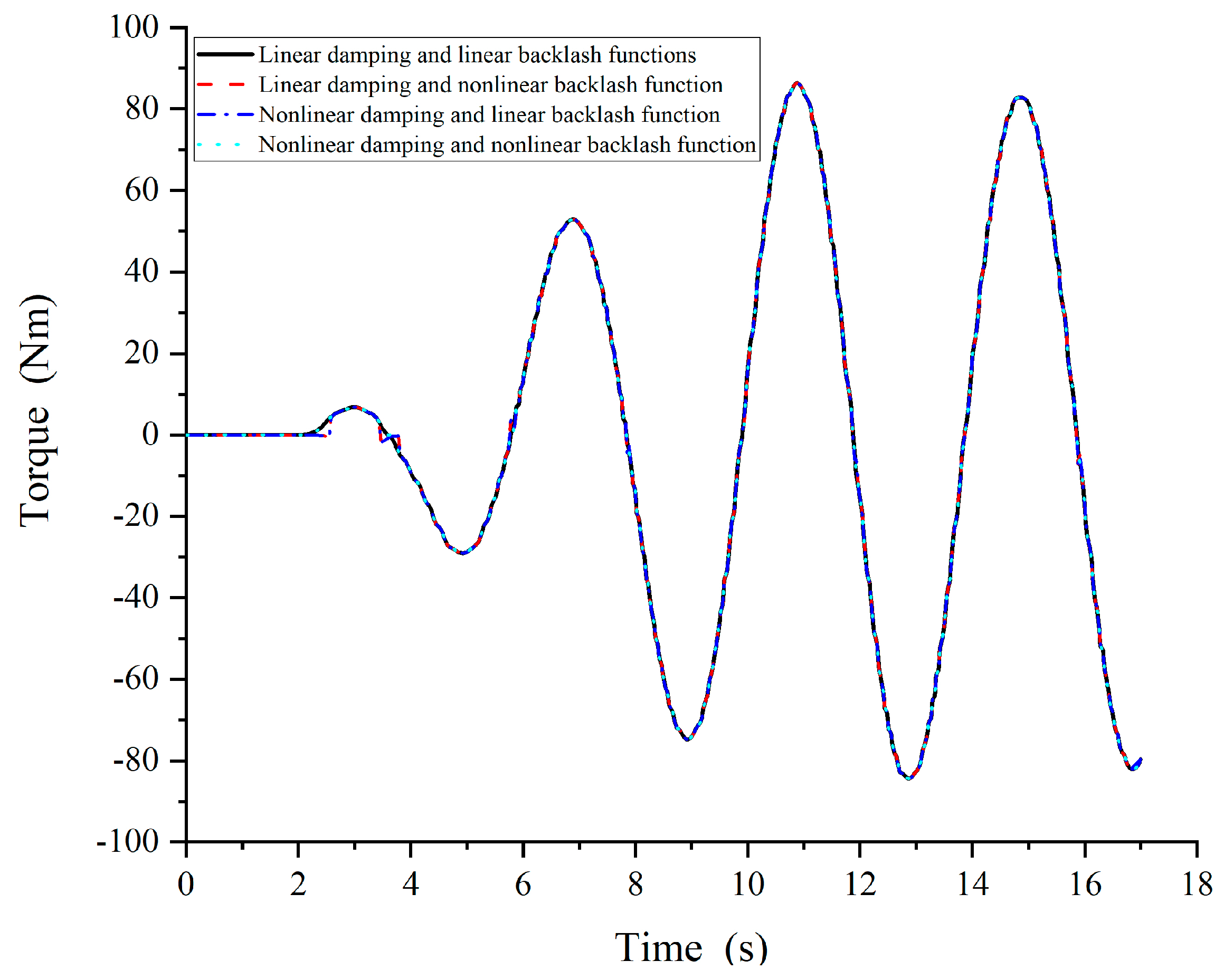
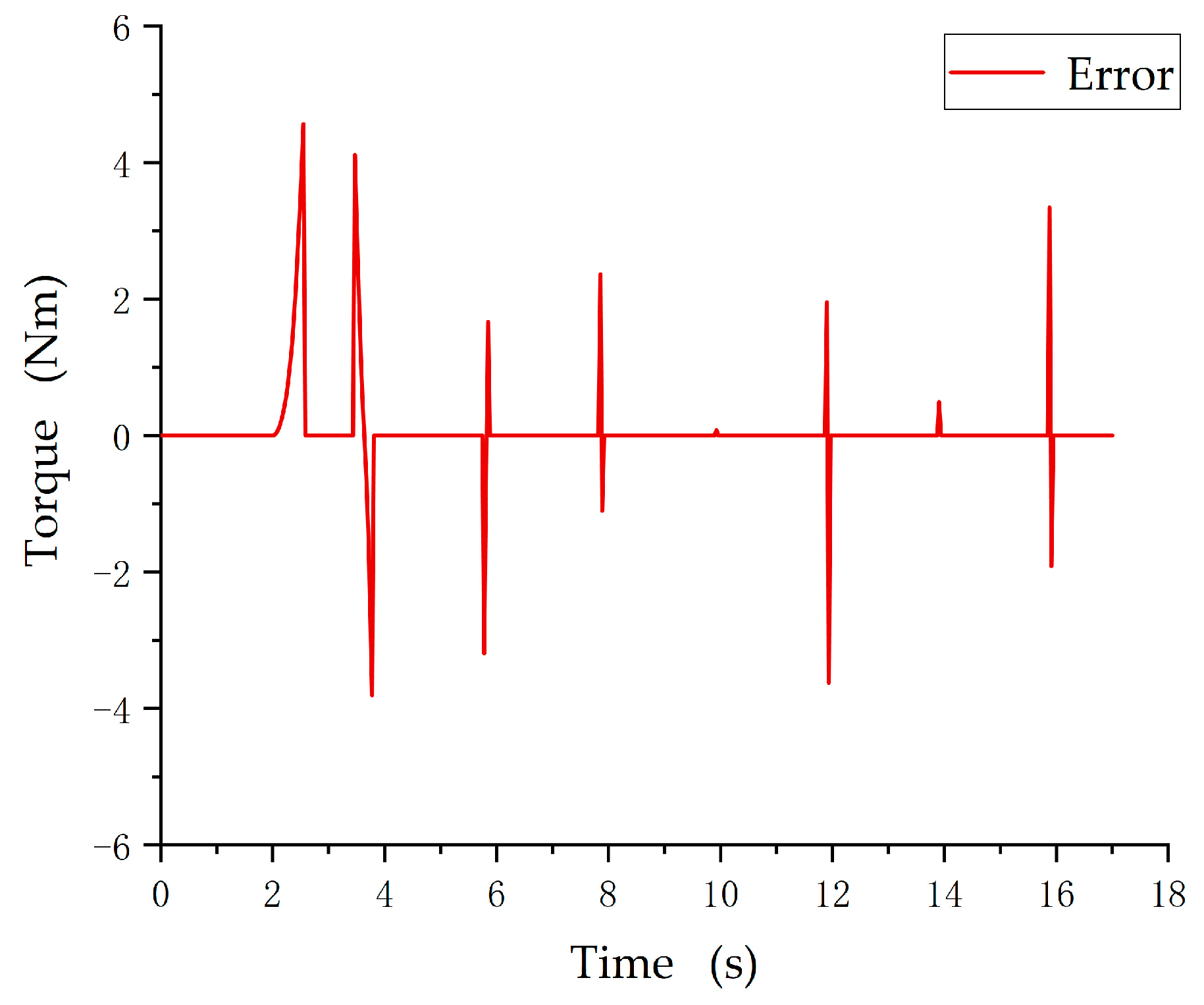
3.3. Simulation and Analysis of APVSA Nonlinear Dynamics Model

Based on the identification framework of nonlinear Gaussian filtering, the unknown parameters of the dynamic equations between the internal gear and the planetary gear, and the dynamic equations between the sun gear and the planetary gear are identified. For such nonlinear systems, the algorithm has high filtering accuracy and good filtering stability. We simulate the actual working state of the variable stiffness elastic actuator by using Adams, and obtain the working state parameters such as the rotation angle of the corresponding parts through the measurement function of Adams. The obtained working state parameters are used for the identification of the kinetic parameters, and the results are shown in Table 2.
The simulation is carried out using Simulink 2022 software [48,49,50] to analyse the effect of APVSA nonlinear damping and the nonlinear backlash function on the output torque. The simulation of each parameter is set as shown in Table 2. Set H = 80 mm, and import the θ n n , θ x x , and θ m data obtained from Adams as known parameters, as shown in Figure 11, into the Simulink simulation.
According to Equation (10), the nonlinear backlash function model is constructed, according to Equation (11), the nonlinear damping model is constructed, and according to Equation (17), the Simulink model of the variable stiffness elastic actuator is constructed as shown in Figure 12.
In order to illustrate the influence caused by the gear backlash, the varieties of gear backlash are obtained as shown in Figure 13a based on the above Equation (4) for the planetary gear and the internal gear with a gear backlash b x n of 0.001 mm and 0.002 mm. The nonlinear gear backlash is obtained as shown in Figure 13b based on the above Equation (10) for the planetary gear and the sun gear with a gear backlash b x t of 0.001 mm and 0.002 mm.
Figure 13a,b show that, when the slope of the gear backlash function value is zero, the tooth surface meshing lays in the separation state. Then, the impact force of the gear transmission is zero. When the slope of the tooth side backlash function is greater than zero, the tooth surface meshing lays in the normal state, and the impact force of the gear transmission is uniform. The figures indicate that the increase in gear backlash induces the gear transmission system to enter into irregular motion from cyclic motion. Meanwhile, they suggest the tooth surface meshing appears to produce a separation phenomenon, inducing an unequal impact force of gear transmission.
The drive torque is transmitted from the motor to the drive shaft. Then, this torque is transferred to the planetary gear via the internal meshing gear and the sun gear to the output torque. During the transmission, several gears are involved. The engagement of each gear pair shows the actual nonlinear backlash between them. Further, the nonlinear backlash exhibits a cumulative effect. Then, the output torque can be determined by the nonlinear backlash.
During the multi-stage gear transmission, nonlinear damping exacerbates the issue of torque fluctuations. Due to the characteristics of nonlinear damping, irregular fluctuations in output torque occur when the APVSA undergoes rapid changes. These fluctuations are transmitted and amplified stage by stage, affecting the final torque transmission.
According to the Simulink 2022 model above, the effects of backlash function nonlinearity and damping nonlinearity on the output torque of the actuator are obtained as shown in Figure 14, Figure 15, Figure 16 and Figure 17.
From Figure 14 and Figure 17, it can be seen that both nonlinear backlash and nonlinear damping affect the output torque. When both nonlinear backlash and nonlinear damping exist, the error of output torque exists at every moment, and the maximum error reaches 4.8 N m.
When the backlash function is linear, the output moment changes regularly as the input angle is sinusoidal. When the backlash function is nonlinear, as shown in Figure 15, the output moments change irregularly, and the nonlinear backlash function affects the output moments up to a maximum value of 4.8 N m. When the damping is linear, the output moments change regularly with the sinusoidal input angle. When the damping is nonlinear, as shown in Figure 14, the output moment also shows irregular changes, and the maximum value of the effect of nonlinear damping on the output moment is 3.2 N m.
The nonlinear gear backlash disadvantage is that the gear pair conversion steering will bring return error and shock, which will lead to variable stiffness drive error, and so in the study of dynamic equations and the subsequent construction of the controller, in order to simulate results the rigour of the gear backlash is a very important part of the gear drive.

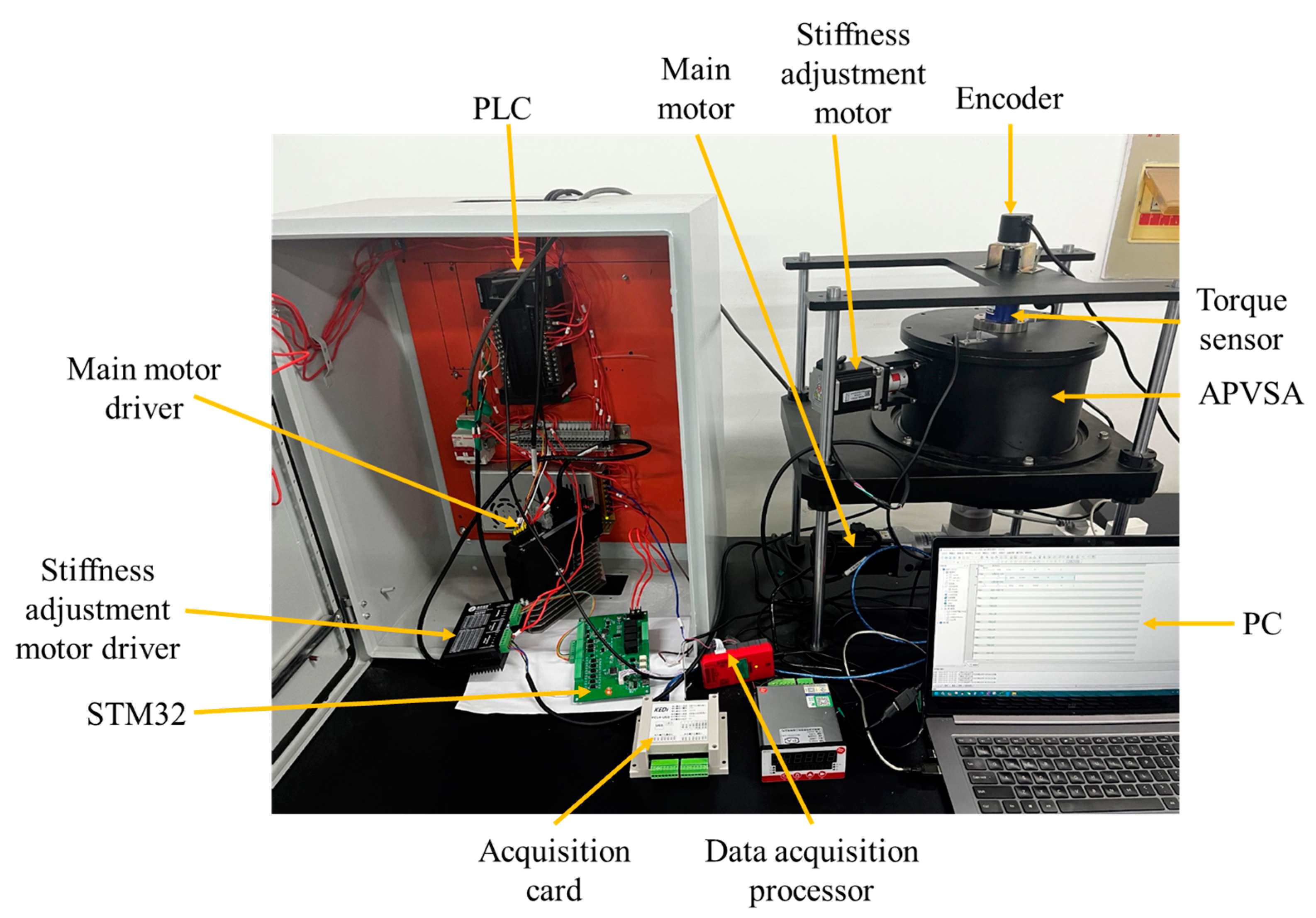
4. Experimental Verification

The experimental platform is shown in Figure 18. The torque transducer is connected to the flexible rotor shaft and connecting rod of the actuator through the flanges on both sides to achieve the measurement of the output torque of the flexible rotor shaft. An encoder is installed between the actuator housing and the flexible rotor shaft to read the passive flexible angle of the actuator.

4.1. Sliders Movement Experiment

The installation of the displacement measurement device is shown in Figure 19. The laser displacement sensor is fixed at the upper end of the flange cover. The L-shaped block is fixed on the sliders. The distance H1 between the laser displacement sensor and the L-shaped block is measured. Due to space constraints, there is a certain error between the measured position H1 of the laser displacement sensor and the distance H to the sliders. Specifically, this error is H1 = H + 19 mm.
In order to detect the relationship between the rotation angle of the stiffness adjustment motor and the distance between the sliders, the control board is connected to the stiffness adjustment motor on the driver, and the test is repeated to get the distance between the two sliders by using the laser displacement sensor. The results are shown in Figure 20.
As can be seen from Figure 16, the sliders can follow the rotation angle of the stiffness adjustment motor for regular movement. However, the actual moving distance is less than the theoretical distance due to the role of friction and the rotational inertia of the stiffness adjustment motor.
The sliders can follow the rotational angle of the stiffness adjustment motor to perform regular motion. However, due to the effects of friction and the rotational inertia of the stiffness adjustment motor, the actual movement distance is less than the theoretical distance. During the experiment, the maximum error between theory and practice was 2.5 mm. Compared to the total movement distance of 80 mm, the error ratio is 3.125%, which meets the expected results. The STM32 was used as the stiffness adjustment motor controller to drive the sliders movement.

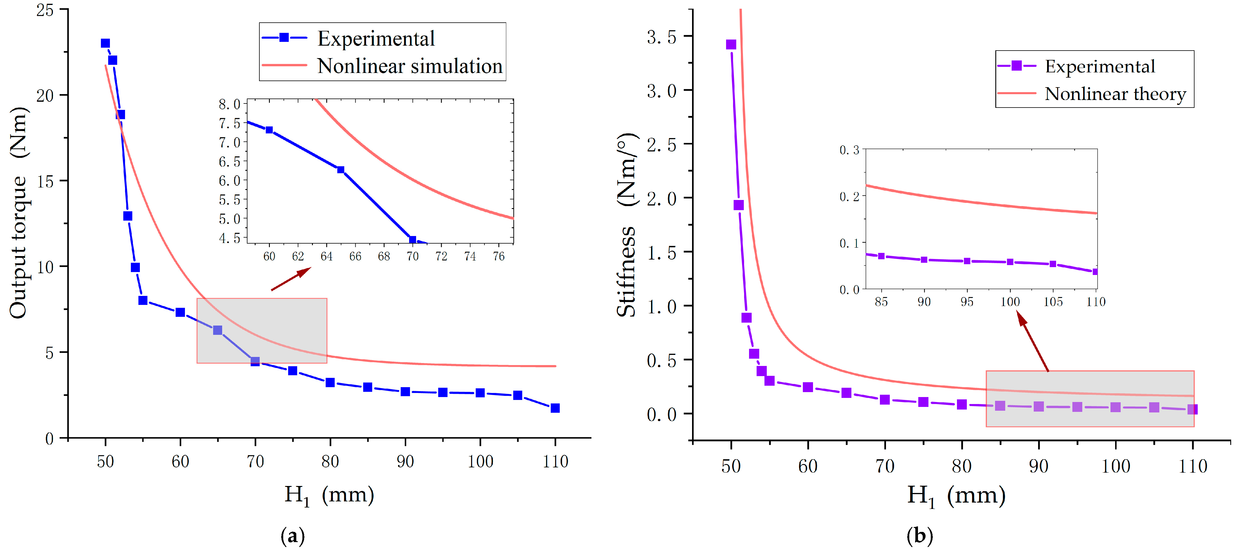
4.2. Static Stiffness Test

To express the relationship between joint stiffness and the slider distance H, it is necessary to obtain the flexible rotation angle and the magnitude of the torque. By continuously adjusting the distance between the sliders, the limit compression angle was measured at the output end by using an encoder.
The output torque was measured with the condition where the output end was fixed and the main motor was slowly applied until the spring reached full compression.
Figure 21a shows the relationship between the flexible angles from three experimental results, the theoretical flexible angles for different distances H1. The results indicate that the flexible angle increases as the distance between the sliders increases. The range of the flexible angle is 11.3° to 45.2° on average. Figure 21b displays the errors between the three experiments and the theoretical values. The maximum error is 8.35°, and the average error is 4.24°. The reason for this discrepancy is that there are slight variations in the distance between the sliders in each experiment, leading to some deviation between the theoretical and experimental results.
Under the condition of no load, the above experimental process is repeated to obtain the relationship between the output torque T and the distance H1. The results are shown in Figure 22a. From Figure 22b it can be seen that the stiffness change is more sensitive near H1 = 53 mm. In the range of 53 mm ≤ H1 ≤ 60 mm, the stiffness change with the distance H1 is obvious and smooth; however, the stiffness change is not obvious in the range of 60 mm < H1 ≤ 110 mm. Comparing the experimental data with the theoretical data, the maximum error of the stiffness occurs at H1 = 55 mm with an error value of 0.67 Nm/°; the maximum error of torque occurs at H1 = 55 mm with an error value of 14 Nm. The reason for the errors may be that there is a certain error between the actual distance and the theoretical distance of the slider when the driver is converted from high stiffness to low stiffness.

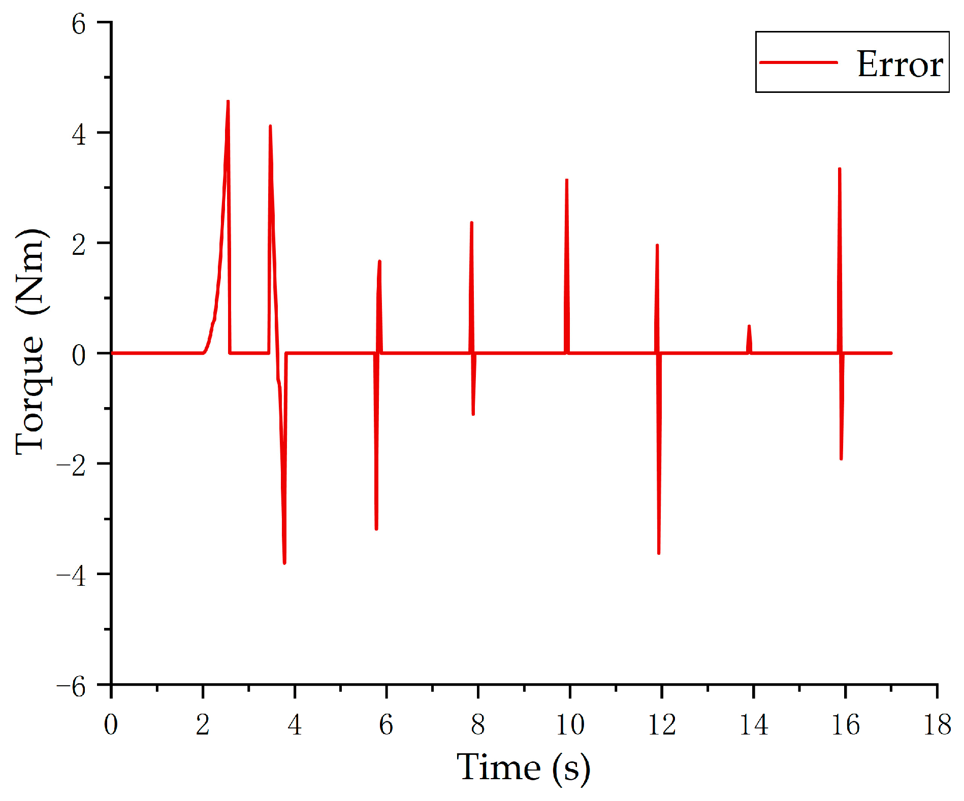
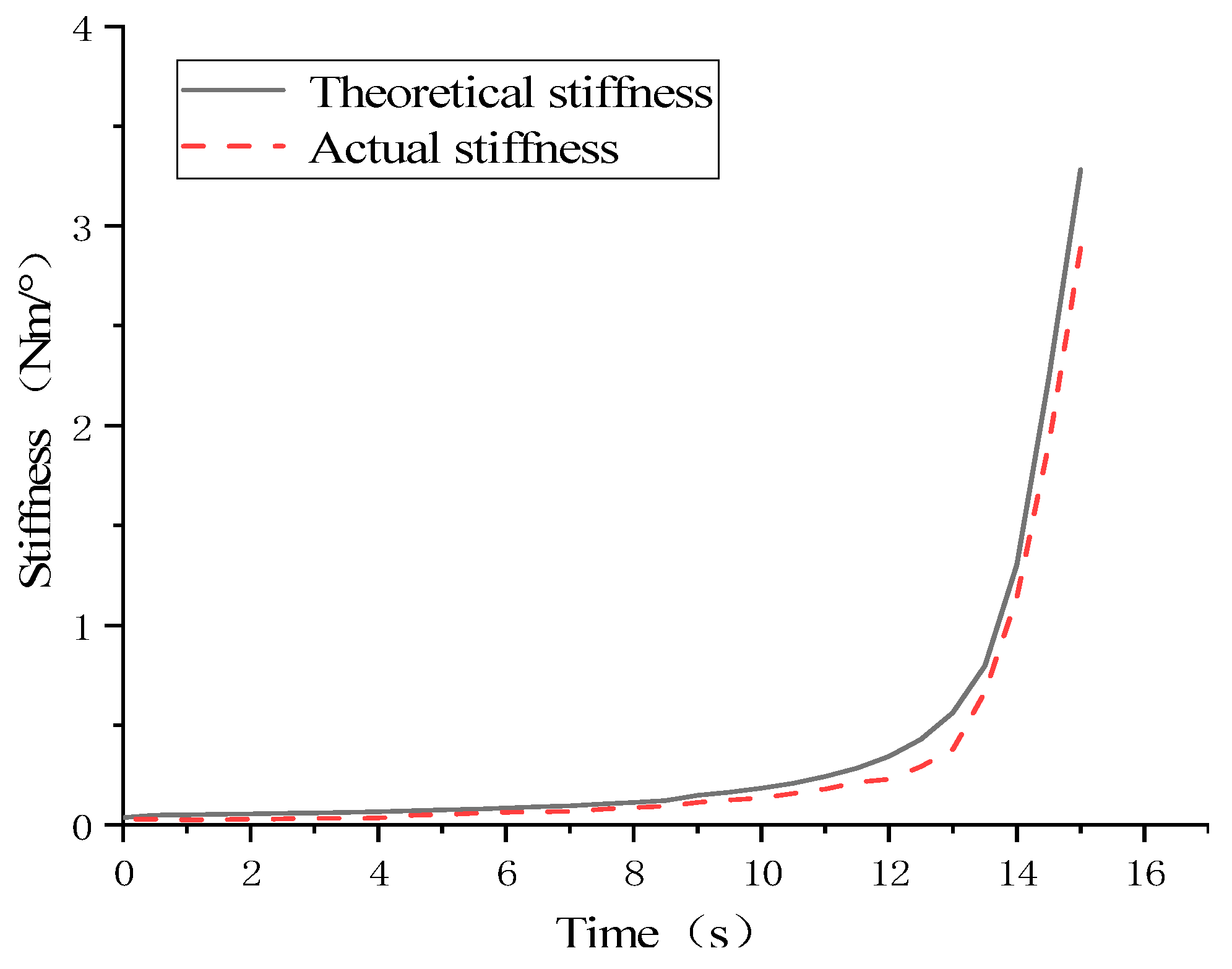
4.3. Dynamic Stiffness Experiment

As shown in Figure 23, in the experiment, a load of m = 2000 g is applied at the end of the APVSA, and when the end state of the actuator is stable, the stiffness adjustment motor is controlled to change the actuator stiffness. At this time, the control strategy is as follows: first record the flexible angle of the actuator under this load. If the change in the stiffness state of the actuator leads to a change in the flexible angle, the distance between the sliders is controlled to keep the flexible angle between the output axis inside the actuator and the stiffened gear ring constant. At the same time, the stiffness adjustment motor controls the pivot point to move along a straight line at a constant speed. According to the stiffness model analysis, the output stiffness of the actuator will increase approximately linearly with time. With the gradual increase in stiffness, the absolute flexible angle of the output axis of the actuator relative to the horizontal position will gradually decrease. With the above adjustments, it is able to fulfil the experimental objectives without relying on the moment sensor. It can be concluded that the change in the flexible angle at a certain two instantaneous moments is due to the change in stiffness, so that the load mass is m, the effective output moment is L, the angle at the time of t 1 is θ 1 , and the angle at the time of t 2 is θ 2 ; then, the instantaneous output stiffness of the actuator can be calculated according to Equation (50).
K a = cos θ 1 cos θ 2 θ 1 θ 2 m g L
The initial angle under this load is 0.17 rad, the maximum distance between the sliders is 110 mm, and the minimum distance is 50 mm; 14 s becomes the minimum distance for the sliders. Set the sliders with the time function as follows:
H = 110 4.29 t
Substituting into the stiffness curve Equation (9), the relationship between stiffness and sliders distance can be obtained as follows:
K = 2 T h k H cos θ x x φ x x j cos θ m θ s H 2 + r t y + r x x 2 2 H r t y + r x x cos φ x x j
where the angle of the initial position is zero, and except for the sliders, all of the institutions are stationary, so θ x x = θ m = θ s = φ x x j = 0 , and the relationship between stiffness and time is as follows:
K = 2 T h k 110 4.29 t 110 4.29 t 2 + r t y + r x x 2 2 110 4.29 t r t y + r x x
The output rotation angle has an encoder to measure and the data is collected every 0.05 s. The results are shown in Figure 24.
It can be concluded from Figure 24 that with the change in time when the distance between the sliders becomes small, the change in stiffness first increases slowly, and shows an exponential increase at 12 s. In the low stiffness, the theoretical stiffness and the actual stiffness are not much different; in the high stiffness, the theoretical stiffness and the actual stiffness have an error, in which the distance between the sliders is 50 mm when the error is the largest, and the maximum error is 0.685 N m/rad. The reasons for the error are as follows: On the one hand, it is possible that due to the load of the driver, the distance between the two sliders cannot reach the theoretical distance of 50 mm, resulting in the stiffness of the error. On the other hand, the measured output angle is smaller than the theoretical output angle due to the excessive friction of the internal mechanism, which leads to the error in the actual stiffness.

5. Discussion

In this paper, an active and passive composite variable stiffness elastic actuator (APVSA) was designed. A nonlinear dynamic model was established to account for the nonlinear factors in the APVSA, followed by discretization processing. In addition, dynamic simulation analysis and maximum impact resistance analysis of APVSA were performed based on Adams software. The analysis results show that the APVSA reaches a maximum flexible angle of 46.64° for the actuator when subjected to a maximum impact of 26 Nm. This demonstrates the effectiveness of the APVSA in enhancing the safety of human–robot interaction.
The nonlinear dynamics model was established by considering nonlinear factors such as nonlinear gear lash, nonlinear damping, and integrated transmission error. The nonlinear dynamics model was verified by using both Adams and Simulink to analyse the effects of nonlinear gears backlash and nonlinear damping on the output torque of APVSA. Backlash-free gears or low-damping bearings can be used to reduce the effect of nonlinear factors on the actuator output torque.
The experimental platform of APVSA was constructed. The experiments of slider distance, structural stiffness, and dynamic stiffness were carried out, respectively. Experimental results indicate the theoretical stiffness of APVSA closely matches actual stiffness at low stiffness levels. However, small errors occur at high stiffness levels. These differences stem from factors like gear backlash and friction. Despite this variance, the overall performance meets the expected stiffness adjustment targets. It provides important support for its application in fields such as robotics and human–robot collaboration.
The parameters of APVSA were identified and they can be used to develop controllers for intelligently adjusting the stiffness according to task requirements.

6. Patents

The authors hold a patent related to this work.

Author Contributions

Conceptualization, C.W.; investigation, Z.Z.; methodology, C.W.; formal analysis, P.G.; software, Y.X.; project administration, C.W. and X.L.; writing—original draft, Z.Z. and P.G.; writing—review and editing, C.W. and Z.Z. All authors have read and agreed to the published version of the manuscript.

Funding

This research was supported by the Science and Technology Research Project of Henan Province (Grant No. 252102221059), National Natural Science Foundation of China (Grant No. 52375034 and No. 52075500) and the Program for Science & Technology Innovation Talents in Universities of He-nan Province (Grant No. 22HASTIT023).

Data Availability Statement

The original contributions presented in this study are included in the article. Further inquiries can be directed to the corresponding author(s).

Conflicts of Interest

The authors declare no conflicts of interest.

Appendix A

This appendix lists the definitions of all letter symbols, variables, and parameters used in this document.
Table A1. Nomenclature.
ParameterSymbol
(Unit)
ParameterSymbol
(Unit)
ParameterSymbol
(Unit)
Torque between sun gear and planetary gear 1 T t y x x 1
(Nm)
Angle of the rigid motor θ h
(°)
Moment of inertia of internal gears J n n
(kg·m2)
Torque between sun gear and planetary gear 2 T t y x x 2
(Nm)
Output housing rotation angle θ w k
(°)
Output housing moment of inertia J w k (kg·m2)
Planetary gear 1 output torque T h k 1
(Nm)
Gear indexing circle radius r m
(mm)
Moment of inertia of the sun gear J t y
(kg·m2)
Planetary gear 2 output torque T h k 2
(Nm)
Radius of the base circle of internal gears r n n (mm)Slider 1 is pushed by the stopper F h k 1
(N)
Input torque T i
(Nm)
Radius of the base circle of the sun gear r t y (mm)Slider 2 is pushed by the stopper F h k 2
(N)
Torque generated by the internal gear on the planetary gear 2 T n n x x 2
(Nm)
Radius of the base circle of the planetary gear 1 r x x 1 (mm)The component force in the horizontal direction of the slider F z o n g
(N)
Torque generated by the internal gear on the planetary gear 1 T n n x x 1
(Nm)
Radius of the base circle of the planetary gear 2 r x x 2 (mm)Horizontal force provided by the stiffness adjustment motor F b j
(N)
Internal gear torque T s
(Nm)
Damping coefficients of gear ratios for internal gears and planetary gears C x x n n (s/m)Combined transmission error of internal gears and planetary gears e x n t (mm)
Meshing stiffness of internal gears and planetary gears K x x n n (Nm/°)Damping of the output housing C w k (s/m)Combined transmission error of sun gear and planetary gear e x t t (mm)
Meshing stiffness of sun gears and planetary gears K t y x x (Nm/°)Damping coefficients of the gear train for sun gears and planetary gears C t y x x (s/m)Distance from the center of the input shaft to the rack l s
(mm)
Torque coefficient of the motor K t
(Nm/°)
Frequency of meshing of internal gears with planetary gears μ x n
(°/s)
Distance between slider and housingL
(mm)
Stiffness of the output housing K w k
(Nm/°)
Gear meshing frequency μ x t (°/s)ElectricityI
(A)
Actuator stiffnessK
(Nm/°)
Mass of the slider m h k (kg)Number of internal gear teeth z n n
Equivalent stiffness of a springkSpring viscous damping coefficient B k Number of sun gear teeth z t y
Input shaft angle θ m
(°)
Flexible angleρ
(°)
Backlash error between internal gears and planetary gears b x n
(mm)
Angle of planetary gear i. i = 1,2 θ x x i
(°)
Moment of inertia of planetary gear 1 J x x 1
(kg·m2)
Backlash error between sun gear and planetary gears b x t
(mm)
Angle of planetary gear 2 θ n n
(°)
Moment of inertia of planetary gear 2 J x x 2
(kg·m2)
Planetary gear 1 speed ω 1
(°/s)
Acceleration of the slider a h k
(m/s2)
Laser encoder measuring distance H 1
(mm)
Planetary gear 2 speed ω 2
(°/s)
Screw guidel
(mm)
Motor speedN
(°/s)
Angle of rotation of planetary gear carrier φ x x j
(°/s)

References

  1. Kahnamouei, J.T.; Moallem, M. Advancements in Control Systems and Integration of Artificial Intelligence in Welding Robots: A Review. Ocean Eng. 2024, 312, 119294. [Google Scholar] [CrossRef]
  2. Chen, T.Y.; Dong, S.J.; Deng, C.M.; Zhang, X.F.; Jiang, J.N.; Deng, L.H.; Cai, Z.H.; Cao, X.Q. Proposition of a Robot-Based Free Diamond Abrasive Grinding Process and Its Influence on the Characteristics of Plasma-Sprayed 8ysz Coatings. J. Mater. Res. Technol.-JMRT 2023, 26, 4423–4435. [Google Scholar] [CrossRef]
  3. Choi, W.; Suh, J. Design and Evaluation of a Cable-Actuated Palletizing Robot with Geared Rolling Joints. IEEE-ASME Trans. Mechatron. 2024, 29, 3137–3145. [Google Scholar] [CrossRef]
  4. Li, Z.; Chu, X.Y.; Hu, X.Y.; Zhang, Z.Y.; Li, N.P.; Li, J.F. Variable Stiffness Methods for Robots: A Review. Smart Mater. Struct. 2024, 33, 063002. [Google Scholar] [CrossRef]
  5. Clark, A.B.; Rojas, N. Malleable Robots: Reconfigurable Robotic Arms with Continuum Links of Variable Stiffness. IEEE Trans. Robot. 2022, 38, 3832–3849. [Google Scholar] [CrossRef]
  6. Wolf, S.; Grioli, G.; Eiberger, O.; Friedl, W.; Grebenstein, M.; Höppner, H.; Burdet, E.; Caldwell, D.G.; Carloni, R.; Catalano, M.G.; et al. Variable Stiffness Actuators: Review on Design and Components. IEEE-ASME Trans. Mechatron. 2016, 21, 2418–2430. [Google Scholar] [CrossRef]
  7. Vanderborght, B.; Albu-Schaeffer, A.; Bicchi, A.; Burdet, E.; Caldwell, D.G.; Carloni, R.; Catalano, M.; Eiberger, O.; Friedl, W.; Ganesh, G.; et al. Variable Impedance Actuators: A Review. Robot. Auton. Syst. 2013, 61, 1601–1614. [Google Scholar] [CrossRef]
  8. Sun, Y.X.; Tang, Y.T.; Zheng, J.; Dong, D.B.; Bai, L. Optimal Variable Stiffness Control and Its Applications in Bionic Robotic Joints: A Review. J. Bionic Eng. 2023, 20, 417–435. [Google Scholar] [CrossRef]
  9. Ham, R.V.; Sugar, T.G.; Vanderborght, B.; Hollander, K.W.; Lefeber, D. Compliant Actuator Designs. IEEE Robot. Autom. Mag. 2009, 16, 81–94. [Google Scholar] [CrossRef]
  10. Tung, T.T.; Van Tinh, N.; Phuong Thao, D.T.; Minh, T.V. Development of a Prototype 6 Degree of Freedom Robot Arm. Results Eng. 2023, 18, 101049. [Google Scholar] [CrossRef]
  11. Rodríguez-Guerra, D.; Sorrosal, G.; Cabanes, I.; Calleja, C. Human-Robot Interaction Review: Challenges and Solutions for Modern Industrial Environments. IEEE Access 2021, 9, 108557–108578. [Google Scholar] [CrossRef]
  12. Pu, H.Y.; He, L.; Cheng, P.; Sun, M.Y.; Chen, J.M. Security of Industrial Robots: Vulnerabilities, Attacks, and Mitigations. IEEE Netw. 2023, 37, 111–117. [Google Scholar] [CrossRef]
  13. Li, Y.B.; Guan, X.Y.; Li, Z.B.; Tang, Z.H.; Penzlin, B.; Yang, Z.; Leonhardt, S.; Ji, L.H. Analysis, Design, and Preliminary Evaluation of a Parallel Elastic Actuator for Power-Efficient Walking Assistance. IEEE Access 2020, 8, 88060–88075. [Google Scholar] [CrossRef]
  14. Oh, S.; Kong, K. High-Precision Robust Force Control of a Series Elastic Actuator. IEEE/ASME Trans. Mechatron. 2017, 22, 71–80. [Google Scholar] [CrossRef]
  15. Carpino, G.; Accoto, D.; Sergi, F.; Tagliamonte, N.L.; Guglielmelli, E. A Novel Compact Torsional Spring for Series Elastic Actuators for Assistive Wearable Robots. J. Mech. Des. 2012, 134, 10. [Google Scholar] [CrossRef]
  16. Liu, L.; Leonhardt, S.; Bergmann, L.; Misgeld, B.J.E. Composite Performance of Variable Stiffness Actuator for Exoskeleton Administrated Via Impedance Control and Disturbance Observer. Mech. Mach. Theory 2023, 179, 105096. [Google Scholar] [CrossRef]
  17. Xiong, J.; Sun, Y.; Zheng, J.; Dong, D.; Bai, L. Design and Experiment of a Sma-Based Continuous-Stiffness-Adjustment Torsional Elastic Component for Variable Stiffness Actuators. Smart Mater. Struct. 2021, 30, 105021. [Google Scholar]
  18. Albu-Schäffer, A.; Wolf, S.; Eiberger, O.; Haddadin, S.; Petit, F.; Chalon, M. Dynamic Modelling and Control of Variable Stiffness Actuators. In Proceedings of the 2010 IEEE International Conference on Robotics and Automation, Anchorage, Alaska, 3–7 May 2010; pp. 2155–2162. [Google Scholar]
  19. Eiberger, O.; Haddadin, S.; Weis, M.; Albu-Schäffer, A.; Hirzinger, G. On Joint Design with Intrinsic Variable Compliance: Derivation of the Dlr Qa-Joint. In Proceedings of the 2010 IEEE International Conference on Robotics and Automation, Anchorage, Alaska, 3–7 May 2010; pp. 1687–1694. [Google Scholar]
  20. Petit, F.; Friedl, W.; Höppner, H.; Grebenstein, M. Analysis and Synthesis of the Bidirectional Antagonistic Variable Stiffness Mechanism. IEEE/ASME Trans. Mechatron. 2015, 20, 684–695. [Google Scholar] [CrossRef]
  21. Liu, Y.; Liu, X.; Yuan, Z.; Liu, J. Design and Analysis of Spring Parallel Variable Stiffness Actuator Based on Antagonistic Principle. Mech. Mach. Theory 2019, 140, 44–58. [Google Scholar] [CrossRef]
  22. Li, Z.; Xu, P.; Li, B. A Novel Variable Stiffness Actuator Based on Cable-Pulley-Driven Mechanisms for Robotics. IEEE/ASME Trans. Mechatron. 2024, 29, 4699–4710. [Google Scholar] [CrossRef]
  23. Ji, C.; Kong, M.; Li, R. Time-Energy Optimal Trajectory Planning for Variable Stiffness Actuated Robot. IEEE Access 2019, 7, 14366–14377. [Google Scholar] [CrossRef]
  24. Sarani, B.; Ahmadi, H. Mechanical Design and Control of a Novel Variable Impedance Actuator (Via) for Knee Joint of a Rehabilitation Ex-oskeleton. J. Braz. Soc. Mech. Sci. Eng. 2022, 44, 81. [Google Scholar] [CrossRef]
  25. Dežman, M.; Gams, A. Rotatable Cam-Based Variable-Ratio Lever Compliant Actuator for Wearable Devices. Mech. Mach. Theory 2018, 130, 508–522. [Google Scholar] [CrossRef]
  26. Li, Z.; Xu, P.; Huang, H.; Ning, Y.; Li, B. A Novel Variable Stiffness Actuator Based on a Rocker-Linked Epicyclic Gear Train. Mech. Mach. Theory 2022, 177, 105035. [Google Scholar] [CrossRef]
  27. Xu, Y.; Guo, K.; Sun, J.; Li, J. Design, Modeling and Control of a Reconfigurable Variable Stiffness Actuator. Mech. Syst. Signal Process. 2021, 160, 107883. [Google Scholar] [CrossRef]
  28. Zhu, R.; Fei, Q.; Jiang, D.; Marchesiello, S.; Anastasio, D. Identification of Nonlinear Stiffness and Damping Parameters Using a Hybrid Approach. AIAA J. 2021, 59, 4686–4695. [Google Scholar] [CrossRef]
  29. Hu, B.; Liu, J.; Liu, S.; Li, B.; Lei, X. Simultaneous Multi-Parameter Identification Algorithm for Backlash-Type Nonlinearity. Mech. Syst. Signal Process. 2020, 139, 106423. [Google Scholar] [CrossRef]
  30. Ting, J.-A.; Mistry, M.N.; Peters, J.; Schaal, S.; Nakanishi, J. A Bayesian Approach to Nonlinear Parameter Identification for Rigid Body Dynamics. In Proceedings of the Robotics: Science and Systems, Philadelphia, PA, USA, 16–19 August 2006. [Google Scholar]
  31. Zhou, G.; Feng, T.; Lv, X.; Liu, L. Parameter Identification of Electro-Hydrostatic Actuator Based on Particle Swarm Optimization. J. Phys. Conf. Ser. 2020, 1486, 032031. [Google Scholar] [CrossRef]
  32. Wang, C.; Gao, P.; Wang, X.; Wang, H.; Liu, X.; Zheng, H. Mechanical Design and Experiments of a New Rotational Variable Stiffness Actuator for Hybrid Passive–Active Stiffness Regulation. Actuators 2023, 12, 450. [Google Scholar] [CrossRef]
  33. Yu, X.B.; Zhang, S.; Sun, L.; Wang, Y.; Xue, C.Q.; Li, B. Cooperative Control of Dual-Arm Robots in Different Human-Robot Collaborative Tasks. Assem. Autom. 2020, 40, 95–104. [Google Scholar] [CrossRef]
  34. Cherelle, P.; Grosu, V.; Beyl, P.; Mathys, A.; Ham, R.V.; Damme, M.V.; Vanderborght, B.; Lefeber, D. The Maccepa Actuation System as Torque Actuator in the Gait Rehabilitation Robot Altacro. In Proceedings of the 2010 3rd IEEE RAS & EMBS International Conference on Biomedical Robotics and Biomechatronics, Tokyo, Japan, 26–29 September 2010; pp. 27–32. [Google Scholar]
  35. Liu, L.; Leonhardt, S.; Misgeld, B.J.E. Design and Control of a Mechanical Rotary Variable Impedance Actuator. Mechatronics 2016, 39, 226–236. [Google Scholar] [CrossRef]
  36. Wang, W.; Fu, X.; Li, Y.; Yun, C. "Design and Implementation of a Variable Stiffness Actuator Based on Flexible Gear Rack Mechanism. Robot. Int. J. Inf. Educ. Res. Robot. Artif. Intell. 2018, 36, 448–462. [Google Scholar] [CrossRef]
  37. Lee, S.H.; Lee, H.J.; Lee, K.H.; Nam, K.T.; Koo, J.C. A Novel Variable Stiffness Scotch Yoke Series Elastic Actuator for Enhanced Functional Stiffness. Microsyst. Technol. 2020, 26, 3395–3402. [Google Scholar] [CrossRef]
  38. Karim, A.; Lindner, P.; Verl, A. Control-Based Compensation of Friction and Backlash within Rack-and-Pinion Drives. Prod. Eng. 2018, 12, 589–596. [Google Scholar] [CrossRef]
  39. Sun, J.; Guo, Z.; Sun, D.; He, S.; Xiao, X. Design, Modeling and Control of a Novel Compact, Energy-Efficient, and Rotational Serial Variable Stiffness Actua-tor (Svsa-Ii). Mech. Mach. Theory 2018, 130, 123–136. [Google Scholar] [CrossRef]
  40. Chen, G.; Chen, G.; Li, Y.; Zhao, N. Dynamic Analysis of a Face-Gear Drive with Spur Involute Pinion with Backlash Considered. Mech. Sci. Technol. Aerosp. Eng. 2009, 28, 5. [Google Scholar]
  41. Yu, X.; Sun, Y.; Li, H.; Wu, S. An Improved Meshing Stiffness Calculation Algorithm for Gear Pair Involving Fractal Contact Stiffness Based on Dynamic Contact Force. Eur. J. Mech.-A/Solids 2022, 94, 104595. [Google Scholar] [CrossRef]
  42. Sánchez, M.B.; Pleguezuelos, M.; Pedrero, J.I. Approximate Equations for the Meshing Stiffness and the Load Sharing Ratio of Spur Gears Including Hertzian Effects. Mech. Mach. Theory 2017, 109, 231–249. [Google Scholar] [CrossRef]
  43. Liu, S.; Liu, F. Vibration Characteristics of Spur Gear System with Non-Linear Damping under No Lubrication Condition. J. Vibroeng. 2019, 21, 1260–1270. [Google Scholar] [CrossRef]
  44. Wang, S.; Wang, L.; Im, N.; Zhang, W.; Li, X. Real-Time Parameter Identification of Ship Maneuvering Response Model Based on Nonlinear Gaussian Filter. Ocean Eng. 2022, 247, 110471. [Google Scholar] [CrossRef]
  45. Hu, J.; Liu, T.Y.; Zeng, H.J.; Chua, M.X.; Katupitiya, J.; Wu, L. Static Modeling of a Class of Stiffness-Adjustable Snake-like Robots with Gravity Compensation. Robotics 2023, 12, 2. [Google Scholar] [CrossRef]
  46. Sheng, L.C.; Xu, M.C.; Shen, J.W.; Li, W.; Ye, G. Design and Analysis of a Novel Flexible Variable Stiffness Damping Mechanism for Grinding Electric Spindle. J. Vib. Control 2024, 30, 4408–4420. [Google Scholar] [CrossRef]
  47. Shi, X.J.; Xu, J.; Chen, T.K.; Cong, Q.; Tian, W.J. Novel Low Frequency Bionic Vibration Isolation Structure. J. Vib. Control 2023, 29, 3357–3368. [Google Scholar] [CrossRef]
  48. Wei, F.; Zhang, L.X.; Zhang, Y.M.; Li, S.P.; Yao, K.; Li, C.J. Design and Analysis of a Novel Variable Stiffness Joints with Robots. Adv. Mech. Eng. 2024, 16, 16878132231219612. [Google Scholar] [CrossRef]
  49. Zhao, C.L.; Liu, Z.; Zheng, C.S.; Zhu, L.C.; Wang, Y.F. Research on Mechanical Leg Structure Design and Control System of Lower Limb Exoskeleton Rehabilitation Robot Based on Magnetorheological Variable Stiffness and Damping Actuator. Actuators 2024, 13, 132. [Google Scholar] [CrossRef]
  50. Wang, Y.W.; Wu, J.L.; Zhang, N.; Mo, W.W. Dynamics Modeling and Shift Control of a Novel Spring-Based Synchronizer for Electric Vehicles. Mech. Mach. Theory 2022, 168, 104586. [Google Scholar] [CrossRef]
Figure 1. Working principle of the APVSA.
Actuators 14 00169 g001
Figure 2. APVSA structure [32]: 1. input shaft; 2. rack-and-pinion system; 3. guide rod; 4. spring; 5. inner shell; 6. stiffness adjustment motor; 7. output shaft; 8. sliders; 9. ball screw; 10. sun gears; 11. grooved cam; 12. planetary gear; 13. internal gear; 14. planetary gear frame; 15. shell; 16. flange bearing with the shell as inner ring; 17. flange bearing; 18. gear; and 19. guide plate.
Actuators 14 00169 g002
Figure 3. Torque transmission mechanism.
Actuators 14 00169 g003
Figure 4. Passive stiffening mechanism diagram.
Actuators 14 00169 g004
Figure 5. Active stiffening mechanism.
Actuators 14 00169 g005
Figure 6. Rotation angle of internal gear and planetary gear: (a) rotation angle of rotation of internal gear and (b) rotation angle of planetary gear.
Actuators 14 00169 g006
Figure 7. Input and output torques at different distances of H. (a) Input torque. (b) Output torque.
Actuators 14 00169 g007
Figure 8. Difference of rotation angle between internal gear and planetary gear, and difference between input and output torques. (a) Angular difference. (b) Torque difference.
Actuators 14 00169 g008
Figure 9. Stiffness for different slider distances. (a) Stiffness. (b) Average stiffness and standard deviation.
Actuators 14 00169 g009
Figure 10. Maximum output angle under impact resistance.
Actuators 14 00169 g010
Figure 11. Angles of the internal gear, sun gear, and planetary gear under constant stiffness.
Actuators 14 00169 g011
Figure 12. Simulation model. (a) Nonlinear backlash. (b) Nonlinear damping. (c) Input function. (d) Output torque.
Actuators 14 00169 g012aActuators 14 00169 g012b
Figure 13. Nonlinear gear backlash. (a) Gear backlash of planetary gears and internal gear. (b) Gear backlash of planetary gears and sun gear.
Actuators 14 00169 g013
Figure 14. Output torque.
Actuators 14 00169 g014
Figure 15. Effect of nonlinear backlash on output torque.
Actuators 14 00169 g015
Figure 16. Effect of nonlinear damping on output torque.
Actuators 14 00169 g016
Figure 17. Effects of nonlinear backlash and nonlinear damping on output torque.
Actuators 14 00169 g017
Figure 18. Experimental platform.
Actuators 14 00169 g018
Figure 19. Measuring device of H.
Actuators 14 00169 g019
Figure 20. Slider movement experiment. (a) Comparison of actual distance and theoretical distance. (b) Error between actual distance and theoretical distance.
Actuators 14 00169 g020
Figure 21. Flexible angle. (a) Experiment and theory. (b) Error of flexible angles.
Actuators 14 00169 g021
Figure 22. Effect of different inter-slider distances on torsional stiffness. (a) Relationship between output torque and slider distance. (b) Variation in stiffness.
Actuators 14 00169 g022
Figure 23. Principle of experiment for dynamic stiffness.
Actuators 14 00169 g023
Figure 24. Theoretical and actual stiffness.
Actuators 14 00169 g024
Table 1. Performance comparisons of different actuators.
NameTypeStiffness (Nm/rad)Flexible Angle (°)
Baxter [33]Traditional robotinf.0
Robot Arm [10]Traditional robotinf.0
SEA [15]Passive actuators98±4.5
PEA [13]Passive actuators0.00529±24.9
BAVS [20]VSA (antagonistic)3.9–146.6±18.2
SPVSA [21]VSA (antagonistic)0–inf.±18.5
MACCEPA [34]VSA (variable spring-preload)5–11060
SDS-VSA [23]VSA (variable spring-preload)0–4680-
REGT-VSA [26]VSA (variable lever)20–2362±10.31
VSAPLM [24]VSA (variable lever)98–533.6±53
RVSA [27]VSA (variable spring physical parameter)20–inf.±8
MERIA [35]VSA (variable spring physical parameter)376–7158
Table 2. Parameter settings of the APVSA.
Parameter Value Parameter Value
J t y 8.858 × 10⁻⁴ kg·m2 z x x 28
J n n 1.669 × 10⁻³ kg·m2 k 4 N/mm
J x x 9.724 × 10⁻⁴ kg·m2 l s 0.045 m
K t y x x 1.613 × 10³ kg/m e x n ( t ) 0.01 sin 2 π z n n 60 mm
K n n x x 1.774 × 10³ N/m e x t ( t ) 0.01 sin 2 π z t y 60 mm
r t y 0.0255 m b x n 0.001 mm
r x x 0.0388 m b x t 0.001 mm
r n n 0.1095 m f 2 C t y x x f 2 × 45 kg·s/m
z t y 17 f 1 C n n x x f 1 × 35 kg·s/m
z n n 73Nonlinear backlash function of sun gear and planetary gear f r t y θ t y d r t y a θ t y 0.01 sin 2 π z t y 60 θ m , b x t
Disclaimer/Publisher’s Note: The statements, opinions and data contained in all publications are solely those of the individual author(s) and contributor(s) and not of MDPI and/or the editor(s). MDPI and/or the editor(s) disclaim responsibility for any injury to people or property resulting from any ideas, methods, instructions or products referred to in the content.

