Article

Modeling and Analysis of Transmission Efficiency for 3K Planetary Gearbox with Flexure-Based Carrier for Backdrivable Robot Joints

by
Qinghao Du
1,2,
Guilin Yang
1,2,*,
Weijun Wang
1,
Chin-Yin Chen
1,2 and
Zaojun Fang
1,2
1
Ningbo Institute of Materials Technology and Engineering, Chinese Academy of Sciences, Ningbo 315201, China
2
University of Chinese Academy of Sciences, Beijing 100049, China
*
Author to whom correspondence should be addressed.
Actuators 2025, 14(4), 173; https://doi.org/10.3390/act14040173
Submission received: 24 February 2025 / Revised: 19 March 2025 / Accepted: 31 March 2025 / Published: 1 April 2025

Abstract

:
A high-gear-ratio anti-backlash 3K planetary gearbox with a preloaded flexure-based carrier is a suitable reducer for robot joints owning to its compact design and high transmission accuracy. However, to design such a 3K planetary gearbox with high bidirectional efficiencies for backdrivable robot joints, it is critical to develop an accurate transmission efficiency model to predict the effects of the preloaded flexure-based carrier on the efficiency of the 3K planetary gearbox. To determine the meshing forces of gear pairs in the 3K planetary gearbox, a quasi-static model is formulated according to tangential displacements of planet gears resulting from the preloaded flexure-based carrier. Considering the reverse meshing forces in the anti-backlash 3K planetary gearbox, a modified efficiency model is developed and the bidirectional transmission efficiencies are analyzed. Simulation results show that both forward and backward transmission efficiencies of the anti-backlash 3K planetary gearbox decrease as the preload increases, while they all increase with the increasing load torque. It is also revealed that the preload primarily affects the meshing efficiency of the sun–planet gear pair. Four different carrier prototypes are fabricated for experiments. The average errors between the predicted and measured results for forward and backward transmission efficiencies are 2.30% and 4.01%, respectively.

1. Introduction

The backdriveability of robot joint actuators is crucial for enhancing human–robot interaction performance, especially for collaborative robots, rehabilitation robots, and humanoid robots [1]. To improve the backdriveability of robot joint actuators, gear reducers with high transmission efficiency are preferred. Among various gear reducers, such as the harmonic drives and cycloidal reducers, the 3K planetary gearbox is a promising candidate for its high gear ratio and high bidirectional transmission efficiencies [2,3,4,5,6,7]. However, the 3K planetary gearbox still suffers from low transmission accuracy due to its significant backlash. To address this issue, a compact high-accuracy anti-backlash 3K planetary gearbox has been developed in previous works [8,9], in which a preloaded flexure-based anti-backlash carrier is proposed utilizing the characteristic of the 3K planetary gearbox that its carrier normally is not loaded with tangential torque [10]. However, the effects of the flexure-based carrier on the transmission efficiency of the 3K planetary gearbox are still not clear. It means that the conventional efficiency model established for the 3K planetary gearbox with a rigid carrier is not suitable for the anti-backlash 3K planetary gearbox with a preloaded flexure-based carrier. This makes the design of the anti-backlash 3K planetary gearbox with high bidirectional transmission efficiencies a challenging task. Therefore, it is essential to develop an accurate efficiency model accounting for the effects of the preloaded flexure-based carrier.
For a gear pair, the mechanical losses are mainly caused by the friction between the gear tooth surfaces [11]. Many researchers analyzed the friction power loss and established the meshing efficiency model for gears. In the review work by Yada [12], the theoretical gear meshing efficiency models derived by Merritt [13], Buckingham [14], and Muneharu [15] based on different assumptions are equivalent to each other. Meanwhile, Xu [16] used the meshing efficiency model proposed in Li’s work [17] to optimize the parameters of the planetary gearbox, which accounts for the load distribution in a multi-tooth contact zone. All these models show that the meshing efficiency of the gear pair is determined by the gear parameters and the coefficient of friction μ of the gear surfaces. As such, more research efforts are made to acquire the coefficient of friction, which can be grouped into two categories, one is applying a user-defined constant value as the average coefficient of friction [18,19], the other is calculating the instantaneous value of μ based on the ElastoHydrodynamic Lubrication (EHL) theory [20,21,22,23,24,25]. Among this research, Fernandes [24] reviewed the coefficient of friction equations for gears and verified that working conditions of the gear pair and characteristics of the lubrication oil affect the value of μ ; and in the review work by Blech [25], the value of the average coefficient of friction is almost unaffected by the gear loads when the load on the unit tooth width is below 150 N/mm.
For a planetary gearbox, the power flow analysis of the whole planetary gearbox is necessary to determine the mechanical power losses in all gear pairs. Duan [26] proposed the unit analysis method of dividing the complicated configuration of a planetary gearbox into several basic K-H units and deduced the transmission efficiency model for the 3K planetary gearbox [27]; Chen [28] analyzed the power flow and the transmission efficiency of the simple 2K-H planetary gearbox based on the graph theory and the principle of conservation of energy; Laus [29] studied the transmission efficiency of a planetary gearbox based on the graph theory and the screw theory, and the virtual power flow is introduced to describe the drive–driven relationship of a gear pair. Li [30] combined the above methods and formulated the transmission efficiency models for complex planetary gearboxes by decomposing them into basic gear transmissions and building power balance equations.
In the aforementioned research, the meshing efficiency of the basic gear pair and the transmission efficiency of the planetary gearbox were systematically studied. However, the planetary gearbox is a parallel transmission mechanism, with each stage gear pair consisting of several branch gear pairs. The power loss analysis in the literature for the planetary gearbox was primarily conducted by considering all branches of the same stage gear pair as a whole, neglecting the actual load distribution within the branch gear pairs [31]. In the case of the anti-backlash 3K planetary gearbox, the preloaded flexure-based carrier eliminates backlash by repositioning the planet gears circumferentially, which alters the load distributions of the planet gears and may lead to the reverse meshing force. Consequently, the conventional efficiency model for the 3K planetary gearbox requires modification.
To formulate an accurate transmission efficiency model for the anti-backlash 3K planetary gearbox, the influence of the preloaded flexure-based carrier on meshing forces of gear pairs is investigated. A quasi-static model that incorporates the preloaded flexure-based carrier is established and validated by simulated results based on the Finite Element Method (FEM). Under light-load conditions, reverse meshing forces due to the uneven load distribution are identified in planet gears, and a corrected meshing efficiency model is proposed to account for the additional frictional power losses caused by reverse meshing forces. Based on corrected meshing efficiencies, an accurate transmission efficiency model is formulated and validated by measured results on prototypes. Key contributions of this study are summarized as follows:
  • A quasi-static model is established for the anti-backlash 3K planetary gearbox considering the tangential displacements of the planet gears due to the preloaded flexure-based carrier.
  • An accurate transmission efficiency model is formulated for the anti-backlash 3K planetary gearbox by correcting the meshing efficiencies of gear pairs, which accounts for the additional power loss caused by the reverse meshing forces in planet gears.
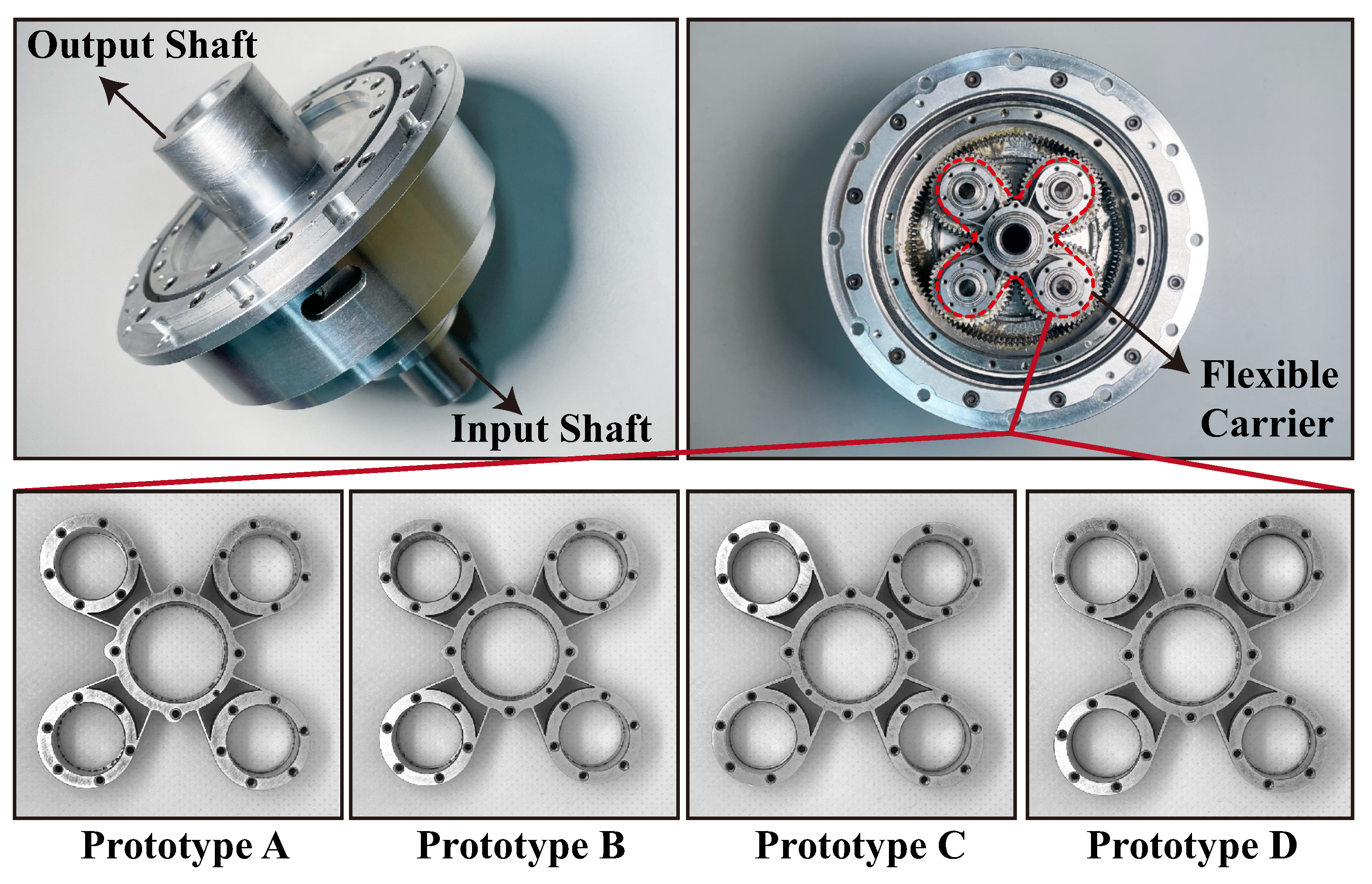
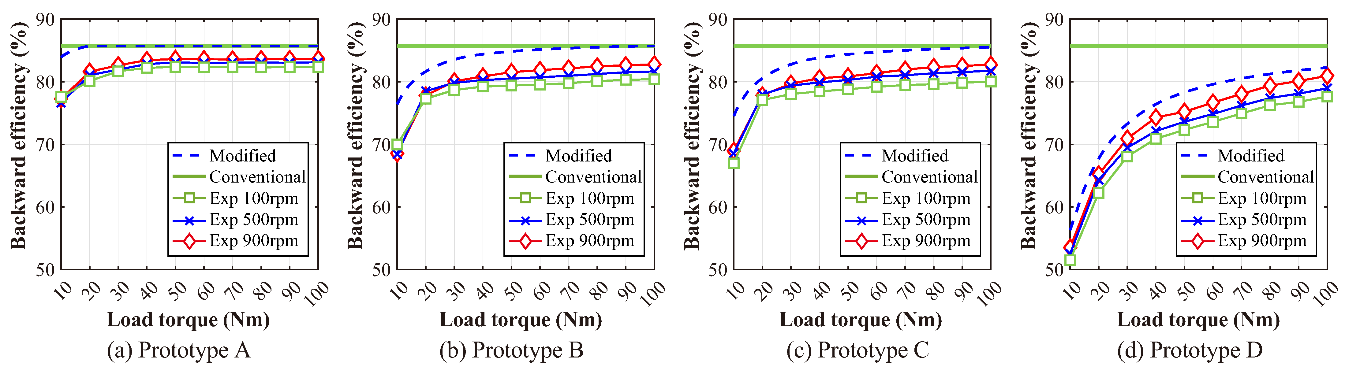
  • An anti-backlash 3K planetary gearbox prototype with four different carriers is fabricated and measured to validate the modified efficiency model, and the average errors between the predicted and the experimental results for forward and backward transmission efficiencies are 2.30% and 4.01%, respectively.
This article is organized as follows: The structures of the anti-backlash 3K planetary gearbox and the flexure-based carrier are described in Section 2. The quasi-static model considering the preloaded flexure-based carrier is established in Section 3. The meshing efficiency of the gear pair is corrected in Section 4 by considering the additional power loss introduced by reverse meshing forces in planet gears. The accuracy of the modified efficiency model is validated by experimental results in Section 5. Finally, Section 6 concludes this article.

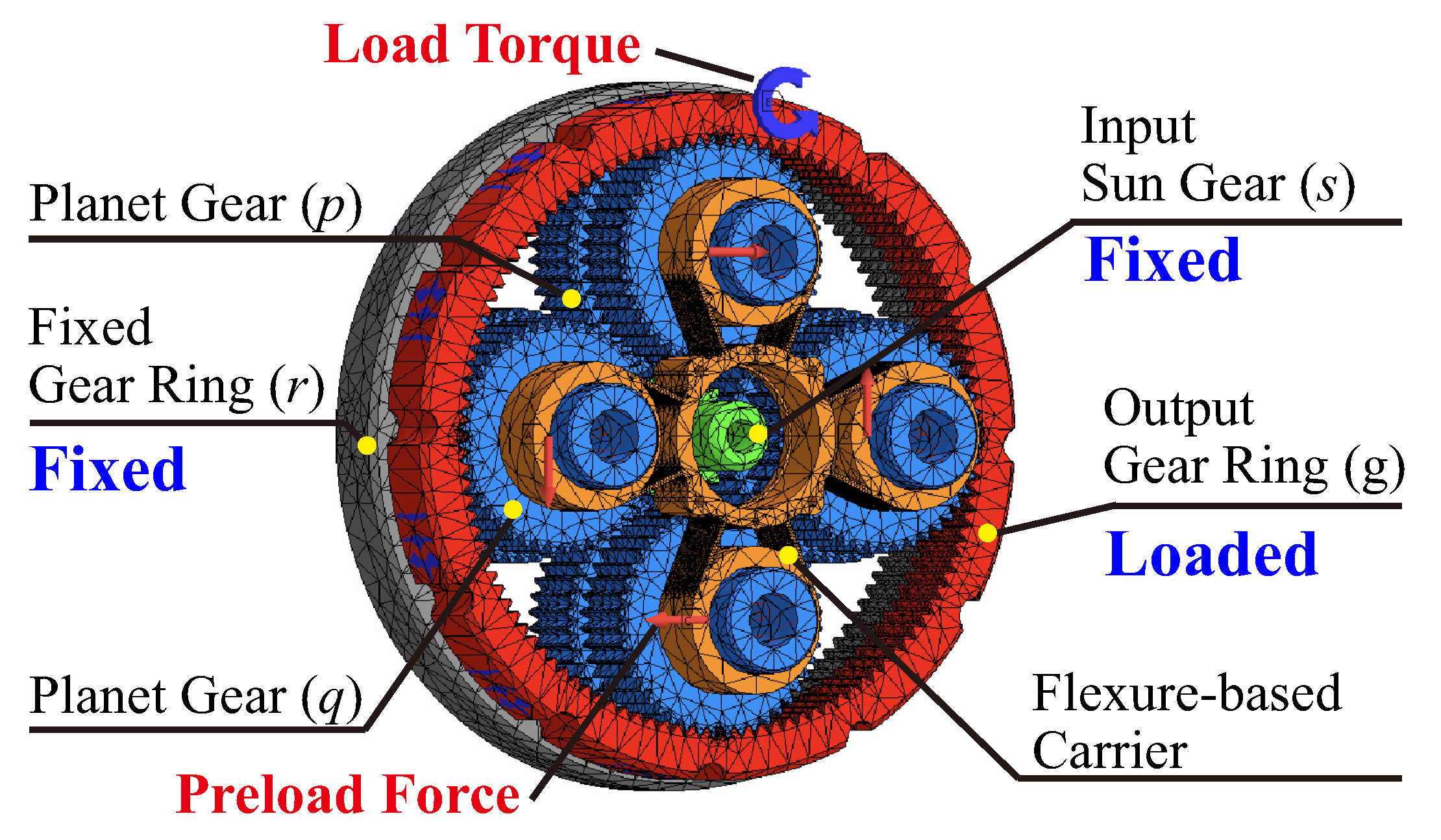
2. Description of Anti-Backlash 3K Planetary Gearbox with Flexure-Based Carrier

A high-precision compact anti-backlash 3K planetary gearbox is proposed in previous work, which eliminates the backlash with a preloaded flexure-based anti-backlash carrier. The structures of the 3K planetary gearbox and the carrier are introduced in this section.

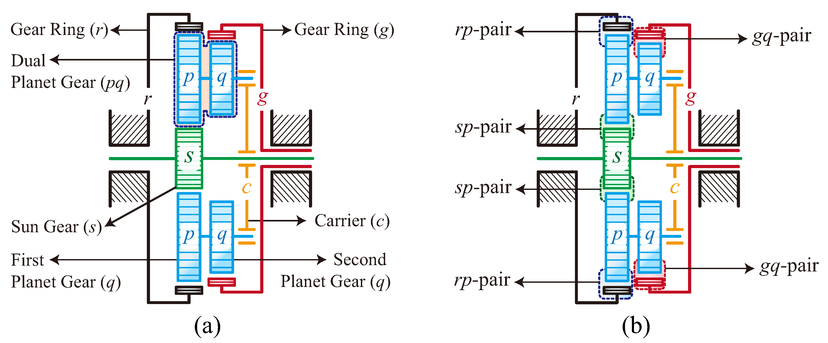
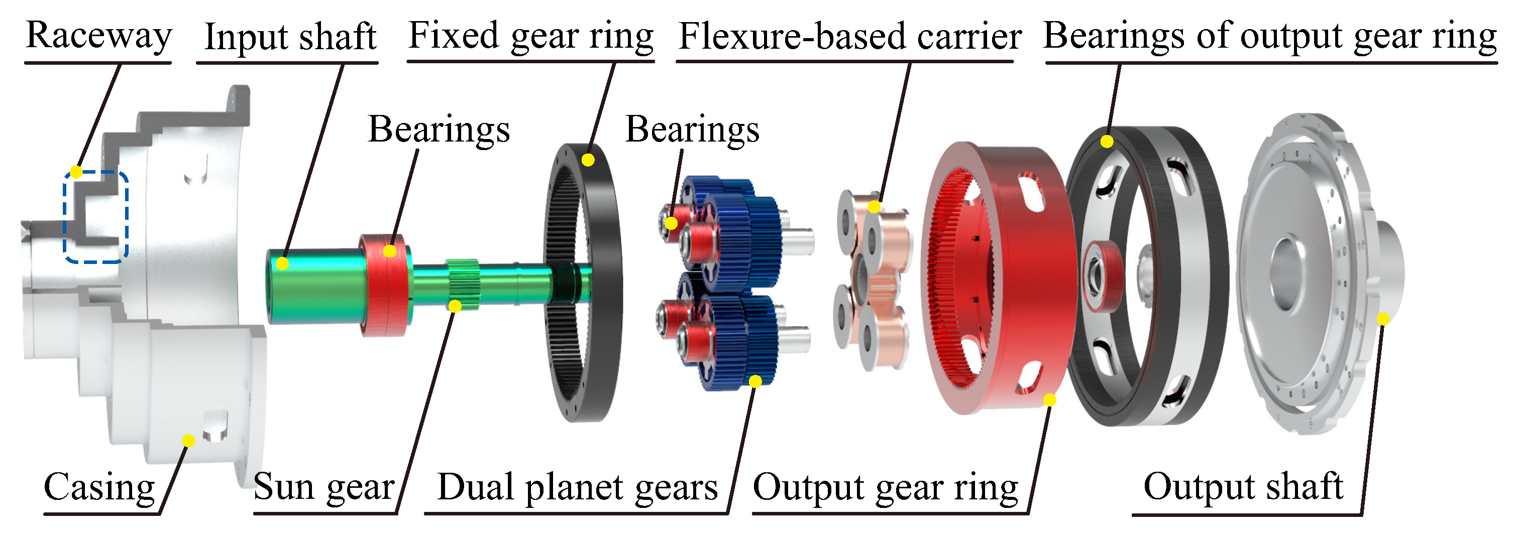
2.1. Structure of 3K Planetary Gearbox

As shown in Figure 1, the 3K planetary gearbox has a two-stage compound planetary gearbox configuration, which consists of three central gears (i.e., the sun gear s, and two gear rings r and g) and n dual planet gears (p and q) supported by the carrier c. The power between the two stages is transmitted by the dual planet gears, which implies that the carrier is not involved in the torque transmission but only supports the planet gears. In fact, the force analysis for the 3K planetary gearbox proves that the carrier is indeed not loaded with the tangential torque under the uniform velocity condition. In a typical design, the gear ring r is fixed with housing and the power is input by the sun gear s and output by the gear ring g, namely the 3K-I planetary gearbox.
These gears constitute one external gear pair (sp pair) and two inner gear pairs (rp pair and gq pair). For the 3K-I planetary gearbox, the gear ring r is fixed, and the reduction ratio of the 3K-I planetary gearbox can be derived based on Willis equations [32], which are given by:
i s g = 1 + z r z s 1 1 z r z q / ( z g z p ) .
where z j , j { s , r , g , p , q } are the tooth numbers of gears. From Equation (1), the reduction ratio is determined by the gear tooth numbers only. However, in a practical gearbox design with dimension limits, the gears in the first and second stages can take different modules to achieve the desired reduction ratio. The sign of the reduction ratio of the 3K-I planetary gearbox is determined by the gear tooth number. In this paper, the 3K-I planetary gearbox with a positive reduction ratio, i.e., z r z q < z g z p , is chosen as the main research object for its wide applications in robots. In addition, the reduction ratio of the 3K planetary gearbox can be enlarged by reducing the difference between z r z q and z g z p rather than increasing the tooth numbers of gear rings, which means the high reduction ratio can be achieved in a small volume for the 3K planetary gearbox. However, compared with the conventional reducers used in robot joints, such as harmonic drives and RV reducers, the transmission accuracy of the 3K planetary gearbox is relatively low due to the existence of considerable backlash.

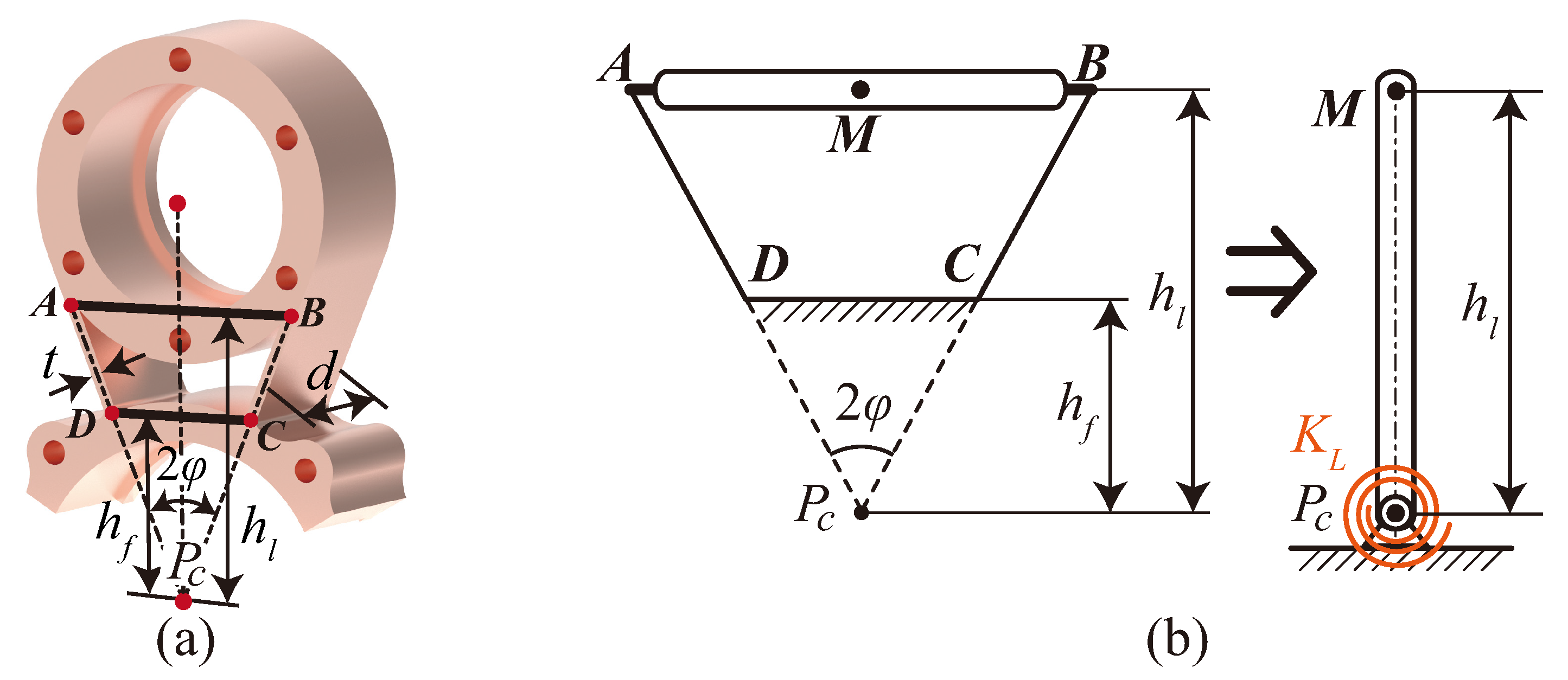
2.2. Structure of Flexure-Based Carrier

To eliminate the significant backlash and keep the compact structure of the 3K planetary gearbox simultaneously, a flexure-based anti-backlash carrier is proposed in previous work [8] utilizing the characteristic that the carrier of the 3K planetary gearbox normally is not loaded with tangential torque.
The structure of the flexure-based carrier is shown in Figure 2a. It consists of the central bearing housing and n planet bearing housings that are connected with the central part with the Leaf-type Isosceles-Trapezoidal Flexural Pivot (LITFP). As such, the planet bearing housings are allowed to rotate around the central part. Furthermore, the extended lines of all leaf springs intersect at the center point of carrier P c , which ensures that when the deflection of the carrier occurs, the rotation radiuses of the planet bearing housings are a constant value r c . The opening angles of the adjacent planet bearing housings are uneven, as shown in Figure 2, β is designed as slightly bigger than β , but the whole structure of the carrier is still symmetric.
As shown in Figure 2b, the carrier with the pre-designed opening angles repositions the planet gears and applies the preloads on the gear pairs. The two adjacent planet gears back-to-back mesh with the central gears under the preloads, and the backlashes of gear pairs can be eliminated, in which the adjacent planet gears are considered as an anti-backlash gear pair. According to the structure of the simplified flexure-based carrier, all the parameters of the carrier are pre-designed and nonadjustable. As such, it is significant to study the effects of the carrier’s key parameters (the opening angle and the supporting stiffness) on the 3K planetary gearbox.
The structure of the anti-backlash 3K planetary gearbox is illustrated in Figure 3. To achieve the proposed backlash reduction approach, four or a large even number of planet gears are necessary to ensure the symmetry of the 3K planetary gearbox. As collaborative robots usually have relatively low loading capacity, four planet gears are sufficient for power transmission. As such, we select four planet gears in our prototype design for the ease of fabrication and assembly. The raceway in the casing is designed to constrain the radial positions of planet gears. The effectiveness of the designed carrier in reducing backlash was validated in a previous study [8]. However, the effects of the preloaded flexure-based carrier on the transmission efficiency of the anti-backlash 3K planetary gearbox need to be further studied. To analyze the meshing behaviors of the anti-backlash 3K planetary gearbox, a quasi-static model is formulated in the next section.

3. Quasi-Static Model of Anti-Backlash 3K Planetary Gearbox

The preloaded carrier eliminates the backlash of the 3K planetary gearbox by repositioning its planet gears circumferentially, which also redistributes the loads between planet gears. Considering the speeds of planet gears are almost consistent, the load distributions between planet gears actually reflect the distribution of the branch powers. As such, a quasi-static model is formulated for the anti-backlash 3K planetary gearbox to analyze the effects of the carrier on the meshing forces.
As shown in Figure 4, the nonlinear quasi-static model considering the preloaded flexure-based carrier is established, where the carrier is treated as a preloaded flexible tangential supporting for planet gears. To simplify the quasi-static model, some assumptions are made as follows: (1) the supporting of the central components including the carrier, the sun gear, and two gear rings are all rigid; (2) the radial displacements of planet gears are neglected as the radial supporting stiffnesses for planets are much higher than the tangential direction; (3) all planet gears are identical to each other; (4) the manufacturing errors are neglected.

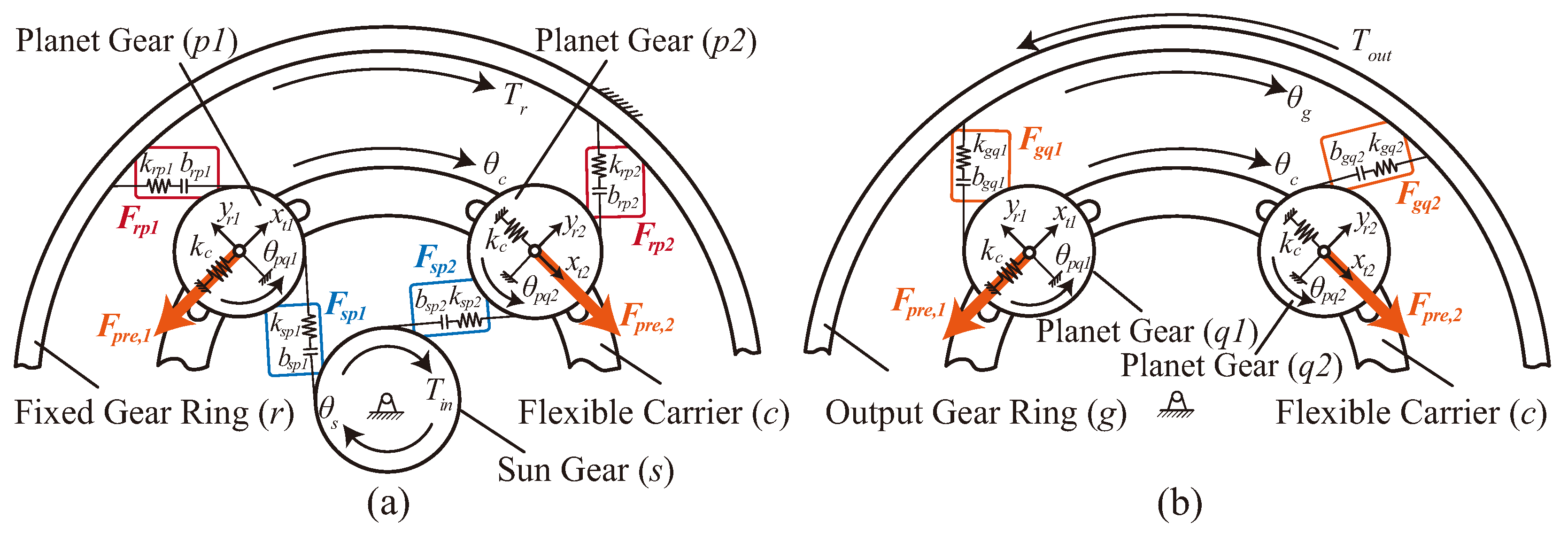
3.1. Force Balance Equations

For each component under the static state, the Force balance equations are established as follows:
Σ F s p i r b s T i n = 0 Σ F r p i r b r T r = 0 Σ F g q i r b g T o u t = 0 Σ F p q i r c = 0 F s p i r b p + F r p i r b p F g q i r b q = 0 k c x t i F p q i F p r e , i = 0
In Equation (2), r b j , j { s , r , g , p , q } and r c are the base circle radius of gears and the center distance of gear pairs, respectively. T i n , T r , and T o u t are the input torque, the reaction torque of the housing, and the load torque, respectively. F j , j { s p i , r p i , g q i } are the meshing forces of the i-th sp pair, rp pair, and gq pair, respectively. F p q i is the projection of the total meshing forces on the tangential direction of the i-th dual planet gear, which is given by:
F p q i = F s p i + F r p i F g q i cos α w ,
where α w is the working pressure angle of the gear pair. Significantly, in Equation (2), x t i is the tangential coordinate of the i-th dual planet gear. k c is the tangential supporting stiffness of the carrier and F p r e , i is the carrier’s preload on the i-th dual planet gear, which are the differences from the conventional model. The meshing forces and the preload of the carrier are determined as follows.

3.1.1. Meshing Forces

As shown in Figure 4, the meshing force of each gear pair F j , j { s p i , r p i , g q i } can be modeled as:
F j = k j f ( u j , b ) ,
where k j , j { s p , r p , g q } is the average meshing stiffness of each gear pair, which can be determined utilizing the Ishikawa method [33]. u j , j { s p i , r p i , g q i } are the relative displacements of two gears along the line of action of the gear pairs, which are respectively given by:
u s p i = r b s θ s r b p θ p q i ( r c θ c + x t i ) cos α w u r p i = r b p θ p q i r b r θ r ( r c θ c + x t i ) cos α w u g q i = r b q θ p q i r b g θ g + ( r c θ c + x t i ) cos α w
where θ j , j { s , r , g , p q i , c } are the rotation angle of each component. It is noted that for solving a static problem, the gears s and r are fixed and θ s and θ r are equal to zero when solving the equations.
Considering that the backlash exists in the gear pair, the dead zone model f ( u j , b ) is utilized in Equation (4), which is given by:
f ( u j , b ) = u j + b u j < b 0 b u j b u j b b < u j
where b is the half of backlash of each gear pair, which can be determined by the recommended value according to the center distance and the module of the gear pair.

3.1.2. Tangential Supporting Stiffness and Preload of the Flexure-Based Carrier

The stiffness of the carrier is determined based on the pin-joint model shown in Figure 5. The LITFP is equivalent to a revolute joint, and its flexibility is equivalent to a torsional spring at the pin center. The stiffness of the torsional spring was derived in Xu’s work [34], which is given by:
k L = 8 E I H cos φ h l h f 3 cos h l + 8 h f 8 h l h f Δ β ,
where E and I, respectively, are Young’s modulus and the moment of inertia, and H = h l 2 + h l h f + h f 2 , I = d t 3 / 12 . Other dimension parameters can be obtained according to Figure 5a. Δ β is the variation of the opening angle. As Δ β is very small, the stiffness of the carrier can be considered as a constant.
In the quasi-static model, the torsional stiffness of the LITFP of the carrier K L is equivalent to the tangential support stiffness k c for the dual planet gear, which can be expressed as:
k c = k L r c 2
where r c is the center distance of the gear pairs.
As the opening angle of carrier β is designed slightly larger than 2 π / n to reposition the adjacent planet gears so as to eliminate the backlash, the initial tangential coordinate of the i-th planet gear x i is given by:
x i = s g n β 2 π n r c , i [ 1 , n ]
where s g n is determined by the order of the planet gear. For the positive direction of the planet gear’s tangential displacement in Figure 4, s g n = 1 for planet gears at odd positions ( i = 1 , 3 , ) and s g n = 1 for the planet gears at even positions ( i = 2 , 4 , ). Consequently, the tangential supporting stiffness of the carrier and the nonzero initial tangential coordinates of the planet gears introduce generalized force terms into the static model, which are considered as the preloads of the flexure-based carrier. They are given by:
F p r e , i = k c x i , i [ 1 , n ]
Substitute Equations (3)–(10) into Equation (2), the quasi-static model of the anti-backlash 3K planetary gearbox considering the preloaded flexure-based carrier is established. The meshing forces of the anti-backlash 3K planetary gearbox are analyzed by solving the quasi-static model in the next subsection.

3.2. Meshing Forces of Anti-Backlash 3K Planetary Gearbox

To acquire the meshing forces of each gear pair in the anti-backlash planetary gearbox, the quasi-static model is solved by the trust-region algorithm under the different load torques T o u t . The anti-backlash 3K planetary gearbox with the optimized gear parameters developed in the previous work [8] is employed as a calculation case, and its parameters are listed in Table 1. The solved meshing forces are shown in Figure 6.
Furthermore, to validate the quasi-static model, the meshing forces of the anti-backlash 3K planetary gearbox are also simulated in Ansys Workbench 2021 R2.The simulated meshing forces based on the FEM model are also shown in Figure 6, and the FEM model is shown in Figure 7. The relative errors of meshing forces are 1.40%, 3.05%, and 1.04%, respectively, for sp, rp, and gq pairs, illustrating the quasi-static model is accurate. The minor errors are mainly caused by the inherent limitations of coarse mesh discretization in the FEM, and the unaccounted flexibilities in gear shafts within the quasi-static model.
The meshing forces of the gear pairs at diagonal positions are equal due to the completely symmetrical structure of the anti-backlash 3K planetary gearbox. And the meshing forces show piecewise characteristics under the light-load conditions, as positions of gear pairs relative to their backlash zone are changed by the preloaded flexure-based carrier.
Significantly, under light-load conditions, meshing forces of the sp2/sp4 pairs, rp2/rp4 pairs, and gq1/gq3 pairs are negative, namely reverse meshing forces. It means these pairs are meshing reversely and they actually impede power transmission. However, the meshing forces of the rp pair and gq pair increase rapidly with the increasing load torque, and reverse meshing forces in these pairs vanish accordingly, while the meshing forces of the sp pair are insensitive to the load torque due to the high reduction ratio. As a result, meshing forces of the sp2/sp4 pairs are always reverse within the range of the rated load torque shown in Figure 6. These reverse meshing forces mean that these branch gear pairs do not transmit effective power to the next-level gear but still generate friction power losses. It causes the additional power loss in the gear system, and the sp2/sp4 pairs are the main contributors obviously.
As the reverse meshing forces in gear pairs lead to additional power loss, the conventional transmission efficiency model of the 3K planetary gearbox needs to be modified for the anti-backlash 3K planetary gearbox, which is introduced in the next section.

4. Modified Transmission Efficiency Model of the Anti-Backlash 3K Planetary Gearbox

To establish a modified Bidirectional Transmission Efficiencies Model (BTEM) for the anti-backlash 3K planetary gearbox, the BTEM for a conventional 3K planetary gearbox is analyzed in this section firstly, and then the meshing efficiencies of gear pairs are corrected considering additional power losses due to the possible reverse meshing forces. The influence of the preloaded flexure-based carrier on transmission efficiency of the 3K planetary gearbox is studied by parametric analysis in this section.

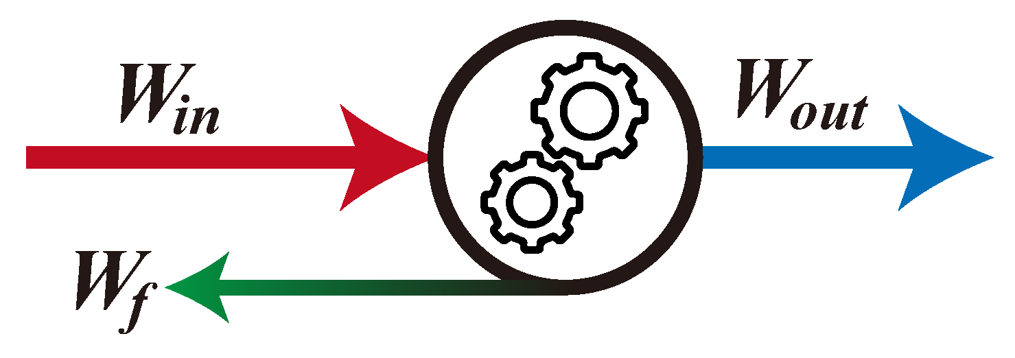
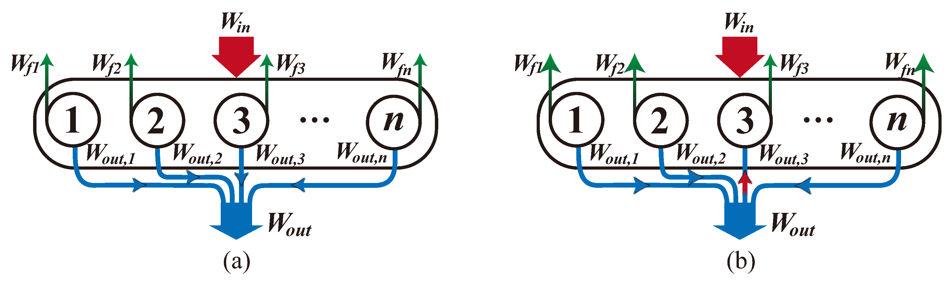
4.1. BTEM of Conventional 3K Planetary Gearbox

For the conventional 3K planetary gearbox, the BTEM was derived using the unit analysis method by Duan [27] and the dynamic relationship by Matsuki [4]. These models have the same formulation, shown as:
η i = 1 i 2 1 + i 1 · 1 + i 1 η s p η r p s g n 1 i 2 η g q η r p s g n s g n ,
where η i , i { f , b } , respectively, are the forward and backward transmission efficiencies of the 3K-I planetary gearbox, and s g n = 1 for η f , s g n = 1 for η b . The gear ratios of the first stage and the second stage, respectively, are i 1 = z r / z s and i 2 = z r z q / ( z g z p ) , where i 2 < 1 for the concerned 3K planetary gearbox.
As for the meshing efficiency η j , j { s p , r p , g q } in Equation (11), they can be acquired based on Muneharu’s equation [15], which is given by:
η j = 1 μ π z b ± z a z a z b ϵ a 2 + ϵ r 2 + 1 ϵ a ϵ r ,
where μ is the average coefficient of friction; ϵ a and ϵ r are the approach and recess contact ratios of the gear pair, respectively; z a and z b are the tooth numbers of the two gears, where a = s , p , q and b = p , r , g for s p , r p , and g q pairs, respectively. The positive sign is for the external gear pair and the negative sign is for the inner gear pair.
From the BTEM of the conventional 3K planetary gearbox, it is evident that both η f and η b are dependent on the gear ratios and the meshing efficiencies of gear pairs. The self-locking of the concerned 3K-I planetary gearbox occurs when η r p η g q < i 2 , which is undesired for backdriveable actuator designs. Even though, it has been demonstrated that the bidirectional efficiencies of the 3K planetary gearbox can be effectively improved by reducing the circulating power between two inner gear pairs and optimizing the contact ratios of gear pairs [4,27].
Obviously, the gear ratios are the same between the conventional and the anti-backlash 3K planetary gearbox with the same gear parameters, while due to the preloaded flexure-based carrier, the potential reverse meshing pairs cause additional friction power losses, and the meshing efficiencies of three types of gear pairs computed by Equation (12) are no longer accurate. Because the transmission efficiency of the high-reduction-ratio 3K planetary gearbox is highly sensitive to these meshing efficiencies [35,36], η j , j { s p , r p , g q } are corrected for the anti-backlash 3K planetary gearbox in the following subsection.

4.2. Corrected Meshing Efficiency for Anti-Backlash 3K Planetary Gearbox

Gear pairs with reverse meshing forces generate frictional power loss rather than transmitting effective power to the next level; they actually reduce the equivalent meshing efficiency of the corresponding type of gear pair. The meshing efficiencies are corrected in this subsection.
The power model of an individual gear pair is shown in Figure 8, where W i n , W o u t , and W f are the input power, the output power, and the friction power loss, respectively. According to the definition of the meshing efficiency, the relationship of these powers can be expressed as:
W f = W i n W o u t = ( 1 / η m 1 ) W o u t ,
where η m is the meshing efficiency calculated by Equation (12). It means the friction power loss is proportional to the output power when assuming the meshing efficiency is constant. While for a planetary gear system, each type of gear pair consists of n such gear pairs that transmit power in parallel and generate corresponding friction power losses. As such, the power model of a type of planetary gear pair with parallel branches is shown in Figure 9.
According to the definition of the efficiency, the meshing efficiency of a type of planetary gear pair consisting of n branches can be represented as:
η m p = W o u t W i n = Σ W o u t , i Σ W o u t , i + Σ W f i ,
where W o u t , i and W f i , i [ 1 , n ] , respectively, are the output power and the friction power loss of the i-th branch gear pair. Considering the speeds of these n branch gear pairs are equal, the branch output powers actually are proportional to the meshing forces of branches. When there is no reverse meshing force in the branches, substitute Equation (13) into Equation (14), η m p = η m can be obtained, while when negative meshing force exists, the calculation process needs to be modified.
As shown in Figure 9b, assuming the meshing force of the third branch is reverse, it means this branch not only generates the friction power loss but also impedes the output power. To achieve the same output power as shown in Figure 9a, other branches need to transmit more power to counteract the effect of the third branch, which also generates more friction power loss compared with the ideal situation as shown in Figure 9a. The output power of the third branch in this case can be considered “negative”, while its friction power loss is always a dissipation term. As such, the total meshing efficiency for this case should be expressed as:
η m p c = Σ W o u t , i Σ W o u t , i + Σ | W o u t , i | ( 1 / η m 1 ) = Σ F i Σ F i + Σ | F i | ( 1 / η m 1 ) ,
where F i , i [ 1 , n ] is the meshing force of i-th branch gear pair, η m p c is the corrected meshing efficiency considering the potential reverse meshing forces in branch gear pairs. When all F i are non-negative, Equation (15) is the same as Equation (14), while when negative F i exists, η m p c < η m can be obtained.
Replacing η j , j { s p , r p , g q } in the BTEM of the 3K planetary gearbox by the corrected meshing efficiencies η j c , j { s p , r p , g q } computed by Equation (15), the modified BTEM of the anti-backlash 3K planetary gearbox is established as:
η i c = 1 i 2 1 + i 1 · 1 + i 1 η s p c η r p c s g n 1 i 2 η g q c η r p c s g n s g n ,
where η i c , i { f , b } , respectively, are the modified forward and backward transmission efficiencies; the meanings and values of other parameters are the same as Equation (11). The effect of the preloaded flexure-based carrier on the transmission efficiencies of the 3K planetary gearbox is studied based on the modified BTEM in the next subsection.

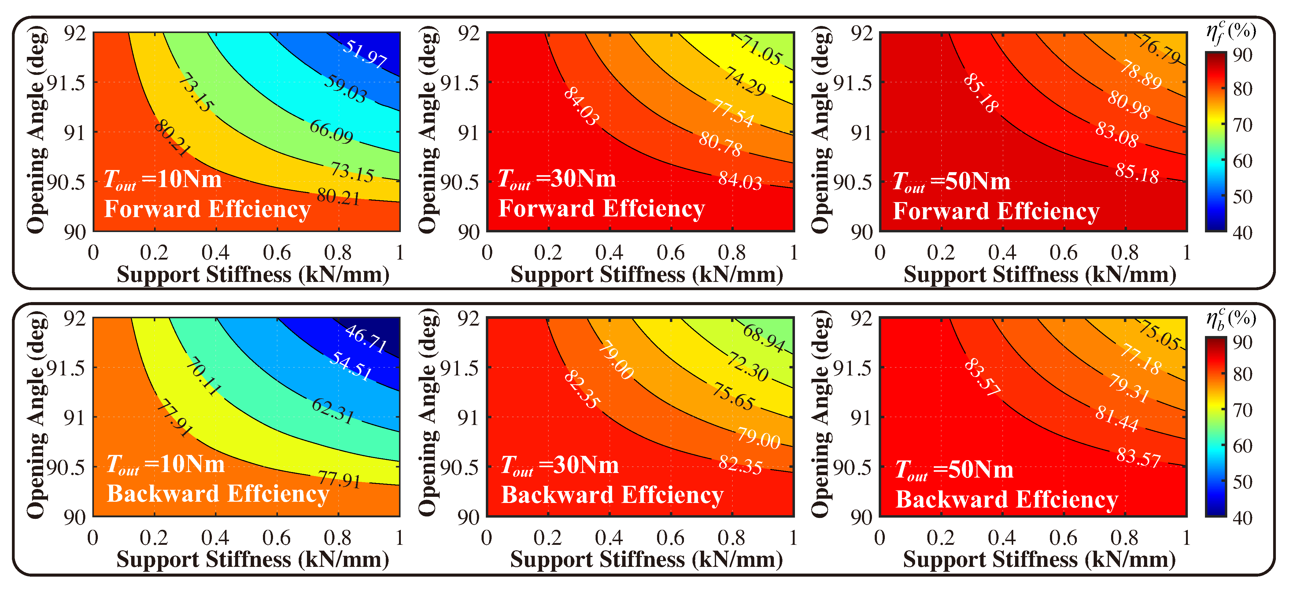
4.3. Effects of Flexure-Based Carrier on Transmission Efficiency

Based on the modified BTEM for the anti-backlash 3K planetary gearbox, the parametric analysis is conducted on the preloaded flexure-based carrier to study its effects on the transmission efficiency of the 3K planetary gearbox. The gear parameters listed in Table 1 are used, and the average friction coefficient of gear pairs is set as 0.12 according to previous works [4,6]. The opening angle of the carrier ranges from 90 to 92 , and the supporting stiffness of the carrier ranges from 0 to 1 kN/mm. Bidirectional transmission efficiencies of all cases are calculated under light-load conditions ranging from 10 Nm to 50 Nm. The calculated results are shown in Figure 10.
From the calculated results, conclusions are summarized as follows:
  • The bidirectional transmission efficiencies of an anti-backlash 3K planetary gearbox decrease with the increase in the preload of the flexure-based carrier, especially under the light-load condition.
  • The efficiencies increase as the load torque increases. It is because that high loads lead to the recovery deflection of the flexure-based carrier due to its compliance, which reduces the opening angle of the carrier and the absolute value of the reverse meshing forces decrease. This phenomenon is consistent with the meshing force analysis in Section 3.2.
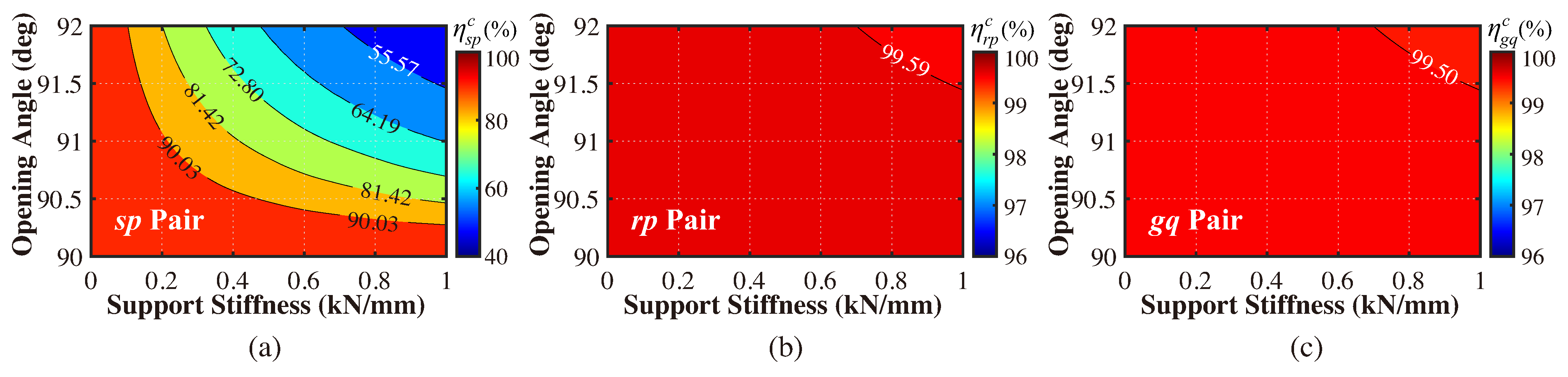
  • The backward transmission efficiency is slightly lower than the forward but always higher than 0, which means the flexure-based carrier cannot lead to the self-locking of the 3K planetary gearbox even under the high-preload condition. It is because the reverse meshing forces mainly exist in the sp pair, while the reverse meshing forces in rp and gq pairs vanish rapidly with the increasing of the load torque as shown in Figure 6. It illustrates the preload of a carrier mainly affects the meshing efficiency of the sp pair, rather than rp and gq pairs, as shown in Figure 11. Considering the self-locking of the 3K planetary gearbox only occurs when η r p c η g q c < i 2 from Equation (16), the preloaded flexure-based carrier does not affect the self-locking characteristic of the 3K planetary gearbox.
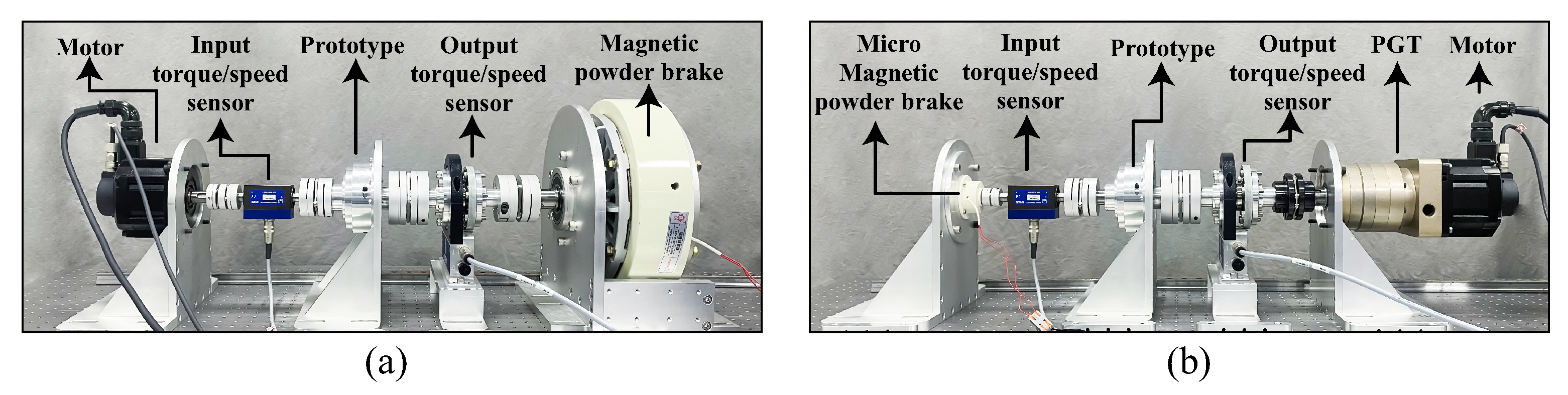
The modified BTEM for the anti-backlash 3K planetary gearbox is validated by experiments in the next section.

5. Experiments

To assess the accuracy of the modified efficiency model for the anti-backlash 3K planetary gearbox, four prototypes of the preloaded flexure-based carrier are fabricated and mounted in the 3K planetary gearbox, of which gear parameters are listed in Table 1. The critical parameters of the four carriers are listed in Table 2, and the width of the leaf springs t are designed according to the stiffness k c . Other parameters of carriers are identical for four prototypes as listed in Table 1, determined by the dimension parameters of gears and bearings.
The assemblies of the anti-backlash 3K planetary gearbox and four prototypes of the flexure-based carrier are shown in Figure 12. According to Equation (10), the preload of the flexure-based carrier is increasing from prototype A to D.
The testing benches for transmission efficiency are set up as shown in Figure 13. To acquire the concerned mechanical efficiency, as the method utilized in Talbot’s work [37], the spin power losses of the 3K planetary gearbox prototype with a standard rigid carrier under different speeds are measured firstly in unloaded conditions, and they were removed from the loaded measurement to isolate the mechanical power losses. Four sets of experiments are conducted on four prototypes. For each set, the forward and backward transmission efficiencies within the rated load torque range under various speeds are measured and compared with the computed results based on the modified BTEM. The results for forward and backward mechanical transmission efficiencies are presented in Figure 14 and Figure 15, respectively.
The experimental results indicate that increasing the preload of the carrier decreases the bidirectional transmission efficiencies of the anti-backlash 3K planetary gearbox, especially under light-load conditions, while transmission efficiencies improve rapidly as the load increases due to the compliance of the flexure-based carrier, which is consistent with the computed results. For prototype D, the preload of the carrier is so large that it is hardly practical for actual applications, nevertheless, the anti-backlash 3K planetary gearbox is still backdriveable, which validates the conclusion of the parametric analysis in Section 4.3. In addition, the increasing of the rotation speed slightly improves the mechanical transmission efficiency of the anti-backlash 3K planetary gearbox due to the improved lubrication [25,38].
The average errors of the predicted results by the conventional and modified BTEM compared with the experimental results are listed in Table 3.
For the conventional BTEM of the 3K planetary gearbox, the errors increase as the preload rises from prototype A to D, primarily because the effects of the preloaded flexure-based carrier are not accounted for. In contrast, for the modified BTEM proposed in this study, the average errors are consistently below 3% for forward transmission efficiencies and below 5% for backward transmission efficiencies. These results further validate the accuracy of the modified efficiency model for the anti-backlash 3K planetary gearbox. Compared to the conventional model, the average error of the modified model across the four prototypes is reduced from 5.91% to 2.30% for forward transmission efficiency and from 7.69% to 4.01% for backward transmission efficiency. The main predicted error sources of the modified efficiency model are probably the manufacturing errors and the neglecting of the bearing power loss. In addition, the errors of the backward efficiencies are slightly larger than the forward, which may be caused by the inconsistency of bidirectional meshing efficiencies of gears [39].
The results demonstrate that the modified efficiency model effectively predicts the impact of the preloaded flexure-based carrier on transmission efficiency. This model can be utilized for the design optimization of the flexure-based carrier.

6. Conclusions

In this paper, the bidirectional transmission efficiencies are analyzed for the anti-backlash 3K planetary gearbox with a preloaded flexure-based carrier by accounting for reverse meshing forces in planet gears. To analyze the effects of the carrier on the 3K planetary gearbox, a quasi-static model incorporating the carrier’s preload is established. The meshing forces of each gear pair are studied utilizing this quasi-static model, revealing that the reverse meshing forces in planet gears introduce the additional power loss into the gear system. By accounting for this power loss, a corrected meshing efficiency model is formulated for gear pairs, and the bidirectional transmission efficiencies of the anti-backlash 3K planetary gearbox are modified accordingly. The modified efficiency model is validated through experiments on four prototypes.
The results show that bidirectional efficiencies of the anti-backlash 3K planetary gearbox decrease with the increasing preload but increase rapidly with the rising load torque due to the compliance of the carrier, indicating that a flexible carrier can improve the transmission efficiency compared to a rigid carrier. It is also revealed that the preloaded carrier affects the transmission efficiency primarily by increasing the additional power loss of the sun–planet (sp) pair, rather than the other two inner gear pairs. This indicates that the design does not lead to self-locking of the 3K planetary gearbox, which is crucial for backdriveable robot joint actuators. The average errors between the predicted and experimental results are 2.30% for forward transmission efficiencies and 4.01% for backward transmission efficiencies, validating the accuracy of the modified efficiency model.
The proposed efficiency model is also promising to analyze the effects of other factors, such as manufacturing errors, on the transmission efficiency of the 3K planetary gearbox, which will be studied in our future work. The design optimization of anti-backlash 3K planetary gearboxes for backdriveable collaborative robot joints will be conducted based on the proposed efficiency model.

Author Contributions

Conceptualization, Q.D. and G.Y.; methodology, Q.D.; validation, Q.D. and W.W.; formal analysis, Q.D.; investigation, Q.D.; data curation, Q.D.; writing—original draft preparation, Q.D.; writing—review and editing, G.Y.; visualization, Q.D.; project administration, G.Y., C.-Y.C. and Z.F.; funding acquisition, G.Y. and W.W. All authors have read and agreed to the published version of the manuscript.

Funding

This work was supported by the National Natural Science Foundation of China (No. 92048201, No. U21A20121, and No. U20A20282), the Zhejiang Provincial Natural Science Foundation of China (No. LD24E050005), and Ningbo S&T Yongjiang 2035 Key Technology Program (No. 2024Z157).

Data Availability Statement

The data presented in this study are available on request from the corresponding author due to privacy.

Conflicts of Interest

The authors declare no conflicts of interest.

References

  1. Ishida, T.; Takanishi, A. A Robot Actuator Development with High Backdrivability. In Proceedings of the 2006 IEEE Conference on Robotics, Automation and Mechatronics, Bangkok, Thailand, 1–3 June 2006; pp. 1–6. [Google Scholar]
  2. Garcia, P.L.; Varadharajan, A.; Crispel, S.; Lefeber, D.; Verstraten, T.; Wikło, M.; Vasileiou, G. On the Potential of High-ratio Planetary Gearboxes for Next-generation Robotics. In Proceedings of the AGMA 2022 Fall Technical Meeting, Rosemont, IL, USA, 17–19 October 2022; pp. 50–63. [Google Scholar]
  3. Garcia, P.L.; Crispel, S.; Saerens, E.; Verstraten, T.; Lefeber, D. Compact Gearboxes for Modern Robotics: A Review. Front. Robot. 2020, 7, 103. [Google Scholar]
  4. Matsuki, H.; Nagano, K.; Fujimoto, Y. Bilateral Drive Gear—A Highly Backdrivable Reduction Gearbox for Robotic Actuators. IEEE/ASME Trans. Mechatronics 2019, 24, 2661–2673. [Google Scholar]
  5. Ling, Z.; Xiao, D.; Zhao, L.; Li, Y.; Ji, Z.; Xi, S.; Xia, X.; Zhou, Y. Self-lock Carrier: Realize Low-backlash Characteristic in 3K Planetary Gearbox. Adv. Mech. Eng. 2024, 16, 16878132241281079. [Google Scholar]
  6. Shin, W.; Ahn, B.; Kwon, S. A Low Backlash and Highly Efficient Gearbox for Robot Actuator. In Proceedings of the 2024 IEEE International Conference on Advanced Intelligent Mechatronics (AIM), Boston, MA, USA, 15–18 July 2024; pp. 224–229. [Google Scholar]
  7. Nandor, M.J.; Heebner, M.; Quinn, R.; Triolo, R.J.; Makowski, N.S. Transmission Comparison for Cooperative Robotic Applications. Actuators 2021, 10, 203. [Google Scholar] [CrossRef]
  8. Du, Q.; Zhang, T.; Yang, G.; Chen, C.Y.; Wang, W.; Zhang, C. A 3K Planetary Gear Train with a Flexure-based Anti-backlash Carrier for Collaborative Robots. Mech. Mach. Theory 2024, 191, 105495. [Google Scholar]
  9. Du, Q.; Zhang, T.; Yang, G.; Chen, C.Y.; Wang, W.; Zhang, C. Analytical Backlash Model for 3K-type Planetary Gear Train with Flexure-Based Anti-backlash Carrier. In Proceedings of the International Conference on Intelligent Robotics and Applications, Hangzhou, China, 5–7 July 2023; Springer: Singapore, 2023; pp. 384–397. [Google Scholar]
  10. Arnaudov, K.; Karaivanov, D.P. Planetary Gear Trains; CRC Press: Boca Raton, FL, USA, 2019. [Google Scholar]
  11. Tian, X.; Wang, G.; Jiang, Y. A New Calculation Method for Instantaneous Efficiency and Torque Fluctuation of Spur Gears. Stroj.-Vestn.-J. Mech. Eng. 2024, 70, 55–69. [Google Scholar]
  12. Yada, T. Review of Gear Efficiency Equation and Force Treatment. JSME Int. J. Ser. Dyn. Control. Robot. Des. Manuf. 1997, 40, 1–8. [Google Scholar] [CrossRef]
  13. Merritt, H.E. Gears: A Book of Reference for Engineers Concerned with the Design, Manufacture, Application or Maintenance of Gear Drives; Sir Isaac Pitman & Sons, Limited: London, UK, 1946. [Google Scholar]
  14. Buckingham, E. Analytical Mechanics of Gears; Courier Corporation: North Chelmsford, MA, USA, 1988. [Google Scholar]
  15. Muneharu, M. A Study of the Efficiency of the Planetary Gear Mechanism Applying the Mechanical Paradox Internal Gear. J. Fac. Eng. Shinshu Univ. 1979, 46, 1–12. [Google Scholar]
  16. Xu, X.; Chen, J.; Lin, Z.; Qiao, Y.; Chen, X.; Zhang, Y.; Xu, Y.; Li, Y. Optimization Design for the Planetary Gear Train of an Electric Vehicle under Uncertainties. Actuators 2022, 11, 49. [Google Scholar] [CrossRef]
  17. Li, C.; Qin, D.; Shi, W. Reference efficiency of planetary gear train. J. Chongqing Univ. 2006, 29, 11–14. [Google Scholar]
  18. Denny, C. Mesh Friction in Gearing; AGMA: Alexandria, VR, USA, 1998. [Google Scholar]
  19. Michlin, Y.; Myunster, V. Determination of Power Losses in Gear Transmissions with Rolling and Sliding Friction Incorporated. Mech. Mach. Theory 2002, 37, 167–174. [Google Scholar] [CrossRef]
  20. Xu, H.; Kahraman, A.; Anderson, N.; Maddock, D. Prediction of Mechanical Efficiency of Parallel-axis Gear Pairs. J. Mech. Des. 2007, 129, 58–68. [Google Scholar] [CrossRef]
  21. Li, S.; Kahraman, A. A Transient Mixed Elastohydrodynamic Lubrication Model for Spur Gear Pairs. J. Tribol. 2010, 132, 011501. [Google Scholar] [CrossRef]
  22. Li, S.; Kahraman, A. Prediction of Spur Gear Mechanical Power Losses Using a Transient Elastohydrodynamic Lubrication Model. Tribol. Trans. 2010, 53, 554–563. [Google Scholar] [CrossRef]
  23. Li, S.; Kahraman, A. A Method to Derive Friction and Rolling Power Loss Formulae for Mixed Elastohydrodynamic Lubrication. J. Adv. Mech. Des. Syst. Manuf. 2011, 5, 252–263. [Google Scholar] [CrossRef]
  24. Fernandes, C.M.; Martins, R.C.; Seabra, J.H. Coefficient of Friction Equation for Gears based on a Modified Hersey Parameter. Tribol. Int. 2016, 101, 204–217. [Google Scholar] [CrossRef]
  25. Blech, N.; Paschold, C.; Amar, L.; Lohner, T.; Tobie, T.; Stahl, K. Review of Different Calculation Approaches for the Mean Coefficient of Friction in ISO 6336. Forsch. Ingenieurwesen 2023, 87, 1169–1179. [Google Scholar] [CrossRef]
  26. Duan, Q.; Yang, S. A Fundamental Element Solution to Complicated Epicyclical Gear Trains. Mach. Des. Res. 2001, 17, 55–56+8. [Google Scholar]
  27. Duan, Q.; Yang, S. A Study on Power Flow and Meshing Efficiency of 3K Type Planetary Gear Train. Mech. Sci. Technol. 2002, 21, 360–362. [Google Scholar]
  28. Chen, L.F.; Wu, X.L.; Qin, D.T.; Wen, Z.J. Investigation on the Transmission Efficiency of the Planetary Gear Train. Appl. Mech. Mater. 2012, 103, 205–208. [Google Scholar] [CrossRef]
  29. Laus, L.; Simas, H.; Martins, D. Machine Efficiency Determined Using Graph and Screw Theories with Application in Robotics. Mech. Mach. Theory 2020, 148, 103748. [Google Scholar] [CrossRef]
  30. Li, J.; Hu, Q. Power Analysis and Efficiency Calculation of the Complex and Closed Planetary Gears Transmission. Energy Procedia 2016, 100, 423–433. [Google Scholar]
  31. Wang, C. The Effect of Planetary Gear/Star Gear on the Transmission Efficiency of Closed Differential Double Helical Gear Train. Proc. Inst. Mech. Eng. Part C J. Mech. Eng. Sci. 2020, 234, 4215–4223. [Google Scholar]
  32. Crispel, S.; García, P.L.; Saerens, E.; Varadharajan, A.; Verstraten, T.; Vanderborght, B.; Lefeber, D. A Novel Wolfrom-Based Gearbox for Robotic Actuators. IEEE/ASME Trans. Mechatronics 2021, 26, 1980–1988. [Google Scholar] [CrossRef]
  33. Shi, J.L.; Ma, X.G.; Xu, C.L.; Zang, S.J. Meshing stiffness analysis of gear using the Ishikawa method. Appl. Mech. Mater. 2013, 401, 203–206. [Google Scholar] [CrossRef]
  34. Xu, P.; Jingjun, Y.; Guanghua, Z.; Shusheng, B. The Stiffness Model of Leaf-Type Isosceles-Trapezoidal Flexural Pivots. J. Mech. Des. 2008, 130, 082303. [Google Scholar]
  35. Garcia, P.L.; Saerens, E.; Crispel, S.; Varadharajan, A.; Lefeber, D.; Verstraten, T. Factors influencing actuator’s backdrivability in human-centered robotics. MATEC Web Conf. 2022, 366, 01002. [Google Scholar]
  36. Varadharajan, A.; Garcia, P.L.; Crispel, S.; Vanderborght, B.; Lefeber, D.; Verstraten, T. Unconventional Gear Profiles in Planetary Gearboxes. In AGMA 2022 Fall Technical Meet; AGMA Foundation: Alexandria, VR, USA, 2022; pp. 40–49. [Google Scholar]
  37. Talbot, D.; Kahraman, A.; Singh, A. An Experimental Investigation of the Efficiency of Planetary Gear Sets. J. Mech. Des. 2012, 134, 7. [Google Scholar]
  38. Talbot, D.; Kahraman, A. A Methodology to Predict Power Losses of Planetary Gear Sets. In Proceedings of the International Gear Conference (Lyon-Villeurbanne), Lyon, France, 26–28 August 2014; pp. 26–28. [Google Scholar]
  39. Wang, A.; Kim, S. Directional Efficiency in Geared Transmissions: Characterization of Backdrivability towards Improved Proprioceptive Control. In Proceedings of the 2015 IEEE International Conference on Robotics and Automation (ICRA), Seattle, WA, USA, 26–30 May 2015; pp. 1055–1062. [Google Scholar]
Figure 1. Structure diagram of the 3K planetary gearbox: (a) components of the gearbox; (b) gear pairs of the gearbox.
Actuators 14 00173 g001
Figure 2. (a) Structure diagram of the flexure-based carrier; (b) eliminating backlash approach.
Actuators 14 00173 g002
Figure 3. Structure of the anti-backlash 3K planetary gearbox.
Actuators 14 00173 g003
Figure 4. Quasi-static model of the anti-backlash 3K planetary gearbox considering preloads of flexure-based carrier: (a) the first stage; (b) the second stage.
Actuators 14 00173 g004
Figure 5. Descriptions of the flexure-based carrier: (a) dimension parameters of the carrier; (b) equivalent pin-joint model of LITFP.
Actuators 14 00173 g005
Figure 6. Computed meshing forces by quasi-static model (QSM) and simulated meshing forces by FEM model (FEM): (a) sp-pair; (b) rp-pair; (c) gq-pair.
Actuators 14 00173 g006
Figure 7. FEM model of the anti-backlash 3K planetary gearbox built in Ansys 2021 R2.
Actuators 14 00173 g007
Figure 8. Power model of an individual gear pair.
Actuators 14 00173 g008
Figure 9. Power model of a planetary gear pair with branches: (a) without reverse meshing force branch; (b) with reverse meshing force branch.
Actuators 14 00173 g009
Figure 10. Bidirectional transmission efficiencies versus the parameters of the flexure-based carrier under the various loading torques.
Actuators 14 00173 g010
Figure 11. Corrected meshing efficiencies versus the parameters of the flexure-based carrier under the load torque of 10 Nm: (a) sp-pair; (b) rp-pair; (c) gq-pair.
Actuators 14 00173 g011
Figure 12. Prototypes of the anti-backlash 3K planetary gearbox with four flexure-based carriers.
Actuators 14 00173 g012
Figure 13. Testing benches for transmission efficiency measurements: (a) forward transmission efficiency; (b) backward transmission efficiency.
Actuators 14 00173 g013
Figure 14. Computed forward efficiencies by modified and conventional efficiency models vs. measured forward efficiencies: (a) Prototype A; (b) Prototype B; (c) Prototype C; (d) Prototype D.
Actuators 14 00173 g014
Figure 15. Computed backward efficiencies by modified and conventional efficiency models vs. measured backward efficiencies: (a) Prototype A; (b) Prototype B; (c) Prototype C; (d) Prototype D.
Actuators 14 00173 g015
Table 1. Parameters of the calculation case.
ParameterContentValue
z s Tooth number of the sun gear s24
z p Tooth number of the planet gear p48
z q Tooth number of the planet gear q44
z r Tooth number of the gear ring r120
z g Tooth number of the gear ring g116
nNumber of the dual planet gears4
k s p Average stiffness of the s p -pair271 N/ μ m
k r p Average stiffness of the r p -pair317 N/ μ m
k g q Average stiffness of the g q -pair315 N/ μ m
bHalf of the backlash30 μ m
α Pressure angle20 deg
α w Working pressure angle24.31 deg
mModule0.7 mm
EYoung’s modulus of the carrier71 GPa
dThickness of the carrier9.5 mm
β Opening angle of the carrier91 deg
tWidth of the leaf spring0.71 mm
h l Height of LITFP’s long side19.39 mm
h f Height of LITFP’s short side12.43 mm
φ Opening angle of the LITFP22.98 deg
Table 2. Key parameters of four prototypes of carriers.
Case OrderOpening Angle β Tangential Supporting Stiffness k c
A90.5 deg0.2 kN/mm
B91.5 deg0.2 kN/mm
C90.5 deg0.8 kN/mm
D91.5 deg0.8 kN/mm
Table 3. Average errors of predicted results by conventional and modified BTEM compared with experimental results.
Case OrderConventional Model (%)Modified Model (%)
ForwardBackwardForwardBackward
A1.863.651.653.43
B4.866.452.944.52
C5.036.792.484.22
D11.9113.882.143.88
Average5.917.692.304.01
Disclaimer/Publisher’s Note: The statements, opinions and data contained in all publications are solely those of the individual author(s) and contributor(s) and not of MDPI and/or the editor(s). MDPI and/or the editor(s) disclaim responsibility for any injury to people or property resulting from any ideas, methods, instructions or products referred to in the content.

