Abstract
In the plate-type permanent magnet electrodynamic suspension (PMEDS) vehicle, expansion joints in discrete conductive plates trigger the eddy current truncation effect, thereby causing an attenuation in the levitation force. To address this issue, a novel overlapped compensation structure is proposed, and its effectiveness is verified via simulation and experiment. First, the overlapped compensation structure and principle are introduced, followed by its theoretical model. Additionally, the comparative time-varying levitation force, along with its attenuation percentages, is analyzed under different guideways. Additionally, the optimal structure specifications covering overlapped thickness and length are studied, followed by a design guideline. In addition, dynamic analysis of a single bogie is carried out to analyze the effectiveness of the overlapped compensation structure in terms of vertical stability improvement. Lastly, the equivalent experiments are implemented to further confirm the proposed overlapped compensation structure. The experiment’s result reveals that compared to the original guideway expansion joint, the overlapped compensation structure can reduce levitation force attenuation by 20%. This work is expected to provide a reference for conductive plate guideway establishment in practical applications.
1. Introduction
The magnetic levitation (Maglev) technology [1,2] can be categorized into three types based on distinct levitation principles: electromagnetic suspension (EMS) [3,4], high-temperature superconducting magnetic levitation (HTS) [5,6,7], and electrodynamic suspension (EDS) [8]. Among these, permanent magnet electrodynamic suspension (PMEDS) [9,10,11] enables the levitation and guidance of vehicles through the interaction between permanent magnets and conductive plates. In addition, PMEDS is gaining significant attention in the industry due to its simple structure, great load-carrying capacity, and low cost. Substantial progress has been made globally in recent years. Notable developments include the Magplane, Magpipe, Inductrack [12,13], and the Hyperloop vacuum tube system proposed by Elon Musk [14,15,16]. PMEDS holds a wide range of application prospects in ultra-high-speed ground transportation and vacuum tube transportation.
However, the critical stability issue of the PMEDS system has emerged as a significant factor limiting its widespread application [17,18]. Due to the undamped characteristics, vehicle vibration inducements are common under levitation force fluctuation. This situation tends to deteriorate ride comfort and operational safety [19,20]. Although researchers have carried out in-depth analyses regarding the dynamics of the PMEDS vehicle [21,22,23,24], the time-varying characteristics of the levitation force have been largely disregarded, treating the levitation force as a constant value for input into the dynamic model. In practical applications, however, the levitation force is intrinsically time-varying, and expansion joints in discrete conductive plates represent one of the key contributing factors, which are analogous to rail expansion joints in high-speed railway ballasted tracks [25].
In engineering applications, the long guideway is composed of separate conductive plates, leading to the joints between the plates, which are designed to prevent the road sections from being damaged due to thermal expansion and contraction. The joints between the plates, aligned with the vehicle’s movement direction, are also uniformly referred to as expansion joints. When PMs traverse these expansion joints during guideway operation, the air gaps at the joints (where conductivity approaches zero) disrupt induced eddy current fields in the conductive plates, resulting in stepwise changes in levitation force. As the vehicle travels along an extended guideway, the expansion joints manifest periodically, leading to corresponding periodic variations in the levitation force. From an engineering perspective, expansion joints are essential for compensating for thermal expansion and contraction. However, from an electromagnetic standpoint, maintaining continuity between conductor plates is paramount.
There has been a dearth of research concerning the structural optimization of expansion joints and their impacts on PMEDS. T. D. Rossing et al. investigated the electromagnetic force in the PMEDS vehicle with respect to conductive plates [26]. However, there are two main limitations. Firstly, the comprehensive analysis of the influence exerted by expansion joints, along with experimental validation, remains deficient. Secondly, the kinetic analysis model predominantly centers on the electromagnetic force under steady-state conditions. Consequently, it is tough to comprehensively and accurately capture the time-dependent dynamic characteristics of the electromagnetic force, thereby restricting its guidance and reference in addressing this issue in the PMEDS vehicle.
To address this issue, a compensation structure is developed to mitigate levitation force reduction and fluctuations caused by guideway expansion joints, through theoretical modeling, simulation analysis employing time-varying levitation force characteristics, and experimental validation.
The subsequent sections are organized as follows: Section 2 presents the structural overview, principles, and theoretical model. Section 3 compares electromagnetic characteristics of different structures and optimizes the compensation structure. Section 4 conducts a dynamic comparative analysis to prove the superiority of the optimized compensation structure. Section 5 details the design and execution of equivalent experiments for different expansion joints. Finally, Section 6 concludes this work.
2. Structure and Principle
In this section, a concise introduction to the conventional straight joint structure is first provided. Subsequently, the overlap joint structure is proposed and systematically described. Then, an analysis of the PMEDS model with an overlap joint is conducted.
2.1. Structures of Expansion Joints
The PMEDS system comprises two primary components: permanent magnets (PMs) arranged in a Halbach array [27] and conductive plate guideways. When the PMs move above the conductive plate guideway at a specified speed, the strong magnetic field intersects the internal flux path of the conductive plate, inducing eddy currents within the plate. The magnetic field generated by these eddy currents opposes the variations in the source magnetic field, producing the levitation force above the conductive plate. This levitation force lifts the vehicle at a designated altitude above the guideway.
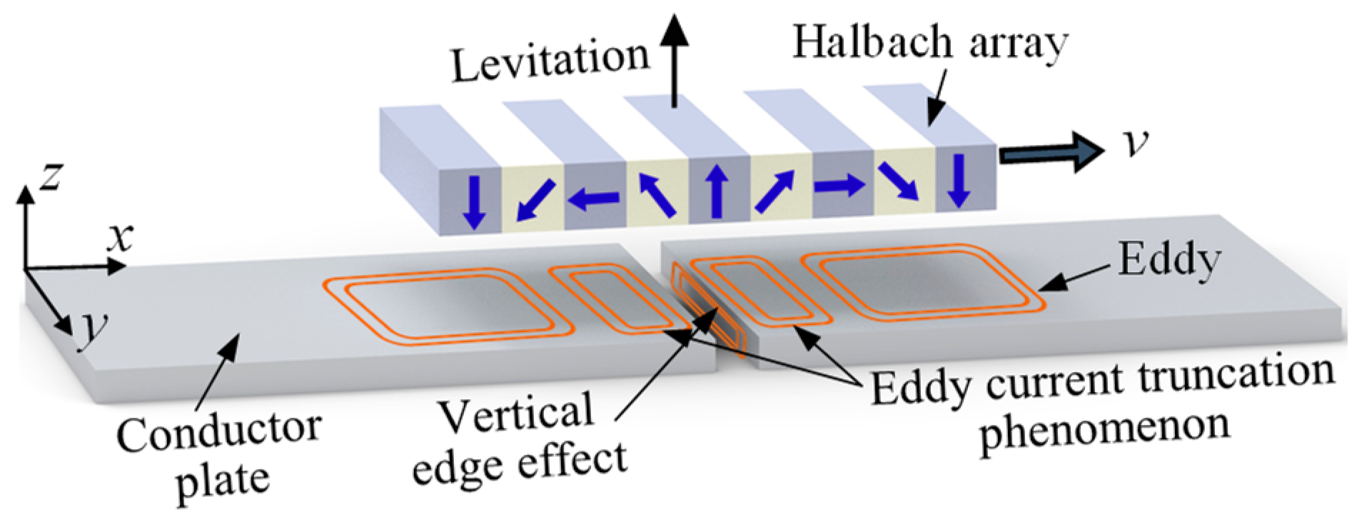
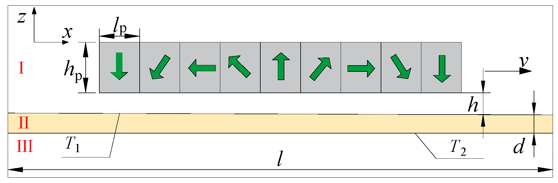
When the PMs operate within the continuous seamless region of the conductive plate, the induced eddy currents within the plate achieve a dynamic steady state, allowing the levitation force to remain balanced. However, in practical applications, the conductive plate length is always limited. This leads to straight seams where the eddy current is truncated, along with levitation force attenuation. This structure is illustrated in Figure 1 (hereinafter termed straight joint).
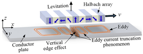
Figure 1.
Schematic diagram of the straight joint structure in the conductive plate.
Due to thermal expansion and contraction effects and limitations in plate processing, expansion joints in the conductive plate are inevitable. Hence, innovative compensation schemes for the conductive plate are required. These schemes should preserve the expansion joints to accommodate thermal expansion and contraction while minimizing the eddy current truncation effect.
Electromagnetically, the root cause of eddy current truncation is the discontinuity of the conductive plate at the expansion joint. Therefore, it is critical to achieve electrical connectivity with the conductor in this region. While welding is a straightforward and effective method for conductor connection, it undermines the function of expansion joints, failing to meet thermal expansion and contraction requirements. Adding a stacked plate above the expansion joint to establish an electrical connection is also unfeasible. If the stacked plate is too thin, the skin effect [28] prevents it from effectively connecting the conductive plates. Conversely, a thick stacked plate will reduce the levitation height, causing larger fluctuations in the levitation force.
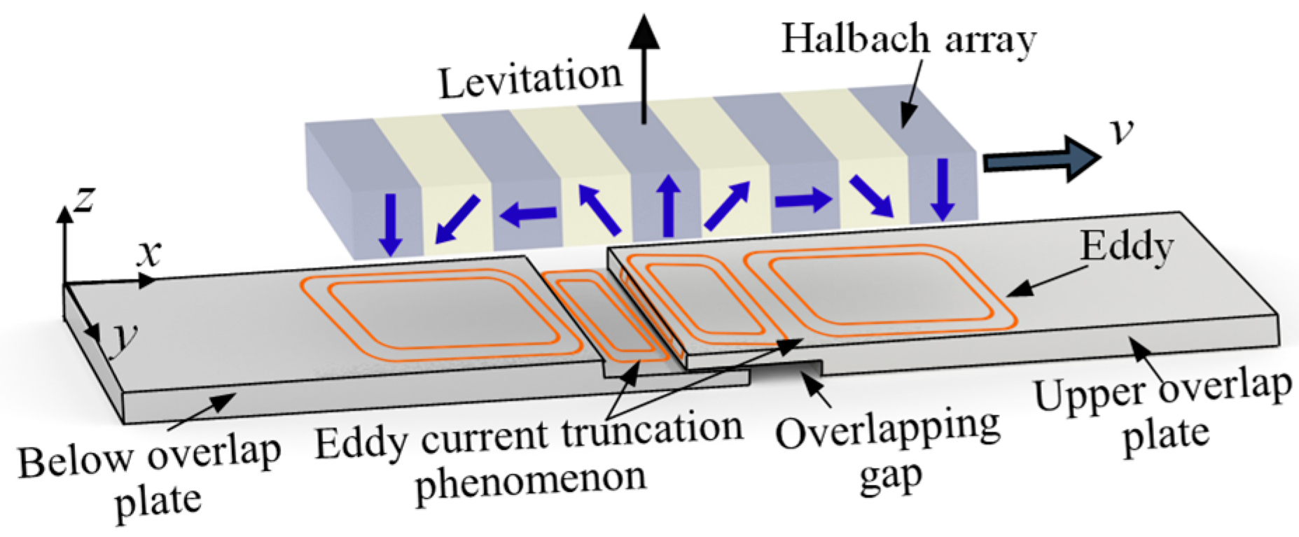
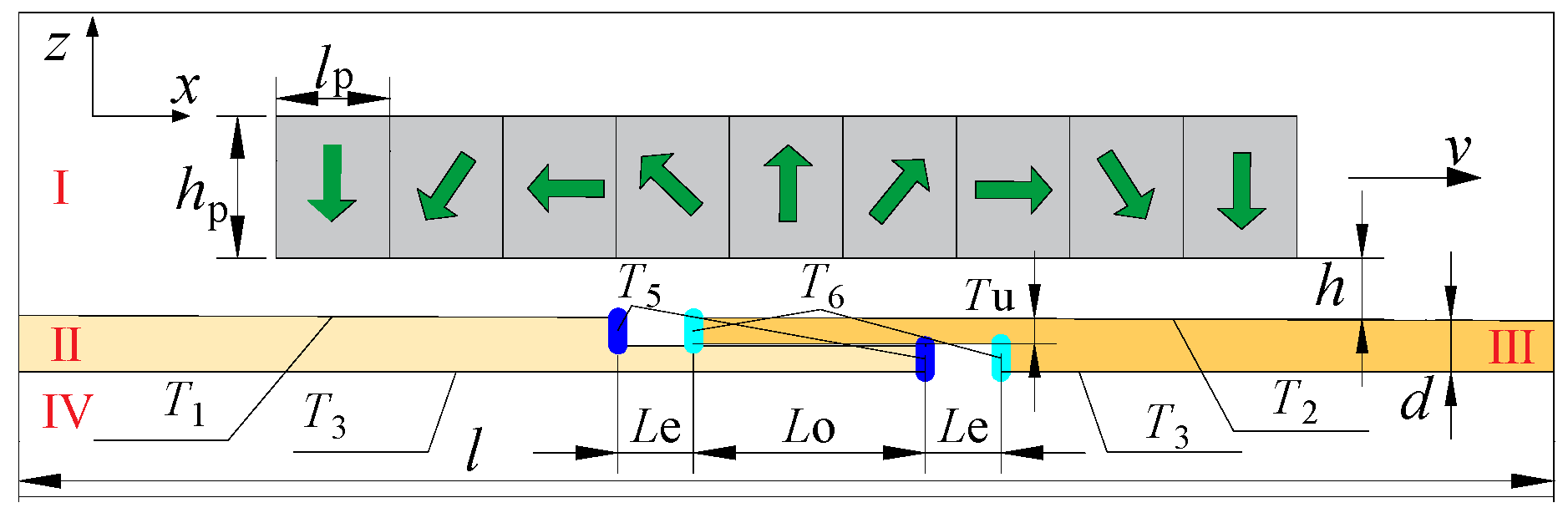
Based on the above analysis, this work presents the compensation structures to alleviate direct truncation at expansion joints and a compensation structure to ensure continuity there, as depicted in Figure 2. The joints of two conductive plates are staggered and overlapped (hereinafter termed overlap joint). This design effectively retains the original expansion and contraction joints to adapt to thermal fluctuations while ensuring the continuity of eddy currents between the conductor plates.
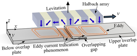
Figure 2.
Schematic diagram of the overlap joint structure in the conductive plate.
2.2. Analytical Model of PMEDS with Overlapped Compensation Structure
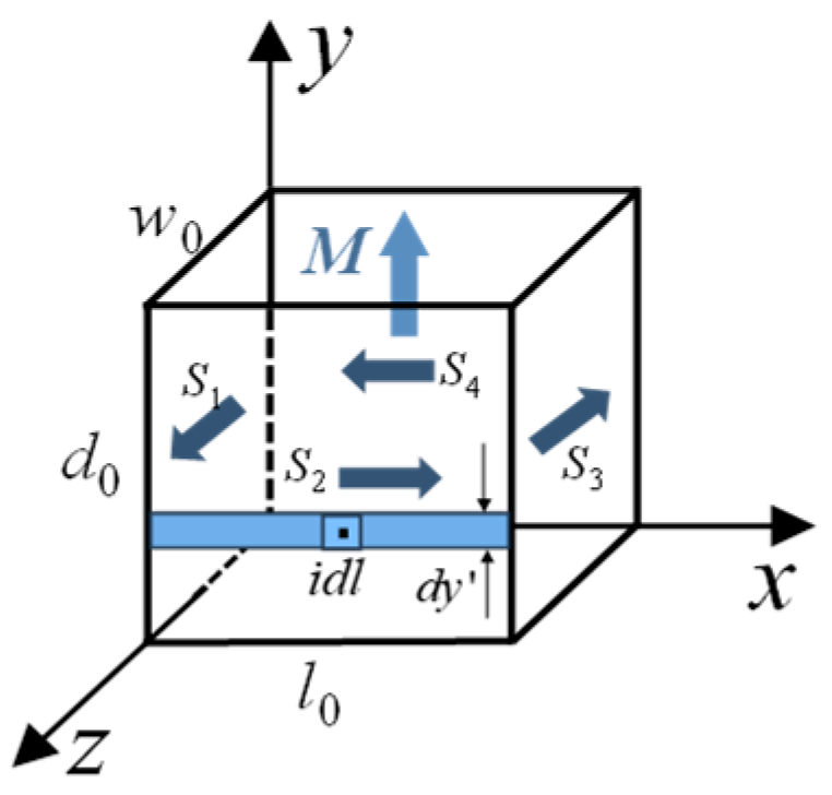
First, the surface current method is used to calculate the magnetic field of the permanent magnet. As shown in Figure 3, where arrow M is the direction of magnetization and arrows S are the direction of surface currents. This method utilizes the Ampere molecular circulation assumption to magnetize the permanent magnet vertically by assuming that it consists of a series of surface current magnetic fields. According to the principle of linear superposition, the magnetic field at a point in space is a superposition of the magnetic fields generated by each surface current element.

Figure 3.
Permanent magnet surface current assumption.
From Maxwell’s equations, the governing equations for the magnetic vector potential in the permanent magnet surface current region () and air domain surrounding the permanent magnet () are given by Equation (1), where Br denotes the remanent flux density of PMs [29].
Figure 4 illustrates the PMEDS configuration with a complete conductive plate, where region I denotes the upper air domain above the conductive plate, region III represents the lower air domain beneath the conductive plate, and region II corresponds to the conductive plate itself. The geometric parameters are defined as follows: permanent magnet length (lp), permanent magnet thickness (hp), levitation height (h), conductive plate thickness (d), with T1 and T2 indicating the upper and lower surfaces of the conductive plate, respectively.
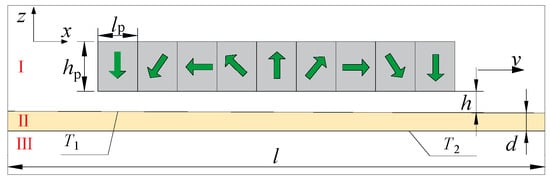
Figure 4.
Schematic of PMEDS configuration with complete conductive plate.
Given that the PMs move at a speed significantly lower than the speed of light and the displacement current is negligible, the model can be analyzed under the quasi-static field assumption, with vertical eddy currents assumed negligible. Assuming an infinitely extended computational domain and the application of Dirichlet boundary conditions, the governing equations for each region in the quasi-static regime are formulated in Equation (2) [30].
where μ0 represents the vacuum permeability, and σ denotes the conductivity of the conductive plate. The analysis focuses on the magnetic field at the conductive plate surface, which is solved using the separation of variables method. The relationship between the magnetic flux density (B) and the magnetic vector potential (A), as defined in Equation (3), enables the derivation of the resultant magnetic field across the computational domain. The levitation force (Fl) is computed via Maxwell’s stress tensor formulation [31], as expressed in Equation (4).
At elevated speed, the increased spatial frequency of the magnetic field induces a pronounced skin effect, thereby reducing the penetration depth of eddy currents into the conductive plate. This results in an effective conductivity lower than the nominal value σ0. The corrective formulation for the conductivity of the conductive plate under skin effect is derived as Equation (5) [32].
where d denotes the conductive plate thickness, τ indicates the magnetic pole pitch, and δ represents the skin depth. The modified conductivity of the conductive plate, σ1, is obtained as in Equation (6).
The analytical model for the electromagnetic characteristics of PMEDS with an overlap joint is constructed as follows, with its schematic configuration shown in Figure 5. A minor gap is intentionally introduced along the z-direction between the contact surfaces of the upper and lower overlap plates to maintain electrical insulation between them. Key geometric parameters governing the overlap joint configuration of the conductor plate include the length of expansion joint (Le), the length of overlap (Lo), and the thickness of the upper overlap plate (Tu).

Figure 5.
Schematic of PMEDS configuration with an overlap joint.
In contrast to the infinite conductive plate assumption, the overlap joint model requires explicit consideration of longitudinal edge effects. Although the governing field equations maintain structural equivalence, geometric segmentation of the conductor plate into distinct regions II and III with potential conductivity variations necessitates region-specific differential formulations. Discretization is implemented separately for each domain. Given the interfacial complexity at expansion joints, electromagnetic force computation via the stress tensor method becomes computationally intractable, thus justifying the Lorentz force method for levitation force determination, as shown in Equation (7).
The current density J is explicitly defined by Equation (8).
Under the assumption of negligible vertical eddy current components, Fl is formulated as Equation (9).
The critical geometric parameters of the overlap joint configuration (Le, Lo, Tu in Figure 5), fundamentally govern the electromagnetic characteristics in PMEDS.
3. Electromagnetic Characteristics and Optimization of Overlapped Compensation
This section evaluates the compensation efficacy through comparative electromagnetic analysis of straight joint versus overlap joint, followed by the parametric optimization of critical geometric parameters, specifically (Le, Lo, Tu) in the overlap joint structure.
3.1. Effectiveness Analysis of Overlapped Compensation Structure

Table 1.
Specific parameters of expansion joints models.
The initial analysis focuses on the straight joint model. The levitation force of this configuration is obtained by solving the partial differential equation in Equation (2) using finite difference method. Figure 6 presents the time-domain characteristics of the levitation force when the Halbach array traverses the expansion joint in the straight joint model at 250 km/h (Le: 10–80 mm). As the Halbach array crosses the expansion joint region, a sharp decay in levitation force is observed, followed by rapid recovery to baseline levels upon exiting. Specifically, each joint crossing induces at least two pronounced fluctuations in levitation force. Notably, weak longitudinal edge effects from the leading conductive plate during the Halbach array’s traversal result in slight asymmetry in the time-domain levitation force profile. When the Halbach array approaches the straight joint, abrupt magnetic field changes induce stronger eddy currents, akin to a sudden surge in friction during emergency braking. When moving away from the straight joint, although the magnetic field variation is symmetric, residual eddy currents require time to decay (similar to the gradual dissipation of residual heat after brake release). The difference in physical mechanisms between the “generation-decay” processes causes the force–time curve to exhibit a weakly asymmetric profile. As the Le increases, the magnetic field distortion zone expands, equivalent to prolonging the “brake pad contact time,” which amplifies the asymmetric characteristics. Through periodic extension of these fluctuation trends, the operational levitation force behavior can be predicted with enhanced accuracy. For straight joint guideways, long-term levitation force dynamics exhibit cyclical fluctuation patterns in the time domain.
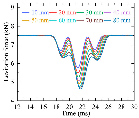
Figure 6.
Time-domain levitation force characteristics in a straight joint under varying lengths of the expansion joint.
To quantitatively characterize levitation force attenuation during PMs traversal across expansion joints, the levitation force attenuation rate (LAR) is defined as in Equation (10):
where Fl denotes steady-state levitation force and Flmin represents the minimum force when the Halbach array traverses the expansion joint. This metric quantifies transient levitation force reduction.
Figure 7 illustrates the variation in LAR for a straight joint with different Le values (10–80 mm) across speed ranges of 100–600 km/h. The results demonstrate that Le variations exert a significant influence on LAR. Under constant speed, the levitation force exhibits more pronounced decay with increased Le. Notably, at the maximum tested speed of 600 km/h, the LAR surged from 22% to 38% as Le increased from 10 mm to 80 mm. For fixed Le values, although the trend is less prominent, LAR decreases with rising speed; specifically, at the maximum Le (80 mm), the decay rate declined from 44% to 38% as speed increased from 100 km/h to 600 km/h. Under a straight joint structure, the abrupt fluctuation of levitation force that occurs when the PMs traverse expansion joints induce vertical vibrations, substantially degrading the levitation stability.
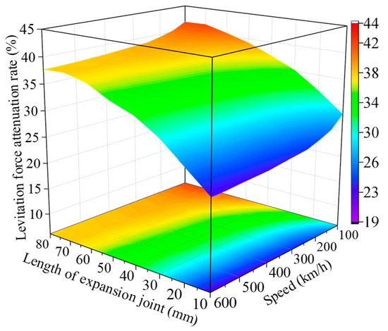
Figure 7.
Dependence of the levitation force attenuation rate on the length of the expansion joint at speeds of 100–600 km/h.
A comparative analysis of time-domain levitation force characteristics was conducted for two expansion joint types in the PMEDS. Simulations maintained identical critical parameters except for joint configuration. As shown in Figure 8, taking Le = 10 mm and 250 km/h as a representative case, the time-domain response curves demonstrate distinct levitation force behaviors between joint configurations.
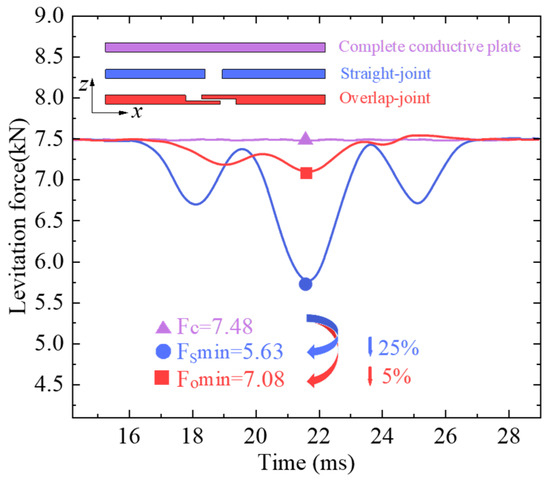
Figure 8.
Comparison of the time-domain curves of the levitation force under different expansion joints.
At time = 22 ms, when the center of the Halbach array aligns with the symmetric center of the expansion joints, the levitation forces for both joint configurations reach their minimum values. As shown in Figure 8, the levitation force time-domain curve of the overlap joint exhibits strong asymmetry relative to the time = 22 ms line. This asymmetry arises because, as the Halbach array traverses the overlap joint in the positive x-direction, the actual levitation height at the right-side overlap joint is greater than that at the left-side joint, resulting in more pronounced attenuation of the levitation force on the left side. Due to the strict left–right symmetry of the Halbach array, reversing the configuration (placing the upper overlap plate on the left and the lower overlap plate on the right) would induce a mirror reversal of the time-domain levitation force curve for the overlap joint.
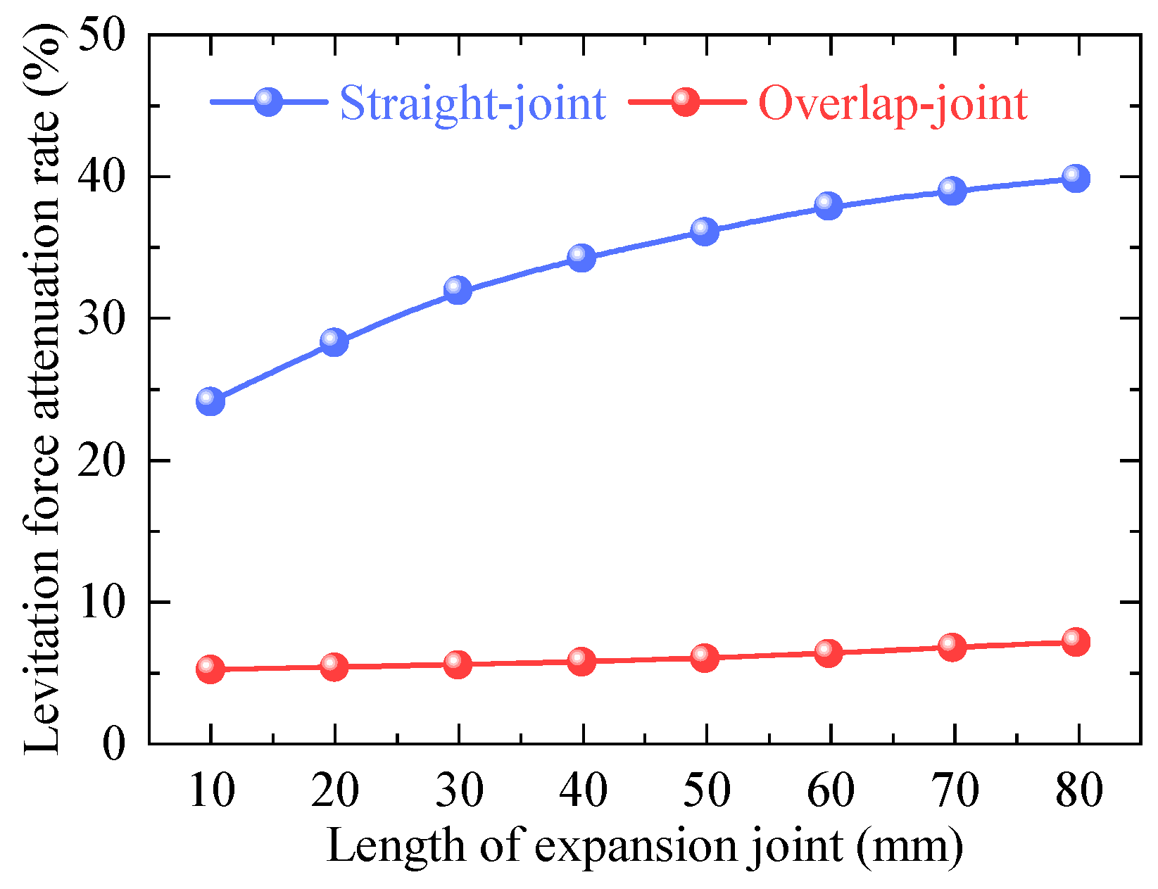
The results reveal that the overlap joint exhibits significantly reduced LAR compared to the straight joint structure, with measured LAR values of 5% and 25%, respectively. This 80% reduction in force attenuation highlights the effectiveness of the overlap joint design in maintaining levitation stability while traversing the expansion joint.
Figure 9 compares the LAR trends of two joint configurations under varying Le (10–80 mm) at 250 km/h. The overlap joint consistently exhibits lower LAR values than the straight joint across all tested Le ranges, and with a significantly attenuated growth rate of LAR as Le increases. This improvement is primarily attributed to optimized eddy current continuity at joint interfaces during PMs traversing the expansion joint.
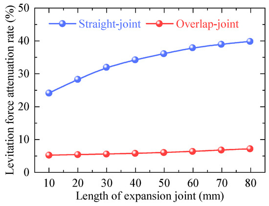
Figure 9.
Evolution of the levitation force attenuation rate with the length of the expansion joint under different expansion joints.
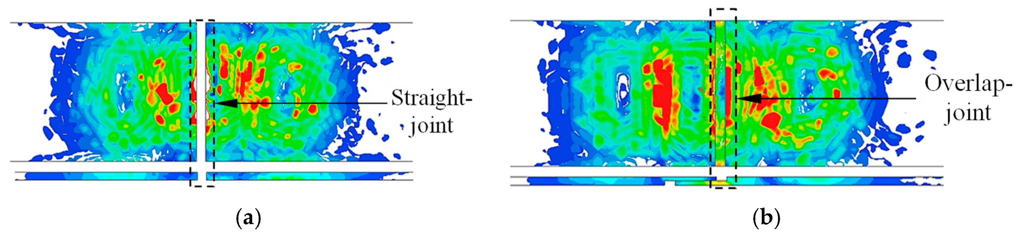
Figure 10 illustrates the eddy current distribution characteristics at expansion joints for two distinct configurations. In the straight joint configuration, the gap induces abrupt truncation of eddy currents within the conductive plate, leading to significant transient fluctuations in the levitation force. Conversely, the overlap joint facilitates sequential eddy current transfer between adjacent plates: as eddy currents attenuate in the leading plate, the trailing plate dynamically generates compensating currents. This mechanism preserves eddy current continuity across the joint interface, thereby stabilizing the induced magnetic field.
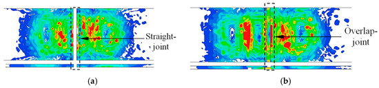
Figure 10.
Eddy current distribution at expansion joints on conductor plate: (a) Straight joint; (b) Overlap joint.
It is worth noting that while spherical scatterers may optimize eddy current distribution by dispersing concentrated eddy current zones, as demonstrated in prior research [33,34], their relatively high costs render them unsuitable for eddy current optimization in PMEDS expansion joints.
3.2. Analysis and Optimization of Length of Expansion Joint
The determination of Le requires rigorous consideration of material thermal expansion properties. At minimum temperatures, Le must be configured to accommodate maximal thermal expansion. When assessing Le’s influence on the LAR in the overlap joint, the pole pitch of PMs emerges as a critical coupled parameter. Variations in pole pitch directly modulate the longitudinal distribution of induced eddy currents within the conductive plate.
As illustrated in Figure 11, LAR exhibits progressive elevation with increasing Le, though this trend is significantly mitigated by larger pole pitch configurations. Extended pole pitch enhances eddy current articulation through elongated spatial distribution of induced currents, reducing flux density discontinuities at joint interfaces and thereby attenuating LAR growth rates.
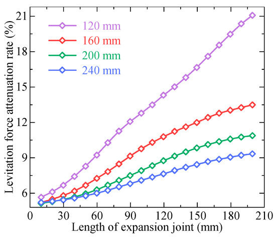
Figure 11.
Evolution of levitation force attenuation rate with the length of the expansion joint in the overlap joint under varied pole pitches of PMs.
The optimization of Le necessitates balancing conductive plate thermal expansion requirements with levitation force performance. Le must compensate for thermally induced displacements while maintaining minimal dimensions to prevent eddy current discontinuity effects. Concurrently, the enlargement of the pole pitch of PMs enables LAR reduction, which counteracts the levitation force attenuation caused by Le extension, ultimately improving the electromagnetic performance of the overlap joint.
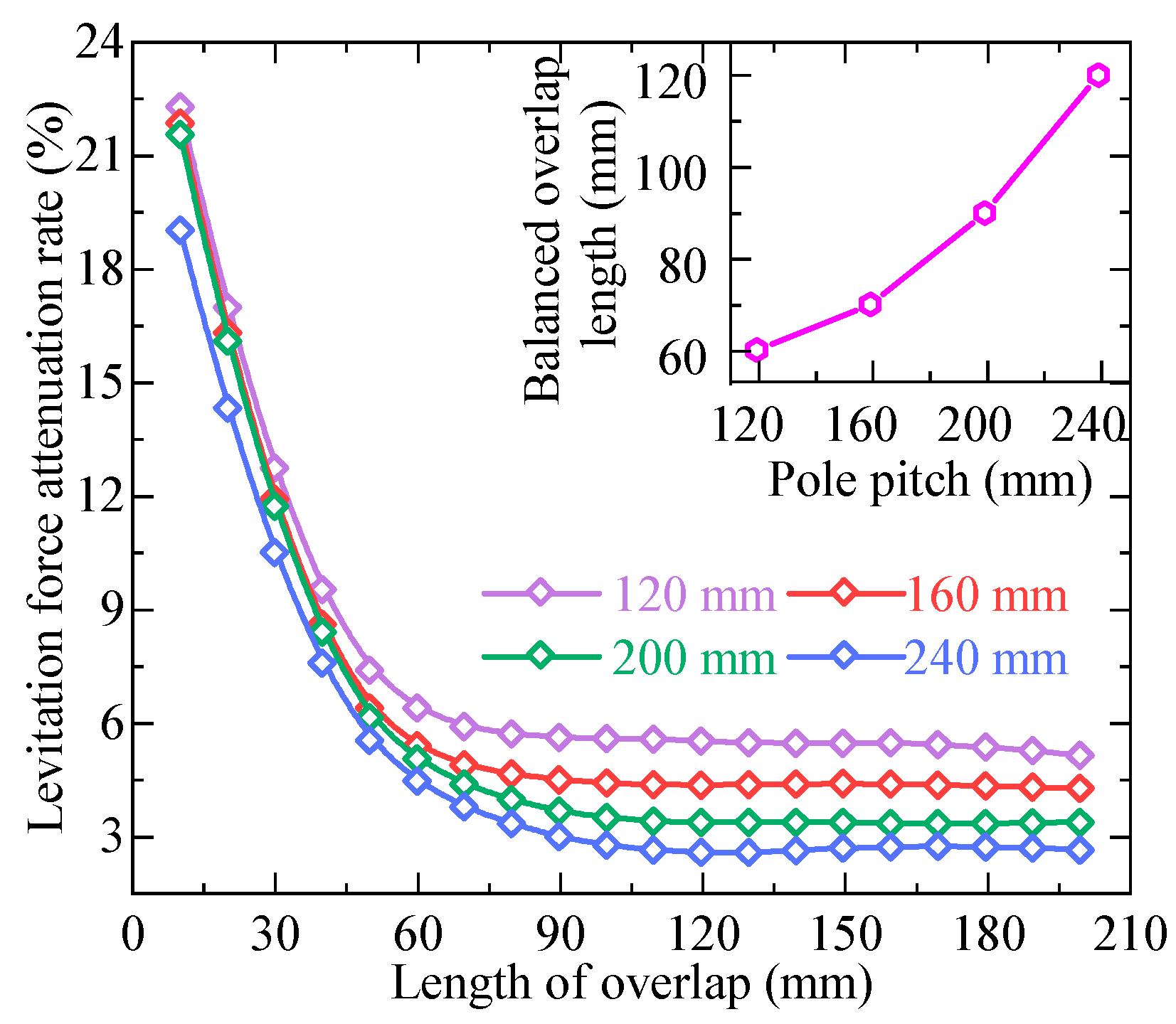
3.3. Analysis and Optimization of the Length of the Overlap
During Lo analysis, the influence of the pole pitch of PM variations is incorporated into electromagnetic simulations. Figure 12 demonstrates LAR progression with increasing Lo across different pole pitches. The LAR exhibits an initial decrease followed by stabilization as Lo increases, with the stabilization threshold defined as the balanced overlap length. This critical length demonstrates a positive correlation with the pole pitch of PMs, as extended pole pitches elongate conductive plate eddy currents, necessitating greater overlap lengths to maintain current continuity.

Figure 12.
Evolution of the levitation force attenuation rate with the length of overlap in the overlap joint under varied pole pitches of PMs.
Insufficient Lo induces eddy current discontinuity across the overlap joint, elevating LAR. Conversely, excessive Lo complicates manufacturing processes and prolongs joint traversal durations. Therefore, given a fixed PM’s pole pitch, the expansion joint design must ensure Lo is not less than the corresponding balanced overlap length while accounting for manufacturing cost constraints.
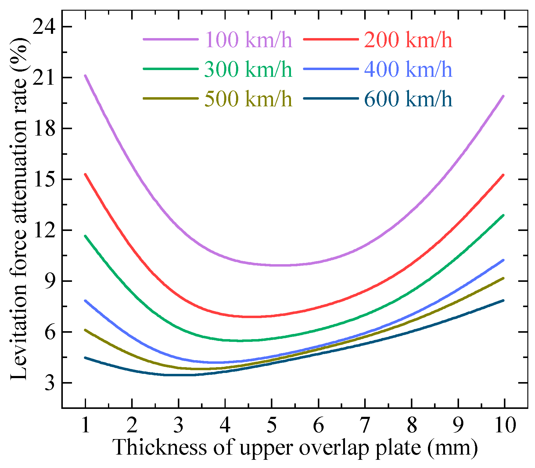
3.4. Analysis and Optimization of the Thickness of the Upper Overlap Plate
The analysis of Tu in the overlap joint requires particular attention to operational speed due to its influence on eddy current skin depth. Under controlled parameters (speed: 100–600 km/h, Tu: 1–10 mm), Figure 13 demonstrates the LAR variation with Tu across different speeds. For a given speed, LAR initially decreases and subsequently increases with Tu, defining a speed-specific optimal upper thickness (Topt) at the LAR minimum. Topt exhibits an inverse relationship with speed, decreasing by approximately 50% as speed increases from 100 km/h to 600 km/h.
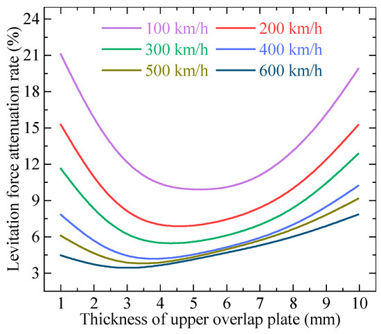
Figure 13.
Evolution of levitation force attenuation rate with thickness of upper overlap plate in overlap-joint under different speeds.
This behavior stems from the velocity-dependent skin effect: higher speeds reduce skin depth (δ), intensifying eddy current localization. When Tu < δ, incomplete eddy current formation occurs in the upper plate. Conversely, Tu > δ increases vertical eddy current separation between plates, degrading compensation efficacy. Thus, Topt corresponds to δ at each speed, ensuring eddy current continuity while minimizing LAR.
4. Dynamic Comparative Simulation
This section develops a vertical dynamic model of PMEDS. Through the application of distinct expansion joint excitations to the model, a comparative analysis of dynamic performance is conducted between the straight joint and the overlap joint.
4.1. Vertical Dynamic Analysis of the PMEDS Vehicle
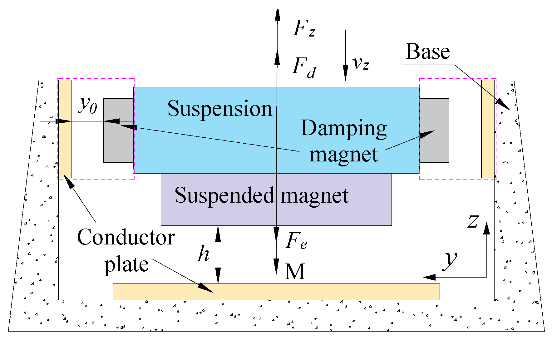
The vehicle incorporates damping magnets to address inherent weak damping characteristics, with structural configuration and force interactions detailed in Figure 14. Key system parameters include total mass (M):750 kg; levitation height (h); vertical vibration velocity (vz); levitation force (Fz); damping force (Fd); and expansion joint excitation force (Fe).
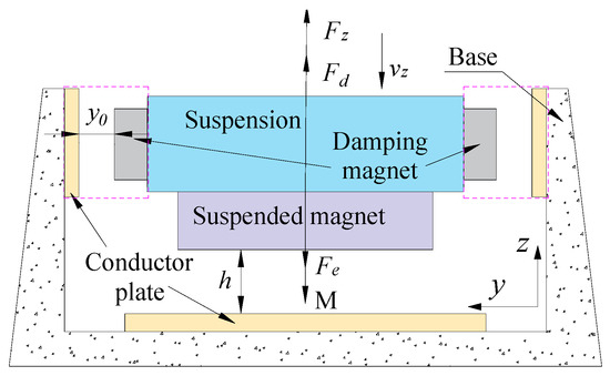
Figure 14.
Dynamic configuration and force of PMEDS.
Under the assumption of negligible flux variations induced by vertical vibrations, Fz exhibits an exclusive dependence on h, demonstrating an exponential decay relationship, as shown in Figure 15a. The fitting gives Fz, as in Equation (11):
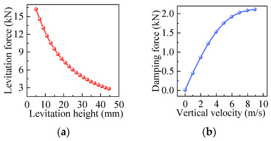
Figure 15.
Electromagnetic force characteristics in the dynamic model: (a) Levitation force; (b) Damping force.
For vertical damping dynamics, Fd correlates solely with vz. Figure 15b illustrates this cubic polynomial relationship, quantified as Equation (12):
The analysis incorporates expansion joint excitations with 25 m conductive plates. Following Section 3 optimizations, key parameters are configured as: straight joint (Le = 30 mm); overlap joint (Le = 30 mm, Lo = 90 mm, Tu = 4 mm). Electromagnetic simulations generate time-domain traversal curves for both joint types. Given plate length and rated velocity, expansion joint excitation occurs periodically at 0.36 s intervals.
4.2. Comparison of Dynamic Performance
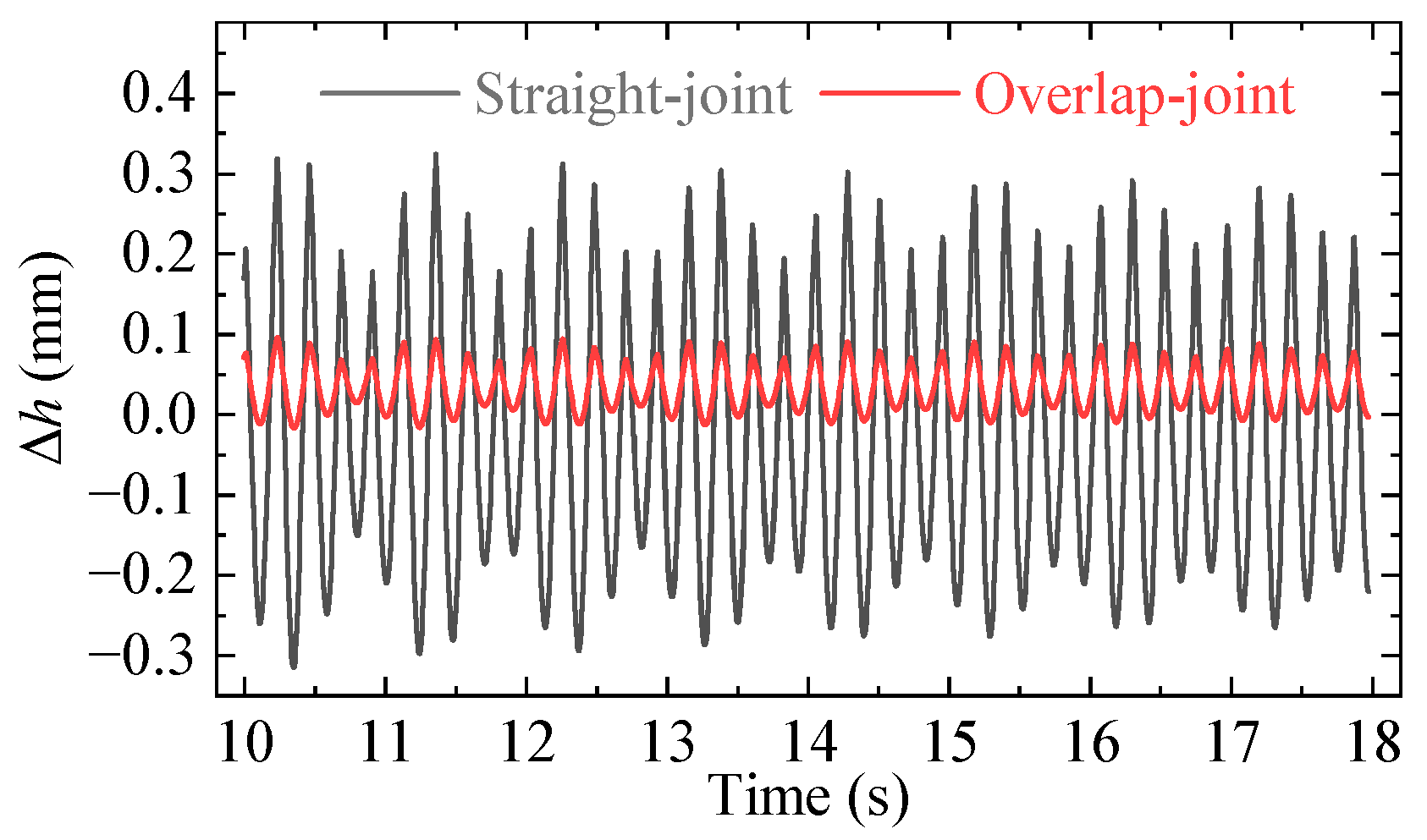
Following the application of expansion joint excitations to both straight joint and overlap joint configurations in the dynamic model, a comparative analysis of their dynamic performance was conducted under stabilized operating conditions.
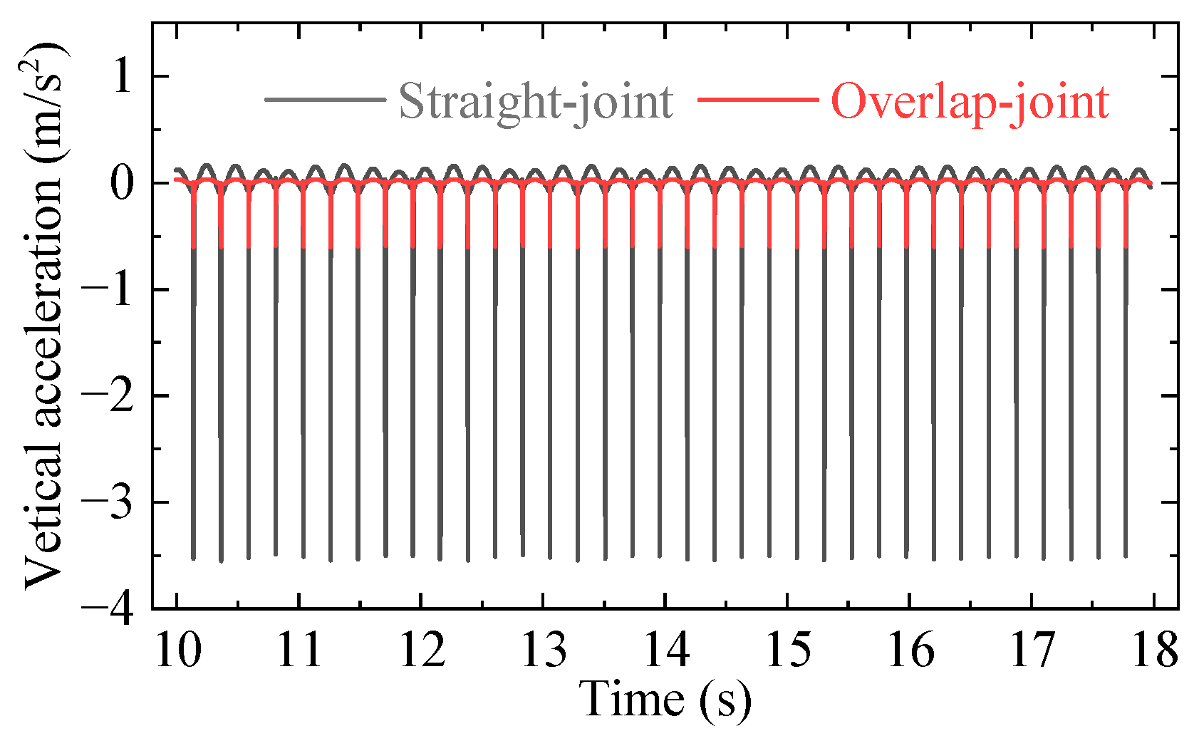
As shown in Figure 16, the Δh exhibits significantly reduced vibration amplitudes under overlap joint excitation (0.11 mm) compared to straight joint excitation (0.65 mm), corresponding to an 83% attenuation of vibration amplitude. Further analysis of vertical acceleration responses (Figure 17) demonstrates a substantial mitigation of peak acceleration values from 3.65 mm/s2 (straight joint) to 0.6 mm/s2 (overlap joint), achieving an 81% reduction.

Figure 16.
Variation in levitation height response to expansion joint excitations: straight joint vs. overlap joint.
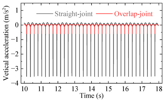
Figure 17.
Vertical acceleration characteristics under joint excitations: straight joint vs. overlap joint.
5. Magnetic Wheel Equivalence Experiment
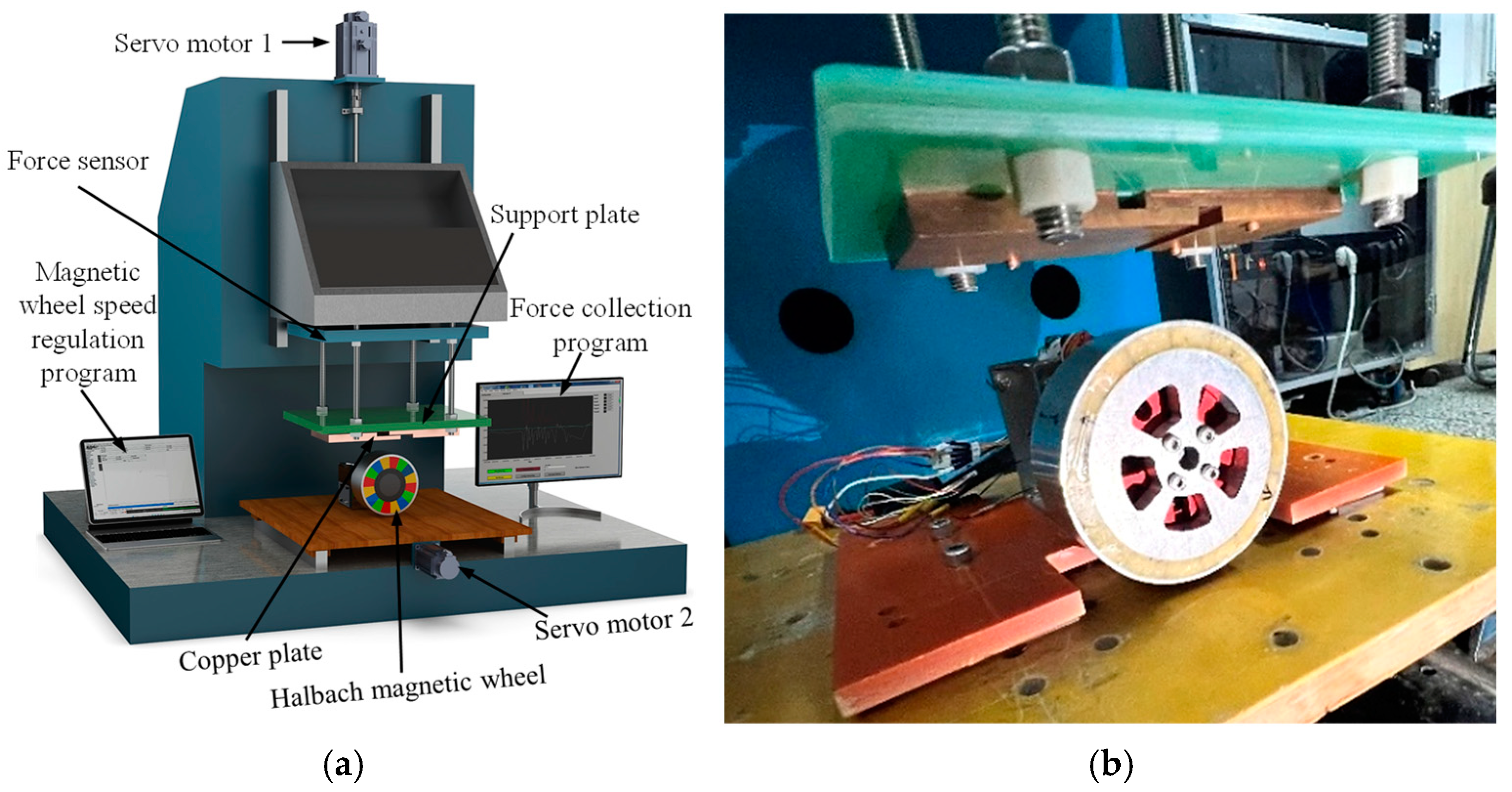
Building upon the established experimental configuration, a magnetic wheel equivalence test was conducted to validate the superiority of overlap joint configurations in PMEDS. The experimental platform for characterizing levitation force at expansion joints is illustrated in Figure 18.
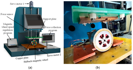
Figure 18.
Magnetic wheel equivalent experimental setup for expansion joints: (a) Overall assembly drawing; (b) Detailed image.
As illustrated in Figure 18, the experimental configuration employs a circumferential Halbach array of PMs mounted on a motor-driven rotating wheel, generating a continuous peripheral magnetic field [35]. This rotational Halbach array of PMs produces periodic magnetic field variations at fixed spatial coordinates, simulating the translation of linear Halbach array PMs.
The conductive plate above the magnetic wheel is rigidly mounted via the support plate. The outer circular holes on the insulating support plate are bolted to the upper force transducer, while the four central oblong slots are designed to accommodate different types of conductive plates. The conductive plates are bolted through their circular holes to the oblong slots on the support plate, enabling rapid replacement and allowing adjustment of the expansion joint length by sliding the bolts within the oblong slots. This configuration facilitates the simulation of various conductive plate arrangements under operational conditions.
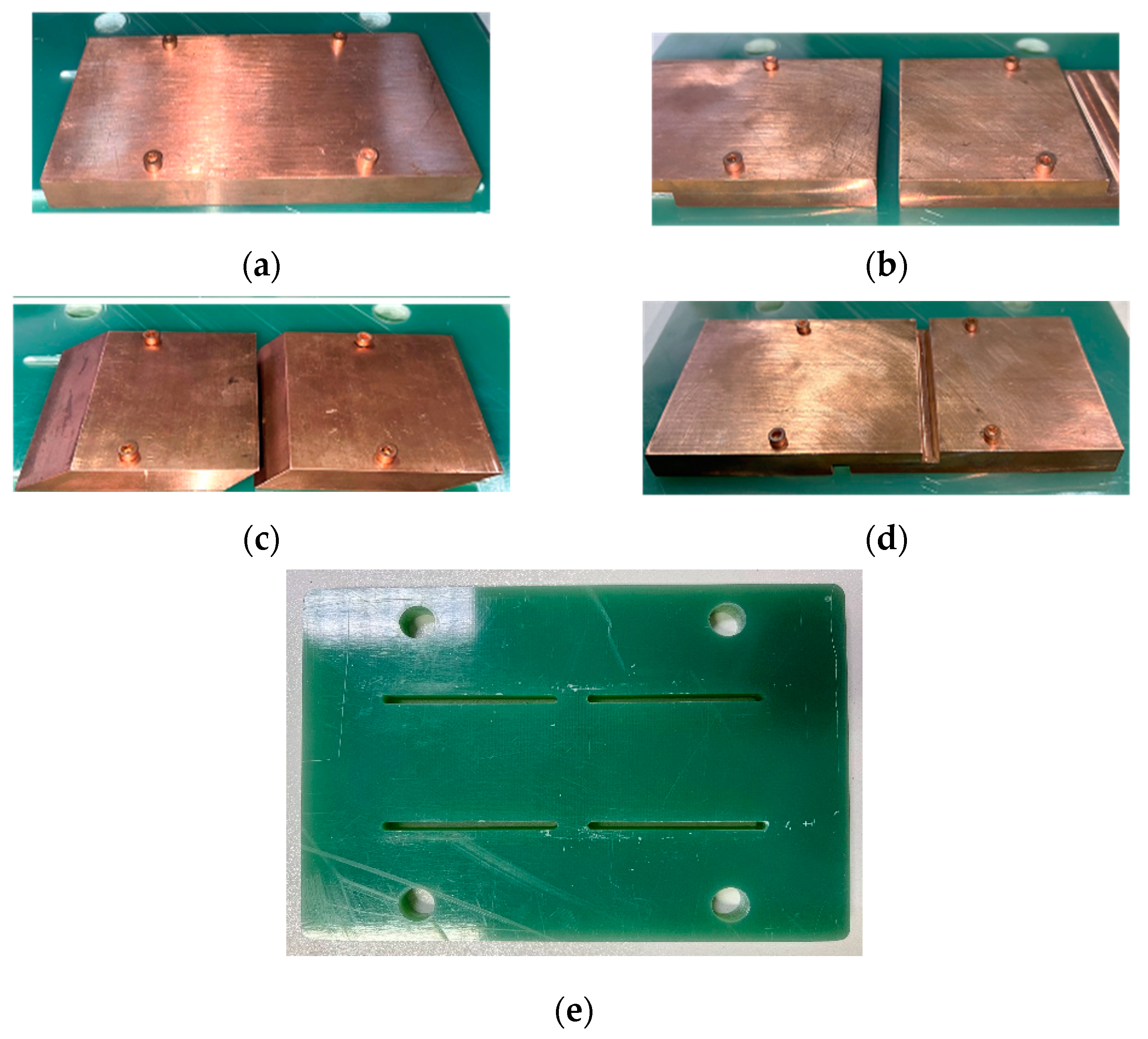
Furthermore, an angled seam conductive plate, as illustrated in Figure 19c, is engineered as a comparative test structure (hereinafter referred to as the angled joint). For the three expansion joint types, Le is adjustable through oblong slots integrated into the support plate. Figure 19 presents the assembly schematics of the four conductive plate configurations alongside the modular support system.

Figure 19.
Conductive plates of different expansion joints and support plate: (a) Complete conductive plate; (b) Straight joint; (c) Angled joint; (d) Overlap joint; (e) Support plate.
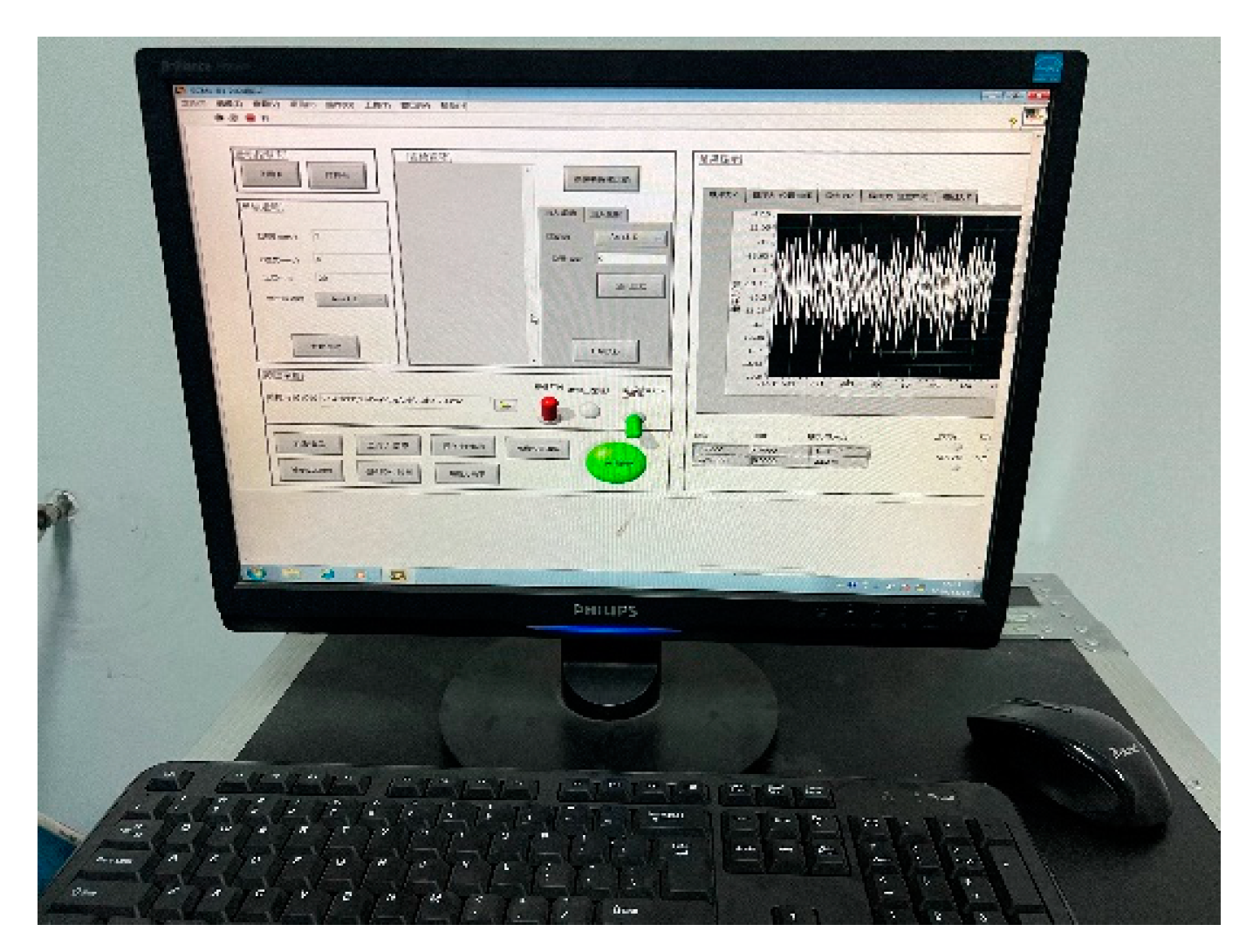
The support plate is connected to a precision force transducer (Omega85) coupled to a real-time data acquisition system, enabling the measurement of levitation forces. Configured with a Z-axis measurement range of 0–950 N, the transducer achieves 0.107 N resolution through 28-bit analog-to-digital conversion, sampled at 100 Hz to capture transient force dynamics. Figure 20 details the force acquisition interface, highlighting time-synchronized waveform visualization.
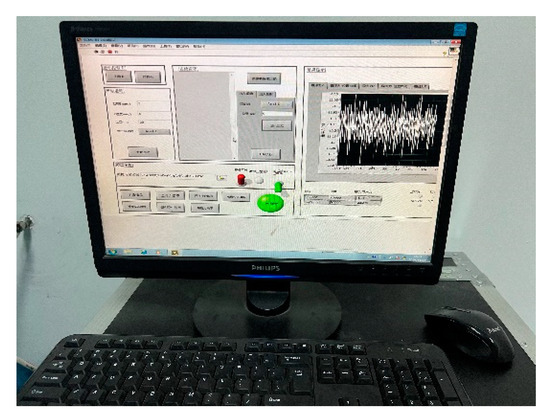
Figure 20.
Levitation force acquisition program interface.
The specifications of the experimental equipment are shown in Table 2.
Table 2.
Primary structure specifications of the test rig.
The experimental protocol involved precise alignment of component centers via servo-controlled positioning. A fixed air gap between the magnetic wheel periphery and the conductive plate surface was established using a servo motor. Following Le configuration (2–10 mm range, 1 mm increments) and transducer calibration, the rotational drive system was energized to generate levitation forces. Data acquisition commenced upon force stabilization, seeing steady-state force averages within ±0.3 N fluctuation bands.
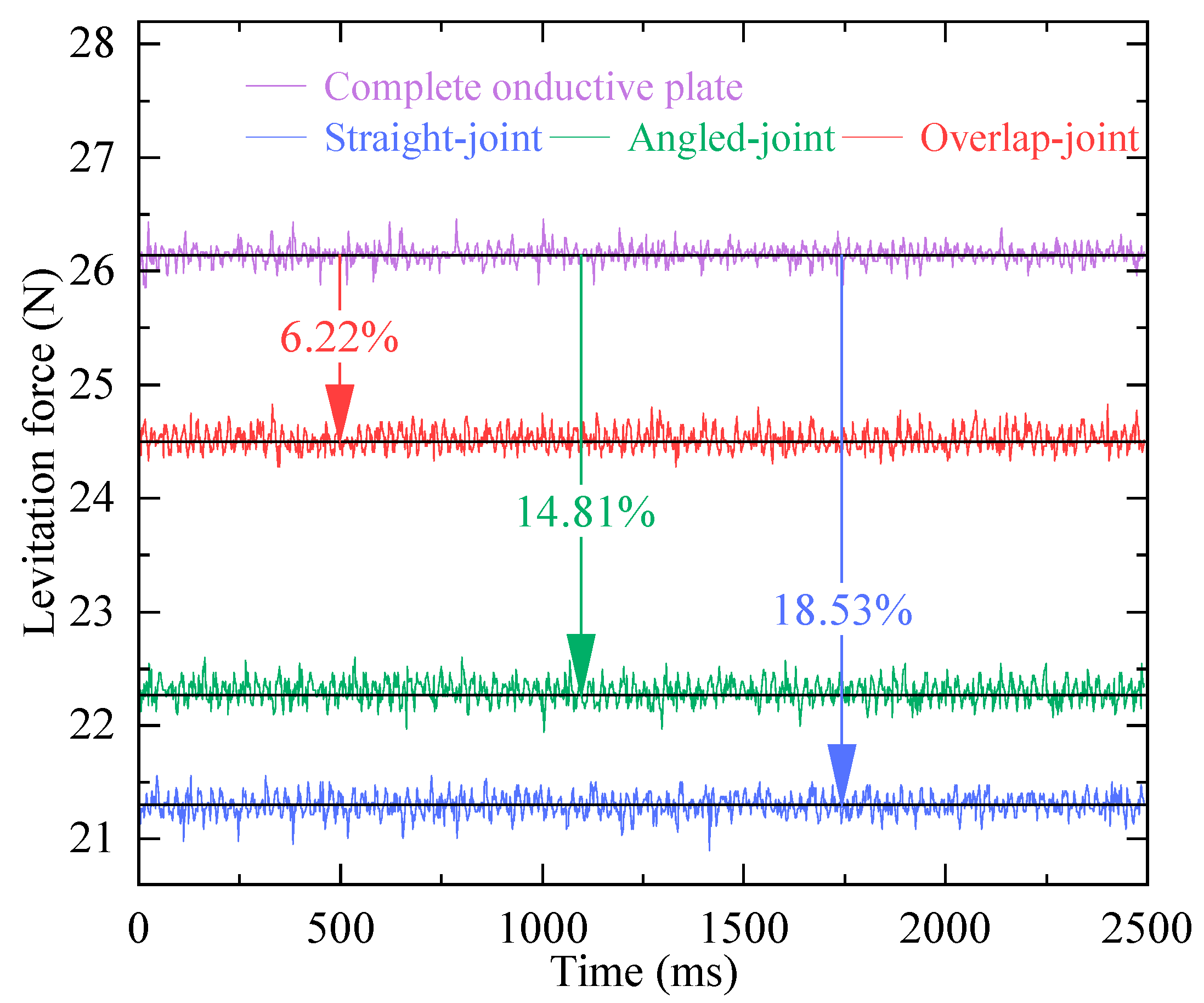
Figure 21 compares time-domain levitation force profiles for three expansion joint types (Le = 2 mm) against the complete conductive plate. A comparative analysis reveals levitation force reductions relative to the complete conductive plate baseline: (straight joint: 18.53% decrease; angled joint: 14.81% decrease; overlap joint: 6.22% decrease).
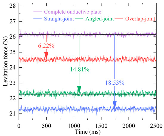
Figure 21.
Time-domain curves of experimental levitation force for different conductive plate structures.
This performance hierarchy aligns with eddy current continuity principles: straight joint exhibits maximum force attenuation due to abrupt current truncation at joint interfaces; angled joint demonstrates intermediate performance through gradual current transition; overlap joint achieves near-continuous current flow, minimizing force reduction.
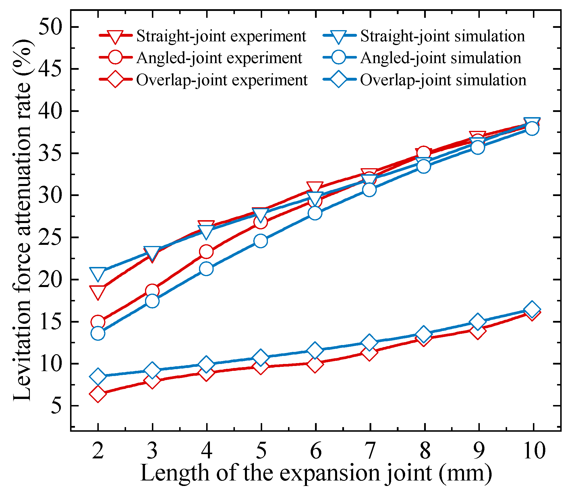
The average value during steady-state operation is defined as the levitation force under specified working conditions. Following the LAR definition methodology established in Section 3, the LAR for the magnetic wheel equivalent experiment was determined. An electromagnetic simulation model corresponding to the experimental setup was constructed, with parameters identical to the test conditions. Figure 22 illustrates the LAR variation curves for the three expansion joint configurations as Le increases.
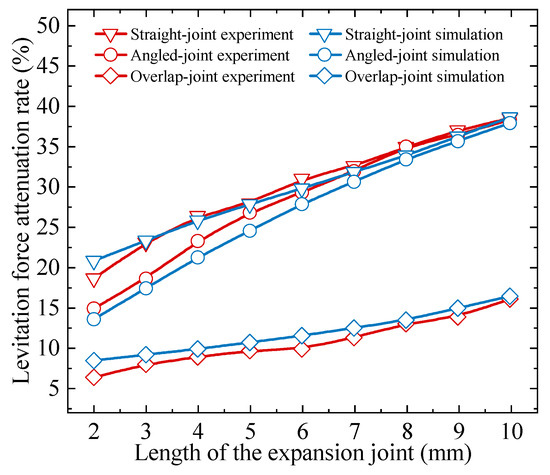
Figure 22.
Evolution of LAR with Le in the experiment and simulation for three expansion joints.
The overlap joint exhibits lower LAR values than both straight joint and angled seam across all tested Le ranges, with a significantly attenuated growth rate compared to the other configurations. Furthermore, the trends observed in finite element analysis closely align with experimental data, confirming that the magnetic wheel equivalent experiments accurately replicate the levitation force characteristics of the expansion joints discussed in Section 3. This consistency validates the electromagnetic properties of plate-type PMEDS expansion joints and demonstrates the superiority of the overlap joint compensation.
6. Conclusions
This study investigates the impact of expansion joints in conductive plates on the performance of the PMEDS vehicle, introducing an innovative overlap joint compensation structure. The effectiveness of this compensation scheme is validated through comprehensive simulations and experimental tests. Simulation results reveal that at Le = 10 mm, the LAR for the overlap joint decreases from 25% to 5% compared to the straight joint. Experimental data further confirm this improvement, showing a reduction in LAR from 18.53% to 6.22% at Le = 2 mm. The study also conducts parametric optimization of Le, Lo, and Tu within the overlap joint configuration, establishing optimal design criteria. Dynamic analysis demonstrates that the optimized overlap joint reduces levitation height vibration amplitude by 83% and peak vertical acceleration by 81% compared to the straight joint under expansion joint excitations. The overlap joint compensation structure holds significant potential for mitigating the adverse effects of expansion joints in PMEDS applications, thereby enhancing vehicle stability and ride comfort. These findings also provide a reference for improving guideway expansion joints in other long-distance magnetic levitation systems.
Author Contributions
Conceptualization, S.Z.; Funding acquisition, Z.D.; Project administration, Z.D.; Software, S.W.; Supervision, H.S.; Validation, S.W. and Z.L.; Writing—original draft, S.Z.; Writing—review and editing, H.S. All authors have read and agreed to the published version of the manuscript.
Funding
This work was supported by the Open Foundation of the State Key Laboratory of High-speed Maglev Transportation Technology (SKLM-SFCF-2023-008).
Institutional Review Board Statement
Not applicable.
Informed Consent Statement
Not applicable.
Data Availability Statement
The data reported in this manuscript is accessible based on reasonable requests to the corresponding author.
Conflicts of Interest
The authors declare no conflicts of interest.
References
- Lee, H.; Kim, K.; Lee, J. Review of maglev train technologies. IEEE Trans. Magn. 2006, 42, 1917–1925. [Google Scholar]
- Tandan; Kumar, G.; Sahu, G.; Sharma, R.; Bohidar, S. A review on development and analysis of maglev train. Int. J. Res. Advent Technol. 2023, 3, 14–17. [Google Scholar]
- Gysen, B.L.J.; Paulides, J.J.H.; Janssen, J.L.G.; Lomonova, E.A. Active Electromagnetic Suspension System for Improved Vehicle Dynamics. IEEE Trans. Veh. Technol. 2010, 59, 1156–1163. [Google Scholar] [CrossRef]
- Li, F.; Sun, Y.; Xu, J.; He, Z.; Lin, G. Control methods for levitation system of EMS-type maglev vehicles: An overview. Energies 2023, 16, 2995–3021. [Google Scholar] [CrossRef]
- Deng, Z.; Zhang, W.; Zheng, J.; Wang, B.; Ren, Y.; Zheng, X.; Zhang, J. A High-Temperature Superconducting Maglev-Evacuated Tube Transport (HTS Maglev-ETT) Test System. IEEE Trans. Appl. Supercond. 2017, 27, 3602008. [Google Scholar] [CrossRef]
- Bernstein, P.; Noudem, J. Superconducting magnetic levitation: Principle, materials, physics and models. Supercond. Sci. Technol. 2020, 33, 033001. [Google Scholar] [CrossRef]
- Deng, Z.; Zhang, W.; Wang, L.; Wang, Y.; Zhou, W.; Zhao, J.; Lu, K.; Guo, J.; Zhang, W.; Zhou, X.; et al. A High-Speed Running Test Platform for High-Temperature Superconducting Maglev. IEEE Trans. Appl. Supercond. 2022, 32, 3600905. [Google Scholar] [CrossRef]
- Tramacere, E.; Pakštys, M.; Galluzzi, R.; Amati, N.; Tonoli, A.; Lembke, T.A. Modeling and experimental validation of electrodynamic maglev systems. J. Sound Vib. 2024, 568, 117950. [Google Scholar] [CrossRef]
- He, G.; Long, Z.; Cheng, Y. The development and application of permanent-magnet EDS based on Halbach structure. In Proceedings of the 29th Chinese Control Conference, Beijing, China, 29–31 July 2010; pp. 5457–5462. [Google Scholar]
- Beauloye, L.; Dehez, B. Permanent Magnet Electrodynamic Suspensions Applied to MAGLeV Transportation Systems: A Review. IEEE Trans. Transp. Electrif. 2023, 9, 748–758. [Google Scholar] [CrossRef]
- Rezaei, H.; Vaez-Zadeh, S. Modelling and analysis of permanent magnet electrodynamic suspension systems. Prog. Electromagn. Res. M 2014, 36, 77–84. [Google Scholar] [CrossRef]
- Fang, J.; Montgomery, D.B.; Roderick, L. A Novel MagPipe Pipeline Transportation System Using Linear Motor Drives. Proc. IEEE 2009, 97, 1848–1855. [Google Scholar] [CrossRef]
- Post, R.F.; Ryutov, D.D. The Inductrack: A simpler approach to magnetic levitation. IEEE Trans. Appl. Supercond. 2000, 10, 901–904. [Google Scholar] [CrossRef]
- Nøland, J.K. Prospects and Challenges of the Hyperloop Transportation System: A Systematic Technology Review. IEEE Access 2021, 9, 28439–28458. [Google Scholar] [CrossRef]
- Abdelrahman, A.S.; Sayeed, J.; Youssef, M.Z. Hyperloop Transportation System: Analysis, Design, Control, and Implementation. IEEE Trans. Ind. Electron. 2018, 65, 7427–7436. [Google Scholar] [CrossRef]
- Sutar, A.V.; Raut, S.V.; Kulkarni, R.K. Hyperloop System Implementation using Magnetic Levitation Principle. In Proceedings of the 2020 4th International Conference on Intelligent Computing and Control Systems (ICICCS), Madurai, India, 13–15 May 2020; pp. 979–983. [Google Scholar]
- Rote, D.M.; Cai, Y. Review of dynamic stability of repulsive-force maglev suspension systems. IEEE Trans. Magn. 2002, 38, 1383–1390. [Google Scholar] [CrossRef]
- Circosta, S.; Galluzzi, R.; Amati, N.; Tonoli, A.; Bonfitto, A.; Lembke, T.A.; Kertész, M. Passive multi-degree-of-freedom stabilization of ultra-high-speed maglev vehicles. J. Vib. Acoust. 2021, 143, 061003. [Google Scholar] [CrossRef]
- Ko, W.; Ham, C. A Novel Approach to Analyze the Transient Dynamics of an Electrodynamics Suspension Maglev. IEEE Trans. Magn. 2007, 43, 2603–2605. [Google Scholar] [CrossRef]
- Deng, Z.; Shi, H.; Ke, Z.; Liu, J.; Li, Z.; Zhang, B.; Jiang, Z.; Zhou, J.; Liu, Y. Permanent Magnet Electrodynamic Suspension System Integrated with a Car: Design, Implementation, and Test. IEEE Trans. Transp. Electrif. 2024, 10, 1101–1115. [Google Scholar] [CrossRef]
- Wu, C.; Li, G.; Wang, D.; Xu, J. Dynamic characterization of permanent magnet electrodynamic suspension system with a novel passive damping magnet scheme. J. Sound Vib. 2025, 599, 118849. [Google Scholar] [CrossRef]
- Hu, Y.; Zeng, J.; Long, Z. Analysis of Dynamic Characteristics of Electrodynamic Suspension Train Based on Halbach Permanent Magnet Array. In Proceedings of the 2019 Chinese Automation Congress (CAC), Hangzhou, China, 22–24 November 2019; pp. 3754–3758. [Google Scholar]
- Shi, H.; Yang, W.; Fu, S.; Liu, H.; Yang, J.; Li, K.; Deng, Z. Characteristics Analysis and Dynamic Test of Air-Cored Permanent Magnet Linear Synchronous Motor for Null-Flux PMEDS Vehicle. IEEE Trans. Instrum. Meas. 2024, 73, 3524115. [Google Scholar] [CrossRef]
- Galluzzi, R.; Circosta, S.; Amati, N.; Tonoli, A.; Bonfitto, A.; Lembke, T.A.; Kertész, M. A multi-domain approach to the stabilization of electrodynamic levitation systems. J. Vib. Acoust. 2020, 42, 061004. [Google Scholar] [CrossRef]
- Tan, S.; Lin, C.; Mei, Q. Study on the Operational Status of Rail Expansion Joints in Ballasted Track of High-Speed Railways. J. Railw. Sci. Eng. 2021, 18, 837–843. [Google Scholar]
- Rossing, T.D.; Korte, R.; Hull, J.R. Effect of guideway discontinuities on magnetic levitation and drag forces. J. Appl. Phys. 1991, 70, 6507–6509. [Google Scholar] [CrossRef]
- Choi, J.S.; Yoo, J. Design of a Halbach Magnet Array Based on Optimization Techniques. IEEE Trans. Magn. 2008, 44, 2361–2366. [Google Scholar] [CrossRef]
- Jiao, S.; Liu, X.; Zeng, Z. Intensive Study of Skin Effect in Eddy Current Testing with Pancake Coil. IEEE Trans. Magn. 2017, 53, 6201608. [Google Scholar] [CrossRef]
- Zhou, R.; Li, G.; Wang, Q.; He, J. Torque Calculation of Permanent-Magnet Spherical Motor Based on Permanent-Magnet Surface Current and Lorentz Force. IEEE Trans. Magn. 2020, 56, 8200209. [Google Scholar] [CrossRef]
- Cao, T.; Shi, H.; Liu, J.; Wu, X.; Deng, Z. Investigation of Electromagnetic Force Characteristics of Permanent Magnet Electrodynamic Suspension under Multi-Operation Conditions. Trans. China Electrotech. Soc. 2024, 39, 5262–5277. [Google Scholar]
- Ghosh, M.K.; Gao, Y.; Dozono, H.; Muramatsu, K.; Guan, W.; Yuan, J.; Tian, C.; Chen, B. Proposal of Maxwell Stress Tensor for Local Force Calculation in Magnetic Body. IEEE Trans. Magn. 2018, 54, 7206204. [Google Scholar] [CrossRef]
- Huang, C.; Kou, B.; Zhao, X.; Niu, X. Improved Analytical Model for the Magnetic Drag of a Dual-Conductor Plate Parallel Electric Suspension and Guiding Mechanism. IEEE Trans. Ind. Electron. 2023, 70, 11994–12002. [Google Scholar] [CrossRef]
- Pechenkov, A.N.; Scherbinin, V.E. Eddy currents and conducting and magnetizable spherical inclusions fields in a nonmagnetic medium. Russ. J. Nondestruct. Test. 2016, 52, 226–234. [Google Scholar] [CrossRef]
- Valagiannopoulos, C. Single-Series Solution to the Radiation of Loop Antenna in the Presence of a Conducting Sphere. Prog. Electromagn. Res. 2007, 71, 277–294. [Google Scholar] [CrossRef]
- Yuan, Y.; Deng, Z.; Zhang, S.; Ke, Z.; Shi, H.; Wang, Z.; Zhang, J.; Zheng, J. Working Principle and Primary Electromagnetic Characteristics of a Permanent Magnet Electrodynamic Wheel for Maglev Car Application. IEEE Trans. Appl. Supercond. 2021, 31, 3603905. [Google Scholar] [CrossRef]


Disclaimer/Publisher’s Note: The statements, opinions and data contained in all publications are solely those of the individual author(s) and contributor(s) and not of MDPI and/or the editor(s). MDPI and/or the editor(s) disclaim responsibility for any injury to people or property resulting from any ideas, methods, instructions or products referred to in the content. |
© 2025 by the authors. Licensee MDPI, Basel, Switzerland. This article is an open access article distributed under the terms and conditions of the Creative Commons Attribution (CC BY) license (https://creativecommons.org/licenses/by/4.0/).