Novel Additive Manufacturing Pneumatic Actuators and Mechanisms for Food Handling Grippers


Abstract
:
1. Introduction
2. Grippers for Handling Food: Design Requirements
3. Additive Manufacturing Pneumatic Actuators
3.1. Classification of AM Actuators Based on Kind of Motion
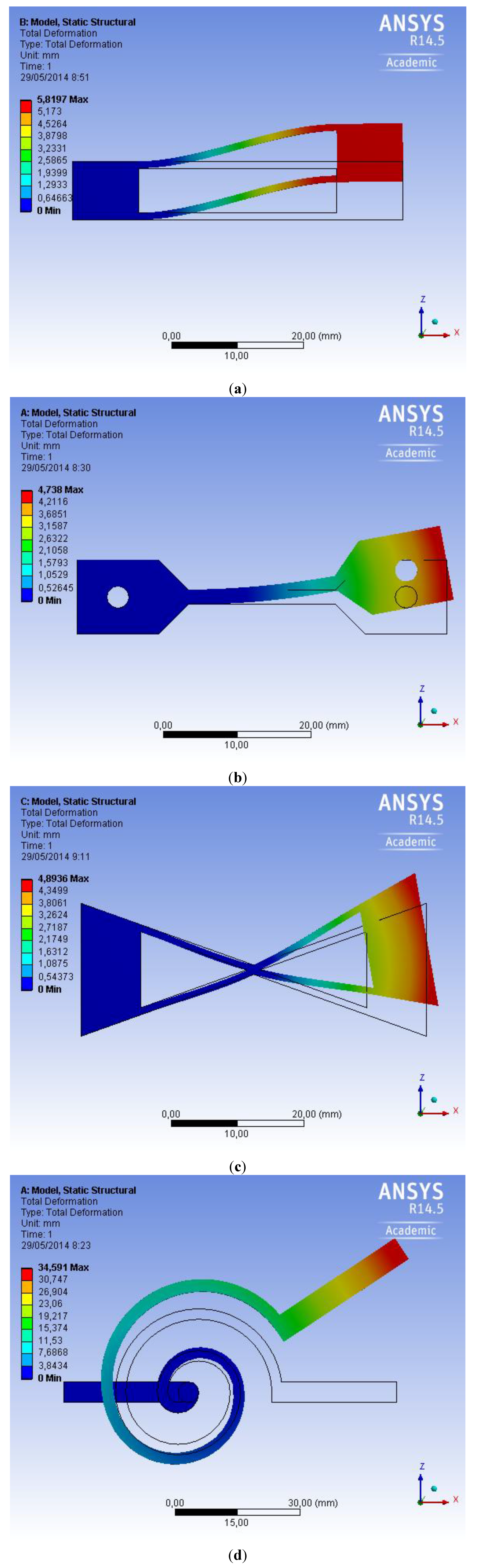
3.1.1. AM Actuator with Linear Motion

3.1.2. AM Actuator with Rotation and Linear Motion


3.1.3. AM Actuator with Double Effect

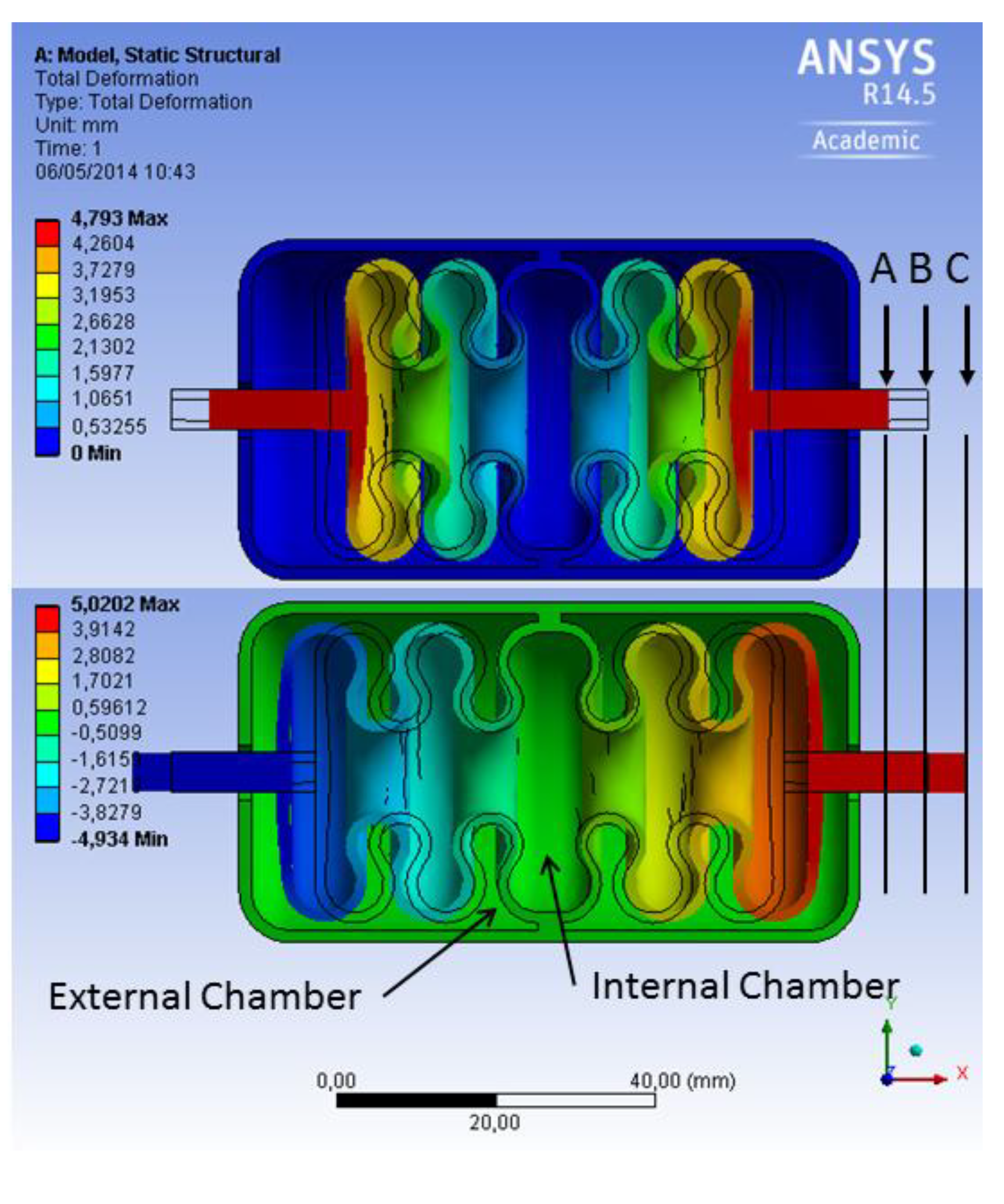
| Internal Chamber Pressure | External Chamber Pressure | Displacement |
|---|---|---|
| Atmospheric | 0.4 MPa | A |
| Atmospheric | Atmospheric | B |
| 0.4 MPa | Atmospheric | C |

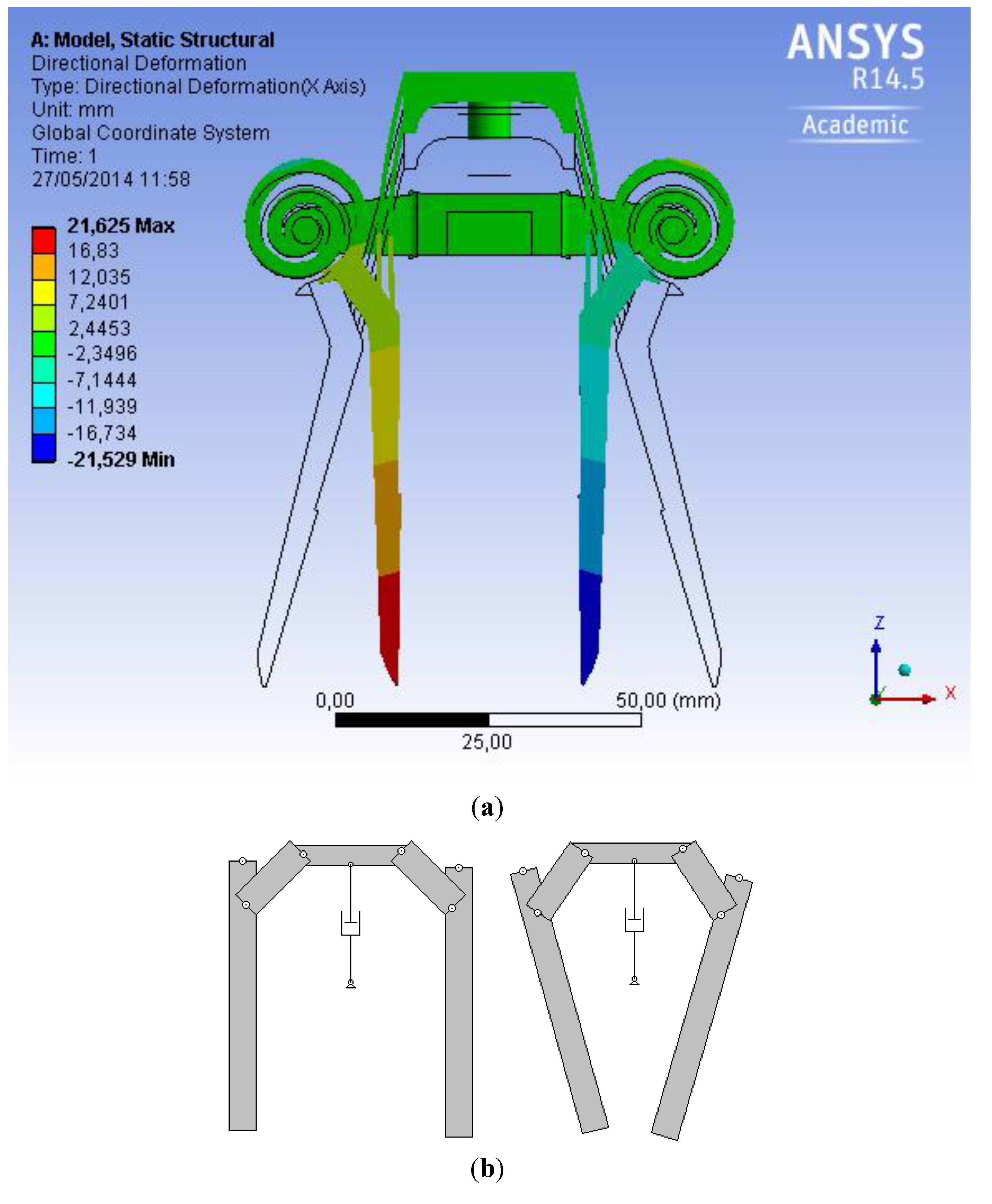
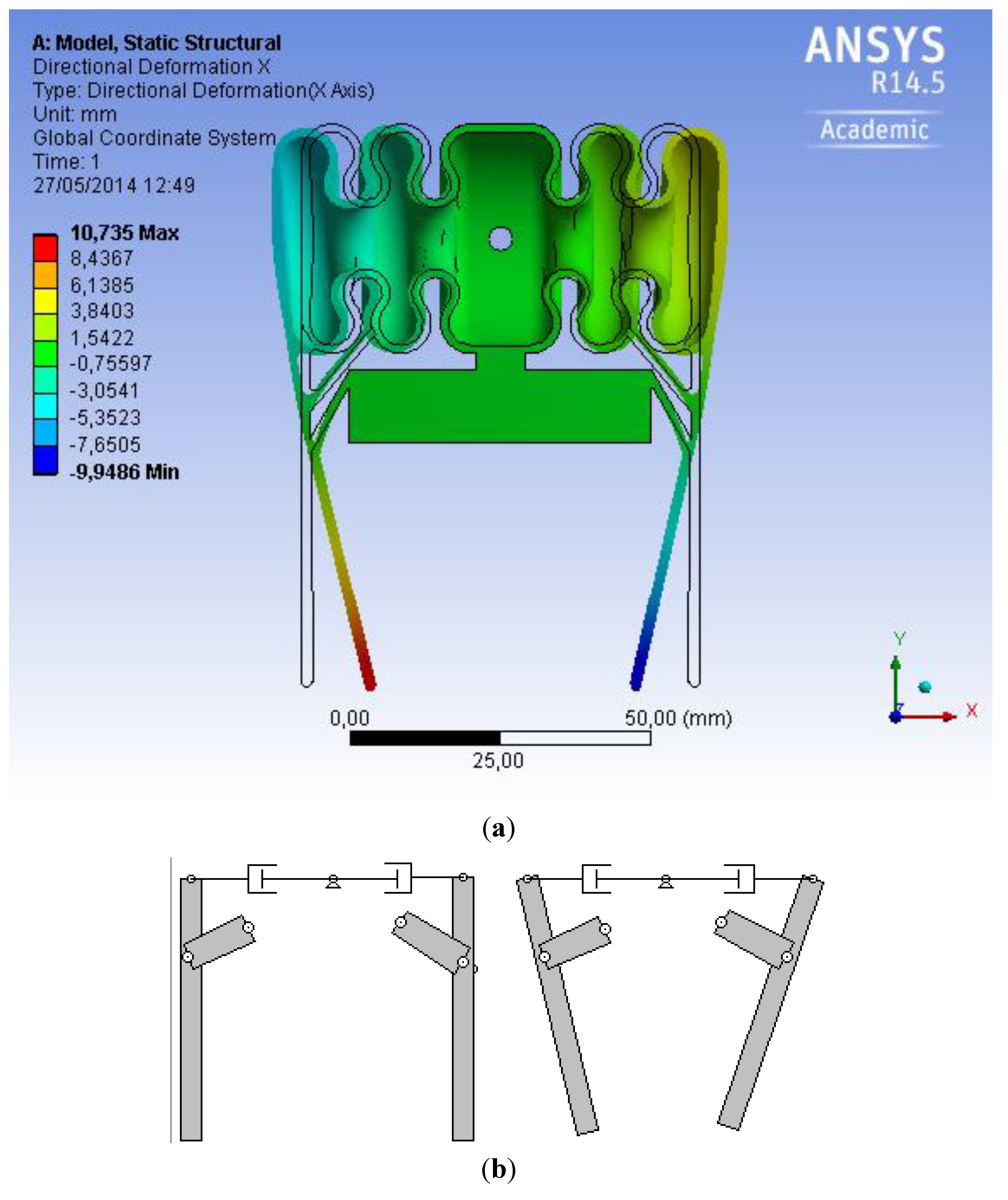
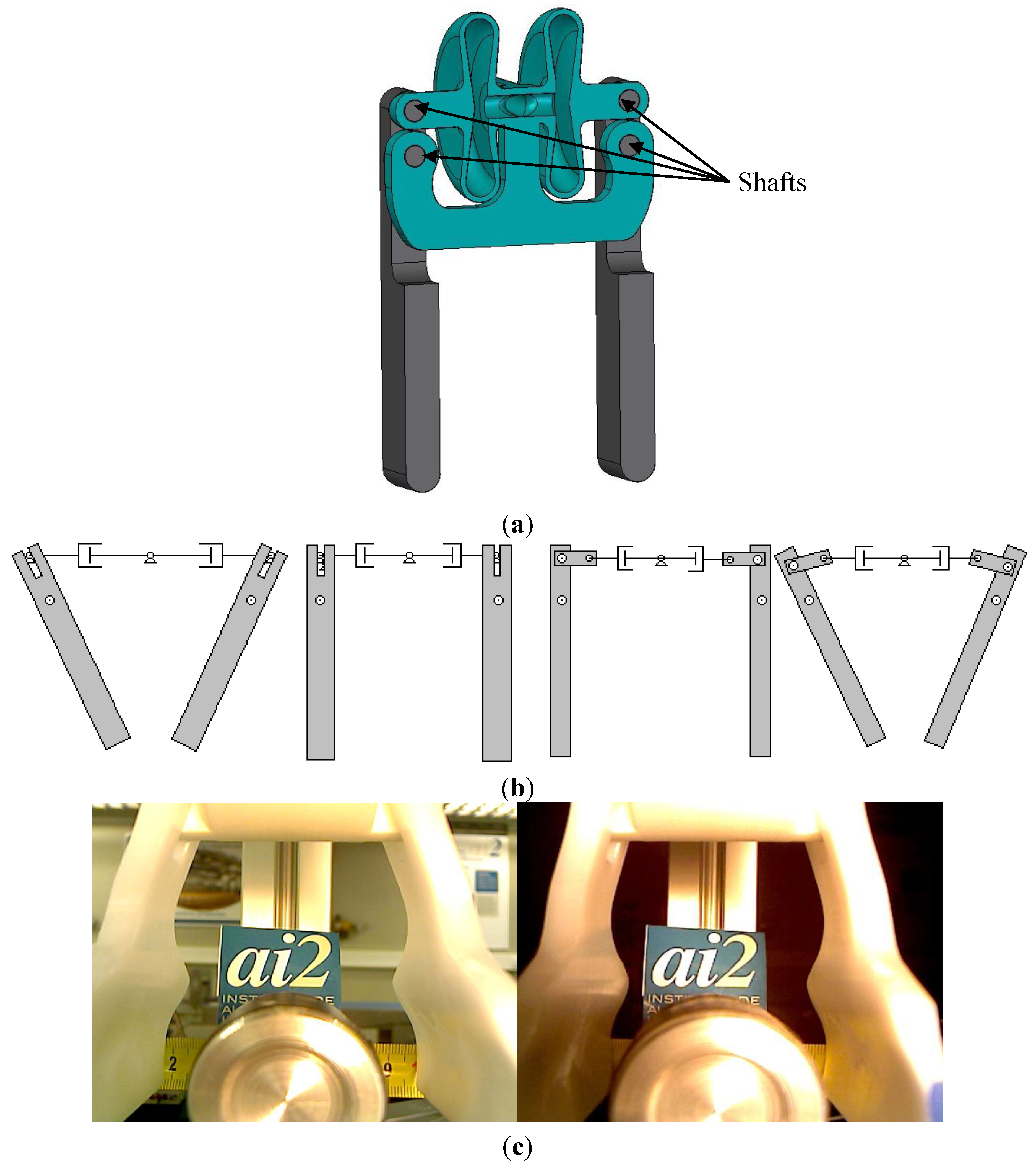
3.2. AM for Compliant Mechanisms

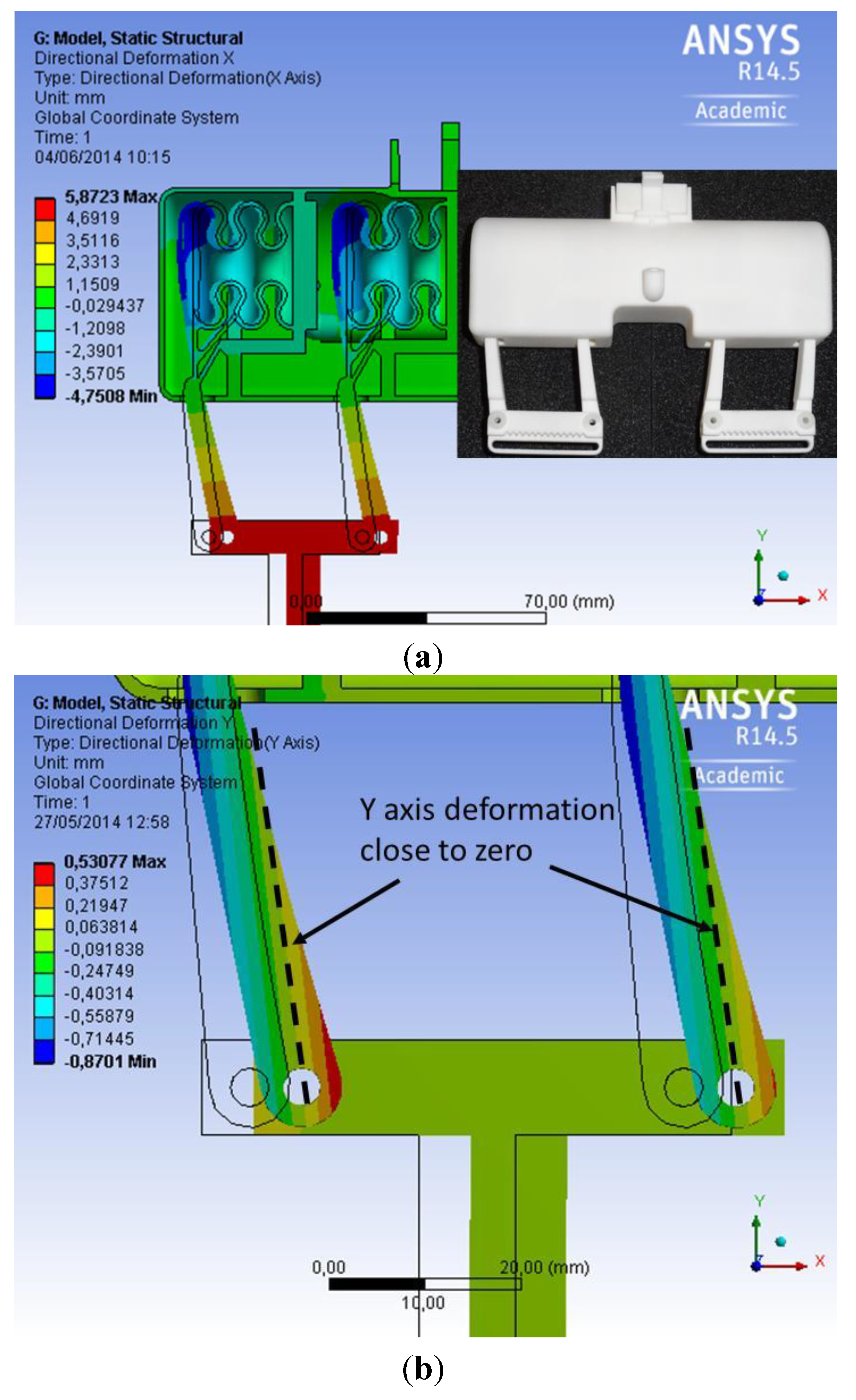
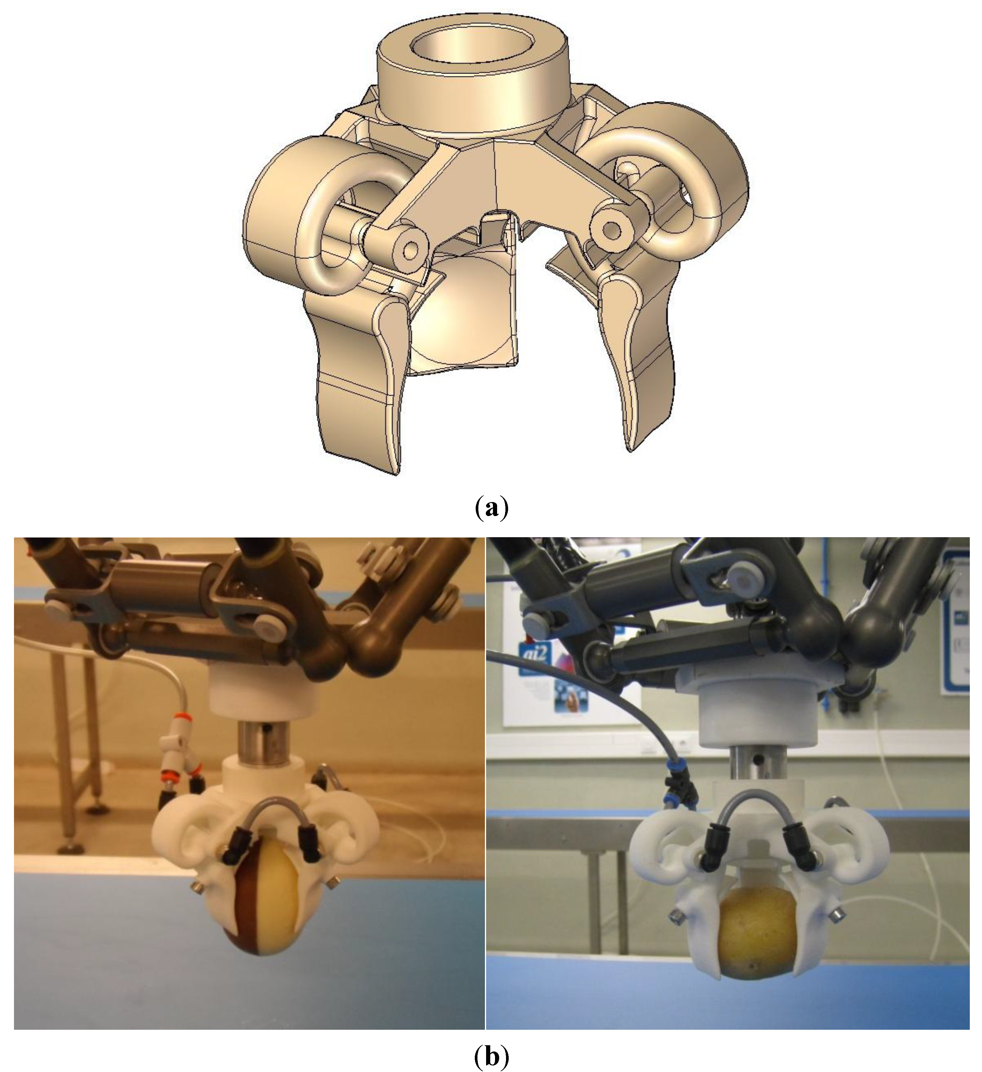
3.3. AM for the Design of Pneumatic Robot Grippers


4. Results and Discussion
5. Conclusions
Acknowledgments
Author Contributions
Conflicts of Interest
References
- Wilson, M. Developments in Robot Applications for Food Manufacturing. Ind. Robot 2010, 37, 498–502. [Google Scholar] [CrossRef]
- Todd, E.C.; Michaels, B.S.; Smith, D.; Greig, J.D.; Bartleson, C.A. Outbreaks Where Food Workers have been Implicated in the Spread of Foodborne Disease. Part 9. Washing and Drying of Hands to Reduce Microbial Contamination. J. Food Prot. 2010, 73, 1937–1955. [Google Scholar]
- Masey, R.J.M. Guidelines for the Design of Low-Cost Robots for the Food Industry. Ind. Robot 2010, 37, 509–517. [Google Scholar]
- Holmes, J.F. Guidelines for Designing Washdown Robots for Meat Packaging Applications. Trends Food Sci. Technol. 2010, 21, 158–163. [Google Scholar] [CrossRef]
- Chua, P.; Ilschner, T.; Caldwell, D. Robotic Manipulation of Food products—A Review. Ind. Robot 2003, 30, 345–354. [Google Scholar] [CrossRef]
- Pettersson, A.; Ohlsson, T.; Davis, S.; Gray, J.O.; Dodd, T.J. A Hygienically Designed Force Gripper for Flexible Handling of Variable and Easily Damaged Natural Food Products. Innov. Food Sci. Emerg. Technol. 2011, 12, 344–351. [Google Scholar] [CrossRef]
- Blanes, C.; Mellado, M.; Ortiz, C.; Valera, A. Technologies for Robot Grippers in Pick and Place Operations for Fresh Fruits and Vegetables. Span. J. Agric. Res. 2011, 9, 1130–1141. [Google Scholar] [CrossRef]
- Laliberte, T.; Gosselin, C.M. Simulation and Design of Underactuated Mechanical Hands. Mech. Mach. Theory 1998, 33, 39–57. [Google Scholar] [CrossRef]
- Laliberte, T.; Birglen, L.; Gosselin, C. Underactuation in Robotic Grasping Hands. Mach. Intell. Robot. Control 2002, 4, 1–11. [Google Scholar]
- Meijneke, C.; Kragten, G.; Wisse, M. Design and Performance Assessment of an Underactuated Hand for Industrial Applications. Mech. Sci. 2011, 2, 9–15. [Google Scholar] [CrossRef]
- Van der Linde, R.Q. Available online: http://food.lacquey.nl/ (accessed on 30 June 2014).
- Available online: http://robotiq.com/en/ (accessed on 30 June 2014).
- Choi, H.; Koē, M. Design and Feasibility Tests of a Flexible Gripper Based on Inflatable Rubber Pockets. Int. J. Mach. Tools Manuf. 2006, 46, 1350–1361. [Google Scholar] [CrossRef]
- Available online: http://www.adept.com/products/grippers (accessed on 30 June 2014).
- Brown, E.; Rodenberg, N.; Amend, J.; Mozeika, A.; Steltz, E.; Zakin, M.R.; Lipson, H.; Jaeger, H.M. From the Cover: Universal Robotic Gripper Based on the Jamming of Granular Material. Proc. Natl. Acad. Sci. USA 2010, 107, 18809–18814. [Google Scholar]
- Pettersson, A.; Davis, S.; Gray, J.; Dodd, T.; Ohlsson, T. Design of a Magnetorheological Robot Gripper for Handling of Delicate Food Products with Varying Shapes. J. Food Eng. 2010, 98, 332–338. [Google Scholar] [CrossRef]
- Zhong, Z.; Yeong, C. Development of a Gripper using SMA Wire. Sens. Actuators A Phys. 2006, 126, 375–381. [Google Scholar] [CrossRef]
- Maruyama, R.; Watanabe, T.; Uchida, M. Delicate Grasping by Robotic Gripper with Incompressible Fluid-Based Deformable Fingertips. In Proceedings of the IEEE/RSJ International Conference on Intelligent Robots and Systems (IROS), Tokyo, Japan, 3–8 November 2013; pp. 5469–5474.
- Van Ham, R.; Sugar, T.G.; Vanderborght, B.; Hollander, K.W.; Lefeber, D. Compliant Actuator Designs Review of Actuators with Passive Adjustable Compliance/Controllable Stiffness for Robotic Applications. Robot. Autom. Mag. 2009, 16, 81–94. [Google Scholar] [CrossRef]
- Vanderborght, B.; Albu-Schaeffer, A.; Bicchi, A.; Burdet, E.; Caldwell, D.G.; Carloni, R.; Catalano, M.; Eiberger, O.; Friedl, W.; Ganesh, G.; et al. Variable Impedance Actuators: A Review. Robot. Auton. Syst. 2013, 61, 1601–1614. [Google Scholar] [CrossRef]
- Zheng, H.; Shen, X. Double-Acting Sleeve Muscle Actuator for Bio-Robotic Systems. Actuators 2013, 2, 129–144. [Google Scholar] [CrossRef]
- Kim, S.; Laschi, C.; Trimmer, B. Soft Robotics: A Bioinspired Evolution in Robotics. Trends Biotechnol. 2013, 31, 287–294. [Google Scholar] [CrossRef]
- Deimel, R.; Brock, O. A Compliant Hand Based on a Novel Pneumatic Actuator. In Proceedings of the IEEE International Conference on Robotics and Automation (ICRA), Karlsruhe, Germany, 6–10 May 2013; pp. 2039–2045.
- Lipson, H. Challenges and Opportunities for Design, Simulation, and Fabrication of Soft Robots. Soft Robot. 2013, 1, 21–27. [Google Scholar] [CrossRef]
- Mosadegh, B.; Polygerinos, P.; Keplinger, C.; Wennstedt, S.; Shepherd, R.F.; Gupta, U.; Shim, J.; Bertoldi, K.; Walsh, C.J.; Whitesides, G.M. Pneumatic Networks for Soft Robotics that Actuate Rapidly. Adv. Funct. Mater. 2014, 24, 2163–2170. [Google Scholar] [CrossRef]
- Grzesiak, A.; Becker, R.; Verl, A. The Bionic Handling Assistant: A Success Story of Additive Manufacturing. Assem. Autom. 2011, 31, 329–333. [Google Scholar] [CrossRef]
© 2014 by the authors; licensee MDPI, Basel, Switzerland. This article is an open access article distributed under the terms and conditions of the Creative Commons Attribution license (http://creativecommons.org/licenses/by/3.0/).
Share and Cite
Blanes, C.; Mellado, M.; Beltran, P. Novel Additive Manufacturing Pneumatic Actuators and Mechanisms for Food Handling Grippers. Actuators 2014, 3, 205-225. https://doi.org/10.3390/act3030205
Blanes C, Mellado M, Beltran P. Novel Additive Manufacturing Pneumatic Actuators and Mechanisms for Food Handling Grippers. Actuators. 2014; 3(3):205-225. https://doi.org/10.3390/act3030205
Chicago/Turabian StyleBlanes, Carlos, Martín Mellado, and Pablo Beltran. 2014. "Novel Additive Manufacturing Pneumatic Actuators and Mechanisms for Food Handling Grippers" Actuators 3, no. 3: 205-225. https://doi.org/10.3390/act3030205
APA StyleBlanes, C., Mellado, M., & Beltran, P. (2014). Novel Additive Manufacturing Pneumatic Actuators and Mechanisms for Food Handling Grippers. Actuators, 3(3), 205-225. https://doi.org/10.3390/act3030205