Article

Electrical Performance of a Piezo-inductive Device for Energy Harvesting with Low-Frequency Vibrations

by
Carlos Alberto Vargas
1 and
Hector Andres Tinoco
1,2,3,*
1
Experimental and Computational Mechanics Laboratory, Universidad Autónoma de Manizales, Antigua Estación del Ferrocarril, Edificio Fundadores C.P. 170001, Manizales, Colombia
2
Institute of Physics of Materials, Science Academy of Czech Republic, Žižkova 22, 616 62 Brno, Czech Republic
3
Central European Institute of Technology (CEITEC)/Brno University of Technology, Technická 3058/10, 61600 Brno, Czech Republic
*
Author to whom correspondence should be addressed.
Actuators 2019, 8(3), 55; https://doi.org/10.3390/act8030055
Submission received: 11 June 2019 / Revised: 7 July 2019 / Accepted: 12 July 2019 / Published: 16 July 2019

Abstract

:
This study presents the experimental evaluation of a piezo-inductive mechanical system for applications of energy harvesting with low-frequency vibrations. The piezo-inductive vibration energy harvester (PI-VEH) device is composed of a voice coil motor (VCM) extracted from a hard disk drive. The proposed design allows the integration of different element types as beams and masses. The dynamic excitations in the system produce a pendular motion carried out by a hybrid arm (rigid-flexible) that generates energy with the rotations (with a coil) and the beam strains (with a piezoelectric material). The electrical assessment was performed through different working modes classified as inductive, inductive with magnetic instabilities, and piezo-inductive. The instabilities in the harvester refer to external forces induced by two magnets that repel each other. The first two inductive configurations were designed as a function of three parameters (length, mass, instability angle) to debug these using the maximum output voltage. The selected experiments were conducted in a piezo-inductive configuration. The results showed two effects on the output voltage—the first one is related to a system without resonances (higher broadband), and the second effect is associated with a multi-resonant system. As a final conclusion, it is pointed out that the electrical performance can be improved with the magnetic instabilities since these considerably amplified the output voltages.

1. Introduction

The development of new technologies has allowed electronic devices to interact remotely through integrated systems and sensors in different engineering applications [1]. The measurement of physical variables through the internet of things (IoT) is an application that has been growing in the technological ecosystem. However, the sensor systems depend on the energy supply to transmit, to store, and to compute the collected information [2]. The continuous operation of these systems could be guaranteed from the energy provided by the environment, which is available unlimitedly in nature [3]. Currently, some engineering fields have shown a potential application of the energy harvesting systems in process control, bio-monitoring, mobile communications, structural monitoring, etc. [4]. Furthermore, mobile systems require permanent energy that is supplied by the batteries in most cases, especially those located in remote areas. This last aspect becomes a limitation when having to perform a complex task without replacing the batteries, and this results in a high energy dependence in many applications [5]. For example, [6] show that the energy harvesting systems can feed sensor networks, since the replacement of the batteries can be very impractical due to its remote locations. For this case, the use of non-limited energy sources becomes relevant if energy harvesting technologies can capture, store, and supply the energy permanently to these sensor networks [7].
Different alternatives have been proposed to use the renewable energy sources through the energy scavenging, which is defined as the process by which the energy is transformed and provided into small quantities [8]. Diverse energy sources are used for this purpose, among which are solar, wind, electromagnetic radiation, thermal, and mechanical vibrations [9], and a combination of different transduction mechanisms can be integrated in order to capture the energy from these energy sources such as magnetostrictive, piezoelectric, electromagnetic, and electrostatic. These systems are called hybrid energy harvesters (HEH), as mentioned by [10]. Vibratory energy sources have shown promissory applications in devices that demand low power consumption [11]. Since the electrical power is obtained with resonant systems that can improve its electrical performance from the design focused on the excitation frequencies [12,13]. In this context, the energy generated by mechanical vibrations could be provided from the bridges, winds, river and sea waves, human body motions, etc. For the mentioned energy sources, [14] considers high frequencies to be above 50 Hz and low frequencies below that threshold.
Harvesting devices based on vibrations are studied through different transduction systems such as magnetic, electrostatic, and piezoelectric [8,15,16,17]. It is essential to obtain efficient energy harvesting systems to maximize power output as a result of the usable energy [18]. Several solutions based on resonant devices has been studied by different authors [19,20]. For example, [21] designed a harvesting device based on tunable-resonance vibration composed by a piezoelectric bimorph beam supported in both ends. [22] show how a microbeam with a test mass at the end was used to decrease the resonant frequencies in the microdevice. It was designed for energy harvesting applications excited by low-frequency vibrations. [23] propose an alternative design based on the impact of a mass moving on piezoelectric beams. The device consists of a mass that moves freely with the movement of the human body, the motions impact each side of a structure with piezoelectric materials, and in this way, the energy is delivered. The use of piezoelectric technologies for energy harvesting is also presented by [24], who show a system embedded in paved structures to be used in highways. The results suggest a promising technology for feeding lights based on LEDs and various sensors used on roads. [25] explains, with an energy harvesting device, the importance of optimizing the power density based on the system resonance and the vibration source. Another study developed by [26] show how the gait motions can be captured to harvest energy from a voice coil motor (VCM) device recycled from a hard disk (HDD). [27] use an energy harvesting device built from piezoelectric materials that took advantage of the vibrations generated by sea waves. The results show that the energy obtained by piezoelectric transduction is significantly higher if compared with other transduction systems.
Recent studies in the HEH field have shown how to improve the performance in energy harvesting systems. For example, [28] designed a non-resonant HEH (piezoelectric and electrostatic) that is activated with low-frequency mechanical vibrations, which in turn are converted in electricity. [29] achieve multiple resonant operations to a low-frequency range of 10–20 Hz with a piezoelectric multimodal energy harvester proposed. A similar case was presented by [30], which introduced a PI-VEH composed of two piezoelectric cantilever beams, a suspended magnet, and a set of coils. Theoretical simulations and experimental measurements showed that the nonlinear interaction between the piezoelectric and electromagnetic energy harvesters produce chaotical or harmonic behaviors that improve the power outputs in the energy harvester. [31] presented an electromagnetic and piezoelectric generator (EL) that consists of a cantilever beam with a magnet at the tip, in which the power output is transduced from collisions. [32] presented an HEH to capture energy from human body motions exciting through low-frequency vibrations; the HEH is located on the arms and feet. [33] proposed a hybrid system that transforms the energy by electrostatic, electromagnetic, and piezoelectric transduction. The energy nanogenerator was built with the aim to provide power to conventional electronics devices.
This paper presents an HEH for energy scavenging purposes from a vibrational source; it is based on piezoelectric and electromagnetic transduction (PI-VEH). The core of the PI-VEH is composed of a voice coil motor extracted from a hard disk drive. The coil is combined with a piezoelectric patch to improve the electrical efficiency of the system. The energy harvester is configured in different working modes classified as inductive (I-VEH), inductive with magnetic instabilities (IM-VEH), and piezo-inductive (PI-VEH). The first two inductive modes were designed as a function of three mechanical parameters (length, mass, instability angle) with the aim to understand the effects on the harvester dynamics. The best experiments were used for the third evaluation mode conducted in a piezo-inductive configuration. As the main objective, the work focuses on showing how the electrical efficiency of the harvester can be improved from an approach based on the design if the geometric and inertial properties vary regarding the frequency spectrum searched. Additionally, external forces induced by magnetic instabilities were introduced to observe the effects over the electrical performance.

2. Materials and Methods

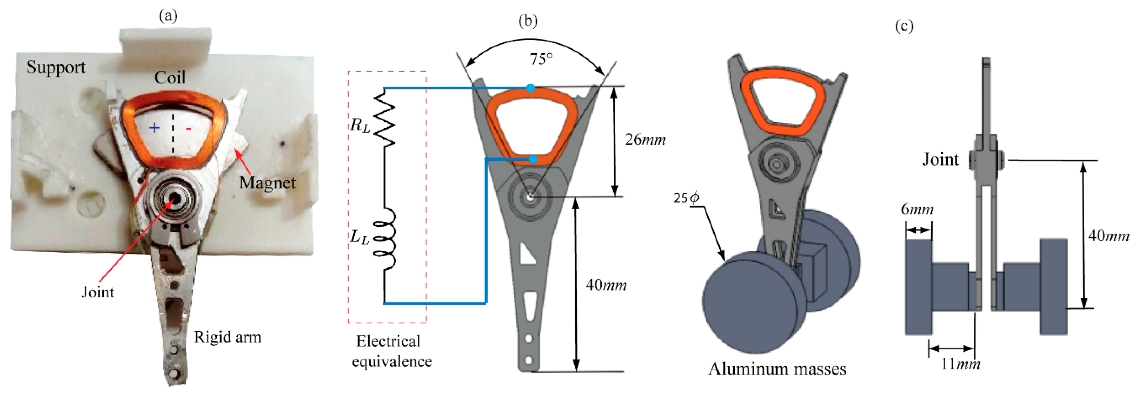
2.1. Piezo-Inductive Energy Harvester

In this section, an electrical impedance model for an energy harvester is presented in order to convert the kinetic energy to electrical energy through a piezoelectric transducer (PT), and a coil as illustrated in Figure 1. The transduction system is established as piezo-inductive since it is represented by an equivalent electrical circuit connected in series that is composed of an inductance, a resistance, and a capacitance. The coil is denoted by the inductance and resistance (in series), and the PT by the capacitance [34]. The electrical constants as inductance, resistance, and capacitance can be identified through a parameter identifier device, and these are therefore assumed as known values.
In a power generation process induced by a vibration-based generator, the performance (input mechanical/output electrical) depends on the transduction capacity of the electrical elements and the interaction between these. The transduction generates an alternating electrical potential V s ( ω t ) that makes a current (AC) i ( ω t + ϕ ) flow into the load circuit or load resistance, as shown in Figure 1. ω is the frequency, t is the time, and ϕ is the phase angle. Following the electrical circuits theory, an inductor can be represented with the following electrical impedance [35]:
Z L = R L + X L i ,
where i = 1 , R L is the electrical resistance of the inductor, X L = ω L is the inductive reactance, and L is the inductance. For the piezoelectric transducer, [34] showed that it can be considered as a capacitive element, then it presents a capacitive reactance given by
Z C = 0 + X C i .
X C = 1 / ω C and C is the capacitance. In Figure 1, the load resistance R D is represented, which will be called by its impedance as Z 2 . This is found in a parallel configuration with the impedance (harvester device) given by Z 1 = Z L + Z C . Impedance Z 2 represents a resistance that dissipates the energy produced by the generated voltage source in the electromechanical transduction. The equivalent impedance for the two impedances in parallel is determined as follows:
Z T ( ω ) = Z 1 Z 2 Z 1 + Z 2 ,
where Z 1 and Z 2 are given by
Z 1 = R L + j ( X L X C ) ,
and Z 2 = R D . Therefore, the total impedance is calculated by
Z T = ( R L + j X L j X C ) R D R L + j X L j X C + R D .
Reorganizing the Equation (5), we have that
Z T = R L R D + j R D ( X L X C ) ( R L + R D ) + j ( X L X C ) .
Multiplying by the conjugate and considering that Δ X = X L X C , it is determined that
Z T = R L R D + j R D Δ X ( R L + R D ) + j Δ X [ ( R 1 + R L ) j Δ X ( R 1 + R L ) j Δ X ] .
After developing the previous formula and separate the real part of the imaginary part, the total impedance of the electrical circuit can be represented as follows:
Z T = ( R L + R D ) ( R L R D ) + R D Δ X 2 ( R L + R D ) 2 + Δ X 2 j [ R L R D Δ X + ( R L + R D ) ( R L Δ X ) ( R L + R D ) 2 + Δ X 2 ] .
It is observed in Equation (8) that the total impedance is represented in its complex form, so for the calculation of the current, it is necessary to calculate the magnitude of Z T as follows:
| Z T | = [ ( R L + R D ) ( R L R D ) + R D Δ X 2 ( R L + R D ) 2 + Δ X 2 ] 2 + [ R L R D Δ X + ( R L + R D ) ( R D Δ X ) ( R L + R D ) 2 + Δ X 2 ] 2 .
Once the magnitude of the total impedance is obtained, the current that passes through the device is calculated by applying Ohms’ law.
I s = V s Z T ,
Equation (10) shows how an alternant current systems can be represented as direct current systems through its electrical impedance. These concepts will be applied experimentally in later sections. For the calculation of the apparent power, the equation P = V s I s was used, V s being the voltage output and Z T the equivalent electrical impedance.

2.2. Energy Harvesting Device

In order to transform mechanical energy into electrical energy, an I-VEH was built from an electromechanical system of electromagnetic transduction recycled from a hard disk (HDD). This system is commonly called a voice coil motor, as described by [26,36]. The I-VEH is composed of the following parts: the principal arm contains a coil located in the upper part, and this coil is constructed with a 33-gauge copper wire (0.18 mm) with approximately 180 turns. The support is made of a Polylactide (PLA), which includes a Neodymium magnet, all of which are described in Figure 2a.
In the I-VEH, the elements are assembled in the following way: the arm is connected through a bearing with the base. It creates a rotation joint between the base and the arm, which allows angular motions in the arm, and in this way, the coil produces electromagnetic transduction. Further, the electromechanical system can be used as an actuator. For this case, the arm motions are controlled by an electrical current that excites the coil. An additional way to use the system is as a sensor device, an approach that will be used in our experiments, since the electrical signal generated will be measured in the coil. In this way, harvester activation depends on the dynamics excitation of the arm, which is produced by an external force induced on the base. This principle allows the device to act as an energy harvesting system [17,37].
Figure 2b describes the equivalent electrical circuit of the coil represented by resistive and inductive elements connected in series. Figure 2c,d show the inertial and dimensional characteristics of the I-VEH. A set of masses were added to increase the inertia, and in this way, the device can oscillate more efficiently when the base is dynamically stimulated. Therefore, six masses were added to the arm end. The inertial elements bonded to the oscillator represented 20.8 grams (three masses) of mass, and these were placed on both sides at the bottom end of the rigid arm.

2.3. Experimental Setup and Energy Harvesting Configurations

For a first experimental configuration, the I-VEH is located such that it oscillates when the base is dynamically excited in the rotation plane of the arm, as shown in Figure 3. The motions on the base are controlled by an electrodynamic shaker that generates mechanical vibrations of constant amplitude and variable frequency. The shaker includes an internal power amplifier in order to control the displacements of the excitation. The device is activated by a swept signal between 0 Hz to 15 Hz applied linearly in the time interval of 20 s. A data acquisition system (DAQ) NI USB 6211 acquires and writes the electrical signals. The shaker was connected to an analog output of the DAQ system for the dynamic excitation, and the coil was connected to an analog input for the measurement of the electric potential. The excitation signal is commonly referred to as chirp signal since it varies in frequency and time. The generated voltage by the harvesting device was read directly into the buffer of the DAQ system.
Three experiments in different configurations or experimental modes were performed, as shown in Figure 4. The first experiment is called the inductive mode since only the I-VEH is considered. This configuration generates energy when the coil moves on the magnetic field. [38] used this technique to generate power from human gait. For this configuration, inertial elements such as beams and masses were added to the whole system.
Beams of the following lengths—9 cm, 12 cm, 15 cm, 18 cm, and 21 cm—were chosen, all with 6 mm of width and made of polystyrene. Masses on both ends of the beam were attached to perform two tests—one test with a single mass on the free end, and another test with masses on both ends. [39] demonstrated that a vibrational energy harvester could be improved through the addition of masses to the piezoelectric beams. Therefore, understanding the effects of the beams and masses on the harvesting energy process is an important aspect.
For the second experiment, an IM-VEH configuration was established. It consisted of the addition of magnetic instabilities by placing magnets at different angles as follows: 125°, 110°, and 95°. The instabilities induce external forces that are generated by the interaction of the magnets that repel each other. This causes a magnetic spring effect when the device oscillates from one side to the another. A third experiment was carried out with the selected configurations from the other two previous tests. This selection is based on electrical performance. For the third experimental test, a piezoelectric transducer was added to the base of the beam with the aim to convert the harvester to a piezo-inductive configuration. The piezoelectric transducer used is a lead zirconate titanate (PZT) SEN10293 ROHS (SparkFun Electronics, Niwot, CO, USA) that is widely applied in sensor design due to its electromechanical properties [40,41]. The transducer film was cut and attached with a cyanoacrylate instant adhesive Loctite 495 (Henkelstr, Düsseldorf, Germany). A serial connection is defined for the electrical circuit formed by the inductive and piezoelectric elements. The parallel connection presented a low-voltage output with respect to the series connection. Therefore, it was not considered in this work. Beams with piezoelectric materials have been studied in the energy harvesting by different authors from the last few years [27,42,43].

3. Results and Discussion

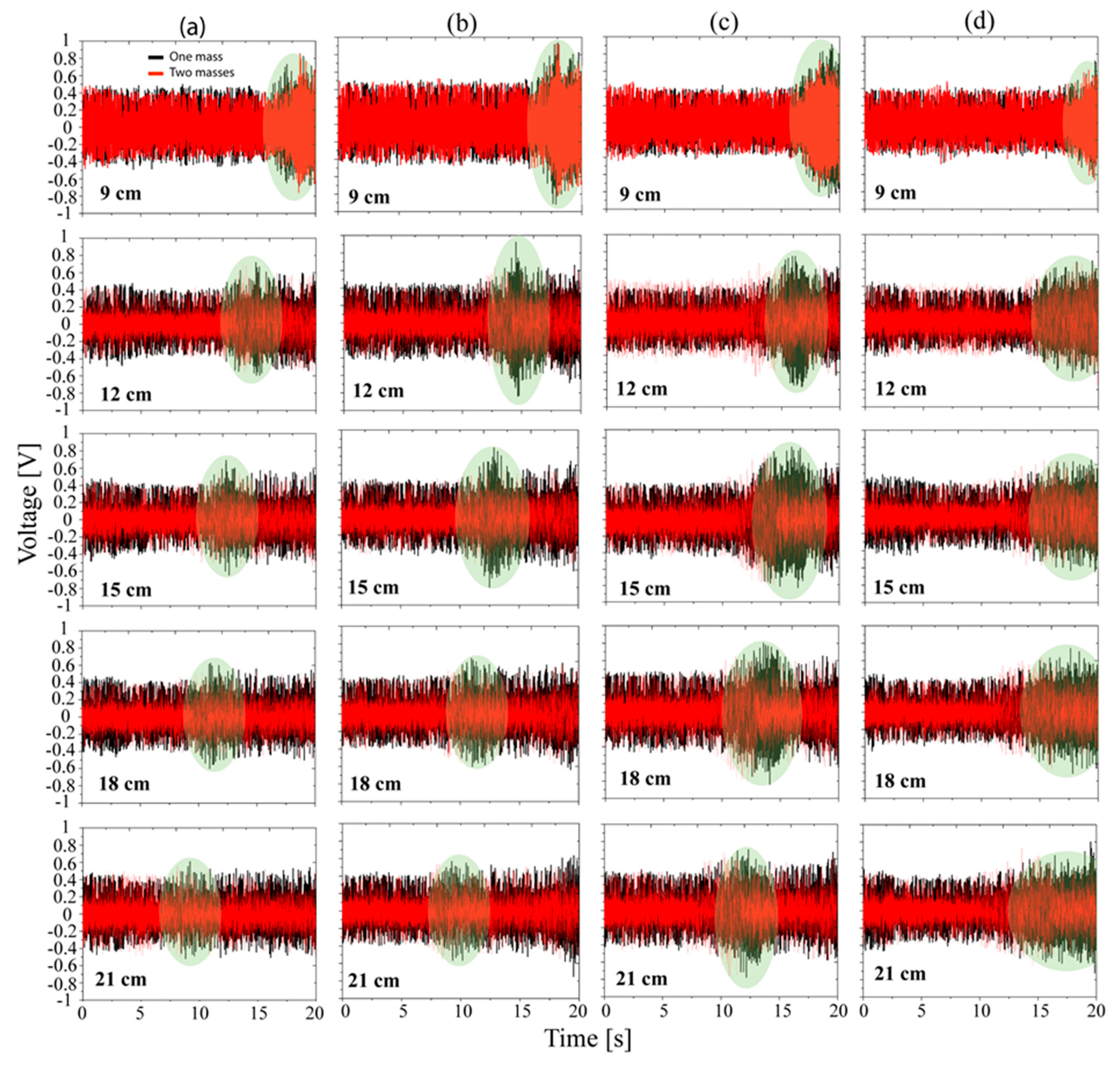
3.1. Voltage Measurements for the Experiments I and II

Figure 5 shows the results in the time domain for experiments I and II. The voltages generated by the mechanical vibrations between 0 and 15 Hz for 20 s are observed. The figure is organized into columns corresponding to each experiment performed in inductive mode (I), inductive mode with magnets (II) to 125°, 110°, and 95° degrees (b, c, and d). Each experiment was carried out with the addition of one and two masses, including the combination of five beam lengths—9 cm, 12 cm, 15 cm, 18 cm, and 21 cm. In experiment I, it is seen a maximum peak close to 18 s associated with the beam of 9 cm, the first image of Figure 5a, and it corresponds with its mechanical resonance, as posteriorly is shown in Figure 6. It is shown that this peak is shifted to the left while the length is greater than 9 cm, as demarked by the green ellipses in Figure 5. It is noted that, for 21 cm, the peak is close to 8 s. The results confirm the dependency on the stiffness in the dynamics of the whole system. A similar effect is observed for the other columns (b, c, and d), where the peaks are moving toward the left side of the time axis. It is noticed that the electrical efficiency (higher voltage) of the system with one mass is higher than the system with both masses. However, this will be verified in the frequency response analysis.
For the same length (rows in Figure 5), the voltage amplitude increased with the addition of the magnetic instabilities, as noted for 125° and 110°. The results of test I and II (95°) are comparable to each other, and both presented output voltages lower than the cases 110° and 125° in the resonances. Additionally, it is observed that for 110° (column c), the voltage has a slightly higher range corresponding with a higher bandwidth in frequency response, compared to the other experiments, being a positive contribution to the energy harvesting.

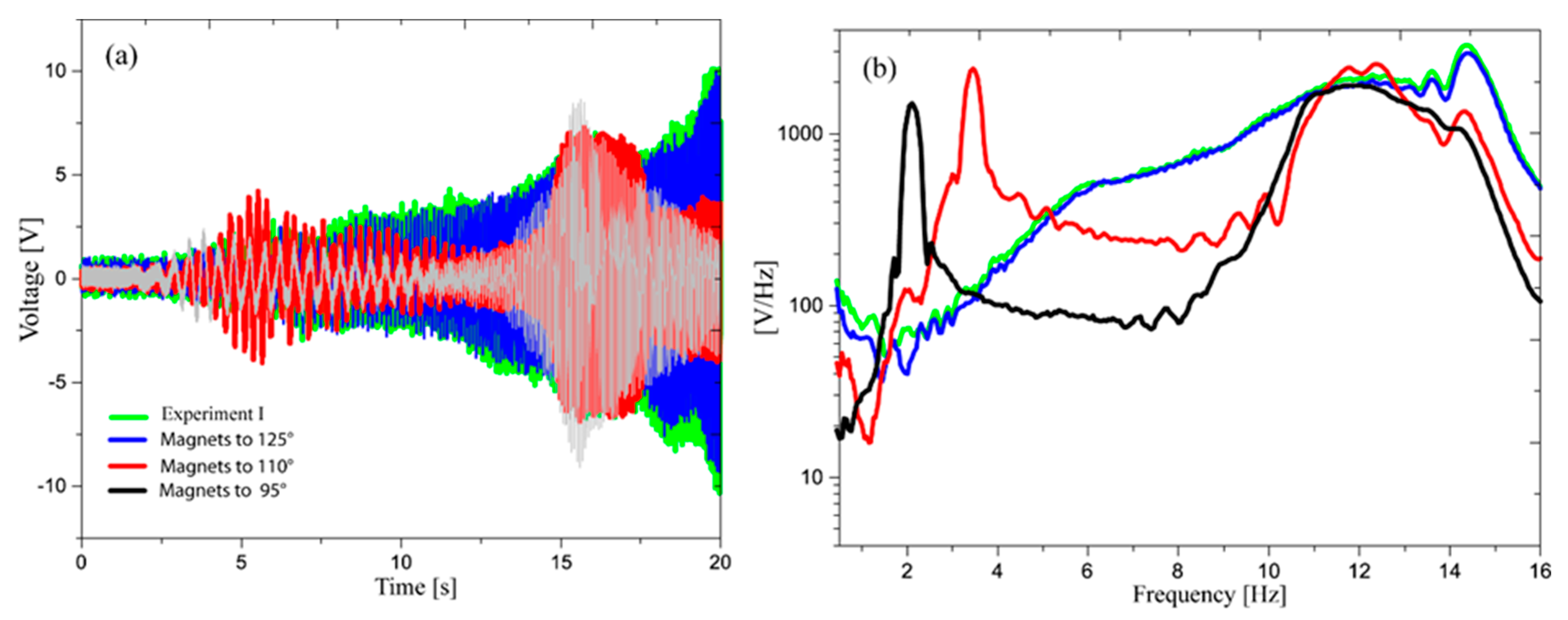
3.2. Frequency Response Analysis of the Voltage Signals

To obtain the frequency response functions of the generated voltage, the fast Fourier transform to all the signals (time domain) was applied, as illustrated in Figure 6. This shows all experiments involved in the inductive mode (I and II). For the test I (first row in the figure), there is noted how the resonance peaks are distributed through the frequency spectrum, it indicates that if the beam is longer, the associated resonance frequency is lower. This result is consistent with the representation in the time domain (Figure 5). The beam of 9 cm showed higher electrical performance in all study cases except for 95°, in which it is observed that the resonance frequency is close to 14 Hz. The lower electrical performance was registered for the beam of 21 cm (Exp. I). In the results corresponding to the experiment II with magnets located to 125°, the resonance peaks reduce the distance between these. In general, similar behavior is observed when the angle of the magnets decreases. This means that the resonance peaks are closer when the magnets are located in smaller angles.
We can point out that the highest voltage output corresponds to the experiment with magnets placed at 110° (one mass case). For the test with magnets located to 95°, all frequency response functions presented a similar trend. This means that the mechanical system (beam with masses) loses dependency on the dynamic constants (stiffness, mass) since the external forces generated by the magnets govern its behavior. This indicates independence from the inertial variations.
As a conclusion, we can mention that the magnets improved the electrical performance of the energy harvester when these were located at 110°. The effects by the addition of two masses can be identified by a small decreasing in the resonance frequency values and the diminishing of the amplitudes with respect to one mass. In the particular case of 9 cm, the addition of two masses generated an effect over the resonance observed close to 5 Hz, since a new resonance peak appeared, and it was amplified.
Figure 7 shows the root mean square (RMS) value of the output voltage shown in Figure 5 to evaluate the electrical performance of the experiments I and II. In Figure 7, the higher RMS voltages of each experiment are demarked with a red dot. Figure 7a,b refer to both inertial cases—one mass and two masses. It can be concluded that the electrical efficiency of the harvester is much lower when two masses are added to the system.

3.3. Results in the Piezo-Inductive Mode

For this experiment, a piezoelectric element was added to the tests that presented higher RMS voltages in each experiment—specifically, those that had a higher electrical performance with one mass. According to Figure 7a, the selected configurations are a beam of 9 cm for Exp. I (inductive) and II (magnets to 125°), a beam of 15 cm for exp. II (magnets to 110°), and a beam of 21 cm for exp. II (magnets to 95°), respectively.
A series connection was defined to capture the energy in the piezo-inductive mode. This connection is represented by the harvester coil and the piezoelectric element located on the base of the beam as described in Figure 4. We point out that the voltage amplitudes were very low for the parallel connection, which was evidenced by means of non-reported experimental tests. Therefore, this electrical configuration was disregarded for this study. Figure 8a shows the output voltage of selected experiments from Figure 7a. In Figure 8, it can be seen how the voltage amplitudes increased since it generated about 10 V in its maximum performance. Two different effects are remarked upon: the first one is related to a system without resonance, and the second effect is associated with a multi-resonant system.
A similar behavior can be seen for the tests I and I (125°). In the time domain, any resonant peak is evidenced, so this can be verified in the frequency spectrum. However, these configurations expose the voltage in broadband, as shown in the frequency spectrum. We can observe it in the frequency interval of 6 Hz until 14 Hz.
The other results show a multi-resonant nature in which two resonance peaks are identified—one close to 5s, and the another to 15s. Observing in the frequency domain, these correspond approximately to 3.5 Hz and 12 Hz. For the case of 95°, these peaks are found in 2 Hz and 12 Hz. It is seen that the addition of piezoelectric element amplified the voltage in all experiments. In terms of energy harvesting, this is evidently is an advantage.
Figure 9 shows the power density obtained from the selected experiments in piezo-inductive mode. The power density is computed for the series circuit between the piezoelectric element and the coil; it refers to the power divided by the length of the beam plus the size of the support. The power density values were obtained for a frequency range between 0 Hz and 15 Hz and for a variable load resistance ( R D values in between 10 Ohms and 300 Ohms as explained in Section 2.1). Figure 9a corresponds to the inductive configuration (beam of 9 cm). Figure 9b–d correspond to the experiment II that includes magnets located to 125°, 110° and 95° for beams of 9 cm, 15 cm and 21 cm, respectively. For the experiment without magnets, the highest values of the power density are close to 15 Hz, and slightly exceeding 0.04 W/cm. For the test with magnets to 125 ° (Figure 9b), the results present the same characteristics and behavior than those reported in Figure 9a. The mentioned configurations (9a and 9b) show a bandwidth from 10–15 Hz with power densities higher than 0.01 W/cm. The frequency bandwidth can be considered an advantage if the excitation is found inside the frequency interval in which the energy harvesting is maximized.
For the shown cases in Figure 9c,d, higher power density values are identified at frequencies close to 4 and 12 Hz with densities higher than 0.01 W/cm. Apparently, these configurations present the same electrical efficiency as the cases illustrated Figure 9a,b. Further, it is observed that both systems (9c and 9d) show a bandwidth in each resonance, but these are small compared with the cases of Figure 9a,b. The relevance of these results is the multi-resonant nature of the systems. In general terms, the selection of the energy harvesting system will depend on the searched application. However, it is essential to design these according to electrical efficiency.

4. Conclusions

The evaluation of an energy harvesting device with piezo-inductive technology was proposed in this study, and it was able to capture vibrations between 0 and 15 Hz. The experimental parametric analysis showed differences in the electrical performances when geometrical, inertial, and equilibrium (external forces) conditions were varied. In the inductive mode, the results evidenced that the correlations between the frequency and the beam lengths could be used as a design tool if the resonance of the device matches with a particular excitation frequency. For example, the resonance frequency shifted to the left when the beam lengths were higher, which means that the stiffness of the beams decreased. Furthermore, it was observed how magnetic instabilities introduced different effects, i.e., voltage amplitude increased with respect to the inductive mode when magnets were located to 125° and 110° (one mass case). In the case of 95°, the signals showed similar trends, almost converting it in an invariant system to the inertial variations. This means that the energy harvesting mechanism was governed by the magnetic interactions and not by the length of the beams, including its masses.
In the piezo-inductive mode, the combination of both transducers achieved higher electrical performances, since the inductive element (the coil) captured energy from rotations (kinetic energy) and the piezoelectric material from the beam strains (strain energy). The voltages increased when the piezoelectric element was added to the system, showing voltages higher up to 20 times with respect to inductive mode. As a final result, this provided higher power density delivered by the harvesting device, as electrical simulation demonstrated.

Author Contributions

Conceptualization, H.A.T. and C.A.V.; methodology, H.A.T. and C.A.V.; software, C.A.V.; validation, C.A.V.; formal analysis, H.A.T.; investigation, H.A.T. and C.A.V.; writing—original draft preparation, H.A.T. and C.A.V.; writing—review and editing, H.A.T. and C.A.V.; visualization, H.A.T.; supervision, H.A.T.; project administration, H.A.T.; funding acquisition, H.A.T. and C.A.V.

Funding

This research received no external funding

Conflicts of Interest

The authors declare no conflict of interest.

References

  1. Choi, W.J.; Jeon, Y.; Jeong, J.H.; Sood, R.; Kim, S.G. Energy Harvesting MEMS Device Based on Thin Film Piezoelectric Cantilevers. J. Electroceram. 2006, 17, 543–548. [Google Scholar] [CrossRef]
  2. Kamalinejad, P.; Mahapatra, C.; Sheng, Z.; Mirabbasi, S.; Leung, V.C.; Guan, Y.L. Wireless energy harvesting for the Internet of Things. IEEE Commun. Mag. 2015, 53, 102–108. [Google Scholar] [CrossRef] [Green Version]
  3. Penella, M.T.; Gasulla, M. A Review of Commercial Energy Harvesters for Autonomous Sensors. In Proceedings of the IEEE Instrumentation & Measurement Technology Conference (IMTC 2007), Warsaw, Poland, 1–3 May 2007; pp. 1–5. [Google Scholar]
  4. Caliò, R.; Rongala, U.; Camboni, D.; Milazzo, M.; Stefanini, C.; De Petris, G.; Oddo, C. Piezoelectric energy harvesting solutions. Sensors 2014, 14, 4755–4790. [Google Scholar] [CrossRef] [PubMed]
  5. Vullers, R.J.; Van Schaijk, R.; Visser, H.J.; Penders, J.; Van Hoof, C. Energy harvesting for autonomous wireless sensor networks. IEEE Solid-State Circuits Mag. 2010, 2, 29–38. [Google Scholar] [CrossRef]
  6. Kausar, A.Z.; Reza, A.W.; Saleh, M.U.; Ramiah, H. Energizing wireless sensor networks by energy harvesting systems: Scopes, challenges and approaches. Renew. Sustain. Energy Rev. 2014, 38, 973–989. [Google Scholar] [CrossRef]
  7. Sudevalayam, S.; Kulkarni, P. Energy harvesting sensor nodes: Survey and implications. IEEE Commun. Surv. Tutor. 2010, 13, 443–461. [Google Scholar] [CrossRef]
  8. Kim, H.S.; Kim, J.H.; Kim, J. A review of piezoelectric energy harvesting based on vibration. Int. J. Precis. Eng. Manuf. 2011, 12, 1129–1141. [Google Scholar] [CrossRef]
  9. Chalasani, S.; Conrad, J.M. A survey of energy harvesting sources for embedded systems. In Proceedings of the IEEE SoutheastCon 2008, Huntsville, AL, USA, 3 April 2008; pp. 442–447. [Google Scholar]
  10. Sriramdas, R.; Pratap, R. Performance analysis of hybrid vibrational energy harvesters with experimental verification. Smart Mater. Struct. 2018, 27, 075008. [Google Scholar] [CrossRef]
  11. Beeby, S.P.; Tudor, M.J.; White, N.M. Energy harvesting vibration sources for microsystems applications. Meas. Sci. Technol. 2006, 17, R175. [Google Scholar] [CrossRef]
  12. Shu, Y.C.; Lien, I.C. Analysis of power output for piezoelectric energy harvesting systems. Smart Mater. Struct. 2006, 15, 1499. [Google Scholar] [CrossRef]
  13. Cottone, F.; Vocca, H.; Gammaitoni, L. Nonlinear energy harvesting. Phys. Rev. Lett. 2009, 102, 080601. [Google Scholar] [CrossRef] [PubMed]
  14. Büren, T.V. Body-Worn Inertial Electromagnetic Micro-Generators. Doctoral Dissertation, ETH Zurich, Zurich, Switzerland, 2006. [Google Scholar]
  15. Fang, H.B.; Liu, J.Q.; Xu, Z.Y.; Dong, L.; Wang, L.; Chen, D.; Cai, B.C.; Liu, Y. Fabrication and performance of MEMS-based piezoelectric power generator for vibration energy harvesting. Microelectron. J. 2006, 37, 1280–1284. [Google Scholar] [CrossRef]
  16. Tang, L.; Yang, Y.; Soh, C.K. Toward broadband vibration-based energy harvesting. J. Intell. Mater. Syst. Struct. 2010, 21, 1867–1897. [Google Scholar] [CrossRef]
  17. Zhu, D. Vibration energy harvesting: Machinery vibration. In Sustainable Energy Harvesting Technologies-Past, Present and Future; IntechOpen: Rijeka, Croatia, 2011. [Google Scholar]
  18. Nintanavongsa, P.; Muncuk, U.; Lewis, D.R.; Chowdhury, K.R. Design optimization and implementation for RF energy harvesting circuits. IEEE J. Emerg. Sel. Top. Circuits Syst. 2012, 2, 24–33. [Google Scholar] [CrossRef]
  19. Liu, J.Q.; Fang, H.B.; Xu, Z.Y.; Mao, X.H.; Shen, X.C.; Chen, D.; Liao, H.; Cai, B.C. A MEMS-based piezoelectric power generator array for vibration energy harvesting. Microelectron. J. 2008, 39, 802–806. [Google Scholar] [CrossRef]
  20. Scapolan, M.; Tehrani, M.G.; Bonisoli, E. Energy harvesting using parametric resonant system due to time-varying damping. Mech. Syst. Signal Process. 2016, 79, 149–165. [Google Scholar] [CrossRef]
  21. Leland, E.S.; Wright, P.K. Resonance tuning of piezoelectric vibration energy scavenging generators using compressive axial preload. Smart Mater. Struct. 2006, 15, 1413. [Google Scholar] [CrossRef]
  22. Shen, D.; Park, J.H.; Noh, J.H.; Choe, S.Y.; Kim, S.H.; Wikle, H.C., III; Kim, D.J. Micromachined PZT cantilever based on SOI structure for low frequency vibration energy harvesting. Sens. Actuators A Phys. 2009, 154, 103–108. [Google Scholar] [CrossRef]
  23. Renaud, M.; Fiorini, P.; van Schaijk, R.; Van Hoof, C. Harvesting energy from the motion of human limbs: The design and analysis of an impact-based piezoelectric generator. Smart Mater. Struct. 2009, 18, 035001. [Google Scholar] [CrossRef]
  24. Papagiannakis, A.T.; Dessouky, S.; Montoya, A.; Roshani, H. Energy harvesting from roadways. Procedia Comput. Sci. 2016, 83, 758–765. [Google Scholar] [CrossRef]
  25. Tinoco, H.A. Beam design for voice coil motors used for energy harvesting purpose with low frequency vibrations: A finite element analysis. Int. J. Model. Simul. Sci. Comput. 2016, 7, 1640001. [Google Scholar] [CrossRef]
  26. Tinoco, H.A.; Garcia-Diaz, C.; Ocampo-Lopez, O.L. Performance Assessment in a Voice Coil Motor for Maximizing the Energy Harvesting with Gait Motions. World Acad. Sci. Eng. Technol. Int. J. Electr. Comput. Energ. Electron. Commun. Eng. 2017, 1, 133–137. [Google Scholar]
  27. Nabavi, S.F.; Farshidianfar, A.; Afsharfard, A. Novel piezoelectric-based ocean wave energy harvesting from offshore buoys. Appl. Ocean Res. 2018, 76, 174–183. [Google Scholar] [CrossRef]
  28. Eun, Y.; Kwon, D.S.; Kim, M.O.; Yoo, I.; Sim, J.; Ko, H.J.; Cho, K.H.; Kim, J. A flexible hybrid strain energy harvester using piezoelectric and electrostatic conversion. Smart Mater. Struct. 2014, 23, 045040. [Google Scholar] [CrossRef]
  29. Toyabur, R.M.; Salauddin, M.; Park, J.Y. Design and experiment of piezoelectric multimodal energy harvester for low frequency vibration. Ceram. Int. 2017, 43, S675–S681. [Google Scholar] [CrossRef]
  30. Fan, K.; Tan, Q.; Zhang, Y.; Liu, S.; Cai, M.; Zhu, Y. A monostable piezoelectric energy harvester for broadband low-level excitations. Appl. Phys. Lett. 2018, 112, 123901. [Google Scholar] [CrossRef]
  31. Edwards, B.; Hu, P.A.; Aw, K.C. Validation of a hybrid electromagnetic–piezoelectric vibration energy harvester. Smart Mater. Struct. 2016, 25, 055019. [Google Scholar] [CrossRef]
  32. Hamid, R.; Yuce, M.R. A wearable energy harvester unit using piezoelectric–electromagnetic hybrid technique. Sens. Actuators A Phys. 2017, 257, 198–207. [Google Scholar] [CrossRef]
  33. Du, X.; Zhao, S.; Xing, Y.; Li, N.; Wang, J.; Zhang, X.; Cao, R.; Liu, Y.; Yuan, Z.; Yin, Y.; et al. Hybridized Nanogenerators for Harvesting Vibrational Energy by Triboelectric–Piezoelectric–Electromagnetic Effects. Adv. Mater. Technol. 2018, 3, 1800019. [Google Scholar] [CrossRef]
  34. Sirohi, J.; Chopra, I. Fundamental understanding of piezoelectric strain sensors. J. Intell. Mater. Syst. Struct. 2000, 11, 246–257. [Google Scholar] [CrossRef]
  35. Boylestad, R.L. Introducción Al Análisis de Circuitos; Prentice Hall: Decimosegu, Mexico, 2011. [Google Scholar]
  36. Roundy, S.; Wright, P.K.; Rabaey, J. A study of low level vibrations as a power source for wireless sensor nodes. Comput. Commun. 2003, 26, 1131–1144. [Google Scholar] [CrossRef]
  37. Banerji, S.; Bagchi, A.; Khazaeli, S. STR-991: Energy Harvesting Methods for structural health monitoring using wireless sensors: A review. In Proceedings of the Canadian Society for Civil Engineering Annual Conference, London, ON, Canada, 1–4 June 2016. [Google Scholar]
  38. Ylli, K.; Hoffmann, D.; Willmann, A.; Becker, P.; Folkmer, B.; Manoli, Y. Energy harvesting from human motion: Exploiting swing and shock excitations. Smart Mater. Struct. 2015, 24, 025029. [Google Scholar] [CrossRef]
  39. Sneller, A.J.; Cette, P.; Mann, B.P. Experimental investigation of a post-buckled piezoelectric beam with an attached central mass used to harvest energy. Proc. Inst. Mech. Eng. Part I J. Syst. Control Eng. 2011, 225, 497–509. [Google Scholar] [CrossRef]
  40. Shrout, T.R.; Zhang, S.J. Lead-free piezoelectric ceramics: Alternatives for PZT? J. Electroceram. 2007, 19, 113–126. [Google Scholar] [CrossRef]
  41. Tinoco, H.; Cardona, C.; Peña, F.; Gomez, J.; Roldan-Restrepo, S.; Velasco-Mejia, M.; Barco, D. Evaluation of a piezo-actuated sensor for monitoring elastic variations of its support with impedance-based measurements. Sensors 2019, 19, 184. [Google Scholar] [CrossRef] [PubMed]
  42. Erturk, A.; Tarazaga, P.A.; Farmer, J.R.; Inman, D.J. Effect of strain nodes and electrode configuration on piezoelectric energy harvesting from cantilevered beams. J. Vib. Acoust. 2009, 131, 011010. [Google Scholar] [CrossRef]
  43. Lee, S.; Youn, B.D. A new piezoelectric energy harvesting design concept: Multimodal energy harvesting skin. IEEE Trans. Ultrason. Ferroelectr. Freq. Control 2011, 58, 629–645. [Google Scholar] [CrossRef]
Figure 1. Schematic representation of the piezo-inductive device with the load resistance.
Actuators 08 00055 g001
Figure 2. Principal components of the energy harvester. (a) Transduction system. (b) Inductive electrical scheme. (c) 3D model with dimensions in mm.
Actuators 08 00055 g002
Figure 3. Representation of Experimental setup indicating the chirp signal received by shaker through a data acquisition system (DAQ).
Actuators 08 00055 g003
Figure 4. Experimental methodology composed by: Experiment I with an I-VEH; experiment II with an IM-VEH, and experiment II with a PI-VEH.
Actuators 08 00055 g004
Figure 5. Output voltage for: (a) Inductive mode (Experiment I). Inductive mode with magnetic instabilities (Experiment II) located in the following angles: (b) 125 °, (c) 110°, (d) 95°.
Actuators 08 00055 g005
Figure 6. Frequency response functions for experiments I and II. Column (a) represents experiments with one mass for inductive mode and magnets located to 125 °, 110 °, and 95 °. Column (b) represents the experiments with two masses.
Actuators 08 00055 g006
Figure 7. RMS voltage output for experiments I (inductive mode), II (magnets to 125°, 110°, and 95°): (a) One mass. (b) Two masses.
Actuators 08 00055 g007
Figure 8. Experiment III (piezo-inductive mode) performed with corresponding selected tests to inductive mode I and magnets to 125°, 110°, and 95°. (a) Output voltage. (b) Frequency response function.
Actuators 08 00055 g008
Figure 9. Power density for an electrical load resistance 0–300 Ohms. (a) Inductive mode for the beam of 9 cm. (b) Magnets to 125° with a beam of 9 cm. (c) Magnets to 110° with a beam of 15 cm. (d) Magnets to 95° with a beam of 21 cm.
Actuators 08 00055 g009

