Article

Analysis and Control of Slotless Self-Bearing Motor

1
Institute for Control Engineering and Automation, Hanoi University of Science and Technology, Hanoi 100000, Vietnam
2
Department of Electrical Engineering, Vinh University of Technology Education, Nghe An 460000, Vietnam
3
Department of Mechanical Engineering, Ritsumeikan University, Kusatsu 525-8577, Japan
*
Author to whom correspondence should be addressed.
Actuators 2019, 8(3), 57; https://doi.org/10.3390/act8030057
Submission received: 6 June 2019 / Revised: 10 July 2019 / Accepted: 17 July 2019 / Published: 19 July 2019

Abstract

:
A self-bearing motor (SBM) is an electric motor with a magnetically integrated bearing function, that is, it can provide levitation and rotation simultaneously as a single actuator. This paper presents the design, operating principle and control system for the slotless self-bearing motor (SSBM). In this design, the stator has no iron core but includes six-phase coils. The rotor consists of a permanent magnet and an enclosed iron yoke. Magnetic forces generated by the interaction between stator currents and the magnetic field of the permanent magnet are used to control the rotational speed and radial position of the rotor. In this paper, the torque and radial bearing forces are analyzed theoretically with the aim to develop an improved control system. In order to confirm the proposed control method, an experimental system was constructed and tested. Simulation and measurement results show that the SSBM can work stably in modes such as start, reverse, rotation load and external radial pulse forces.

1. Introduction

Recently, the magnetic bearing motor, with its non-contact levitating capability, has been of more and more interest to many researchers, thanks to its advantages such as no friction loss, no abrasion and lubrication-free operation. Conventional magnetic bearing motors (Figure 1) usually consist of a rotary motor, two radial magnetic bearings to stabilize the rotor in the horizontal direction, and an axial magnetic bearing to keep the rotor stable in the axial direction. Obviously, with this structure, the magnetic bearing motor is large, heavy, suffers high losses and is difficult to apply for devices with the limited space [1,2,3].
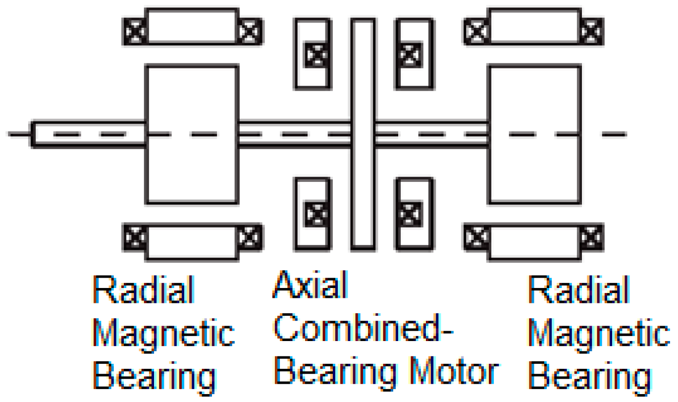
During recent years, studies have focused on reducing the size and the loss of magnetic bearing motors. One of the solutions that has drawn a lot of attention is the combination of the axial magnetic bearing to the motor [4,5,6]. An axial magnetic bearing is composed of a rotary disc fixed on a rotary shaft and electromagnets arranged on both sides of the rotary disc with a small enough gap. This structure is similar to that of the axial flux alternating current (AC) motor. Consequently, the axial gap self-bearing motor (AGBM) was introduced, as shown in Figure 2. The AGBM is an electrical combination of an axial flux motor and an axial magnetic bearing, which is simpler in structure and control than a conventional magnetic-bearing motor, since the hardware components can be reduced. However, the AGBM has lower torque density and higher material cost than the radial flux motor [7].
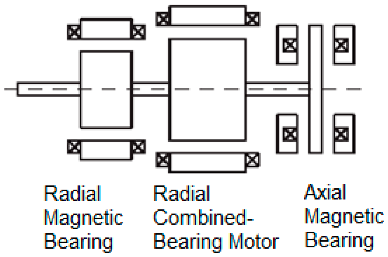
Another solution is combining the radial magnetic bearing with the motor, as illustrated in Figure 3 [8,9,10]. With the large power range, this method of combination has many advantages, such as high stability, reliability and efficiency. However, in a small power range, the requirements for increasing the power density and reducing losses are hard work because of the complexity in structure and control.
In order to overcome this drawback, the slotless, bearingless motors, which still assure the ability to generate rotation and radial movement, have been introduced recently [11,12]. These kinds of motor use toroidal iron cores, and the cooper coils are wound around the stator. By supplying a sufficient amount of the torque and bearing currents, the motor can generate force and torque simultaneously. Obviously, this structure is simpler and the motor has good passive bearing stiffness. However, the enhancement of higher efficiency is still limited because of the stator’s iron core.
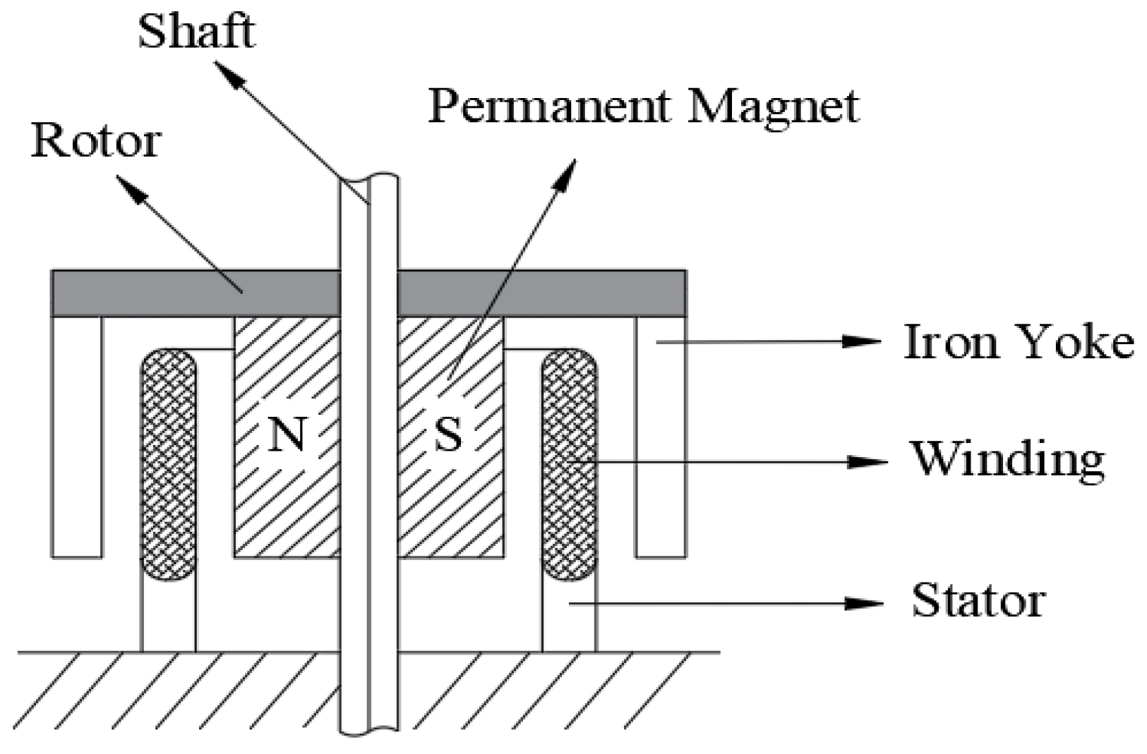
Recently, miniaturized brush and brushless ironless direct current (DC) motors have been developed [13,14]. Some examples of this motor type are available on the market (MOONS, ThinGap, Maxon). Compared to the conventional iron-core motors, the coreless types have no iron losses and acceptable thermal dissipation, which makes them extremely efficient. In addition, their linear behavior fits well with simple drive circuits. Based on the structure of the brushless ironless DC motors, a new type of slotless self-bearing motor (Figure 4) has been proposed [15,16]. By rationally arranging the stator windings and by using of superposition principle, the currents in the coil interact with magnetic field of the rotor’s permanent magnet to create torque and bearing force simultaneously. This combination makes the self-bearing motor size smaller and increases the power density, as well as performance, of the self-bearing motor. Simple open and closed-loop torque control methods have been implemented. The experimental results illustrate some characteristics of the motor. However, these control structures are simple and not suitable for modern AC motor drives, as they lead to poor dynamic and high displacement error.
Based on d-q axis current control of a bearingless motor [17,18], this paper presents improvements to the control system for the slotless self-bearing motor (SSBM), especially in updating the control structure and a suitable design method for position and speed controller. Moreover, in this manuscript, the calculation of torque and force is presented more clearly and in more detail. The design of speed and position controller by using the pole placement method is also presented to improve the performance of the SSBM. Additionally, the proposed control method and a simple experimental system have been tested.

2. Design of the Control System for the SSBM

2.1. Introduction of the SSBM

The configuration of the SSBM is illustrated in Figure 4. The rotor consists of a shaft, a cylindrical two-pole permanent magnet, a back yoke, and one part to fix them together. The air gap between the permanent magnet and iron yoke is invariable, to make sure that the unstable attractive force of the permanent magnet becomes zero. In addition, the iron yoke has a great effect on reducing energy loss. The stator consists of a six-phase distributed winding without an iron core, and is inserted between the permanent magnet and the yoke of the rotor.
The operating principle of the SSBM is shown in Figure 5. To makes it simple, the number of turns of the stator winding is illustrated as one circle, which indicates the direction of current. When the currents are applied to the stator coils, as shown in Figure 5a, a bearing force is generated. On the other hand, when the currents are supplied to the stator coils as shown in Figure 5b, a torque is generated on the rotor as a reaction force. By supplying both kinds of current as shown in Figure 5c, the torque and bearing force are generated simultaneously.

2.2. Calculation of Bearing Force and Torque

Figure 6 describes the coordinate axis used for the analysis of the bearing force and torque. Figure 6a presents the section perpendicular to the SSBM shaft, while the development along the circumference of the stator winding is shown in Figure 6b. The 6-phase coil is evenly distributed around the coordinate axis, a-phase symmetry with d-phase through the origin coordinate, b-phase symmetry with e-phase and c-phase symmetry with f-phase, respectively. The stator windings are wound according to a hexagonal frame. Hence, it can be divided into two parts: one is the parallel part, that is, parallel to the axial direction; the other comprises the top and the bottom parts of the winding, called the serial part.
The angular positions of the parallel part are expressed as follows:
p h a s e k { θ + p h a s e k = θ 0 + k 1 3 n π + 2 m 6 π θ p h a s e k = θ 0 + k 1 3 n π + 2 m + 3 6 π
where m is the coefficient corresponding to each phase, a-phase: m = 0 and f-phase: m = 5, k is the turn number, n is the total number of turns, and θ0 is the angular position of the +a-phase winding. n must be an odd number so that the wires will not overlap.
For simplicity, it is assumed that the magnetic field generated by the current is much smaller than that generated by the permanent magnet of the rotor, which means that the magnetic field in the air gap is distributed according to the sinusoidal rule and calculated as follows:
B g ( θ ) = B cos ( θ ψ )
where B is the amplitude of the magnetic flux density, and ψ is the angular position of the rotor.
The analysis only considers the pair of forces caused by two symmetric phases a and d. The bearing force has an additional symbol “f” above to distinguish it from the motor torque with the symbol “T” above.

2.2.1. Bearing Force

In order to generate the bearing force and balance the rotor, the reaction force generated by the current of two symmetrical phases must have the same direction and amplitude, as shown in Figure 7. Hence, the bearing current of two symmetrical phases must be in the same direction and amplitude.
In general, the Lorentz force for a wire loop is calculated as:
f p , ± p h a s e = B g ( θ ± p h a s e ) i p h a s e l
where l is the length of the impacted wire. The amplitudes of the Lorentz force of each phase are calculated as:
{ F + a f = F + d f = | B l i a f cos ( θ 0 ψ ) | F a f = F d f = | B l i a f sin ( θ 0 ψ ) |
where i a f is the current component which generates the bearing force of a-phase. Then, as shown in Figure 7, the total amplitude of the Lorentz force for symmetrical phase a-d is calculated as:
F a = F + a d 2 + F a d 2 = ( F + a f + F + d f ) 2 + ( F a f + F d f ) 2 = 2 B l i a f
Correspondingly, the bearing forces generated by the remaining symmetrical phase are:
F b = 2 B l i b f
F c = 2 B l i c f
In order to balance the rotor, the total amplitude of the forces must be zero, so:
i a f + i b f + i c f = 0
Hence, the bearing currents are expressed as:
{ i a , d f = i d cos ( ψ ) + i q sin ( ψ ) i b , e f = i d cos ( ψ 2 π / 3 ) + i q sin ( ψ 2 π / 3 ) i c , f f = i d cos ( ψ 4 π / 3 ) + i q sin ( ψ 4 π / 3 )
here, id is the direct axis current and iq is the quadrate axis current.

2.2.2. Torque

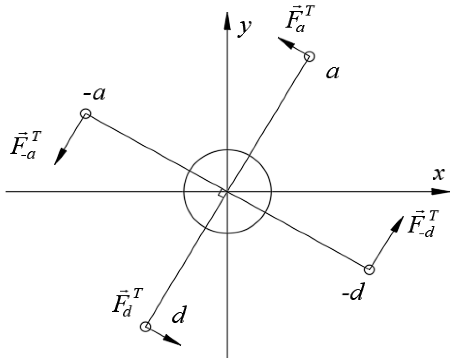
To create the motor torque, the reaction forces generated by the currents of two symmetrical phases must be in the opposite direction as shown in Figure 8. Hence, the torque currents of two symmetrical phases must be in the opposite direction. The force couples: ( F a T F d T ) and ( F a T F d T ) have the same amplitude but opposite direction, thus from the Equation (3), a relating equation is expressed as:
{ F + a T = F + d T = | B l i a T cos ( θ 0 ψ ) | F a T = F d T = | B l i a T sin ( θ 0 ψ ) |
The total torque is:
τ a = B l i a T { c o s ( θ 0 ψ ) + sin ( θ 0 ψ ) } R
where i a T is the current component which generates the torque of a-phase and R is the radius of the rotor. Correspondingly, we have:
τ b = B l i b T { c o s ( θ 0 + π 3 ψ ) + sin ( θ 0 + π 3 ψ ) } R
τ c = B l i c T { c o s ( θ 0 + 2 π 3 ψ ) + sin ( θ 0 + 2 π 3 ψ ) } R
In order for the total force acting on the rotor not to be zero, the motor currents are expressed as follows:
{ i a , d T = ± A m cos ( ϕ m ) i b , e T = ± A m cos ( ϕ m + π / 3 ) i c , f T = ± A m cos ( ϕ m + 2 π / 3 )
here, Am is the amplitude of the motor current, and ϕ m is its phase. The total current stator is the summation of Equations (8) and (14). Then, we have:
{ i a , d = i d cos ( ψ ) + i q sin ( ψ ) ± A m cos ( ϕ m ) i b , e = i d cos ( ψ 2 π / 3 ) + i q sin ( ψ 2 π / 3 ) ± A m cos ( ϕ m + π / 3 ) i c , f = i d cos ( ψ 4 π / 3 ) + i q sin ( ψ 4 π / 3 ) ± A m cos ( ϕ m + 2 π / 3 )
We combined the Equation (15) with the properties of the stator winding in order to calculate the total force acting on the rotor and the generated torque.
• The parallel component l p
The bearing force is calculated as follows:
{ f p x , ± p h a s e = f p , ± p h a s e sin ( θ ± p h a s e ) f p y , ± p h a s e = f p , ± p h a s e cos ( θ ± p h a s e )
The motor torque becomes:
τ p , ± p h a s e = r f p , ± p h a s e
here r is the radius of the winding. The total force and torque are derived from (3), (15), (16) and (17), respectively. The results are expressed as:
{ τ p = 3 2 r l p B A m sin ( ϕ m ψ + θ 0 + π / 4 ) f p x = 3 l p B { i d sin ( 2 θ 0 ) i q cos ( 2 θ 0 ) } f p y = 3 l p B { i d cos ( 2 θ 0 ) + i q sin ( 2 θ 0 ) }
• The serial component l t :
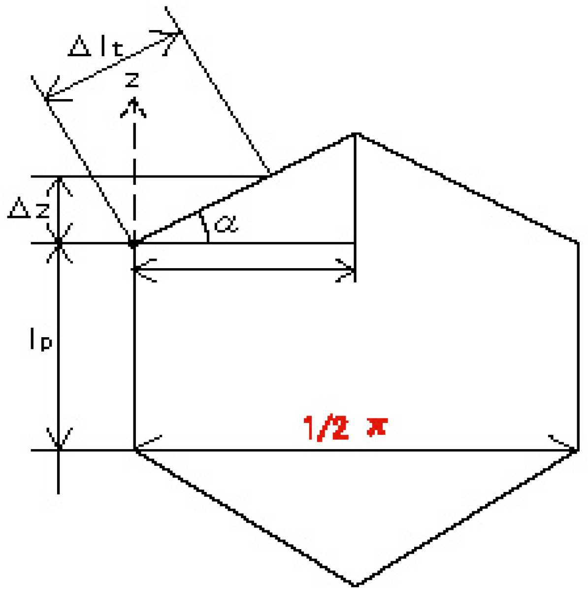
The serial components are divided into small parts depending on the variable z. Following the Figure 6, the angular position of the serial part can be expressed as follows:
{ θ t , + p h a s e ( z ) = π 4 l t z + 2 m 6 π + θ 0 θ t , p h a s e ( z ) = π 4 l t z + 2 m + 3 6 π + θ 0
where l t is the projection length of the serial part on the z-axis.
The Lorentz force of a small distance in this part is calculated as:
Δ f t , ± p h a s e = B g ( θ t , p h a s e ( z ) ) i p h a s e Δ z sin α
where α is a wire angle with its horizontal axis passing through the serial part. As illustrated in Figure 9, the α angle can be expressed as follows:
α = tan 1 θ + p h a s e θ p h a s e 2 l p r = tan 1 π r 4 l p
The Lorentz force in the serial part consists of two components in the axial direction, Δ ftz, and force in the radial direction, Δ ftt. Each force is expressed as:
Δ f t z , ± p h a s e = Δ f t , ± p h a s e cos α Δ f t t , ± p h a s e = Δ f t , ± p h a s e sin α
The force in the radial direction becomes:
Δ f t t , ± p h a s e = B g ( θ t , p h a s e ( z ) ) i p h a s e Δ z
and the torque generated by this part is calculated as:
τ t , ± p h a s e = 0 l t r f t t , ± p h a s e
Then the total torque becomes:
τ t = 4 r l t B A m π ( 6 3 2 ) sin ( ϕ m ψ + θ 0 + π / 4 )
The bearing force of each phase is calculated as follows:
{ f t x , ± p h a s e = 0 l t f t t ± p h a s e sin ( θ t ± p h a s e ( z ) ) f t y , ± p h a s e = 0 l t f t t ± p h a s e cos ( θ t ± p h a s e ( z ) )
Hence, the total bearing force is:
{ f t x = 6 l t B π { i d sin ( 2 θ 0 ) i q cos ( 2 θ 0 ) } f t y = 6 l t B π { i d cos ( 2 θ 0 ) + i q sin ( 2 θ 0 ) }
While the turn part comprises two parts, the total torque and radial force become:
{ τ = k m A m sin ( ϕ m ψ + θ 0 + π / 4 ) f x = k b { i d sin ( 2 θ 0 ) i q cos ( 2 θ 0 ) } f y = k b { i d cos ( 2 θ 0 ) + i q sin ( 2 θ 0 ) }
where:
k m = ( 3 2 l p + 8 ( 6 3 2 ) π l t ) r B k b = ( 3 l p + 12 π l t ) B
The rotating torque and radial forces in case of n turns are obtained as follows:
{ τ = k n m k m A m sin ( ϕ m ψ + θ 0 + π / 4 ) f x = k n b k b { i d sin ( 2 θ 0 ) i q cos ( 2 θ 0 ) } f y = k n b k b { i d cos ( 2 θ 0 ) + i q sin ( 2 θ 0 ) }
where knm and knb are calculated as:
k n m = 1 + 2 cos ( π 3 n ) + 2 cos ( 2 π 3 n ) + + 2 cos ( ( n 1 ) 2 π 3 n ) k n b = 1 + 2 cos ( 2 π 3 n ) + 2 cos ( 4 π 3 n ) + + 2 cos ( ( n 1 ) π 3 n )
From Equation (30), the mathematical model of the SSBM is completely constructed with force and torque equations. It can be seen that these are simple linear equations. Thus, the control system can be easily implemented with conventional controllers.

2.3. Designing the Control System

2.3.1. Control Structure

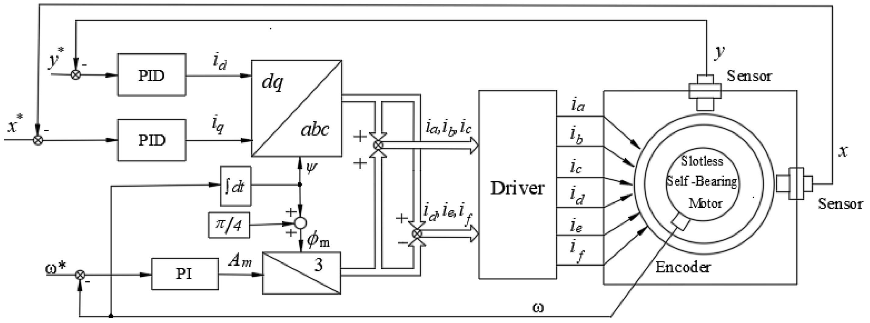
When the angular position of the rotor can be obtained, the stator current can be calculated by Equation (15), and then the force and torque can be calculated. θ0 is the angular position of the +a-phase winding so if +a-phase coincides with x-axis then θ0 = 0. ϕ m is the phase of the torque current and depends on the control strategy. To conduct the clear control algorithm, we can assume that θ 0 = 0 and ϕ m = ψ + π 4 or ϕ m ψ + θ 0 + π 4 = π 2 , then the Equation (30) becomes:
{ τ = k n m k m A m F x = k n b k b i q F y = k n b k b i d
It is easy to see that the rotating torque is produced by A m and the bearing force is produced by i d and i q . Therefore, the rotating torque can be controlled by A m and the bearing force can be controlled by i d and i q . On the other hand, the two components force and torque are mathematically independent from each other, thus, the control structure is introduced as shown in Figure 10. In this control structure a proportional-integral (PI) controller is used for the speed control, while the displacement position controller is a proportional-integral-derivative (PID).

2.3.2. Designing Speed and Position Controller

Setting: K T = k n m k m and K f x = K f y = k n b k b , the Equation (32) becomes:
{ τ = K T A m F x = K f x i q F y = K f y i d
The dynamic equation of the rotor is:
τ T l = J d ω d t
F F l = M a
where M is the weight of the rotor, a is the acceleration of the rotor, Tl is the load torque and Fl is the load force.
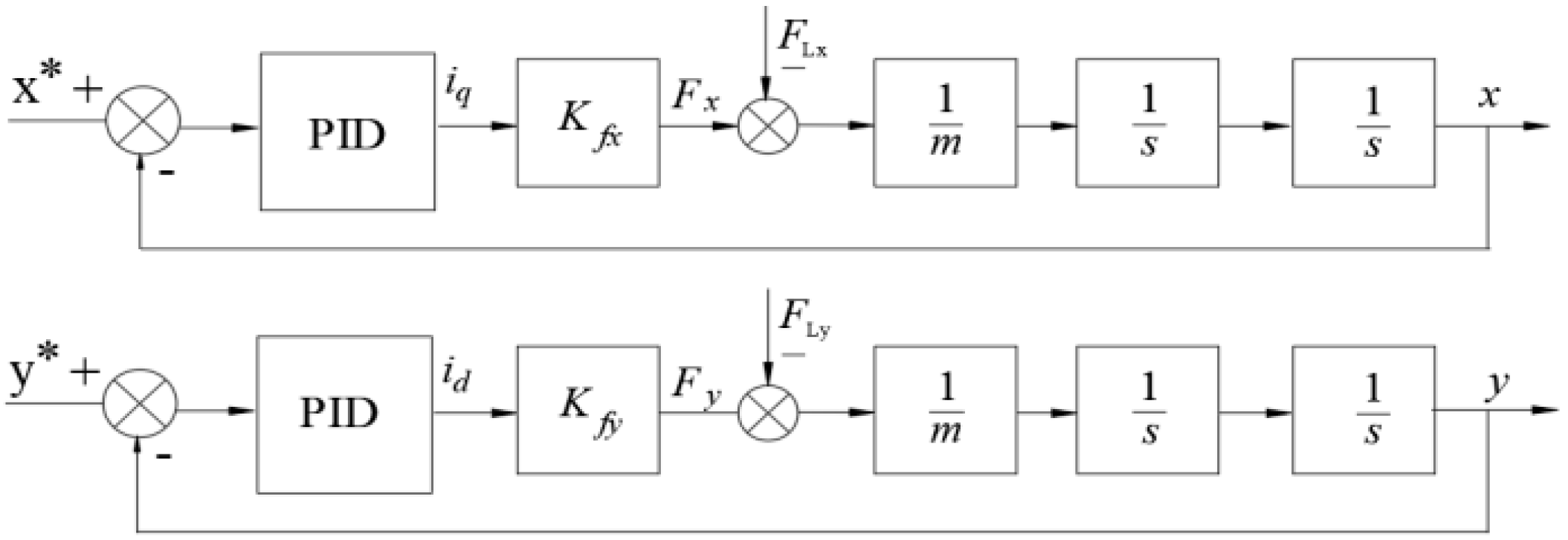
From Equations (33)–(35), the transfer function models can be set up as shown in Figure 11 and Figure 12.
(a) Designing Position Controller
From the model in Figure 11, setting:
K f = K f x m = K f y m
The PID controller transfer function is expressed as:
k P ( 1 + 1 T I s + T D s )
Then, the transfer function of close-loop is:
G k ( s ) = R ( s ) S ( s ) 1 + R ( s ) S ( s ) = K f k P T D T I s 2 + K f k P T I s + K f k P T I s 3 + K f k P T D T I s 2 + K f k P T I s + K f k P = B ( s ) A ( s )
The system becomes stable only when all the constant coefficients of the polynomial function have the same sign, that is, they satisfy the condition:
{ T I > 0 , K f k P T D > 0 , K f k P > 0 K f k P T I T D > 1
To determine the PID parameters, the pole-placement method will be used. The order of polynomial function is 3, so the poles should be chosen as s 1 = s 2 = s 3 = s 0 . Then, the polynomial function becomes:
( s + s 0 ) 3 = s 3 + 3 s 0 s 2 + 3 s 0 2 s + s 0 3
From Equations (38) and (40), we have:
A ( s ) = s 3 + K f k P T D s 2 + K f k P s + K f k P T I
Hence, the PID parameters are calculated as:
k P = 3 s 0 2 K f , T I = 3 s 0 , T D = 1 s 0
where:
s 0 > 0 , s 0 R
The condition in Equation (43) determines the stability of the system, so the greater the value of s 0 , the smaller the stability time and the better the quality of the system. However, the system needs to be provided with an extremely large energy. In fact, it is necessary to choose the optimal poles that suit the limit energy source. Meaning that the pole can only be selected for a finite value.
(b) Designing Speed Controller
From the models in Figure 11, setting:
K T ω = K T J
Similar to the position controller, the pole-placement method is also used to determine the PI parameters. The PI controller transfer function is expressed as:
k P ω ( 1 + 1 T I ω s )
Then, the transfer function of close-loop is:
G k ( s ) = R ( s ) S ( s ) 1 + R ( s ) S ( s ) = K T ω k P ω T I ω s + K T ω k P ω T I s 2 + K T ω k P ω T I ω s + K T ω k P ω = B ( s ) A ( s )
The polynomial function has the form:
( s + s 0 ω ) 2 = s 2 + 2 s 0 ω s + s 0 ω 2
From Equations (46) and (47), we have:
A ( s ) = T I s 2 + K T ω k P ω T I ω s + K T ω k P ω
The PI parameters are calculated as:
k P ω = 2 s 0 ω K T ω , T I ω = 2 s 0 ω
Similar to the position control design, it is important to choose s 0 ω which is suitable for the limit energy source and working ability of the system.

3. Simulation and Experimental Results

3.1. Control Hardware

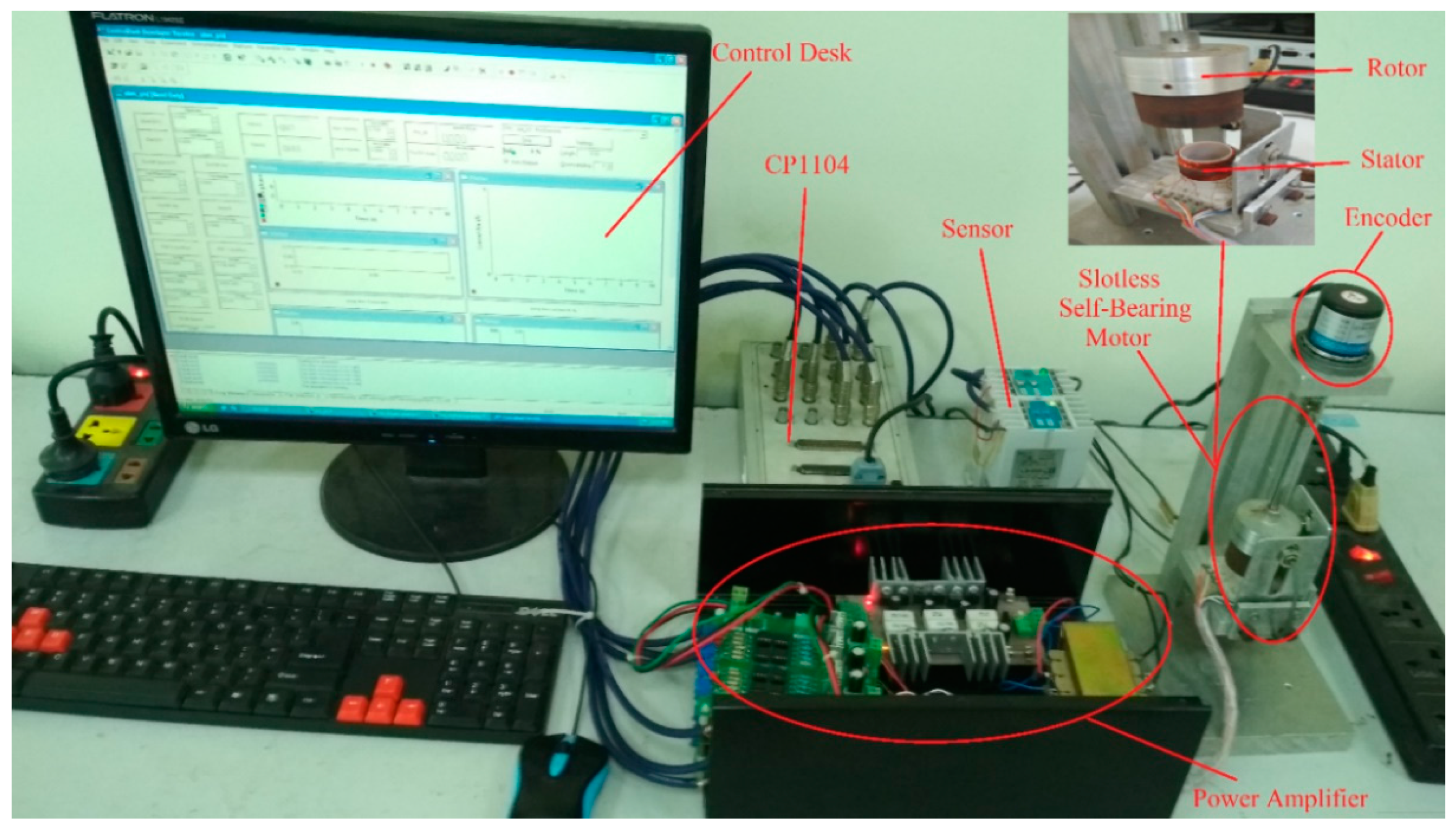
To confirm the abovementioned control method, an experimental system was set up, as shown in Figure 13. It included a PC, a dSPACE DS1104 board, a Sentec’s displacement sensor, a power amplifier and a slotless self-bearing motor attached to a rotary encoder (Figure 13). In this paper, only rotational motion along the z-axis and the horizontal translations along x and y axes of the rotor were considered; that is, the axial translation along z axis was mechanically constrained. The permanent magnet of the rotor had a diameter of 22 mm. The magnetic flux density was sinusoidal, and its maximum amplitude was approximately 0.59 T. The copper wire had a diameter of 27 mm and the number of turns was 55. The length of the parallel part lp was 8 mm and the length of the serial part was 6 mm, respectively.
The control system used a dSPACE DS1104 board dedicated to the control of electrical drives. It included pulse width modulation (PWM) units, general purpose input/output units (eight analog-to-digital converters (ADC) and eight digital-to-analog converters (DAC)), and an encoder interface. The DS1104 read the displacement signals from the displacement sensors via the ADC, and the rotor angle position and speed from the encoder via an encoder interface. The DS1104 calculated the stator reference currents and sent its commands to the power amplifier through a DAC. The current source amplifier was used to supply the stator current. When the starting current was limited to 1 A, for the speed control, the pole value s 0 ω = 5 was chosen and the controllers’ coefficients were: k P ω = 0.0228 , T I ω = 0.4 and for position control the PID controllers’ coefficients were k P = 1167 , T I = 0.0857 , T D = 0.0268 when the pole value s 0 = 35 was chosen.

3.2. Simulation Results

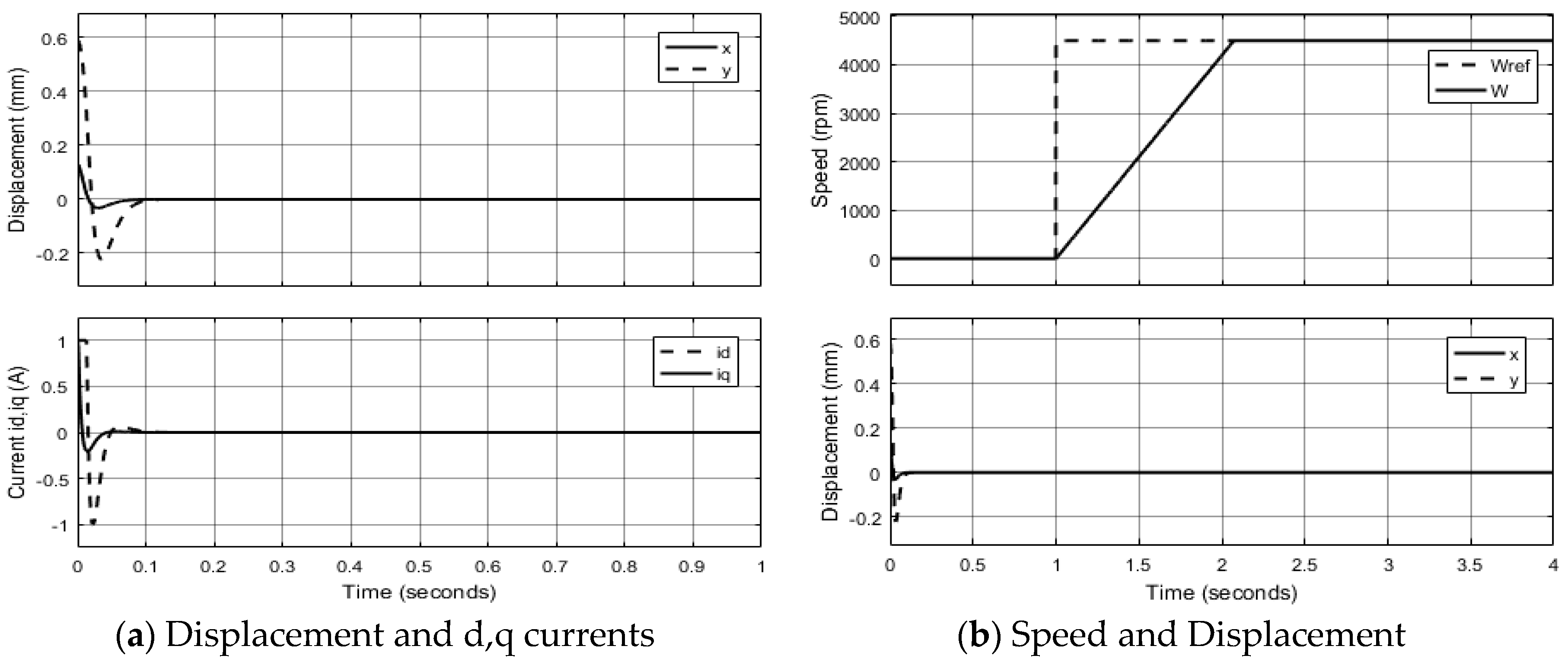
In order to confirm the proposed control method, the simulation model of the SSBM drives was implemented on Matlab/Simulink. Figure 14a shows the radial displacements of the rotor in x,y directions and the currents i d , i q respectively when the motor has no load. The original displacement error was set up x = 0.13 mm and y = 0.59 mm, then when the position controller started to work, the displacements jumped to zero after about 0.1 s. Figure 14b illustrates the displacements and the speed under no-load conditions when the position controller was working. The rotor speed reached 4500 rpm after about 1.1 s and during the acceleration, therefore, there was no influence on the displacements.
Figure 15 shows the influence of the external impulse force when the motor is rotating. When the rotor speed was 4000 rpm, there were external impulse forces (Flx = 1 N, Fly = 0.3 N) acting on the rotor in the horizontal direction at the time of 3 s. At this time, displacement errors occurred, but quickly returned to zero and the rotor speed was not changed. Obviously, there was no influence between radial position and speed.
Figure 16 shows the change in the rotating speed and torque current (Am) at the start and reverse when the motor had load (Tl = 0.02 Nm). The starting current was limited to 1 A. The speed reached 2000 rpm after 0.9 s and the rotating direction was changed after about 1.4 s.

3.3. Experimental Results

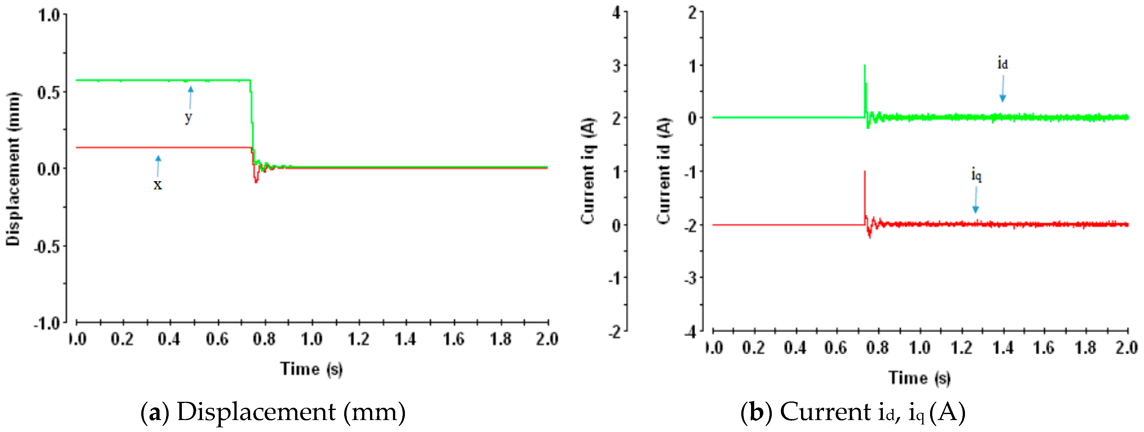
First, the position controller was tested. Figure 17a shows the displacement responses of the rotor while the motor speed was 0 rpm and Figure 17b shows the currents id, iq, respectively. The original displacement errors were set up x = 0.13 mm and y = 0.59 mm, then when the position controller started to work, the displacements jumped to zero after about 0.1 s. At this time, the shaft of the rotor aligned with the origin coordinates.
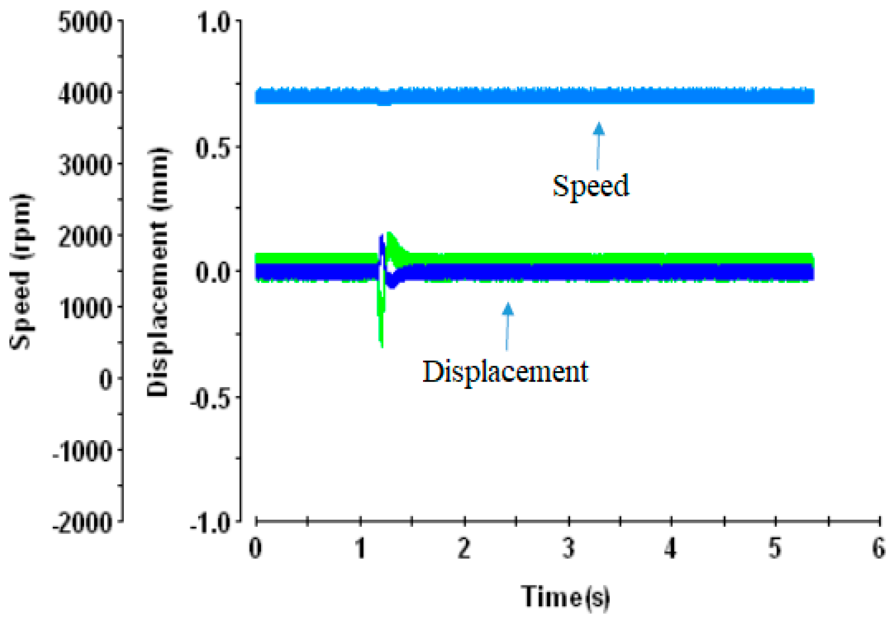
Figure 18a,b illustrate the displacements and the speed under no-load conditions when the position controller was working. The rotor speed reached 4500 rpm after about 1.8 s. At this speed range, the displacements were vibrated and the maximum error was about 0.2 mm. Figure 19 shows the influence of external impulse force when the motor was rotating. When the rotor speed was 4000 rpm, there was an external impulse force acting on the shaft of the rotor in the horizontal direction at the time of 1.2 s. Consequently, a displacement error occurres, but it quickly returned to zero and the rotor speed was not changed.
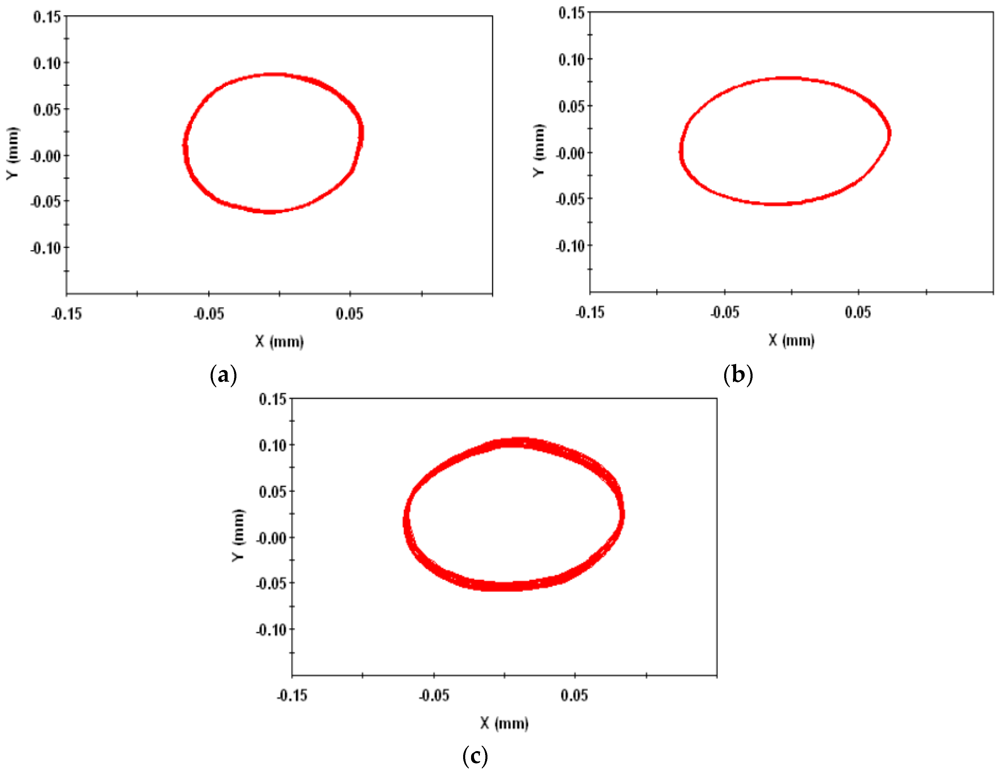
Figure 20 presents the trajectories of the rotor motion at 2000 rpm, 4000 rpm and 4500 rpm. In all cases, the maximum amplitude of vibration was about 0.1 mm, and the rotor rotated stably.
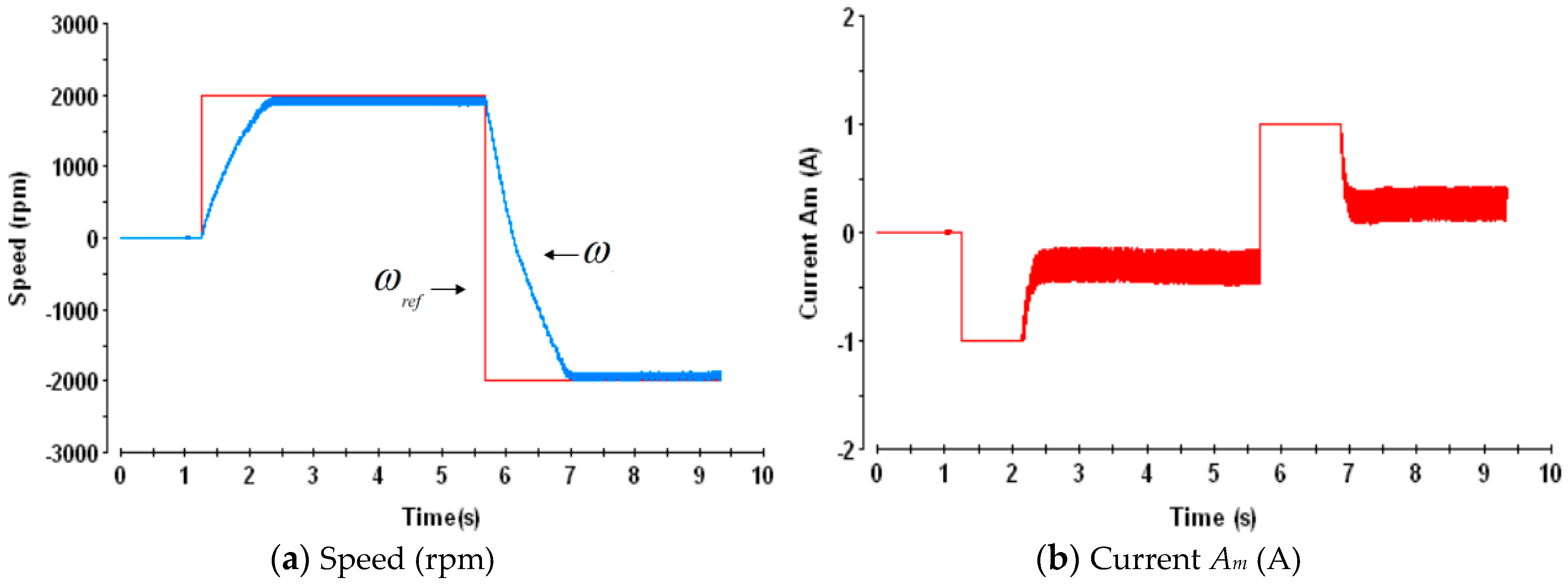
Next, the acceleration of speed was tested. Figure 21a shows the change in the rotating speed at the start and reverse when the motor had load. Figure 21b describes the respective current Am. The starting current was limited to 1 A. The loaded speed reached 2000 rpm after 1 s and the rotating direction was changed after about 1.4 s.
The results confirm that the proposed control system for the SSBM has the capability to control both the radial position and the rotor speed using PID and PI controller, and that the SSBM works stably in modes such as start, reverse, rotation load and external radial pulse forces.

4. Conclusions

The SSBM is a potential product for the specialized motor manufacturing industry, which requires high performance, large power density and simple structures. This paper analyzed the operating principle and the calculation method of torque and bearing forces for the SSBM. In addition, the analysis and design of controllers for rotating speed and radial position were also presented in more detail. The experimental results showed that the rotating speed and rotor position are controllable and the SSBM could operate stably using the proposed control method.

Author Contributions

Conceptualization, S.U.; Investigation, H.P.N., X.B.N. and T.T.B.; Methodology, Q.D.N.; Project administration, Q.D.N.; Writing—original draft, H.P.N.; Writing—review & editing, Q.D.N.

Funding

This research was funded by Ministry of Science and Technology of Vietnam, grant number ĐTĐLCN.44/16.

Conflicts of Interest

The authors declare no conflict of interest.

Nomenclature

SymbolUnitDescription
ψ RadThe angular position of the rotor
θ RadThe angular around origin coordinate
θ 0 RadThe angular position of the +a-phase winding
τ NmThe total torque of the motor
F + a f , F + d f , F a f , F d f NThe amplitude of bearing force of +a, +d, −a, −d phase
F + a T , F + d T , F a T , F d T NThe amplitude of torque force of +a, +d, −a, −d phase
Fa, Fb, FcNThe total forces acting on the rotor by two symmetrical phases a and d, b and e, c and f, respective
i a f , i b f , i c f AThe bearing currents of a-phase, b-phase and c-phase
i d , i q AThe amplitude of direct axis bearing current and the quadrate axis bearing current
i a T , i b T , i c T AThe torque currents of a-phase, b-phase and c-phase
A m AThe amplitude of the torque current
τ a , τ b , τ c NmThe total torque generated by two symmetrical phases a and d, b and e, c and f, respective
ϕ m RadThe phase of the torque current
l p , l t mThe parallel component and the serial component of the winding
k m , k n m current-torque coefficients
k b , k n b current-force coefficients
MKgWeight of the rotor
RmThe radius of the rotor
rmThe radius of the winding
am/s2The acceleration of the rotor
Fx, FyNBearing forces on the x-axis and y-axis
Fl, Flx, FlyNLoad Forces
TlNmLoad Torque
k P ω , T I ω PI controllers’ coefficients
k P , T I , T D PID controllers’ coefficients
s 0 Pole point of the position controller
s 0 ω Pole point of the speed controller

References

  1. Okada, Y.; Dejima, K.; Ohishi, T. Analysis and comparison of PM synchronous motor and induction motor type magnetic bearing. IEEE Trans. Ind. Appl. 1995, 32, 1047–1053. [Google Scholar] [CrossRef]
  2. Ren, Z.; Stephens, L.S. Closed-loop performance of a six degree-of freedom precision magnetic actuator. IEEE/ASME Trans. Mechatron. 2005, 10, 666–674. [Google Scholar] [CrossRef]
  3. Schneider, T.; Binder, A. Design and evaluation of a 60.000 rpm permanent magnet bearingless high speed motor. In Proceedings of the 7th International Conference on Power Electronics and Drive Systems 2007, Bangkok, Thailand, 27–30 November 2007; pp. 1–8. [Google Scholar]
  4. Nguyen, Q.D.; Ueno, S. Analysis and Control of Non-Salient Permanent Magnet Axial-Gap Self-Bearing Motor. IEEE Trans. Ind. Electron. 2011, 58, 2644–2652. [Google Scholar] [CrossRef]
  5. Nguyen, Q.D.; Ueno, S. Modeling and Control of Salient-Pole Permanent Magnet Axial Gap Self-Bearing Motor. IEEE/ASME Trans. Mechatron. 2011, 16, 518–526. [Google Scholar] [CrossRef]
  6. Ueno, S.; Iseki, R.; Jiang, C. Stability of a tilt-controlling axial gap self-bearing motor with single-stator. Mech. Eng. J. 2017, 4, 1–12. [Google Scholar] [CrossRef]
  7. Qu, R.; Aydin, M.; Lipo, T.A. Performance comparison of dual-rotor radial-flux and axial-flux permanent-magnet BLDC machines. In Proceedings of the IEEE International Electric Machines and Drives Conference, Madison, WI, USA, 1–4 June 2003. [Google Scholar]
  8. Salazar, A.O. A review of developments in bearingless motors. In Proceedings of the 7th International Symposium on Magnetic Bearings, Zurich, Switzerland, 23–25 August 2000; pp. 335–340. [Google Scholar]
  9. Yajima, S.; Takemoto, M.; Tanaka, Y.; Chiba, A.; Fukao, T. Total Efficiency of a Deeply Buried Permanent Magnet Type Bearingless Motor Equipped with 2-pole Motor Windings and 4-pole Suspension Windings. In Proceedings of the IEEE Power Engineering Society 2007 General Meeting, Tampa, FL, USA, 24–28 June 2007. [Google Scholar]
  10. Grabner, H.; Amrhein, W.; Silber, S.; Gruber, W. Nonlinear feedback control of a bearingless brushless DC motor. IEEE/ASME Trans. Mechatron. 2010, 15, 40–47. [Google Scholar] [CrossRef]
  11. Steinert, D.; Nussbaumer, T.; Kolar, J.W. Slotless Bearingless Disk Drive for High-Speed and High-Purity Applications. IEEE Trans. Ind. Electron. 2014, 61, 5974–5986. [Google Scholar] [CrossRef]
  12. Steinert, D.; Nussbaumer, T.; Kolar, J.W. Evaluation of One- and Two-Pole-Pair Slotless Bearingless Motors with Toroidal Windings. IEEE Trans. Ind. Appl. 2016, 52, 172–180. [Google Scholar] [CrossRef]
  13. Karnavas, Y.L.; Chasiotis, I.D. PMDC coreless micro-motor parameters estimation through Grey Wolf Optimizer. In Proceedings of the XXII International Conference on Electrical Machines (ICEM) 2016, Lausanne, Switzerland, 4–7 September 2016; pp. 865–870. [Google Scholar]
  14. Stamenkovic, I.; Milivojevic, N.; Schofield, N.; Krishnamurthy, M.; Emadi, A. Design Analysis and Optimization of Ironless Stator Permanent Magnet Machines. IEEE Trans. Power Electron. 2013, 28, 2527–2538. [Google Scholar] [CrossRef]
  15. Ueno, S.; Uematsu, S.I.; Kato, T. Development of a Lorentz-Force-Type Slotless Self-Bearing Motor. J. Syst. Design Dyn. 2009, 3, 462–470. [Google Scholar] [CrossRef] [Green Version]
  16. Ueno, S.; Kato, T. A Novel Design of a Lorentz-Force-Type Small Self Bearing Motor. In Proceedings of the 8th International Conference on Power Electronics and Drive Systems, Taipei, Taiwan, 2–5 Novemer 2009; pp. 926–931. [Google Scholar]
  17. Kobayashi, S.; Ooshima, S.K.M.; Uddin, M.N. A Radial Position Control Method of Bearingless Motor Based on d-q Axis Current Control. IEEE Trans. Ind. Appl. 2013, 49, 1827–1835. [Google Scholar] [CrossRef]
  18. Ooshima, M.; Kobayashi, S.; Uddin, M.N. Magnetic levitation tests of a bearingless motor based on d-q axis current control. In Proceedings of the 2012 IEEE Industry Applications Society Annual Meeting, Las Vegas, NV, USA, 7–11 October 2012. [Google Scholar]
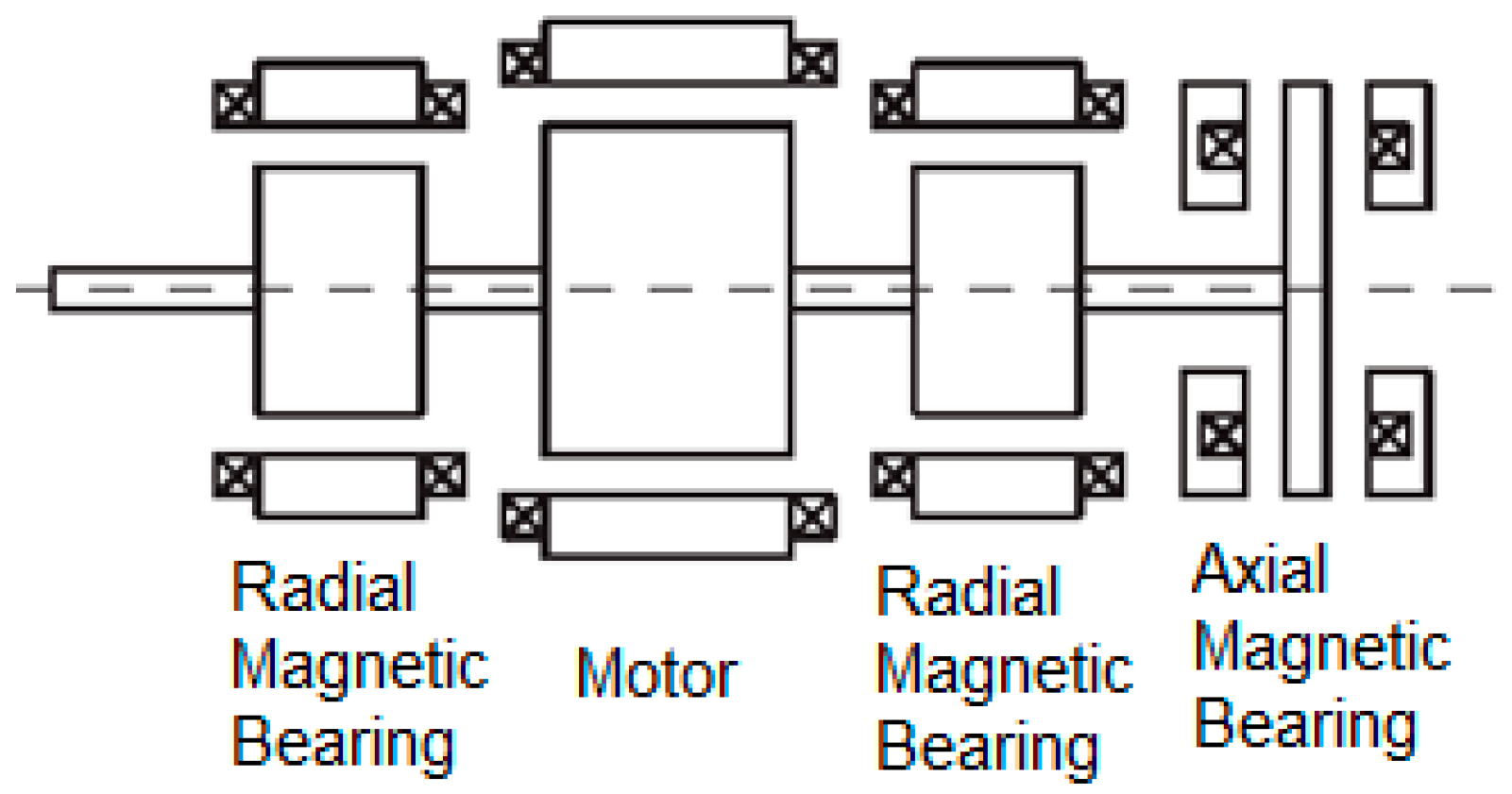
Figure 1. Structure of conventional magnetic bearing motor.
Actuators 08 00057 g001
Figure 2. Structure of axial combined magnetic bearing motor.
Actuators 08 00057 g002
Figure 3. Structure of radial combined magnetic bearing motor.
Actuators 08 00057 g003
Figure 4. Structure of the slotless self-bearing motor.
Actuators 08 00057 g004
Figure 5. Generation of bearing force and rotating torque.
Actuators 08 00057 g005
Figure 6. Coordinate axis.
Actuators 08 00057 g006
Figure 7. Bearing force.
Actuators 08 00057 g007
Figure 8. Motor torque.
Actuators 08 00057 g008
Figure 9. The diagram of a wire loop.
Actuators 08 00057 g009
Figure 10. Control Structure of the slotless self-bearing motor (SSBM).
Actuators 08 00057 g010
Figure 11. The position controller transfer function model.
Actuators 08 00057 g011
Figure 12. The speed controller transfer function model.
Actuators 08 00057 g012
Figure 13. Experimental system.
Actuators 08 00057 g013
Figure 14. Responses of displacement, currents and speed when the motor has no load.
Actuators 08 00057 g014
Figure 15. Influence of external impulse force.
Actuators 08 00057 g015
Figure 16. Speed and current when the motor has load.
Actuators 08 00057 g016
Figure 17. Responses of displacement and bearing currents at zero speed.
Actuators 08 00057 g017
Figure 18. Response of displacement and speed at start without load.
Actuators 08 00057 g018
Figure 19. Influence of external impulse force.
Actuators 08 00057 g019
Figure 20. Orbit of rotor at (a) 2000 rmp, (b) 4000 rmp and (c) 4500 rpm
Actuators 08 00057 g020
Figure 21. Speed and current when the rotating direction is changed with load.
Actuators 08 00057 g021