Design and Analysis of a Clutched Parallel Elastic Actuator

 , , ,
, , ,  and
and
Abstract
:1. Introduction
2. Mechanical Design
2.1. Technical Requirements
2.2. Structure Designed
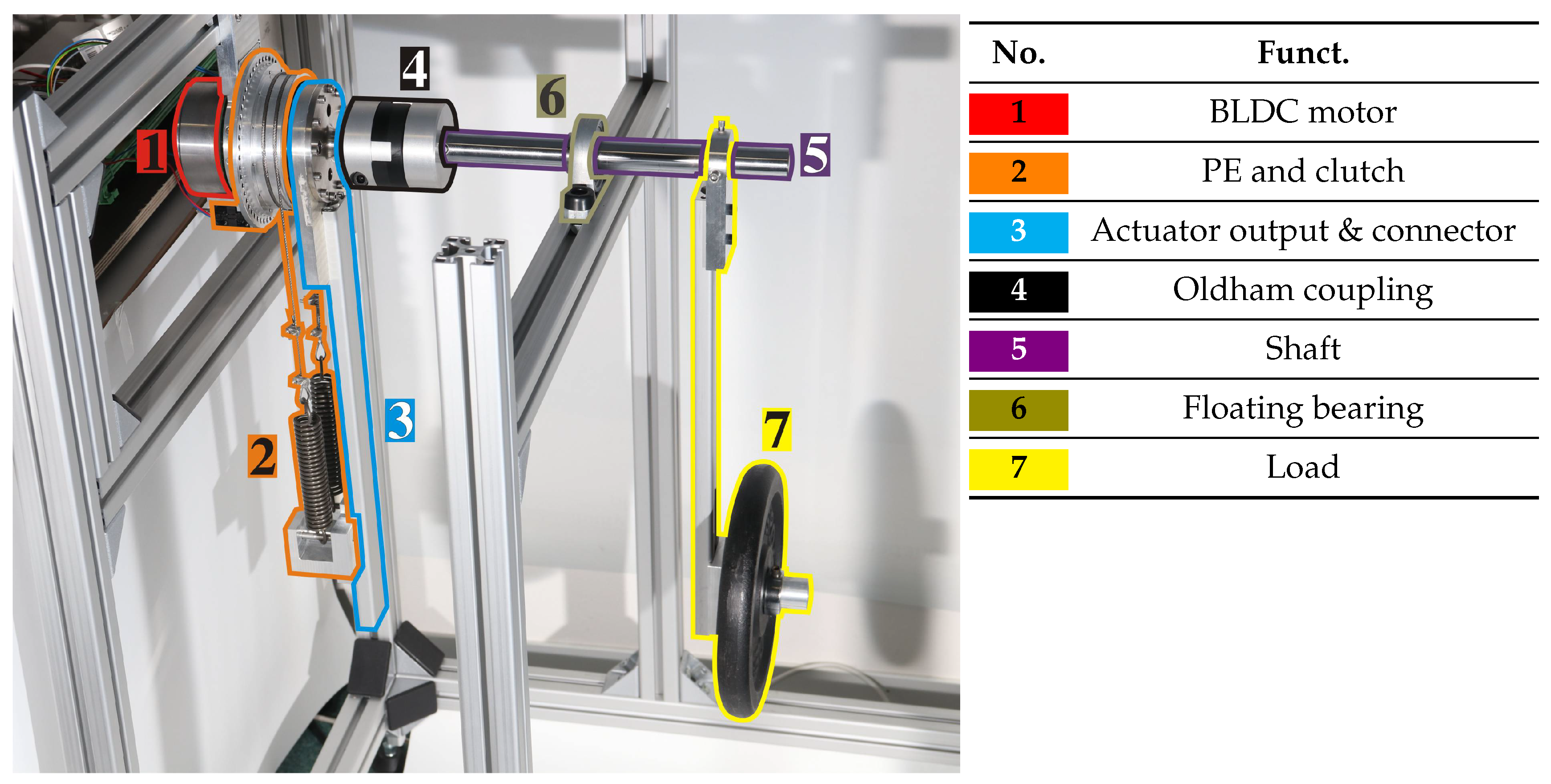
2.3. Prototype
3. Modeling and Control
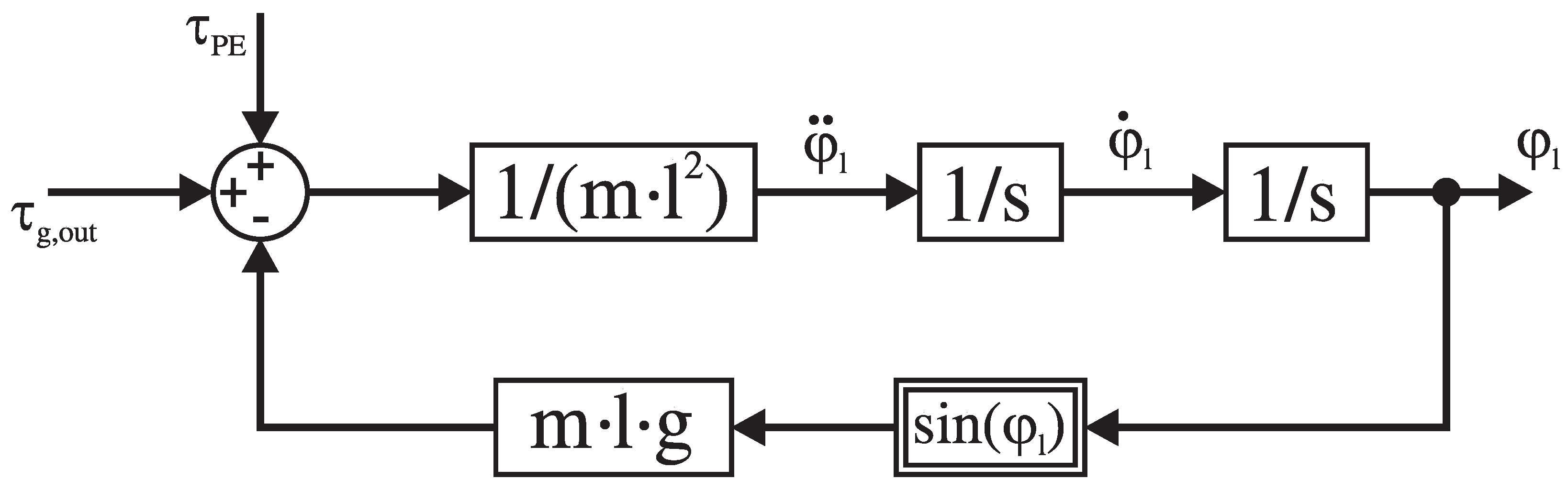
3.1. Modeling
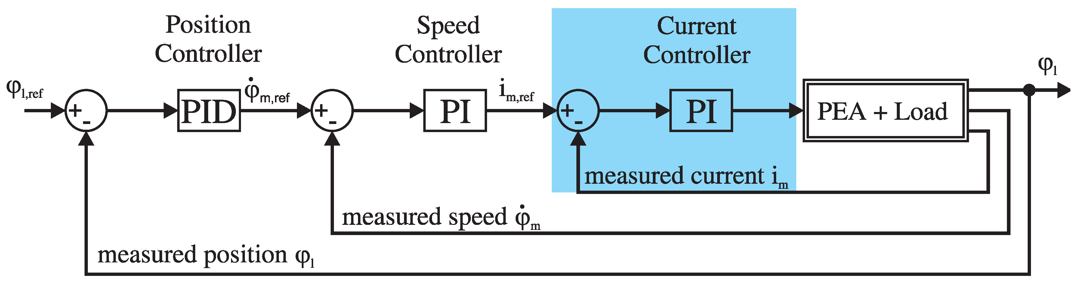
3.2. Cascaded Control
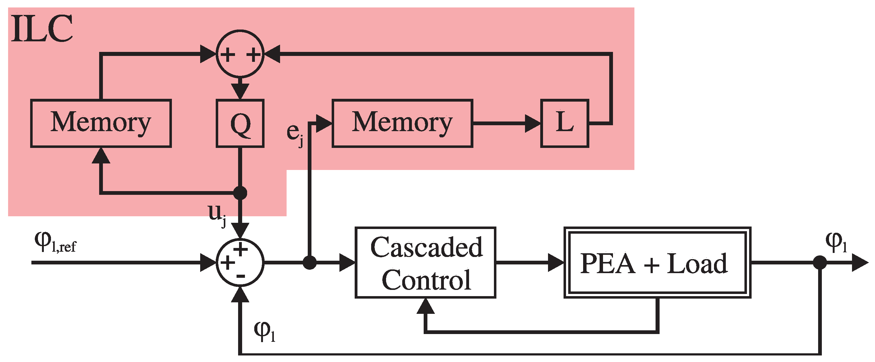
3.3. Iterative Learning Control
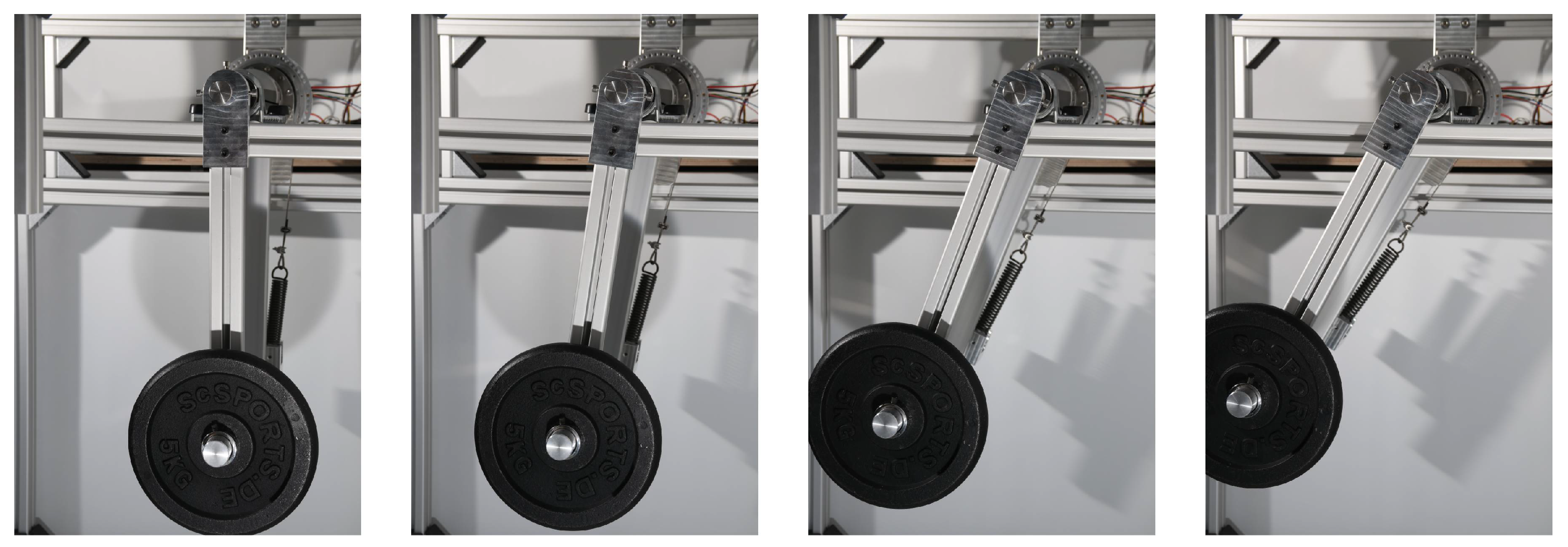
4. Experiments
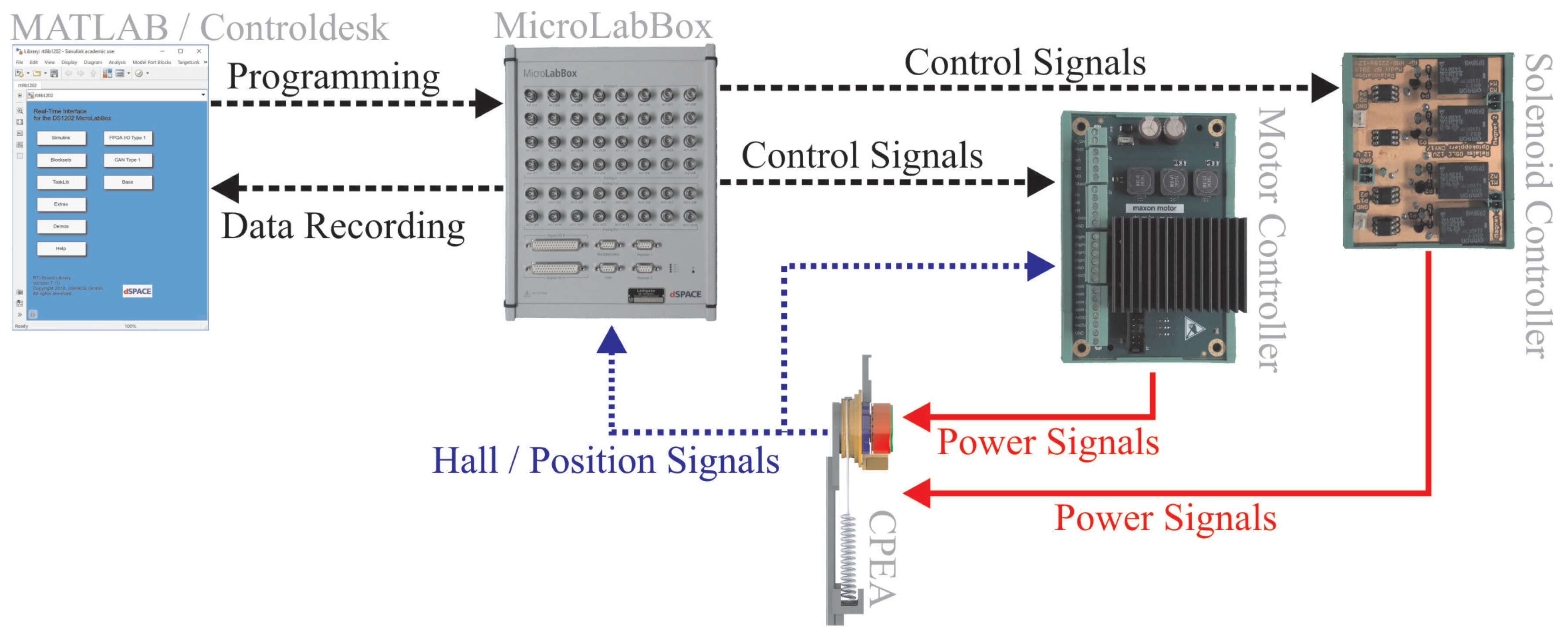
Experimental Setup
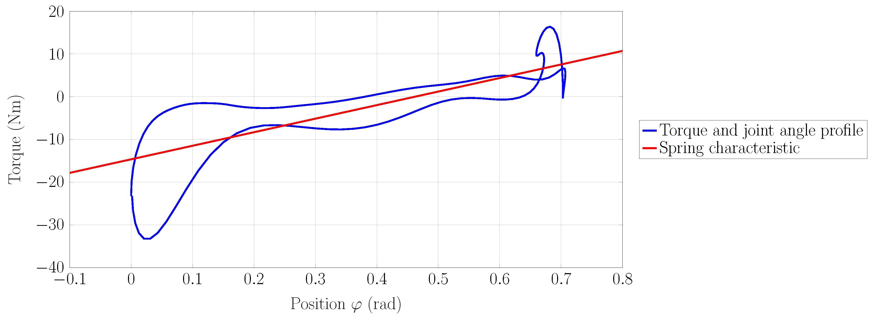
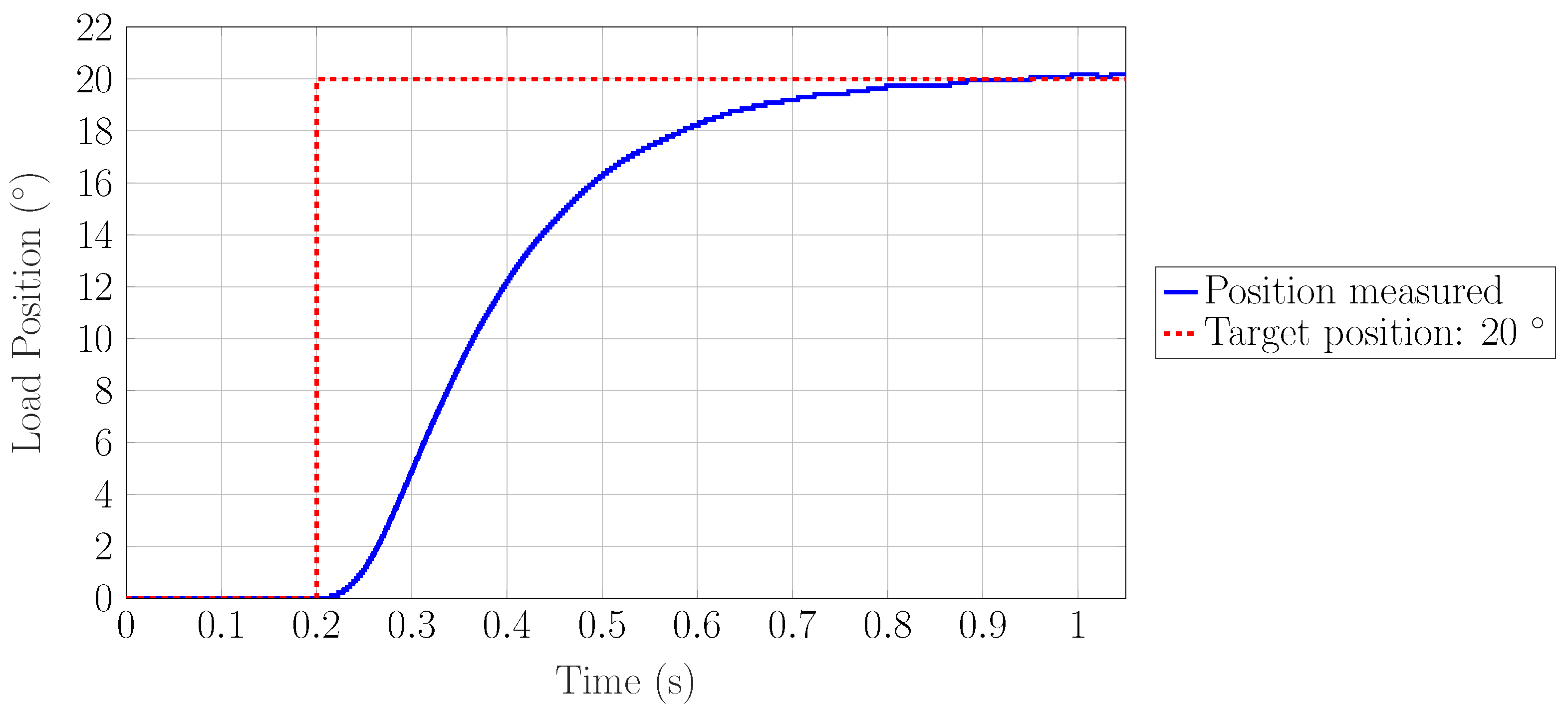
5. Results and Discussion
6. Conclusions
Author Contributions
Funding
Conflicts of Interest
Abbreviations
| BLDC | Brushless Direct Current |
| CPEA | Clutched Parallel Elastic Actuator |
| ILC | Iterative Learning Control |
| MACCEPA | Mechanically-Adjustable Compliance and Controllable Equilibrium Position Actuator |
| MLB | MicroLabBox |
| PE | Parallel Elasticity |
| PEA | Parallel Elastic Actuator |
| PI Controller | Proportional-Integral Controller |
| PID Controller | Proportional-Integral-Derivative Controller |
| RA | Rigid Actuator |
| RMS | Root Mean Square |
| SEA | Series Elastic Actuator |
| cRSEA | Clutched Rigid Series Elastic Actuator |
References
- Ham, R.V.; Sugar, T.G.; Vanderborght, B.; Hollander, K.W.; Lefeber, D. Compliant actuator designs. IEEE Robot. Autom. Mag. 2009, 16, 81–94. [Google Scholar] [CrossRef]
- Maciejasz, P.; Eschweiler, J.; Gerlach-Hahn, K.; Jansen-Troy, A.; Leonhardt, S. A survey on robotic devices for upper limb rehabilitation. J. Neuroeng. Rehabil. 2014, 11, 3. [Google Scholar] [CrossRef] [PubMed]
- Jafari, A.; Tsagarakis, N.G.; Vanderborght, B.; Caldwell, D.G. A novel actuator with adjustable stiffness (AwAS). In Proceedings of the IEEE/RSJ International Conference on Intelligent Robots and Systems, Taipei, Taiwan, 18–22 October 2010; pp. 4201–4206. [Google Scholar]
- Plooij, M.; Wolfslag, W.; Wisse, M. Clutched elastic actuators. IEEE-ASME Trans. Mech. 2017, 22, 739–750. [Google Scholar] [CrossRef]
- Plooij, M.; van Nunspeet, M.; Wisse, M.; Vallery, H. Design and evaluation of the Bi-directional Clutched Parallel Elastic Actuator (BIC-PEA). In Proceedings of the IEEE International Conference on Robotics and Automation (ICRA), Washington State Convention Centre, Seattle, WA, USA, 25–30 May 2015; pp. 1002–1009. [Google Scholar]
- Stuhlenmiller, F.; Schuy, J.; Beckerle, P.; Rinderknecht, S. A user-specific human-machine interaction strategy for a prosthetic shank adapter. Curr. Dir. Biomed. Eng. 2017, 3, 493–496. [Google Scholar] [CrossRef] [Green Version]
- Grimmer, M.; Eslamy, M.; Gliech, S.; Seyfarth, A. A comparison of parallel-and series elastic elements in an actuator for mimicking human ankle joint in walking and running. In Proceedings of the 2012 IEEE International Conference on Robotics and Automation, Saint Paul, MN, USA, 14–18 May 2012; pp. 2463–2470. [Google Scholar]
- Roozing, W.; Li Medrano-Cerda, Z.; Gustavo, A.; Caldwell, D.; Tsagarakis, N. Development and control of a compliant asymmetric antagonistic actuator for energy efficient mobility. IEEE-ASME Trans. Mech. 2015, 21, 1080–1091. [Google Scholar] [CrossRef]
- Liu, X.; Rossi, A.; Poulakakis, I. A Switchable Parallel Elastic Actuator and its Application to Leg Design for Running Robots. IEEE-ASME Trans. Mech. 2018, 23, 2681–2692. [Google Scholar] [CrossRef]
- Masood, J.; Ortiz, J.; Fernández, J.; Mateos, L.; Caldwell, D. Mechanical design and analysis of light weight hip joint parallel elastic actuator for industrial exoskeleton. In Proceedings of the 2016 6th IEEE International Conference on Biomedical Robotics and Biomechatronics (BioRob), Singapore, 26–29 June 2016; pp. 631–636. [Google Scholar]
- Wang, S.; Van Dijk, W.; Van der Kooij, H. Spring uses in exoskeleton actuation design. In Proceedings of the 2011 IEEE International Conference on Rehabilitation Robotics (ICORR), Zurich, Switzerland, 29 June–1 July 2011; pp. 1–6. [Google Scholar]
- Mettin, U.; La Hera, P.; Freidovich, L.; Shiriaev, A. Parallel elastic actuators as a control tool for preplanned trajectories of underactuated mechanical systems. Int. J. Robot. Res. 2010, 29, 1186–1198. [Google Scholar] [CrossRef]
- Li, Y.; Li, Z.; Penzlin, B.; Tang, Z.; Liu, Y.; Guan, X.; Ji, L.; Leonhardt, S. Design of the Clutched Variable Parallel Elastic Actuator (CVPEA) for lower Limb Exoskeletons. In Proceedings of the 41st International Conference of the IEEE Engineering in Medicine and Biology Society (EMBC), Berlin, Germany, 23–27 July 2019. accepted. [Google Scholar]
- Häufle, D.; Taylor, M.D.; Schmitt, S.; Geyer, H. A clutched parallel elastic actuator concept: Towards energy efficient powered legs in prosthetics and robotics. In Proceedings of the 4th IEEE RAS & EMBS International Conference on Biomedical Robotics and Biomechatronics (BioRob), Rome, Italy, 24–27 June 2012. [Google Scholar]
- Cestari, M.; Sanz-Merodio, D.; Arevalo, J.; Garcia, E. An adjustable compliant joint for lower-limb exoskeletons. IEEE-ASME Trans. Mech. 2015, 20, 889–898. [Google Scholar] [CrossRef]
- Lewis, C.; Sahrmann, S. Effect of posture on hip angles and moments during gait. Man. Ther. 2015, 20, 176–182. [Google Scholar] [CrossRef] [PubMed]
- Toxiri, S.; Calanca, A.; Ortiz, J.; Fiorini, P.; Caldwell, D.G. A parallel-elastic actuator for a torque-controlled back-support exoskeleton. IEEE Robot. Autom. Lett. 2017, 3, 492–499. [Google Scholar] [CrossRef]
- Brackx, B.; Geeroms, J.; Vantilt, J.; Grosu, V.; Junius, K.; Cuypers, H.; Vanderborght, B.; Lefeber, D. Design of a modular add-on compliant actuator to convert an orthosis into an assistive exoskeleton. In Proceedings of the 5th IEEE RAS/EMBS International Conference on Biomedical Robotics and Biomechatronics, Sao Paulo, Brazil, 12–15 August 2014; pp. 485–490. [Google Scholar]
- Zhang, T.; Tran, M.; Huang, H. Design and experimental verification of hip exoskeleton with balance capacities for walking assistance. IEEE-ASME Trans. Mech. 2018, 23, 274–285. [Google Scholar] [CrossRef]
- Woo, H.; Na, B.; Kong, K. Design of a compact rotary series elastic actuator for improved actuation transparency and mechanical safety. In Proceedings of the 2017 IEEE International Conference on Robotics and Automation (ICRA), Singapore, 29 May–3 June 2017; pp. 1872–1877. [Google Scholar]
- Önen, Ü.; Botsalı, F.; Kalyoncu, M.; Tınkır, M.; Yılmaz, N.; Şahin, Y. Design and actuator selection of a lower extremity exoskeleton. IEEE-ASME Trans. Mech. 2013, 19, 623–632. [Google Scholar] [CrossRef]
- Neuhaus, P.D.; Noorden, J.H.; Craig, T.J.; Torres, T.; Kirschbaum, J.; Pratt, J.E. Design and evaluation of Mina: A robotic orthosis for paraplegics. In Proceedings of the 2011 IEEE International Conference on Rehabilitation Robotics, Zurich, Switzerland, 29 June–1 July 2011; pp. 1–8. [Google Scholar]
- Lee, S.; Sankai, Y. Power assist control for leg with hal-3 based on virtual torque and impedance adjustment. In Proceedings of the IEEE International Conference on Systems, Man and Cybernetics, Yasmine Hammamet, Tunisia, 6–9 October 2002. [Google Scholar]
- Perry, J.; Burnfield, J. Gait Analysis-Normal and Pathological Function; Slack Inc.: Thorofare, NJ, USA, 2010; pp. 176–182. [Google Scholar]
- De Leva, P. Adjustments to Zatsiorsky-Seluyanov’s segment inertia parameters. J. Biomech. 1996, 29, 1223–1230. [Google Scholar] [CrossRef]
- Vallery, H.; Veneman, J.; Van Asseldonk, E.; Ekkelenkamp, R.; Buss, M.; Van Der Kooij, H. Compliant actuation of rehabilitation robots. IEEE Robot. Autom. Mag. 2008, 15, 60–69. [Google Scholar] [CrossRef] [Green Version]
- Harmonic Drive AG. Projektierungsanleitung Units HFUS-2UH/2SO/2SH; Harmonic Drive AG: Limburg an der Lahn, Germany, 2014. [Google Scholar]
- Nahrstaedt, H.; Schauer, T.; Hesse, S.; Raisch, J. Iterative Learning Control of a Gait Neuroprosthesis. Automatisierungstechnik 2008, 56, 494–501. [Google Scholar] [CrossRef]
- Bristow, D.; Tharayil, M.; Alleyne, A. A survey of iterative learning control. IEEE Control. Syst. Mag. 2006, 26, 96–114. [Google Scholar]
- Yang, H.; Li, S. PD-Type ILC Algorithm Research with Forgetting Factor for a Class of Linear Systems with Multiple Time Delays. Appl. Mech. Mater. 2012, 220, 1125–1130. [Google Scholar] [CrossRef]
- Rouse, E.J.; Gregg, R.D.; Hargrove, L.J.; Sensinger, J.W. The difference between stiffness and quasi-stiffness in the context of biomechanical modeling. IEEE Trans. Biomed. Eng. 2012, 60, 562–568. [Google Scholar] [CrossRef] [PubMed]


| Topology | Power | Rated Torque | Velocity | Spring Rate | Purpose | Ref. |
|---|---|---|---|---|---|---|
| PEA | 100 W | 28.9 Nm | 37.4 rpm | 8 Nm/rad | Industrial | [17] |
| MACCEPA | 50 W | 11.2 Nm * | 28 rpm | 28.1 to 81.4 Nm/rad | Sit-to-stand | [18] |
| SEA | 90 W | 40 Nm | 25 rpm | 123 Nm/rad | Walking | [19] |
| cRSEA | 200 W | 18.2 Nm | 84.7 rpm | Energy buffer/torque sensor | Walking | [20] |
| RA | 100 W | 34 Nm | 25 rpm | Not applicable | Walking | [21] |
| RA | 355 W | 40.5 Nm | 75 rpm | 24 kNm/rad | Walking (0.2 m/s) | [22] |
| RA | 150 W | 68.6 Nm | 36.3 rpm | Not applicable | Walking | [23] |
| Specifications | Value |
|---|---|
| Nominal torque | 49.4 Nm (active only) |
| Nominal speed | 3.7 rad/s |
| No load speed | 4.4 rad/s |
| Rated motor power | 260 W (Maxon EC 90) |
| Mass | 3.1 kg (including 30 Nm/rad springs) |
| Axial length | 105 mm (including leg adapter) |
| Spring rate | 10–67 Nm/rad (Mass: 50–360 g) |
| Spring type | Steel tension springs (EN 10270-1) |
| Clutch actuator | Bistable solenoid (30 W) |
| Name | Symbol | Value |
|---|---|---|
| Rotor inertia | 5.300 · 10 kg·m | |
| Torque constant | 0.136 Nm/A | |
| Speed constant | 7.35 rad/Vs | |
| Motor resistance | 0.29 | |
| Motor inductance | 0.369 H | |
| Damping constant (motor) | d | 1.5 Nm/rad |
| Spring rate (PE) | 30 Nm/rad | |
| Equilibrium position | 0.35 rad | |
| Nominal torque (gearbox) | 25 Nm | |
| Gearbox inertia | 1.93 kg· m | |
| Reduction ratio | 50:1 | |
| Coefficients (torque efficiency) | 1.019 | |
| −0.00765 | ||
| −0.849 | ||
| 1.758 | ||
| Coefficients (speed efficiency) | 0.8776 | |
| −0.0008136 s/rad | ||
| s/rad | ||
| s/rad | ||
| Load inertia | 0.8 kg· m | |
| Gravitational constant | g | 9.81 m/s |
| Mass of the load | m | 5 kg |
| Number i | 0 | 1 | 2 | 3 | 4 | 5 | 6 |
|---|---|---|---|---|---|---|---|
| Frequency | shift | Hz | Hz | Hz | Hz | Hz | Hz |
| Magnitude | |||||||
| Phase shift |
| Iteration | 1 | 2 | 3 | 4 | 5 | 6 | 7 |
|---|---|---|---|---|---|---|---|
| RMSE |
© 2019 by the authors. Licensee MDPI, Basel, Switzerland. This article is an open access article distributed under the terms and conditions of the Creative Commons Attribution (CC BY) license (http://creativecommons.org/licenses/by/4.0/).
Share and Cite
Penzlin, B.; Enes Fincan, M.; Li, Y.; Ji, L.; Leonhardt, S.; Ngo, C. Design and Analysis of a Clutched Parallel Elastic Actuator. Actuators 2019, 8, 67. https://doi.org/10.3390/act8030067
Penzlin B, Enes Fincan M, Li Y, Ji L, Leonhardt S, Ngo C. Design and Analysis of a Clutched Parallel Elastic Actuator. Actuators. 2019; 8(3):67. https://doi.org/10.3390/act8030067
Chicago/Turabian StylePenzlin, Bernhard, Mustafa Enes Fincan, Yinbo Li, Linhong Ji, Steffen Leonhardt, and Chuong Ngo. 2019. "Design and Analysis of a Clutched Parallel Elastic Actuator" Actuators 8, no. 3: 67. https://doi.org/10.3390/act8030067
APA StylePenzlin, B., Enes Fincan, M., Li, Y., Ji, L., Leonhardt, S., & Ngo, C. (2019). Design and Analysis of a Clutched Parallel Elastic Actuator. Actuators, 8(3), 67. https://doi.org/10.3390/act8030067