Article

Sensorless Driving/Braking Control for Electric Vehicles

1
Bioinformatic Computing and Control Laboratory, Department of Electrical Engineering, National Chung Hsing University, Taichung 407, Taiwan
2
School of Automation Science and Electrical Engineering, Beihang University, Beijing 100191, China
*
Author to whom correspondence should be addressed.
Actuators 2020, 9(1), 22; https://doi.org/10.3390/act9010022
Submission received: 24 February 2020 / Revised: 16 March 2020 / Accepted: 19 March 2020 / Published: 22 March 2020

Abstract

:
A sensorless driving/braking control system for electric vehicles is explained in the present paper. In the proposed system, a field-oriented control (FOC) was used to integrate driving and braking controls in a unified module for reducing the cost of hardware and simultaneously incorporating functional flexibility. An antilock braking system can swiftly halt a vehicle during emergency braking. An electromagnetic reverse braking scheme that provided retarding torque to a running wheel was developed. The scheme could switch the state of the MOSFETs used in the system by alternating the duty cycle of pulse width modulation to adjust the braking current generated by the back electromotive force (EMF) of the motor. In addition, because the braking energy required for the electromagnetic braking scheme is related only to the back EMF, the vehicle operator can control the braking force and safely stop an electric vehicle at high speeds. The proposed integrated sensorless driving and electromagnetic braking system was verified experimentally.

1. Introduction

In the early 1970s, nonlinear time-varying characteristics of alternating current (AC) motor drives were used for vector control. The electromagnetic torque generated by a motor is proportional to the driving current. Many researchers have studied sensorless control approaches as an alternative for mechanical sensors to reduce cost. Field-oriented control (FOC) is rapidly becoming popular in motor drives [1,2]. However, most of the current sensorless FOC techniques are limited to the individual motor driving or braking technology [1,3,4,5]. Integrated driving and braking control design (i.e., driving and braking control units sharing the same hardware) has not been studied previously.
With the increasing use of green energy for ensuring environmental protection, electric vehicles (EVs) are one of the most promising technologies that can transform the transportation system. Typically, mechanical braking mechanisms are used in current EVs. Riding down steep hills on electric bikes with mechanical brakes is dangerous because the brakes are likely to fail due to overheating of the disc or drum brake. Braking under critical conditions, such as on wet or slippery road surfaces or in certain emergency situations caused by mistakes committed by the riders, can result in the driver losing control of the vehicle.
To resolve the aforementioned problems, an integrated driving and braking control design based on sensorless FOC technology and incorporating an antilock braking system (ABS) was proposed. The proposed system includes the following three aspects:
(i)
For motor driver design, the FOC algorithm was used on the AN1078 microchip, by Microchip Technology Co., Arizona [4], which can perform satisfactorily even when no position sensors are attached to the motor shaft. Low-inductance shunt resistors were used in three-phase inverters to measure the motor current.
(ii)
Braking techniques—such as short-circuit [6], regenerative [7,8,9], kinetic [10], super-capacitor [11], and slip control-based braking [12]—regenerative braking are currently used. However, the braking effect decreases considerably when the battery is fully charged. In addition, the low conversion efficiency generally results in unsatisfactory braking performance. Therefore, an electromagnetic braking system was proposed in this research. Back electromotive force (back EMF) generated by the motor was used in the proposed braking system. The braking effect can be enhanced by intermittently reversing the direction of the magnetic field force from driving to braking using a permanent magnet synchronous motor (PMSM) stator coil. To achieve this enhanced braking, the relationship between the rotor angle and brake signal was determined according to a specific function. Combining this function with the aforementioned FOC-based driving mechanism, we can adjust the braking effect according to the parameters of a proportional integral controller. An ultracapacitor was added in the braking loop to boost instantaneous braking energy.
(iii)
For effective ABS realization, we first estimated the slip ratio, because determining the precise speed of electric bikes during movement in sensorless motors is difficult. According to studies [13,14,15], the sliding mode and current controls can be used to maintain the slip ratio within the optimal range for ensuring adhesion to the road. Underwater robots have been used in applications such as ocean development, ocean investigations, military operations, and marine environment protection. High-performance autonomous underwater vehicles are required for various applications, such as military defense and marine protection, especially for propulsion and maneuverability.
It is noted that all variables appeared in the following development, unless specified otherwise, are all defined in the continuous-time domain of t.

2. Model

Neglecting the vortex and magnetic hysteresis losses, the mathematical model of PMSM is presented in the matrix form as
[ V A Q V B Q V C Q ] = R s I 3 [ i a i b i c ] + [ L s M M M L s M M M L s ] d d t [ i a i b i c ] + [ e a e b e c ]
where v a , v b , and are the phase voltages; i a , i b , and i c are the phase currents; R s is the resistance; L s is the phase inductance; M is the mutual inductance; e a , e b , and e c are the phase electromotive forces; and I 3 is the 3 × 3 identity matrix. The mathematical model is applicable to brushed DC motors, brushless DC motors, and AC induction motors.

2.1. Principle of FOC

The methodology is briefly summarized [16,17]. A proportional integral (PI) controller is used to achieve the desired system response in a closed-control loop. The derivative gain is not used because of the slow response time due to changes in the motor speed.
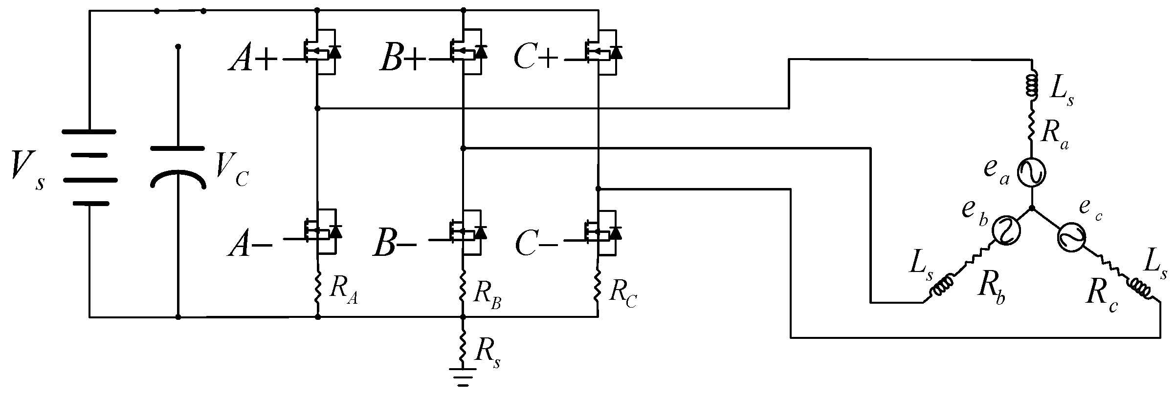
Space vector pulse-width modulation (SVPWM) is a novel method to drive a permanent magnet synchronous motor [4,18], and it is used to supply the AC motor with the desired phase voltage. Figure 1 illustrates the typical three-phase power inverter, where A + , A , B + , B , C + , and C denote semiconductor switches that can be either power MOSFETs or IGBTs.
In space vector modulation (SVM), the voltage vector of motors is controlled to generate minimum harmonic distortion of the currents to ensure the torque ripple is small.
We define eight vectors, namely V 0 { 0 , 0 , 0 } , V 1 { 1 , 0 , 0 } , V 2 { 1 , 1 , 0 } , V 3 { 0 , 1 , 0 } , V 4 { 0 , 1 , 1 } , V 5 { 0 , 0 , 1 } , V 6 { 1 , 0 , 1 } , and V 7 { 1 , 1 , 1 } . Here, V 0 and V 7 are zero vectors. The vector distribution map [19,20] was composed of two adjacent vectors that were divided into six regions.
The equation of V r e f using the volt-second balance rule is expressed as
V r e f T s = V 1 T 1 + V 2 T 2 + V 0 T 0
where T 1 , T 2 , and T 0 satisying T s = i = 0 2 T i with T s denoting the sampling period of V r e f , are the sampling periods of V 1 , V 2 , and V 0 (or V 7 ), respectively. From the simple voltage divider rule, we obtain | V 1 | = | V 2 | = 2 V D C / 3 . We can easily obtain the sampling periods of and as [21]
T 1 = 3 T s V r e f V D C sin ( π 3 ϕ ) , T 2 = 3 T s V r e f V D C sin ( ϕ ) .
The order of vector combination between two adjacent vectors with zero vectors depending on each sector is listed in Table 1.

2.2. Sensorless Driver Design

A crucial step in sensorless FOC-based driver design is to construct an estimator to obtain the rotor position. We adopt the current observer, back-EMF estimator, and speed calculator to constitute the system model as those proposed in [4]. Figure 2 illustrates the overall block diagram of the estimator.
The mathematical model of the depicted motor is expressed as
V s = R s I s + L s d d t I s + e s
where I s = i a + i b + i c is the motor current vector, V s = V A Q + V B Q + V C Q is the input voltage vector, e s = e a + e b + e c is the back-EMF vector, R s is the winding resistor, and L s is the winding inductance. Translating (5) to the discrete-time domain gives
I s ( i + 1 ) = ( 1 T z R s L s ) I s ( i ) + T z L s [ V s ( i ) e s ( i ) ]
where T z is the control period and i is the sampling cycle.
Sliding mode control (SMC) [14,20,22] can be used to effectively control an uncertain nonlinear plant. Because an error exists between the real and estimated currents, here, the SMC was used to eliminate the error. The output of the SMC was used as a correction factor denoted by z.
In the motor model, the input voltage Vs was assumed to be the actual motor input voltage. The unknown variable is the back EMF. Thus, the difference z between the actual current I s and the estimated current I s * refers to the value of the back EMF. In Figure 2, e = I s I s * with e max denoting the maximum allowable error. The computed sign of the error e is multiplied by a SMC gain denoted K. Because the use of a sliding mode controller causes the estimated current to produce a sawtooth wave, the estimated back EMF e s * can be obtained by passing the correction factor z as the input to the low-pass filter as
e ( i ) = e ( i 1 ) + 2 π f c f p w m [ z ( i ) e ( i ) ]
where, in this research, f p w m = 15 kHz is set to be the PWM frequency and f c = 8.3 kHz is the cut-off frequency of the filter.
The estimated back EMF e s * was used to update the current back-EMF value. Then, the sawtooth wave of the estimated back-EMF e s * was filtered by another first-order LPF yielding e s * * . At this time, the signal of the secondary-filtered back-EMF e s * * is smoothed. Here, e α * * and e β * * are the vector components of e s * * . The Cordic algorithm was then applied to estimate the transformed angle θ of e α * * and e β * * .
Because of the filtering function applied during the calculation of angle θ, we performed phase compensation before using the calculated angle to energize the motor windings. The formula used for the calculation of the speed can be expressed as [4]
ω = i = 1 m ( θ ( i ) θ ( i 1 ) ) K s p e e d
where ω is angular velocity of the motor, Kspeed is the amplification factor for the desired speed range which, and m is required number of accumulated θ. To ensure the signal of the speed calculation is smooth, a first-order low-pass filter was applied for compensating the motor speed ω to obtain the filtered value in ω*. Here, the gain K s p e e d was tuned by verifying the measured ground truth of the motor rotating speed ω via a taco meter and the accumulated value of θ for the number of m.
FOC is not effective when a motor stops rotation. Therefore, a minimum speed is commonly required to obtain the estimated back EMF for calculating the rotor angle. We allowed the motor to spin at a fixed angular acceleration rate in the open-loop control initially and then switched to closed-loop control after the motor was stable. Only at this stage can the motor speed be controlled by changing Id and Iq.

3. Integrated Driving/Braking Control

The novel integrated control system consists of three components, namely the current control circuit, speed control circuit, and SVPWM control loop.

3.1. Structure of the Driver

The architecture of the motor driver is briefly described. The braking system had the same framework but a different control logic. The driver was realized by a three-phase inverter with six power MOSFETs. Considering the necessity of the sensorless FOC algorithm, the driving part of the presented integrated system can be updated, as depicted in Figure 3, which depicts the circuit diagram of the driving mode. A switching device was used to switch between driving and braking.
Corresponding to the definition of SVM, six basic voltage vectors (not zeros) in the driving mode construct six current conduction loops with the direction of magnetic field force of the PMSM stator coils.

3.2. FOC-Based Braking Control Design

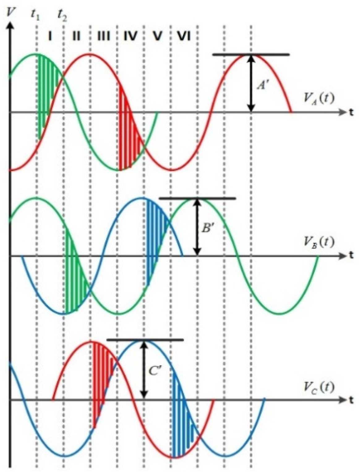
The three-phase back EMF of a PMSM denoted by V A , V B , and V C are defined as
V A = A sin ( t 1 6 π ) ,   V B = B sin ( t 9 6 π ) ,   V C = C sin ( t 5 6 π )
where A′, B′, and C′ denote amplitudes in the respective phases. Because T = 2π and the time period, for example, t2t1, the integral phase-to-phase back-EMF difference used as the braking power is expressed as
1 T t 1 t 2 ( V A V B ) I d t
This is illustrated in Figure 4.
In the braking system, the back EMF is used to generate braking torque by directing the braking current flow in the power MOSFETs in an efficient manner. To develop the maximal braking capability, the back EMF generated by the motor should be used in a short period of time. This is achieved by controlling the current I with the formula
F = I × B
where F is the electromagnetic force and B is the magnetic field.
In the braking control unit, various pulse width modulation (PWM)-controlled duty cycles are used in the electromagnetic braking system to achieve flexible adjustment of the braking current. Combining the braking control unit with the slip ratio control, we can achieve anti-lock braking system (ABS) without using the hydraulic power required in traditional mechanical ABS.
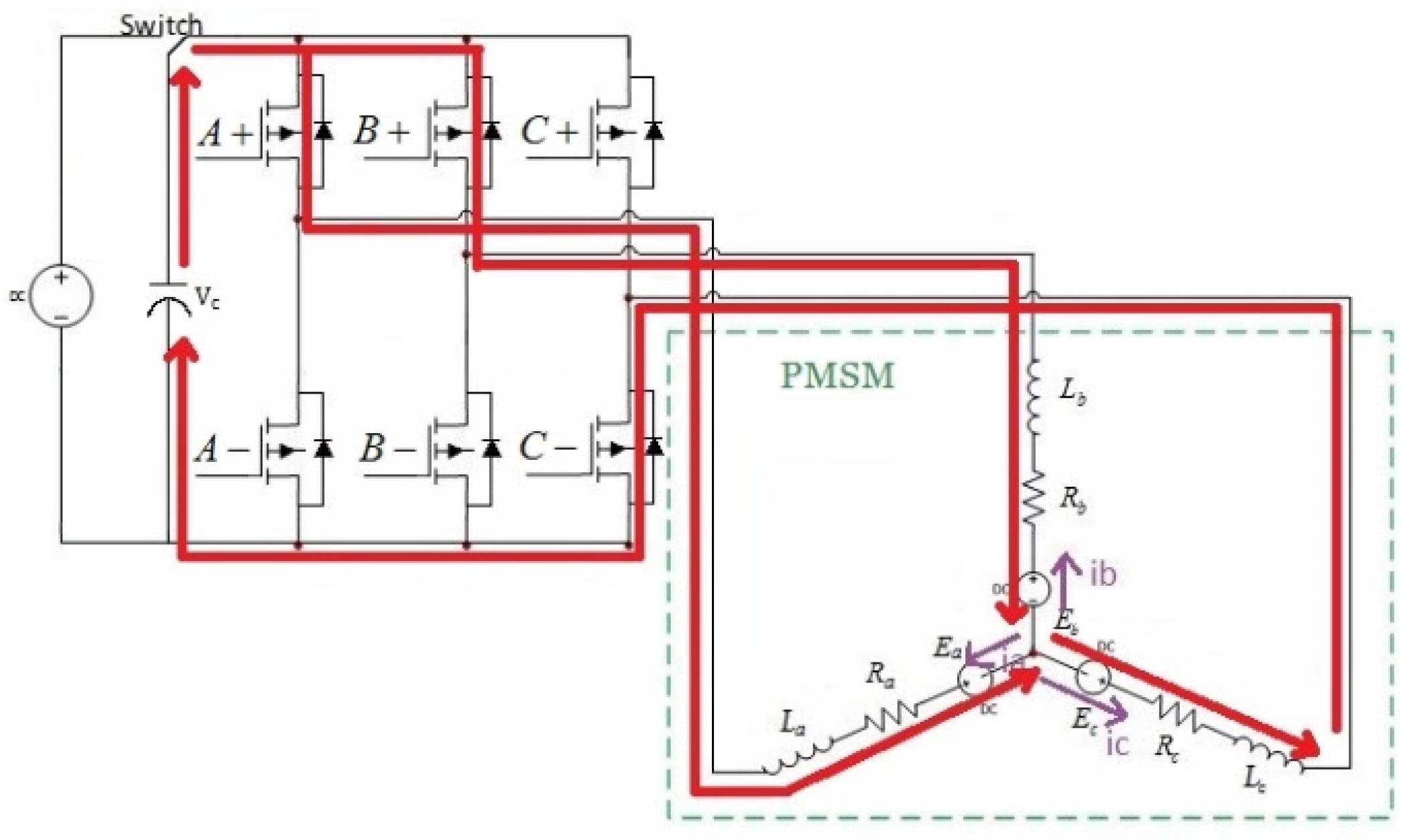
Figure 5 illustrates the equivalent circuit diagram of the braking mode. The virtual load in the braking circuit was an ultra-capacitor. The action time of the braking mode was extended by the capacitor because the capacitor discharged and instantaneous additional energy for braking assistance. This is closely related to the capacity of capacitor when the back EMF gradually decreases because of the decrease in the speed of the wheel. Therefore, six current conduction loops were constructed by six basic voltage vectors (not zeros). Only one of the six current conduction loops is depicted in Figure 6 to compare circuit diagram with that of the driving mode. In this case, the power metal-oxide-semiconductor field-effect transistors (MOSFETs) A+, B+, and C− were controlled during the ‘ON’ status.
Table 2 lists the control logic of six basic voltage vectors defined by SVM between the driving and braking modes. The table indicates when the motor enters the braking mode, the order of the voltage vectors was reversed, resulting in a rheostatic braking effect to the running wheel.
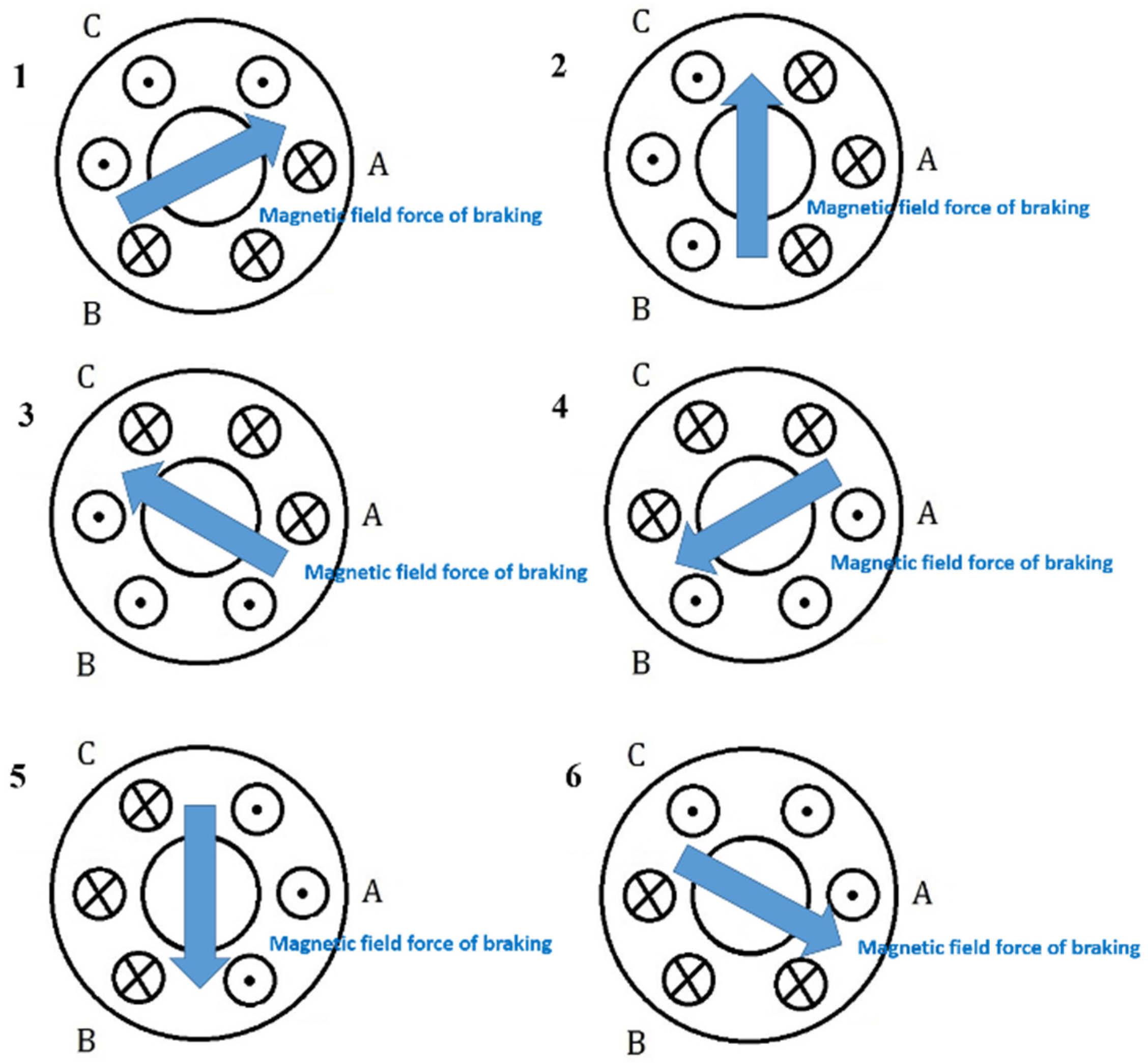
Referring to the braking status in Table 2, Figure 7 illustrates the schematic of the change in the direction of the magnetic field force of the stator coil for six basic voltage vectors defined by SVM in the brake mode.
We define the function as
θ = f ( S W , θ ) = { θ , S W = 1 θ , S W = 0
The proposed braking control system is activated on reaching the preset condition. The back EMF is stored in the ultracapacitor as additional energy for braking when the speed of the wheel is less.

3.3. Design of Anti-Lock Braking System

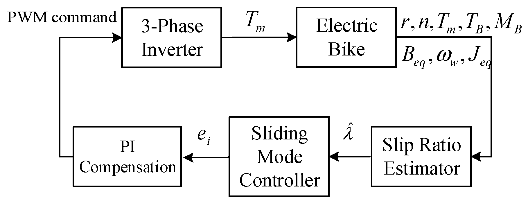
The ABS is used to keep the slip ratio within an ideal range for efficient braking by adjusting the duty cycle of PWM braking current. Although the accurate slip ratio is a key parameter in traditional ABSs of gas-powered vehicles, its use in electric bikes is not practical. A slip ratio estimator (SRE) that does not require vehicle speed measurement was introduced in the sensorless system. SMC was used for regulating the slip ratio to attain the optimal road adhesion and output to a PI current controller, the duty cycle of PWM was then determined according to the difference between the braking and reference currents. The overall braking control scheme is depicted in Figure 8.
The lateral friction force is not considered in ABS design. The electric bike automatically attains stability when the slip ratio for the maximum longitudinal friction force is considered because of the lateral friction force of the bike. We assumed that braking occurs only when the electric bike moves straight, driving resistance is ignored, and transmission ratio of the system is fixed.
The dynamic equations for the PMSM and the motion model of the driving wheel can be expressed as
J m ω ˙ m = T m B m ω m T L
where T m = K m i e , J w ω ˙ w = T w + T B B w ω w r F , M B V ˙ B = F , V w = ω w r , J m is the inertia of the motor, ω m is the angular speed of the motor, T m is the motor torque, B m is the damping coefficient of the motor, K m is the torque coefficient of the motor, i e is the phase current of the motor, T L is the torque generated because of the load, J w is the inertia of the rear wheel, ω w is the angular speed of the rear wheel, T w is the generated driving torque, T B is the braking torque, B w is the damping coefficient of the rear wheel, r is the radius of the rear wheel, F is the friction force, M B is the total mass of the electric bike, V B is the velocity of the bike, and V w is the tangent velocity of the rear wheel. In addition, for the fixed transmission ratio of the system, the following expression is used:
ω w = n ω m ,   T L = n T w
where n is the constant gear ratio. The equation of motion of the rear wheel speed can be further obtained as
J e q ω ˙ w = n T m + n 2 T B B e q ω w n 2 r F
where J e q = J m + n 2 J w and B e q = B m + n 2 B w . From Amontons’ first law, the friction force is expressed as
F = N μ ( λ ) = M B g μ ( λ )
where N is the normal force, g is the gravitational constant, μ is the friction coefficient, and λ is the slip ratio. When braking, λ is defined as
λ = 1 V w V B
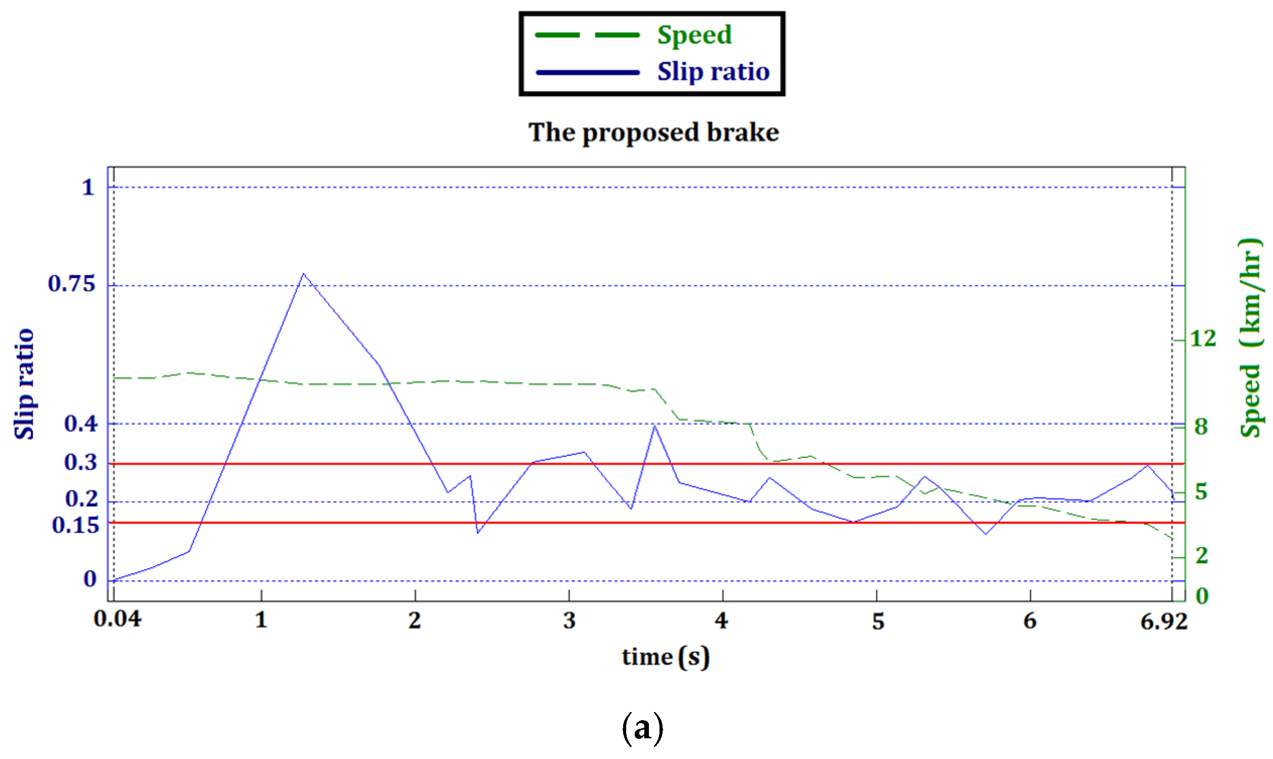
In general, the ideal slip ratio for the best tire-to-road adhesion is closely related to road surfaces and ranges from 0.15 to 0.3.

3.4. Design of Slip Ratio Estimator

Determining the precise speed of an electric bike in a sensorless system is typically difficult. Therefore, SRE method that does not require information about the vehicle velocity and acceleration was especially designed for the sensorless system [20].
Substituting (13)–(16) into (12), we obtain the following expression:
λ ˙ = ( n T m + n 2 T B B e q ω w J e q ω ˙ w n 2 r 2 M B ω w ) ( 1 λ ) 2 ω ˙ w ω w ( 1 λ )
where 1 λ = V w / V B and V ˙ w = ω ˙ w r = V w ω ˙ w / ω w . An SRE can be described as follows:
λ ^ ˙ = ( n T m + n 2 T B B e q ω w J e q ω ˙ w n 2 r 2 M B ω w ) ( 1 λ ^ ) 2 ω ˙ w ω w ( 1 λ ^ )
where λ ^ denotes the estimate of λ . The estimation error dynamics is expressed as follows:
e ˙ = [ ω ˙ w ω w n T m + n 2 T B J e q ω ˙ w B e q ω w n 2 r 2 M B ω w ( 2 λ λ ^ ) ] e
where e = λ λ ^ . Or equivalently,
e ˙ = 1 V w [ V ˙ w V ˙ B ( 2 λ λ ^ ) ] e
The condition of estimation error convergence is expressed as follows:
V ˙ w < V ˙ B ( 2 λ λ ^ )
During braking, V ˙ w 0 , V ˙ B 0 , and the wheel stops before the vehicle, that is, V ˙ w V ˙ B 0 . Moreover, λ is typically small, and the inequality is maintained for most practical applications.

3.5. Design of Slip Ratio Control

Next, we consider slip ratio control based on the slip ratio estimated by (19). The objective is to develop a controller such that the vehicle slip ratio tracks the ideal value under various road conditions [23] for the best tire-to-road adhesion.
To start, the first-order nonlinear time-varying system of (18) is expressed in the follows by excluding the brake control input u 1 ( t ) and using the estimated slip ratio as
λ ^ ˙ = f 1 ( λ ^ , t ) + b 1 ( λ ^ , t ) u 1 ( t )
where
f 1 ( λ ^ , t ) = n 2 T B B e q ω w J e q ω ˙ w n 2 r 2 M B ω w ( 1 λ ^ ) 2 ω ˙ w ω w ( 1 λ ^ ) ,   b 1 ( λ ^ , t ) = ( 1 λ ^ ) 2 n r 2 M B ω w
and the control input
u 1 = u c + u e q
where u c ( t ) provides compensation for the deviations from the sliding surface and the equivalent control causes the derivative of the sliding surface to stay on the sliding surface.
According to [24], the sliding surface can be selected as s ( λ ^ ) = λ ^ λ r e f where λ r e f is the ideal reference of λ . We assumed a positive definite Lyapunov function defined as
V ( λ ^ ) = 1 2 s 2 ( λ ^ )
Performing differentiation with respect to t results in the expression
V ˙ ( λ ^ ) = s ( λ ^ ) [ f 1 ( λ ^ , t ) + b 1 ( λ ^ , t ) u ( t ) ]
Therefore, choosing u ( t ) for a negative definite V ˙ ( λ ^ ) causes the trajectories to converge to the sliding surface. A typical choice of u c ( t ) is
u c ( t ) = U s g n ( s )
where U is the control gain. For the equivalent control, we use
u e q ( t ) = [ s ( λ ^ ) λ ^ b 1 ( λ ^ , t ) ] 1 s ( λ ^ ) λ ^ f 1 ( λ , t ) ,
or equivalently
u e q ( t ) = f 1 ( λ ^ , t ) b 1 ( λ ^ , t )
That is
s ˙ ( λ ^ ) = U s g n ( s ) ( 1 λ ^ ) 2 n r 2 M B ω w
therefore,
s ( λ ^ ) s ˙ ( λ ^ ) = U ( 1 λ ^ ) 2 n r 2 M B ω w | s |
The sliding condition s s ˙ η | s | is satisfied if the following condition is satisfied:
( 1 λ ^ ) 2 U n r 2 M B ω w η
where η is a positive constant that determines the convergence rate of λ ^ λ r e f , that is, the error between actual and ideal slip ratios for the best tire and road surface adhesion, to reach the sliding surface. Once η is determined, selection of the control gain U then considers satisfaction of the requirements of (29).
Finally, a PI compensation module was included to track the reference current computed according to the slip ratio SMC. The input to the module is e i = i r e f i f d b , where i r e f is the reference input and i f d b is the feedback braking current.
The design proposed here focuses only on the use of SMC combined with SRC to realize the function of ABS control for motor-driven vehicles. For the complete design ideas behind the ABS control one may refer to the excellent references, [23] and [25].

4. Experimental Implementation

4.1. Hardware Realization

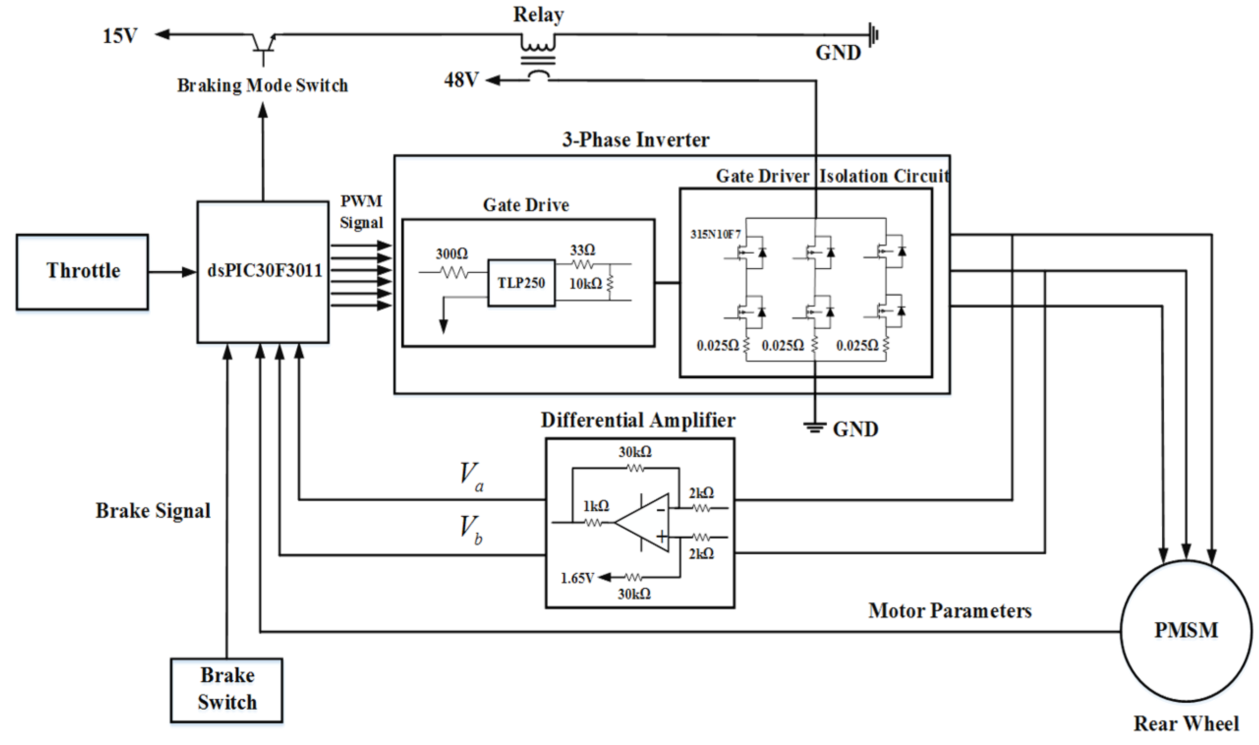
The electric bike was equipped with a permanent-magnet synchronous motor (PMSM), previously adopted in [24]. The dsPIC30F3011 microcontroller, by Microchip Technology Co., Arizona, US, was used to realize the integrated driving/braking control unit. The clock frequency of the controller was 40 MHz. Figure 9 illustrates the hardware architecture of the driving/braking system. The capacitance of the ultracapacitor (UC) used for boosting instantaneous braking current was 0.55 F.

4.2. Software Design

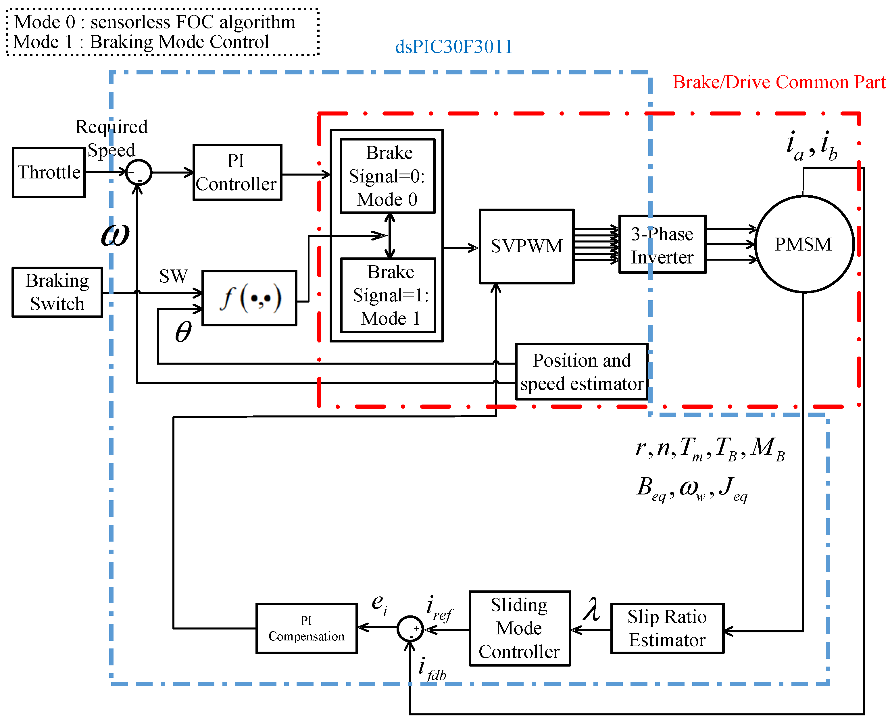
In the proposed system, an FOC-based sensorless driving component was combined with the electromagnetic braking system equipped with ABS control. The driving and the braking systems have the same hardware and functionally interact to form a simplified and low-cost architecture, as depicted in Figure 10.
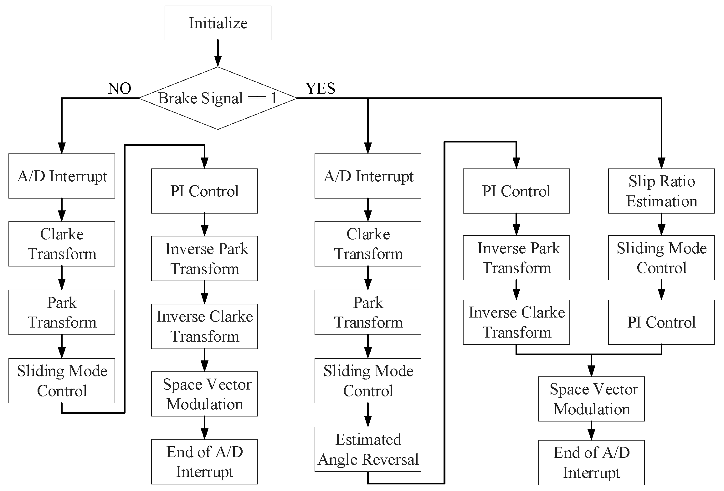
For the control strategy of the proposed system, we divided the driving unit into two parts, the FOC algorithm and the SRE for rotor position estimation, and speed of the motor for the sensorless system. Figure 11 depicts the operational flowchart of the control unit.

5. Experimental Results

5.1. Driver Implementation

The torque produced using the FOC algorithm for the PMSM was examined first. The maximum rotational speed of the electric motor was 400 rpm. Figure 12 depicts the output voltage of the space vector PWM (SVPWM) signal in region 4 of the vector distribution map. The controlled PWM output rapidly changed with the duty cycle at a PWM frequency of 15 kHz. The motor was switched to the closed-loop control after it attained stability. The phase current decreased at this stage and depended on the speed command.

5.2. Braking System Realization

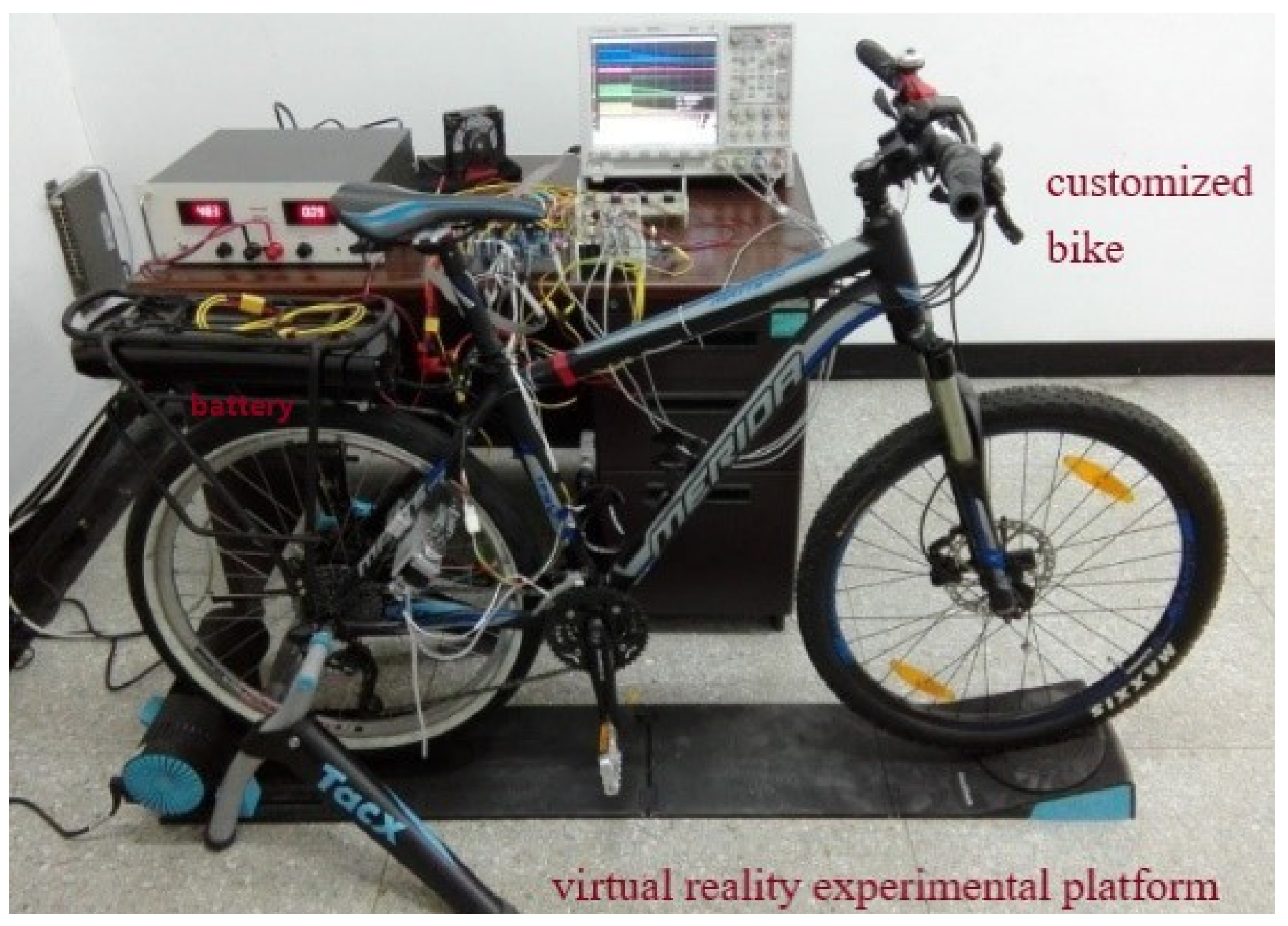
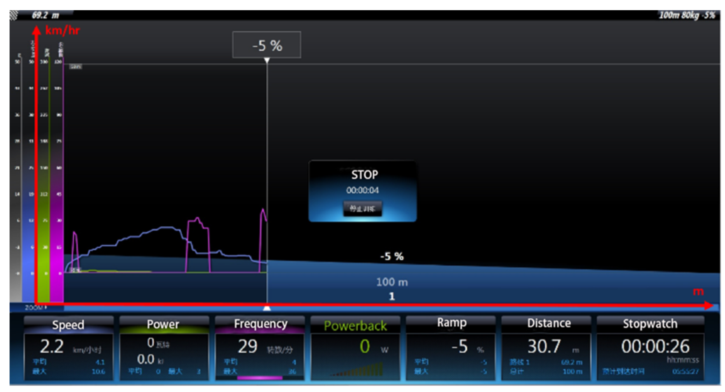
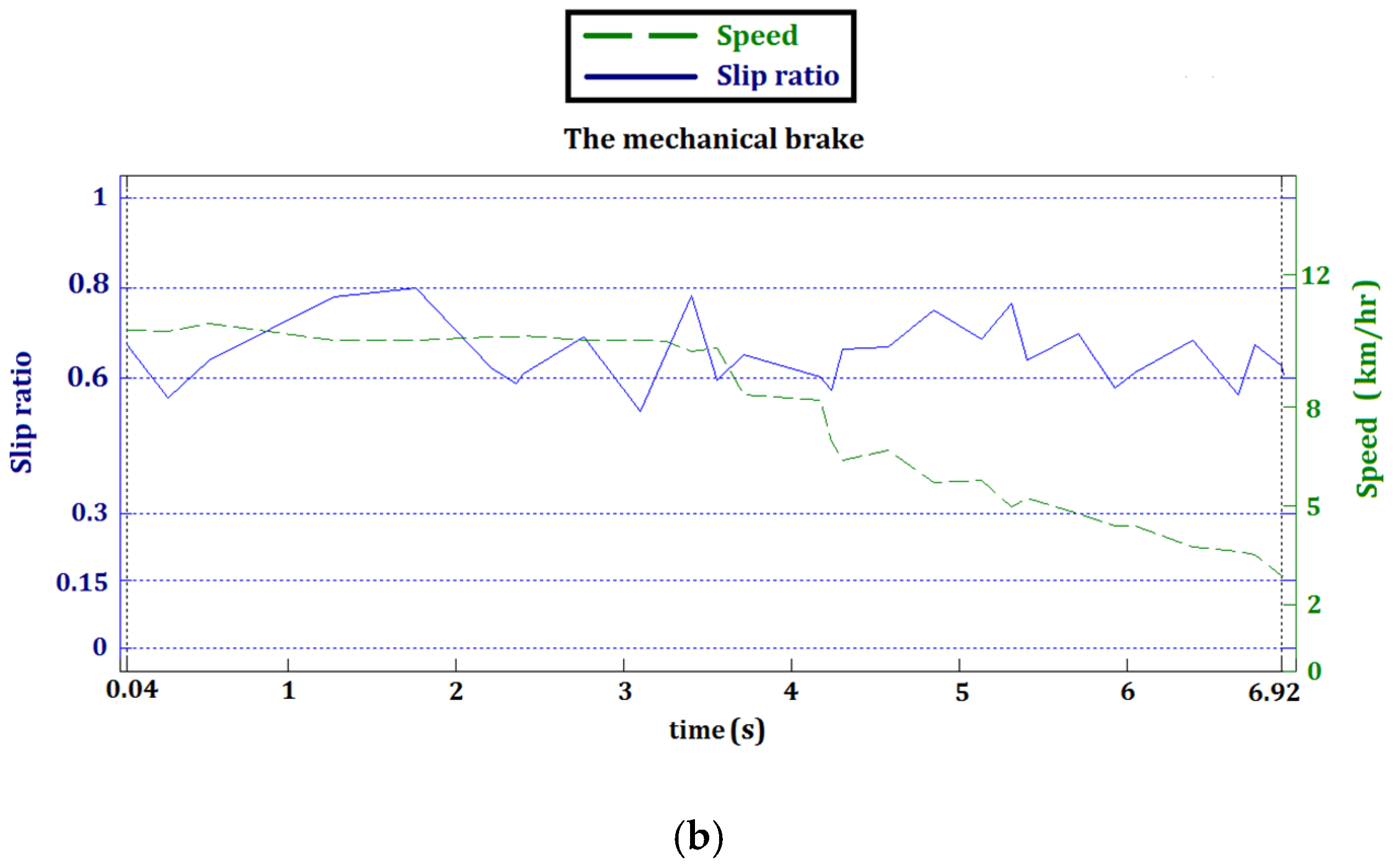
A virtual reality experimental platform-TACX I-Genius T2000 bike simulator [26] was adopted to conduct the hardware-in-the-loop experiments under various rider and road conditions (Figure 13). This simulator has an active resistance unit to emulate the effects of uphill and downhill ridings. For the downhill section of the road, the resistance unit increases the speed of the wheel to mimic downhill conditions. The ideal slip ratio for dry road is around 0.2 which was set to be the set point λ r e f of the SMC for ABS.
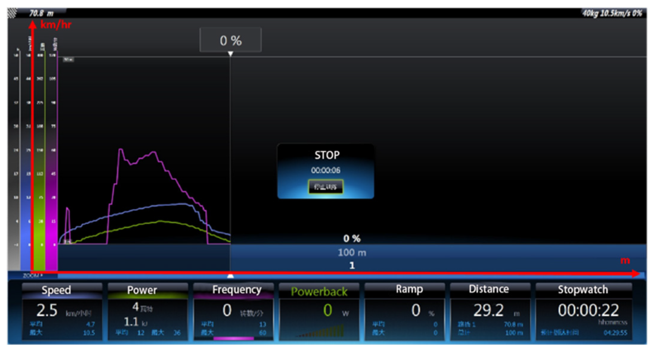
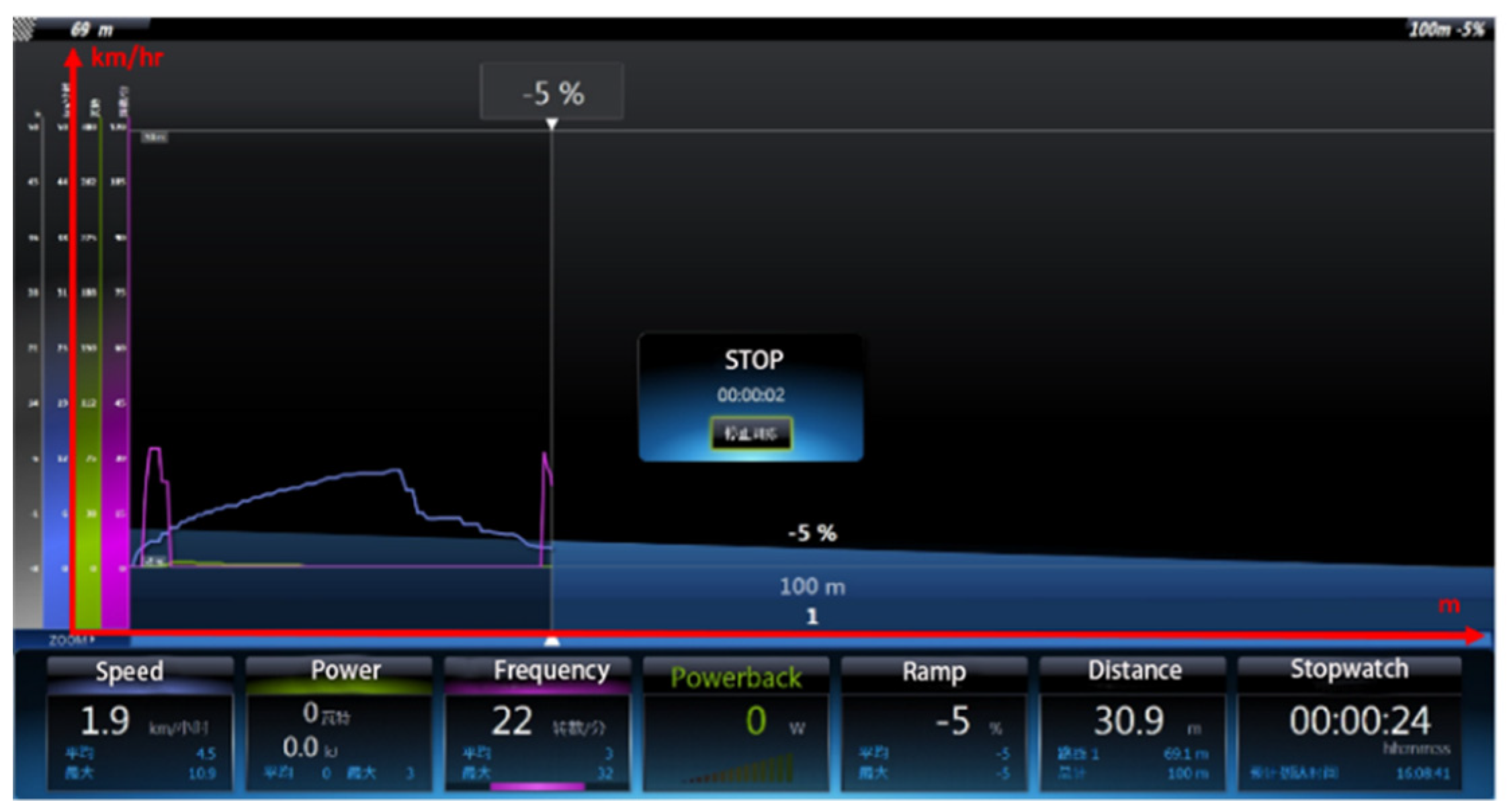
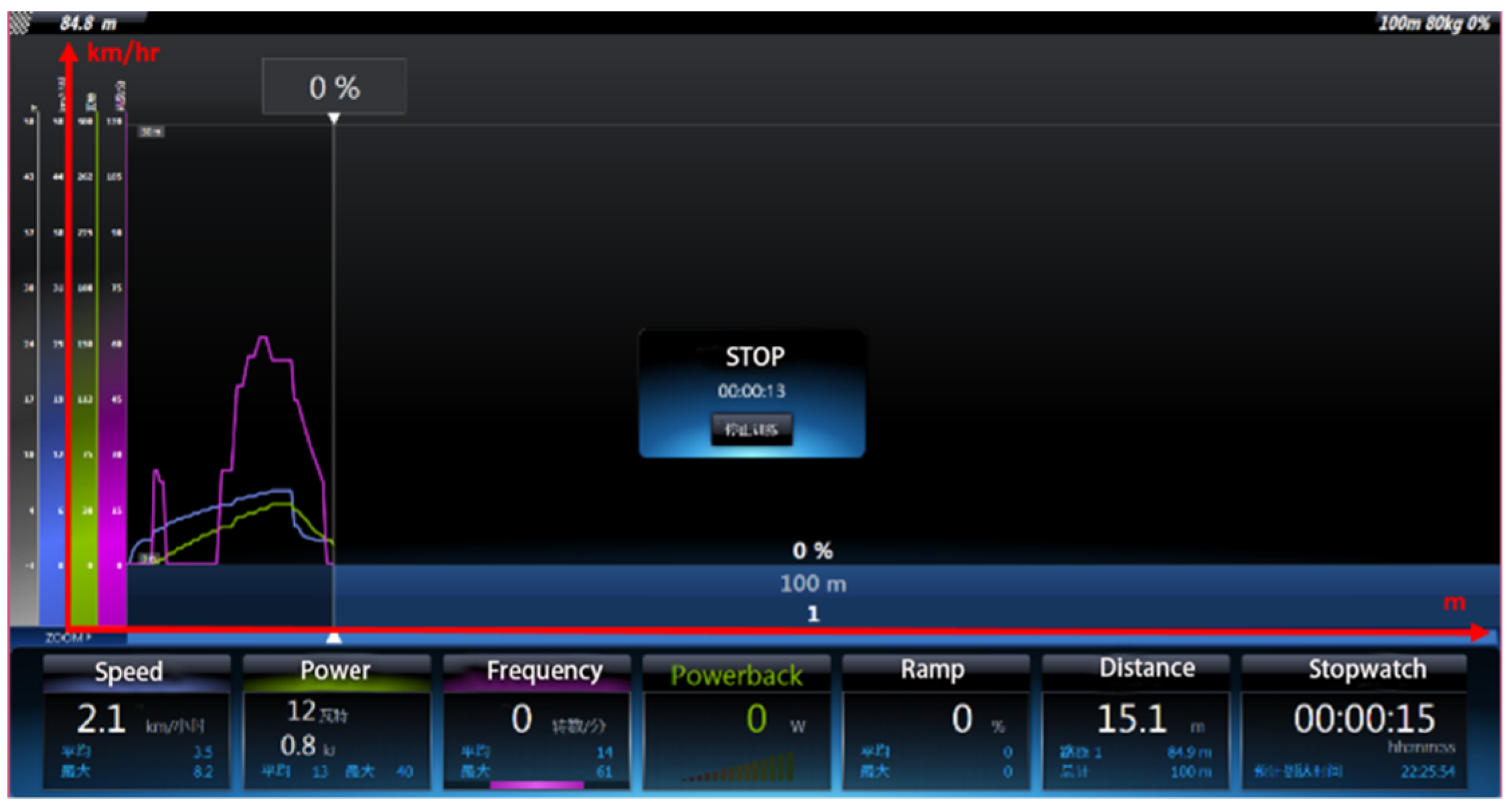
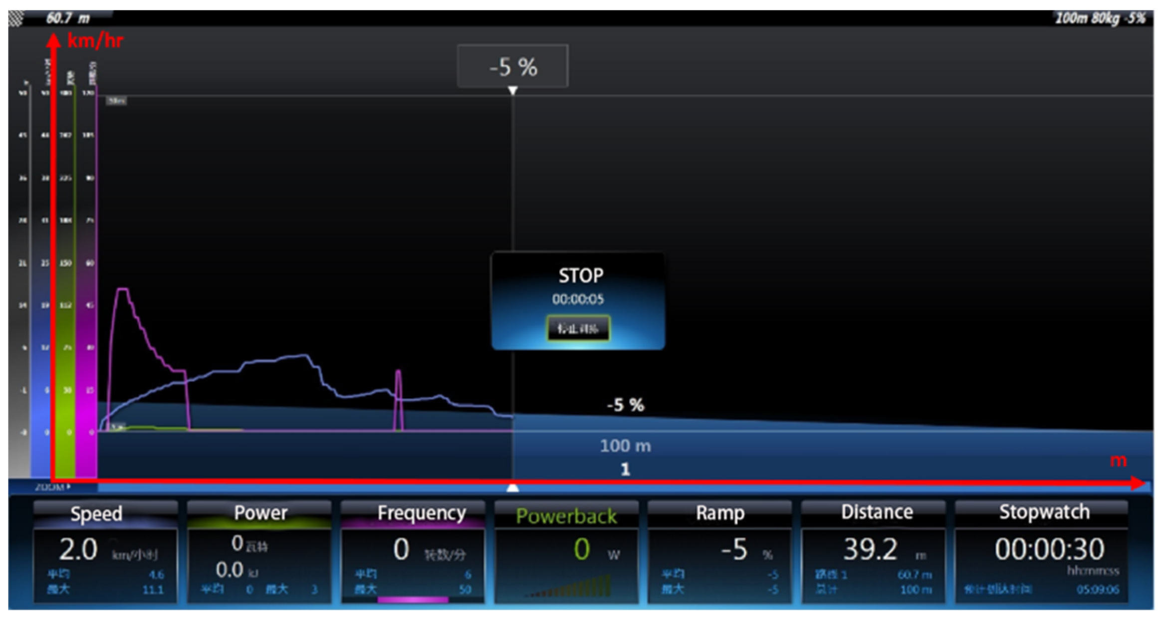
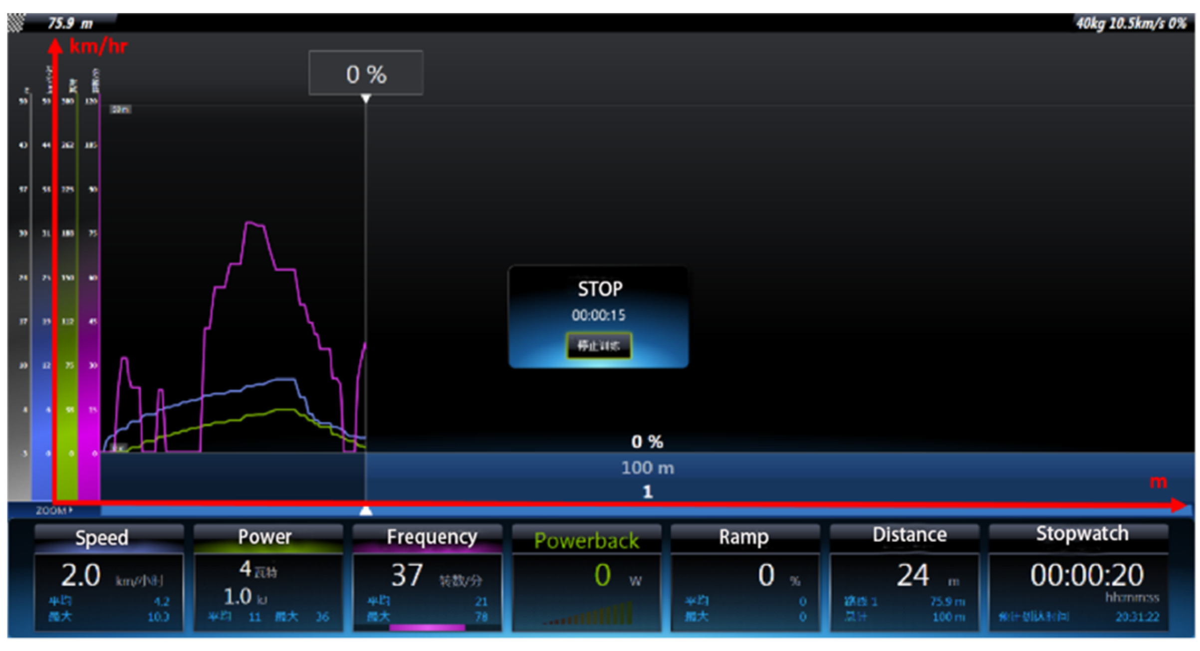
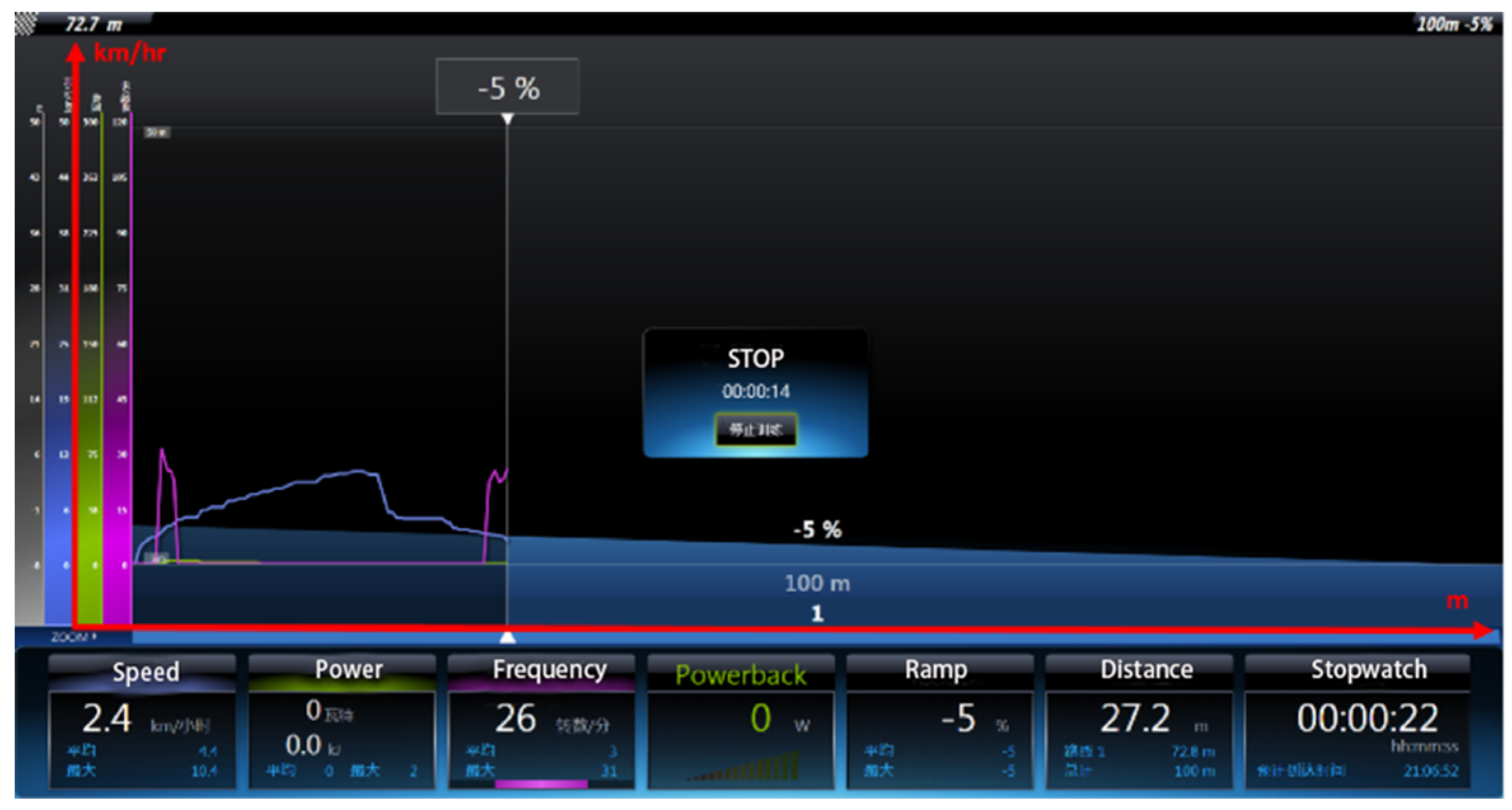
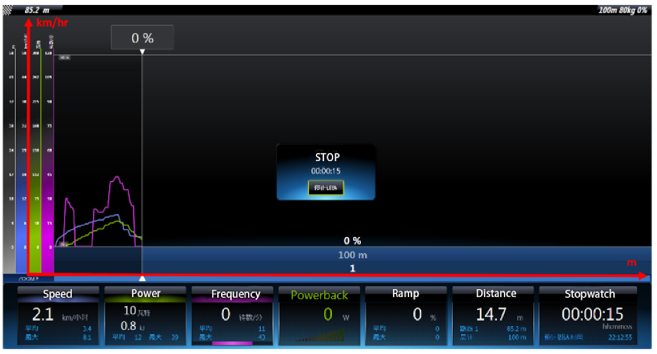
To verify the braking performance of the proposed design scheme, several experimental scenarios were tested on the virtual reality platform. Downhill declining gradients of 0% and −5 % and the cyclist with the weight of 40, 60, and 80 kg scenarios were tested. The proposed electromagnetic reversal brake and the traditional lower-arm three-phase short-circuit brake were tested and compared. The cyclist weight of 40 kg and declining gradient of 0% were set as the reference for braking tests. The braking control unit was set to activate after the electric bike accelerated to 10.5 km/hr. The testing distance was 100 m.
Detailed results are presented in Figure 14, Figure 15, Figure 16, Figure 17, Figure 18, Figure 19, Figure 20 and Figure 21. The electric bike stopped within 10 s for all cases listed in Table 3. The results indicated that the stopping distance increased with the increase in the weight of the cyclist and slope of the downhill section. For the electromagnetic reversal braking, the ultracapacitor provided additional braking energy when the bike moved downhill, the stopping distance decreased with the increase in the weight of the cyclist. Furthermore, with the increase in the weight of the cyclist, the starting torque was not sufficient for smooth starting of the motor using the sensorless FOC algorithm. This increase in weight reduced the maximum motor speed, as depicted in Figure 16, Figure 17, Figure 18, Figure 19, Figure 20 and Figure 21. The stopping distance of the electromagnetic reversal brake was considerably shorter than that using the lower-arm three-phase short-circuit brake for all cases. The result indicated satisfactory performance irrespective of the specific environmental conditions.
Finally, a test for ABS control was conducted. A convenient method to confirm the controllability of the electric bike during emergency braking involved observing the dynamic response of the slip ratio. The slip ratio could be satisfactorily controlled within the range 0.15–0.3 according to the proposed ABS control scheme (Figure 22). The braking performance for various operating scenarios in terms of the stopping distance is summarized in Table 3.

6. Discussions

In similar approaches dealing with the current issue—such as regenerative, kinetic, super-capacitor, and slip control-based braking—the braking effect might decreases considerably when the battery has been fully charged. In addition, low conversion efficiency generally results in unsatisfactory braking performance since traditional approaches dissipate back EMF to the load (power resistor or battery) rather than use it to boost braking effect. Here, the back EMF generated by the motor was used actively in the braking system. Braking effect is enhanced by intermittently reversing direction of the magnetic field force from driving to braking for the motor. The negative side is its sophisticated driver circuit and demagnetization risk due to the extreme conditions which might cause motor temperature rising. This deserves further study and is currently under investigation.

7. Conclusions

A novel driving/braking control design in which the motor driver and electromagnetic braking driver of the PMSM in a unit were combined was proposed for electric vehicles. The proposed system is cost effective. The FOC algorithm and sensorless control technique were combined to switch between driving or braking motor in an efficient manner. An ultracapacitor was added to the reverse braking mechanism to enhance the braking torque. The control strategy and hardware implementation were realized for a customized PMSM. The presented approach exhibited potential in achieving ABS control for future electric vehicles, which is functionally analogous to the engine brakes of the gasoline-powered vehicles but with better flexibility in braking torque distribution for long downhill riding. Experiments were conducted to demonstrate the feasibility of the proposed design.

8. Patent

C. L. Lin, E. P. Chen, and Y. C. Chen, “SENSORLESS ELCTRONIC BRAKE CONTROL SYSTEM”, Taiwan patent no. I 664804, 2019.

Author Contributions

Conceptualization, C.-L.L.; Methodology, C.-L.L.; Software, E.-P.C.; Validation, E.-P.C., J.C., and J.-H.T.; Formal analysis, E.-P.C., J.C., and J.-H.T.; Investigation, E.-P.C., J.C., and J.-H.T.; Resources, C.-L.L.; Writing—original draft preparation, E.-P.C.; Writing—review and editing, J.C., and J.-H.T.; Visualization, J.C. and J.-H.T.; Supervision, C.-L.L.; Project administration, C.-L.L.; funding acquisition, C.-L.L. All authors have read and agreed to the published version of the manuscript.

Funding

This research was supported by Ministry of Science and Technology, Taiwan under the grant MOST 106-2221-E-005- 001-MY2.

Conflicts of Interest

The authors declare no conflict of interest.

References

  1. Sahu, B.; Mohanty, K.B.; Pati, S. A comparative study on fuzzy and PI speed controllers for field-oriented induction motor drive. In Proceedings of the International Conference on Industrial Electronics, Control and Robotics, Wellington, New Zealand, 25–27 May 2009; pp. 2203–2212. [Google Scholar]
  2. Sharma, P.K.; Sindekar, A.S. Performance analysis and comparison of BLDC motor drive using PI and FOC. In Proceedings of the International Conference on Global Trends in Signal Processing, Information Computing and Communication, Jalgaon, India, 22–24 December 2016; pp. 485–492. [Google Scholar]
  3. Luo, J.; Namburu, M.; Pattipati, K.R.; Qiao, L.; Chigusa, S. Integrated model-based and data-driven diagnosis of automotive antilock braking systems. IEEE Trans. Syst. Man Cybern. Part A Syst. Hum. 2010, 40, 321–336. [Google Scholar] [CrossRef]
  4. Zambada, J.; Deb, D. Sensorless field oriented control of a PMSM. AN1078 Microchip Technol. Inc. 2010, 1–28. [Google Scholar]
  5. Jing, H.; Liu, Z.; Chen, H. A switched control strategy for antilock braking system with on/off valves. IEEE Trans. Veh. Technol. 2011, 60, 1470–1484. [Google Scholar] [CrossRef]
  6. Chen, Y.; Lv, X.; Shen, Y. Analysis of three-phase short circuit for dual-redundancy PMSM with low thermal coupling and non-electromagnetic coupling between windings. In Proceedings of the International Conference on Electrical Machines and Systems, Pattaya, Thailand, 25–28 October 2015; pp. 1434–1438. [Google Scholar]
  7. Yang, M.J.; Jhou, H.L.; Ma, B.Y.; Shyu, K.K. A cost-effective method of electric brake with energy regeneration for electric vehicles. IEEE Trans. Ind. Electron. 2009, 56, 2203–2212. [Google Scholar] [CrossRef]
  8. Naseri, F.; Farjah, E.; Ghanbari, T. An efficient regenerative braking system based on battery/supercapacitor for electric, hybrid, and plug-in hybrid electric vehicles with BLDC motor. IEEE Trans. Veh. Technol. 2017, 66, 3724–3738. [Google Scholar] [CrossRef]
  9. Li, Y.; Lv, C.; Zhang, J.; Zhang, Y.; Ma, W. High-precision modulation of a safety-critical cyber-physical system: Control synthesis and experimental validation. IEEE/ASME Trans. Mechatron. 2018, 23, 2599–2608. [Google Scholar] [CrossRef]
  10. Li, W.; Wang, X.; Leng, X.; Wang, M. Modeling and simulation of automobile braking system based on kinetic energy conversion. In Proceedings of the IEEE Vehicle Power and Propulsion Conference, Harbin, China, 3–5 September 2008; pp. 1–3. [Google Scholar]
  11. Chen, X.; Yang, J.; Yu, F. Model and simulation of a super-capacitor braking energy recovery system for urban railway vehicles. In Proceedings of the WASE International Conference on Information Engineering, Beidaihe, China, 16–17 August 2010; pp. 295–300. [Google Scholar]
  12. Ataei, M.; Khajepour, A.; Jeon, S. Reconfigurable integrated stability control for four-and three-wheeled urban vehicles with flexible combinations of actuation systems. IEEE/ASME Trans. Mechatron. 2018, 23, 2031–2041. [Google Scholar] [CrossRef]
  13. Lin, W.C.; Lin, C.L.; Hsu, P.M.; Wu, M.T. Realization of anti-lock braking strategy for electric scooters. IEEE Trans. Ind. Electron. 2014, 61, 2826–2833. [Google Scholar] [CrossRef]
  14. Lin, C.L.; Yang, M.Y. Design of anti-lock braking system for electric vehicles via short-circuit braking. In Proceedings of the IEEE International Conference on Mechanic Automation and Control Engineering, Inner Mongolia, China, 15–17 July 2011; pp. 1176–1179. [Google Scholar]
  15. Lin, C.L.; Lin, W.C. ABS control design for two-wheel drive electric vehicles. In Proceedings of the IEEE International Conference on Mechanic Automation and Control Engineering, Inner Mongolia, China, 15–17 July 2011; pp. 1011–1014. [Google Scholar]
  16. Abassi, M.; Khlaief, A.; Saadaoui, O.; Chaari, A.; Boussak, M. Performance analysis of FOC and DTC for PMSM drives using SVPWM technique. In Proceedings of the IEEE International Conference on Sciences and Techniques of Automatic Control & Computer Engineering, Monastir, Tunisia, 21–23 December 2015; pp. 228–233. [Google Scholar]
  17. Kumar, P.; Dhundhara, S.; Makin, R. Performance analysis of PMSM drive based on FOC technique with and without MRAS method. In Proceedings of the International Conference on Recent Advances and Innovations in Engineering, Jaipur, India, 23–25 December 2016; pp. 1–6. [Google Scholar]
  18. Texas Instruments Incorporated. Field Orientated Control of 3-Phase AC-Motor; Literature Number: BPRA073.1998; Texas Instruments Incorporated: Dallas, TX, USA, 2017. [Google Scholar]
  19. DeCarlo, R.A.; Zak, S.H.; Matthews, G.P. Variable structure control of nonlinear multivariable systems: A tutorial. Proc. IEEE 1988, 76, 212–232. [Google Scholar] [CrossRef] [Green Version]
  20. Suzuki, T.; Fujimoto, H. Slip ratio estimation and regenerative brake control without detection of vehicle velocity and acceleration for electric vehicle at urgent brake-turning. In Proceedings of the IEEE International Workshop on Advanced Motion Control, Nagaoka, Niigata, Japan, 21–24 March 2010; pp. 273–278. [Google Scholar]
  21. Chen, S.Y.; Chiang, H.H.; Liu, T.S.; Chang, C.H. Precision motion control of permanent magnet linear synchronous motors using adaptive fuzzy fractional-order sliding-mode control. IEEE/ASME Trans. Mechatron. 2019, 24, 741–752. [Google Scholar] [CrossRef]
  22. Slotine, J.J.E.; Li, W. Applied Nonlinear Control; Prentice-Hall: Englewood Cliffs, NJ, USA, 1991. [Google Scholar]
  23. Kiencke, U.; Nielsen, L. Automotive Control Systems; Springer: Berlin/Heidelberg, Germany, 2000. [Google Scholar]
  24. Lin, C.L.; Hsieh, M.C.; Chen, T.C. Integrated driving and braking control unit for electric bike. SAE Int. J. Veh. Dyn. Stab. NVH 2018, 2, 223–242. [Google Scholar] [CrossRef]
  25. Lahue, K.C. Automotive Brakes and Antilock Braking Systems; West Publishing Co.: Eagan, MN, USA, 1995. [Google Scholar]
  26. Tacx i-Genius T2000 Virtual Reality Trainer–Multiplayer. Available online: https://www.evanscycles.com/tacx-i-genius-t2000-virtual-reality-trainer-multiplayer-EV152529 (accessed on 21 March 2020).
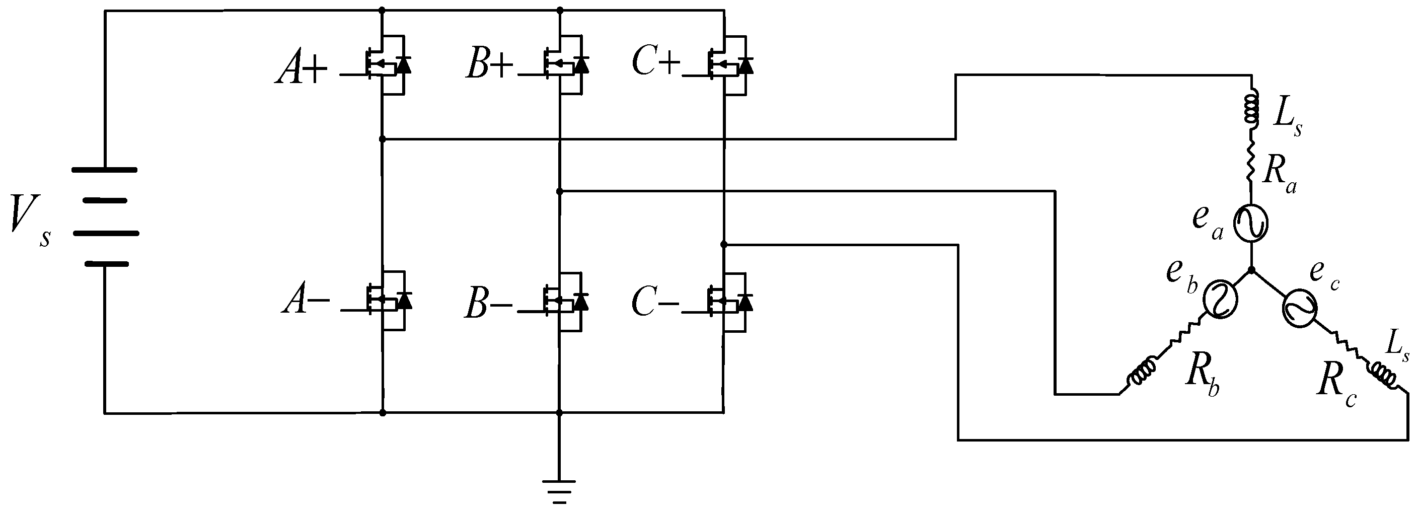
Figure 1. Typical three-phase inverter and PMSM.
Actuators 09 00022 g001
Figure 2. Rotor position estimation and control.
Actuators 09 00022 g002
Figure 3. Circuit diagram as the system stays in driving mode.
Actuators 09 00022 g003
Figure 4. Schematic of the three-phase back EMF of the PMSM.
Actuators 09 00022 g004
Figure 5. Circuit diagram of the system in the braking mode.
Actuators 09 00022 g005
Figure 6. Current conduction loop during braking when A + , B + , and C are controlled at ‘ON’.
Actuators 09 00022 g006
Figure 7. Direction of the combined magnetic field forces of the PMSM stator coils constructed by six basic voltage vectors when braking.
Actuators 09 00022 g007
Figure 8. Simplified framework of the braking control scheme.
Actuators 09 00022 g008
Figure 9. Hardware architecture.
Actuators 09 00022 g009
Figure 10. Integrated system architecture.
Actuators 09 00022 g010
Figure 11. Flowchart of the driving/braking control unit.
Actuators 09 00022 g011
Figure 12. Output voltage of the SVPWM signal in region 4 of the vector distribution map.
Actuators 09 00022 g012
Figure 13. The experimental platform.
Actuators 09 00022 g013
Figure 14. Results for flat road, cyclist weight 40 kg, and lower-arm three-phase short-circuit braking.
Actuators 09 00022 g014
Figure 15. Results for road slope −5%, cyclist weight 40 kg, and lower-arm three-phase short-circuit braking.
Actuators 09 00022 g015
Figure 16. Results for flat road, cyclist weight 80 kg, and lower-arm three-phase short-circuit braking.
Actuators 09 00022 g016
Figure 17. Road slope −5%, cyclist weight 80 kg, and lower-arm three-phase short-circuit braking.
Actuators 09 00022 g017
Figure 18. Results for flat road, cyclist weight 40 kg, and electromagnetic reversal braking.
Actuators 09 00022 g018
Figure 19. Results for road slope −5%, cyclist weight 40 kg, and electromagnetic reversal braking.
Actuators 09 00022 g019
Figure 20. Results for flat road, cyclist weight 80 kg, and electromagnetic reversal braking.
Actuators 09 00022 g020
Figure 21. Results for road slope −5%, cyclist weight 80 kg, and electromagnetic reversal braking.
Actuators 09 00022 g021
Figure 22. Comparison of the slip ratio of (a) the proposed brake and (b) the traditional mechanical brake on the TACX simulator.
Actuators 09 00022 g022aActuators 09 00022 g022b
Table 1. Order of vector combination of V r e f in each region.
Region of VrefThe Order of Vector Combination of Vref
S1(0° ≤ θ ≤ 60°)V0V1V2V7V7V2V1V0
S2(60° ≤ θ ≤ 120°)V0V3V2V7V7V2V3V0
S3(120° ≤ θ ≤ 180°)V0V3V4V7V7V4V3V0
S4(180° ≤ θ ≤ 240°)V0V5V4V7V7V4V5V0
S5(240° ≤ θ ≤ 300°)V0V5V6V7V7V6V5V0
S6(300° ≤ θ ≤ 360°)V0V1V6V7V7V6V1V0
Table 2. Control logic of six basic voltage vectors defined by SVM for driving and braking modes.
Voltage VectorControl Logic of DrivingVoltage VectorControl Logic of Braking
Phase APhase BPhase CPhase APhase BPhase C
V0000V7111
V1100V6101
V2110V5001
V3010V4011
V4011V3010
V5001V2110
V6101V1100
V7111V0000
Table 3. Experimental results under various conditions.
Road ConditionBraking Speed (km/hr)Cyclist Weight (kg)Brake MethodStopping Distance (m)
flat10.540lower-arm three-phase short-circuit brake29.2
electromagnetic brake24
60lower-arm three-phase short-circuit brake32.1
electromagnetic brake26.3
8.280lower-arm three-phase short-circuit brake15.1
8.1electromagnetic brake14.7
downhill slope −5% * 10.540lower-arm three-phase short-circuit brake30.9
electromagnetic brake27.2
60lower-arm three-phase short-circuit brake32.5
electromagnetic brake26.4
80lower-arm three-phase short-circuit brake39.2
electromagnetic brake30.7
* The percentage of downhill slope equals sin−1(θ) where θ is the inclination angle of the road.