Article

Effect of Electromagnetic Damping on System Performance of Voice-Coil Actuator Applied to Balancing-Type Scale

School of Mechanical Engineering, Pusan National University, 2, Busandaehak-ro 63beon-gil, Geumjeong-gu, Busan 46241, Korea
*
Author to whom correspondence should be addressed.
Actuators 2020, 9(1), 8; https://doi.org/10.3390/act9010008
Submission received: 14 December 2019 / Revised: 15 January 2020 / Accepted: 17 January 2020 / Published: 1 February 2020

Abstract

:
Changing a time-varying magnetic field induces an electromotive force (EMF) in non-magnetic conductive materials, resulting in an eddy current across the conductor. Thus, electromagnetic damping can be used as viscous damping. This study theoretically and experimentally investigates the electromagnetic damping characteristics of a bobbin-wounded coil with an attached cantilever beam floating over a permanent magnet; the beam is balanced by electromagnetic force compensation (EMFC) instead of applied weight. System identification is carried out for the mass (m), damping coefficient (c), and spring constant (k) values. The presence of a back EMF seen in either conductive or non-conductive material responses in the experiments includes the step input and corresponding output responses to measure the electromagnetic damping force with and without a voice-coil actuator (VCA). The results were validated using bobbins of conductive (aluminum) and non-conductive (plastic) materials. The experimental results for the conductive material show that the electromagnetic damping force is 10 times greater than that of the non-conductive material; the opposite was true in the case without a VCA, where the force was almost zero for the non-conductive material. In conclusion, conductivity is directly related to the electromagnetic damping force, which affects the performance of a VCA.

1. Introduction

1.1. Background

Scale and balance analogs are used to weigh small items such as minor food ingredients as well as large items the size of animals and people. However, these instruments work in many different ways. Various operations allow scales and balances to function differently because they vary functionally, sometimes based on different applicable principles; balances measure mass while scales measure weight. Balances calculate mass by stabilizing an unspecified mass against an identified mass. Furthermore, some balances use a force-restoration mechanism that creates a force to balance the force deployed by the unspecified mass. Scales, on the other hand, determine weight by measuring drift; a spring is deformed by the load and the force needed to buckle the spring is measured and converted to weight. Some deflection-type scales use uncomplicated mechanisms that are fast but have low accuracy; balances have high accuracy but tend to be slow.
Despite the existence of different technologies in balances, more than half of modern digital balances use a force-restoration mechanism. Electromagnetic force restoration is often used in scientific balances. The primary principle that makes it a balance and not a scale, however, is still identical: a counteracting force is produced and compared to the unspecified mass. The weighing pan is attached to an electromagnetic coil through which electric current flows. The coil moves in a magnetic field created by an amplifier. The amplifier preserves the required current to keep the lever balanced with the mass on the pan [1].
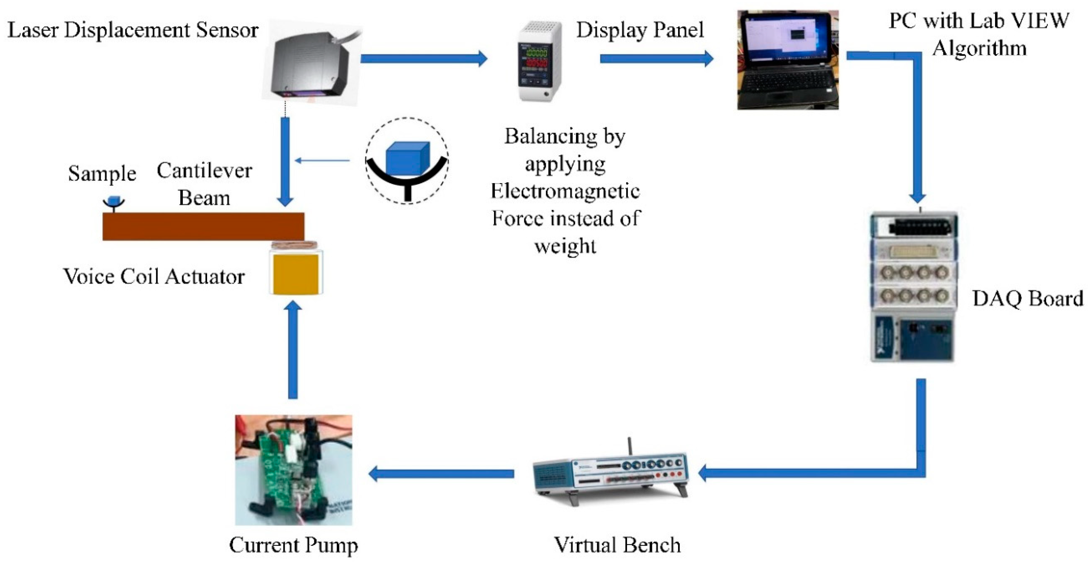
Figure 1 shows the electromagnetic force restoration design where an electromagnetic force is applied to balance the beam. The amount of electric current required to balance the beam changes according to the weight of the sample that is placed on it.
An electromagnetic compensated weighing cell is used frequently if high accuracy must be achieved in weighing applications. For example, such applications are check-weighed and balanced in filling plants [2].
Control schemes for electromagnetic force compensation (EMFC) mechanisms have been developed to improve the speed and accuracy of check-weighers for better speed and accuracy [3]. The model of these measurement systems can be simplified and improved using EMFC control schemes to easily identify the model parameters (a damping coefficient and a spring constant) [4]. Voice-coil actuators (VCAs) are used due to their fast response time and rectilinear motion [5]. The resulting magnetic field resists the motion of the conductor so that a theoretical model of the system is derived using electromagnetic induction theory. This enables the approximation of the damping force induced in the structure. Experiments were conducted on the foundation of theoretical models determining that the eddy current damping mechanism adds a crucial amount of damping to the beam [6].
Electromagnetic damping is used as a form of viscous damping. The magnetic field that is created by a permanent magnet is calculated and the electromagnetic damping is measured accurately. Drop and dynamic tests were chosen as a substitute for steady and dynamic damping [7]. Three different conductive coils, including a cylindrical, square tube, and circular sheet were employed to determine the effect of the coil shapes on the vibration damping of the beam [8]. A theoretical model for the eddy current damper (ECD) was derived using electromagnetic theory [9]. The induced electromagnetic force (EMF) acting on the electric wire was effective in suppressing the beam’s vibrations [10].

1.2. Objective

In this study, the effect of electromagnetic damping on voice coil actuator system performance applied to a balance-type scale to obtain a fast response time was investigated by conducting different tests using conductive and non-conductive materials to check the system response and linear behavior of VCAs. We modeled a cantilever beam as a spring and attached coil as a current was applied; as a result, it floated in a permanent magnet generating a magnetic field. The back EMF was produced generating an eddy current in the conductor (bobbin) with a coil. This acts as an electromagnetic damping force that affects system performance. Therefore, we proposed to use non-conductive material to overcome the electromagnetic damping force and its effect on VCA performance, which is applied in balancing-type scales. Figure 2 shows the experimental setup to balance the beam.
The bobbin connected to the beam (plastic plate) within the VCA housing is deflected when a load applied; the bobbin rests within an electromagnetic field. When the bobbin was displaced, a sensor indicates the plate to apply a force to restore the bobbin to its resting position. The bobbin plate increases the current through a coil of wire resulting in an upward (electromagnetic) force generated within the magnetic field according to the electrodynamic “right-hand rules.” The balancing scale increases the current through the wire until the upward force matches the load and the beam is realigned. The force restoration balancing-type scale measures the increased current and converts it to a weight.

2. Theoretical Analysis

2.1. Electromagnetic Damping Principle

The electromagnetic damping is one of the most fascinating damping techniques as it uses an electromagnetically induced current to control/regulate/slow down the motion of an object without any physical contact with the moving object. To understand this damping technique, it is important to understand two concepts: eddy currents and electromagnetic induction.
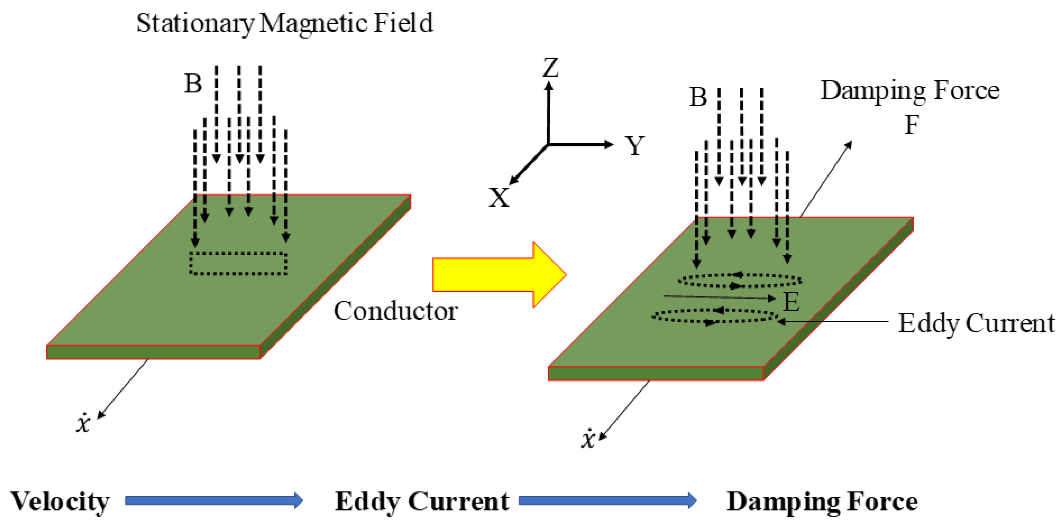
An eddy current is caused when a moving conductor intersects a stationary magnetic field or vice-versa. The relative motion between the conductor and magnetic field generates the circulation of the eddy current within the conductor. These circulating eddy currents induce their magnetic field causing a resistive force. These currents dissipate due to the electrical resistance and the generated force eventually disappears, thus, removing the energy of the dynamics system. As the resistive force induced by eddy currents is proportional to the relative velocity, the conductor and magnet can be allowed to function as a form of viscous damping [7].
To generate the electromagnetic damping force, motion between a magnet and a conductive sheet is necessary as it causes a change in the magnetic field and creates an electromagnetic damping force as seen in Figure 3.
The electromagnetic damping force can be expressed by adopting Lorentz’s Law, as follows [8]:
F = ( J ×   B )   d V ,
where J is the eddy current density, B is the magnetic flux density and V is the volume of the conductive sheet.
The eddy current density induced in the conductive plate can be expressed as Equation (2) [9,11]:
J = σ ( v × B ) ,
where σ is the electrical conductivity of the conductive sheet and v . is the relative velocity.
The electromagnetic damping force can be expressed as Equation (3) [10,12]:
F = σ v ( B 2 ) V
Then, the electromagnetic damping coefficient can be expressed as Equation (4).
c = σ ( B 2 ) V
From Equation (3), it can be seen that the electromagnetic damping force increases by increasing the velocity in the direction opposite to the direction of the motion; the electromagnetic damping force also increases as the volume through which the magnetic flux passes is larger. The electromagnetic damping force is greatly influenced by magnetic fields and increases according to the current applied to the coil. This causes the eddy current to increase as the electromagnetic damping force grows.

2.2. Use of Electromagnetic Damping in Voice Coil Actuator

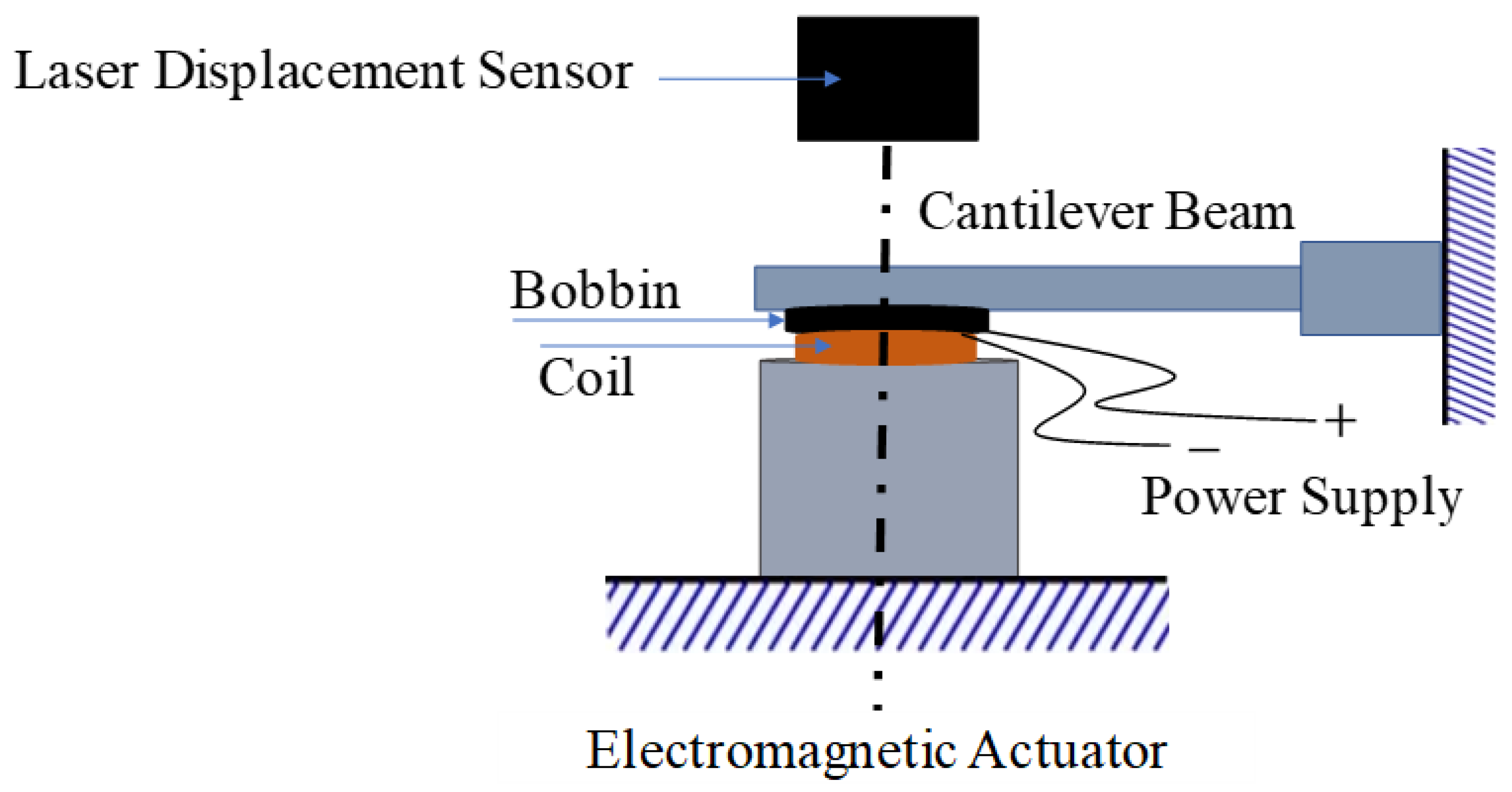
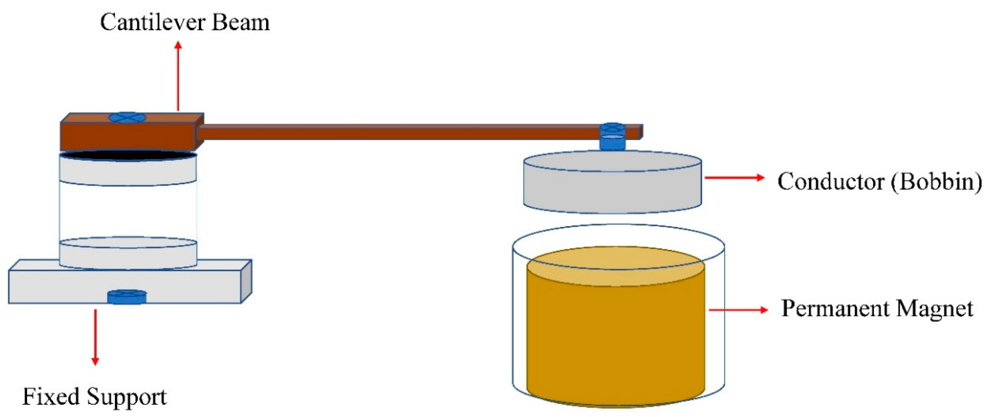
A passive damper (cantilever beam with a permanent magnet) and conductor (bobbin) are attached to a cantilever beam (plastic plate) moving perpendicularly across the permanent magnet producing a magnetic field without physical contact, thus producing an EMF.
The induced EMF results in a current across the conductor (bobbin). This induced current is called an eddy current (electromagnetic damping). This induced current generates its magnetic field in the system in swirl shape around the conductor (bobbin) and opposes the motion through which it is induced. The distance between the permanent magnet housing and conductor decreases as the damping force increases; however, the electromagnetic damping force is proportional to the induced eddy current, magnetic field strength, and object speed. This implies that the faster the bobbin moves, the greater the damping will be and the slower the motion of the bobbin. As a result, the damping is lower, which results in the cantilever beam stopping smoothly.
In our research, we investigated electromagnetic damping using cantilever beam work as a balancing-type scale dealing with an EMFC-type load cell to balance the scale as the VCA operates.
The generated electromagnetic damping used by the VCA depends on the stiffness and damping coefficient of the beam (plastic plate) and the material’s conductivity, both of which play a vital role in improving the performance linearity and fast time response. If the material is more conductive, it affects the linear behavior and time response of the VCA.
In our case, we used a plastic plate as a cantilever beam because of its natural non-conductive property. The attached bobbin is made of aluminum, which is conductive with a magnet so that the electromagnetic damping affects the VCA performance. Then, we used the attached plastic bobbin plastic to improve the VCA linearity and response time. Figure 4 shows the setup used to check electromagnetic damping in the VCA.

3. System Modelling for System Identification

3.1. System Modelling

We have modeled two different systems: a mechanical system and an electrical system. The mechanical system includes mass (m) and stiffness (k), which are calculated using the cantilever beam with the attached bobbin and the electrical system with electromagnetic damping (c). The system responses for different specimens were calculated to confirm their validity.

3.2. Modeling of Cantilever Beam

The cantilever beam modeling is a voice-coil actuator mechanical system used to investigate the system performance. The cantilever beam has a fixed end while the other is attached to a mass (bobbin) that moves. The attached mass, which is a bobbin with a coil wound around it, is the electrical system of the VCA. The dynamic performance of the VCA is modeled as a time-dependent mass-spring-damper system with coupling between the mechanical and electrical parameters.
Figure 5 shows the real and m, c, and k mechanical system of the VCA and Figure 6 shows the experimental setup used to investigate the electromagnetic damping. Figure 7 shows the schematic diagram of the VCA and Table 1 shows the physical and geometrical properties of the cantilever beam.
F = m x + c x ¨ + k x ˙
F is the Lorentz force basic operating principle of VCA as the current, I , flow in the coil produces such force; m is the mass of attached bobbin, c is the electromagnetic damping, and k is the spring constant of a cantilever beam.
F = N B i L = k f i ,
where N is the number of turns, L the length of the copper coil, and B is the magnetic flux density of the coil. The force generated by the Lorentz law does not vary linearly with the position of the operating region about a constant current input because the magnetic flux density is not uniform according to the position of the operating region; such a phenomenon makes precision control difficult.
By substituting Equation (6) in (5) we obtain:
k f i = m x ¨ + c x ˙ + k x

3.3. Electrical Modelling of Voice-Coil Actuator (VCA)

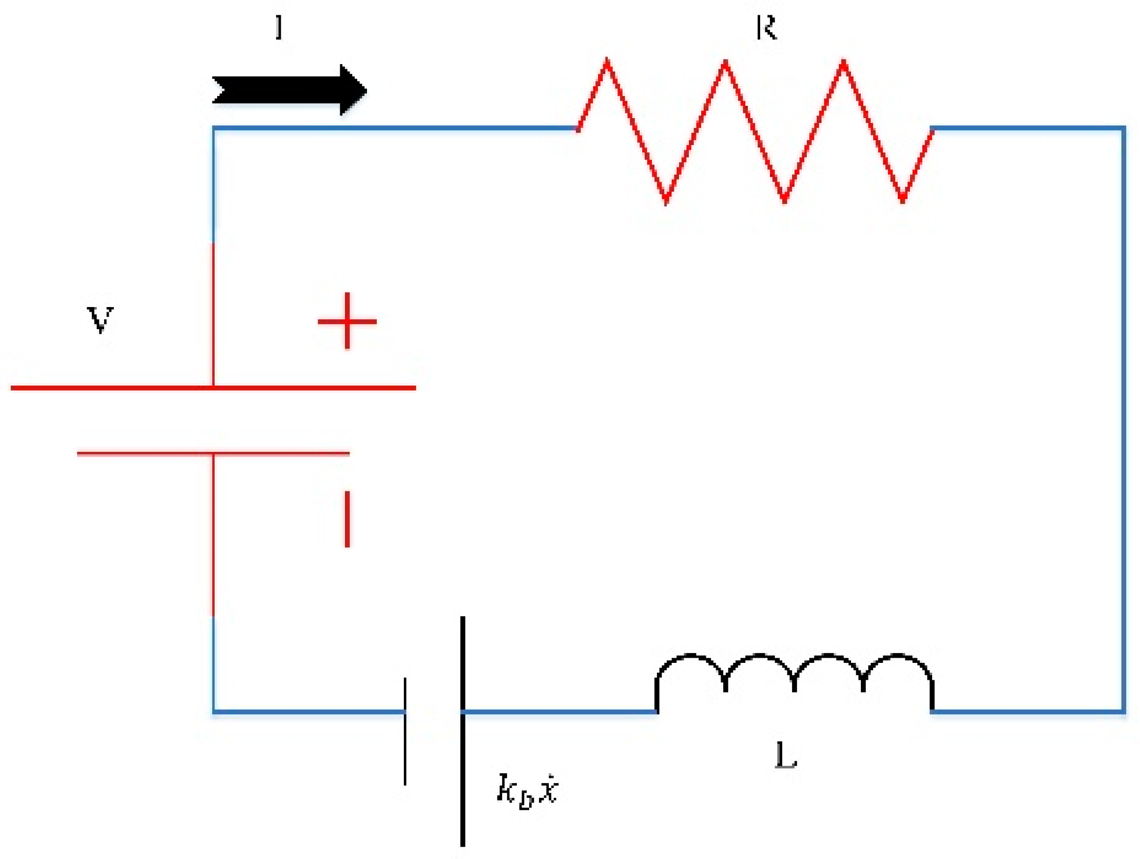
The electrical system of the VCA is shown in Figure 8; it is used to investigate the electromagnetic damping, when a power supply is attached to the VCA, by recording-system response.
V = L d i d t + R i + k b x ˙
V is the external supply; R and L are the resistance and the inductance of the coil, respectively; k b x ˙ is the back electromotive force induced by the displacement of the bobbin; and k b is the back electromotive force constant. Table 2 shows the system specifications.

3.4. Force–Current Relationship of VCA

The experiment was performed using variable direct current (DC) power supply for different current values to the VCA; the force generated was determined by a load cell in a gram force and the value was displayed on a connected digital indicator (weighing controller). The specifications of the hardware and values of the parameters used in the experiment are shown in Table 2.
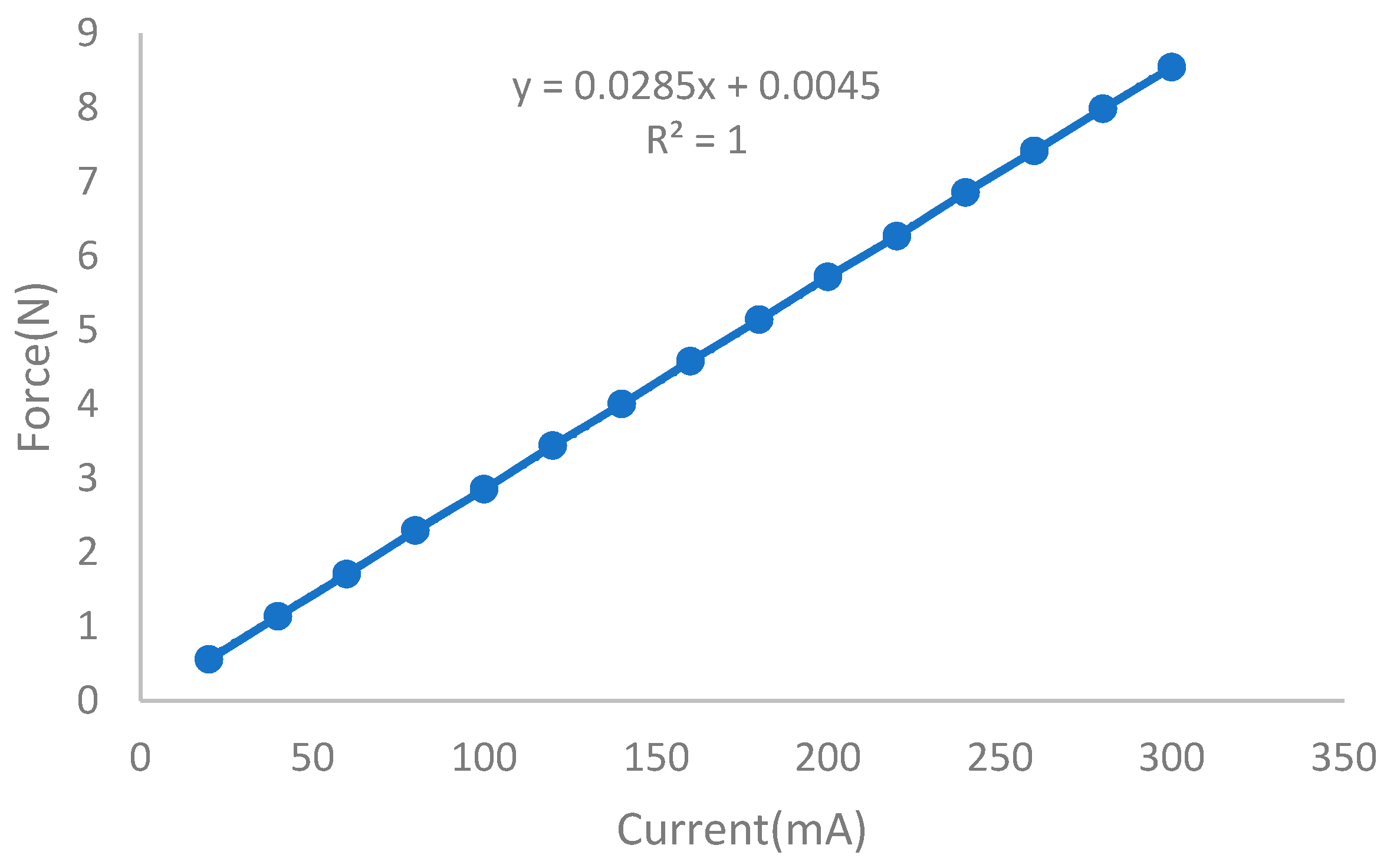
For different current values, a different magnetic force was generated to determine the force–current relationship of the voice coil actuator. The experimental results are shown in Table 3 and a regression analysis can be seen in Figure 9.
By using regression analysis, we know the force sensitivity/constant ( k f , 28.46   N / A ).
F = k f × I
Force is different according to the distance of the bobbin from the center of the coil length even under the same current. According to the Lorentz law, the generated force does not vary linearly with a constant operating region for constant input, which means that the magnetic flux density does not act uniformly when reporting the position of the constant operating region. Due to this phenomenon, achieving precise constant motion is difficult. Figure 10 shows the experimental results of the thrust force (F) depending on the bobbin location when a constant current was supplied to the VCA. This indicated that the proper operating region is limited to ± 0.5   mm from its center if the force is linear in the input current of the K f = 28.46   N / A .

3.5. Simulink Model

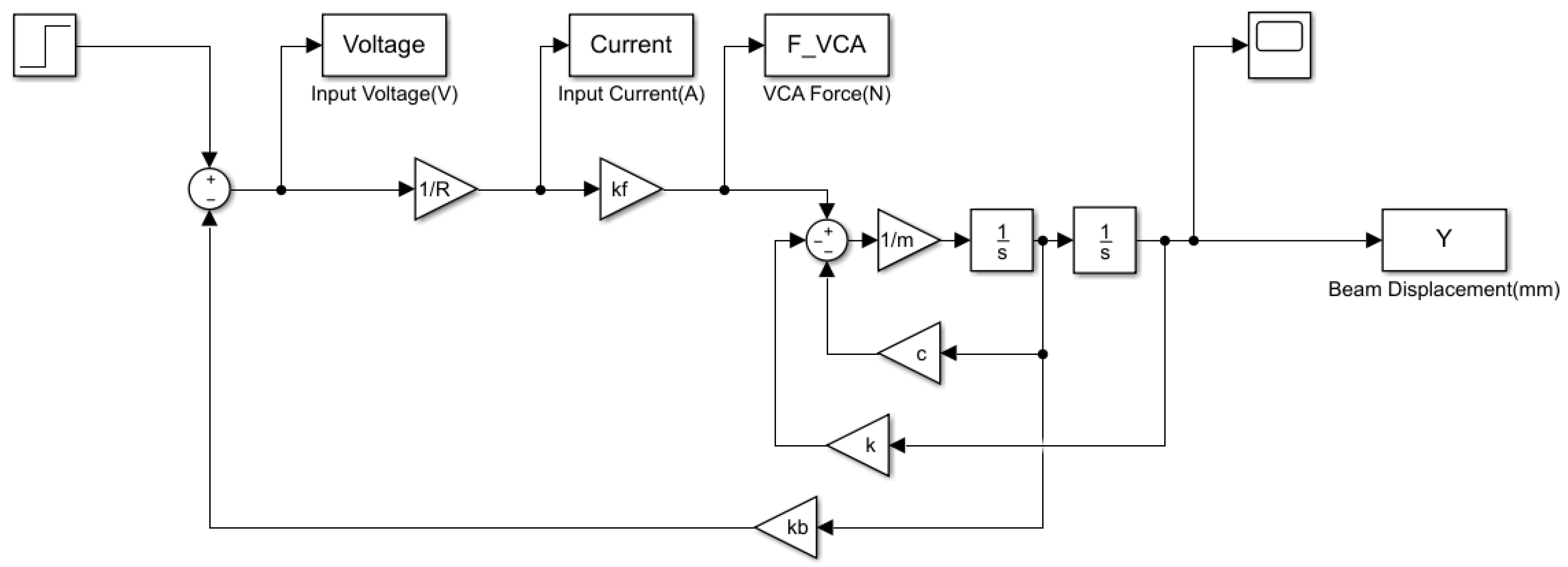
Equations (7) and (8) were combined to make a simulation model for the VCA using MATLAB/Simulink as shown in Figure 11. From the figure, we calculated the simulated responses of the step input voltage to the electrical part of the voice coil actuator as seen in Equation (8). This generates a force to push the bobbin towards the permanent magnet. There a phenomenon called electromagnetic damping occurs, which affects the entire VCA time response.

4. System Identification

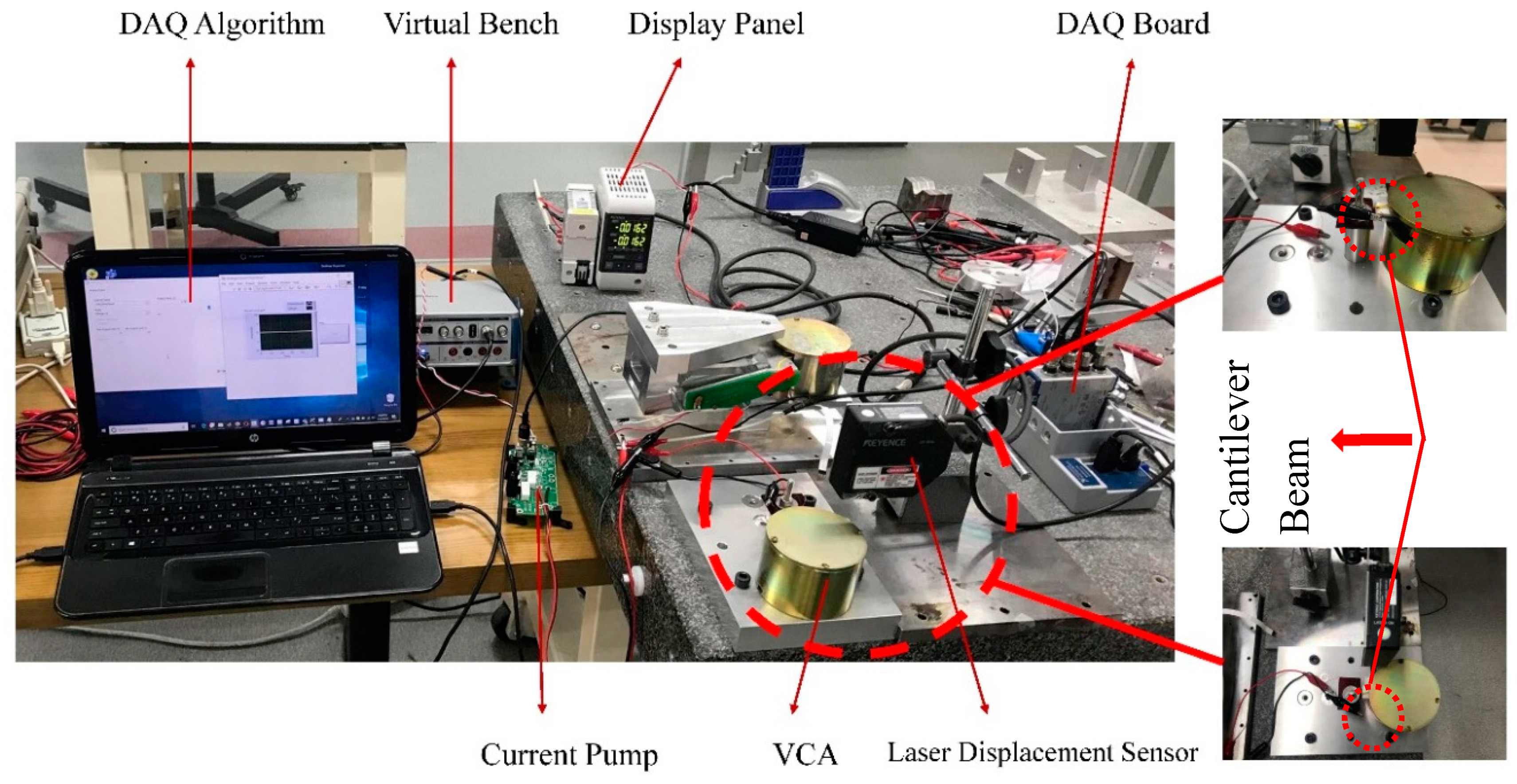
Figure 12 shows the experimental setup of the voice coil actuator to estimate the system parameters. The parameters with and without the VCA were investigated experimentally and theoretically. The cantilever beam deflection was detected by a laser displacement sensor as we provided input voltage from the data acquisition (DAQ) algorithm, which is amplified using NI virtual bench by generating the input current to operate the VCA.

4.1. Spring Constant with VCA

To investigate the spring constant ( k ) of the mass-spring system, we conducted experiments with different voltages to obtain the deflection values.
F s = k x
The experiment was conducted to determine the spring constant of the plastic plate attached to the bobbin. As the voltage changed in Figure 8, the current flowing through the VCA circuit changed resulting in the corresponding Lorentz force ( F ). As a result, the bobbin was forced to deflect the plastic plate. The data acquisition device (National Instruments (NI) cDAQ-9174) was used to generate the actuator command voltage and to acquire the plate displacement at a sampling rate of 5 kHz. The cantilever beam deflection was detected by a laser displacement sensor (LK-GD500) mounted on the actuator.
Using the setup in Figure 12, we calculated the spring constant of the cantilever beam, experimentally recording the deflection using a laser sensor.
Table 4 summarizes the input conditions of the voltage, corresponding force, and beam deflection at each current for the experimental and theoretical values.
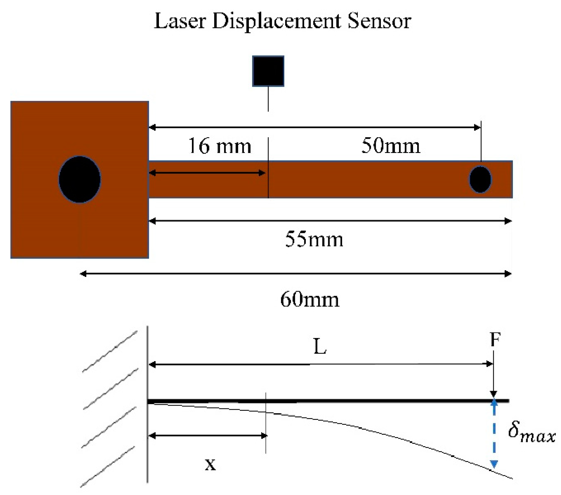
Figure 13 represents the laser sensor scenario as we record the deflection of the beam at the middle of the fixed and loading point, which is equal to 16   mm . Therefore, we recorded the deflection from a particular point using a laser displacement sensor. From that point, we want to know the full deflection of the cantilever beam using cantilever beam deflection theory to find the unknown deflection at the measurement point to compare with the theoretical deflection and deal with the spring constant ( k ) .
Therefore, we used the deflection formula at any section in terms of the unit load ( x ).
E I = P x 2 6 y ( 3 L x ) or E I y = 3 w l x 2 + w x 2 6
The following formula is used to obtain the maximum deflection:
y m a x = w l 3 3 E I
We calculated the deflection for each load (force) and found the spring constant for the cantilever beam using Equations (11) and (12), respectively.
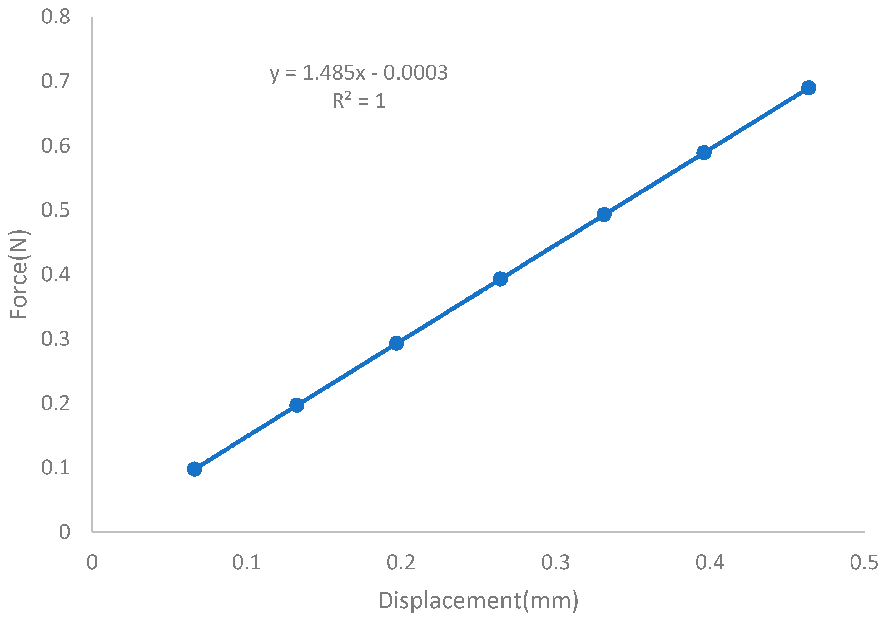
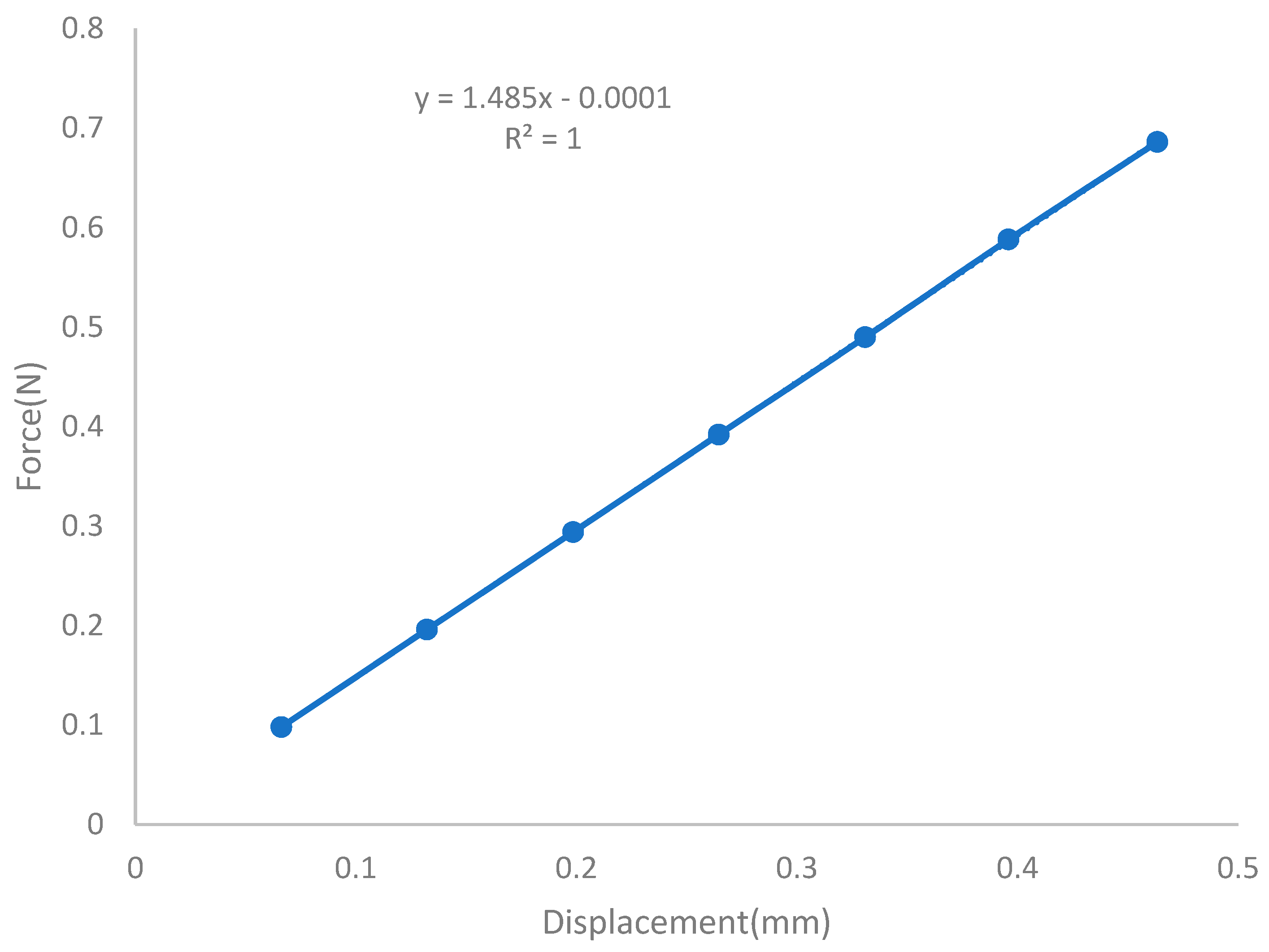
Based on the experimental and theoretical results shown in Table 4, a linear regression analysis of the force vs. the displacement was performed, indicating the spring constant of 1.485 N/mm in Figure 14 and Figure 15.

4.2. Spring Constant without VCA

To investigate the spring constant ( k ) of the cantilever beam, the same procedure applies as with the VCA case. However, experiments are conducted with different weights rather than the voltage to obtain the deflection values for the respective force; the deflection is detected by a laser-displacement sensor.
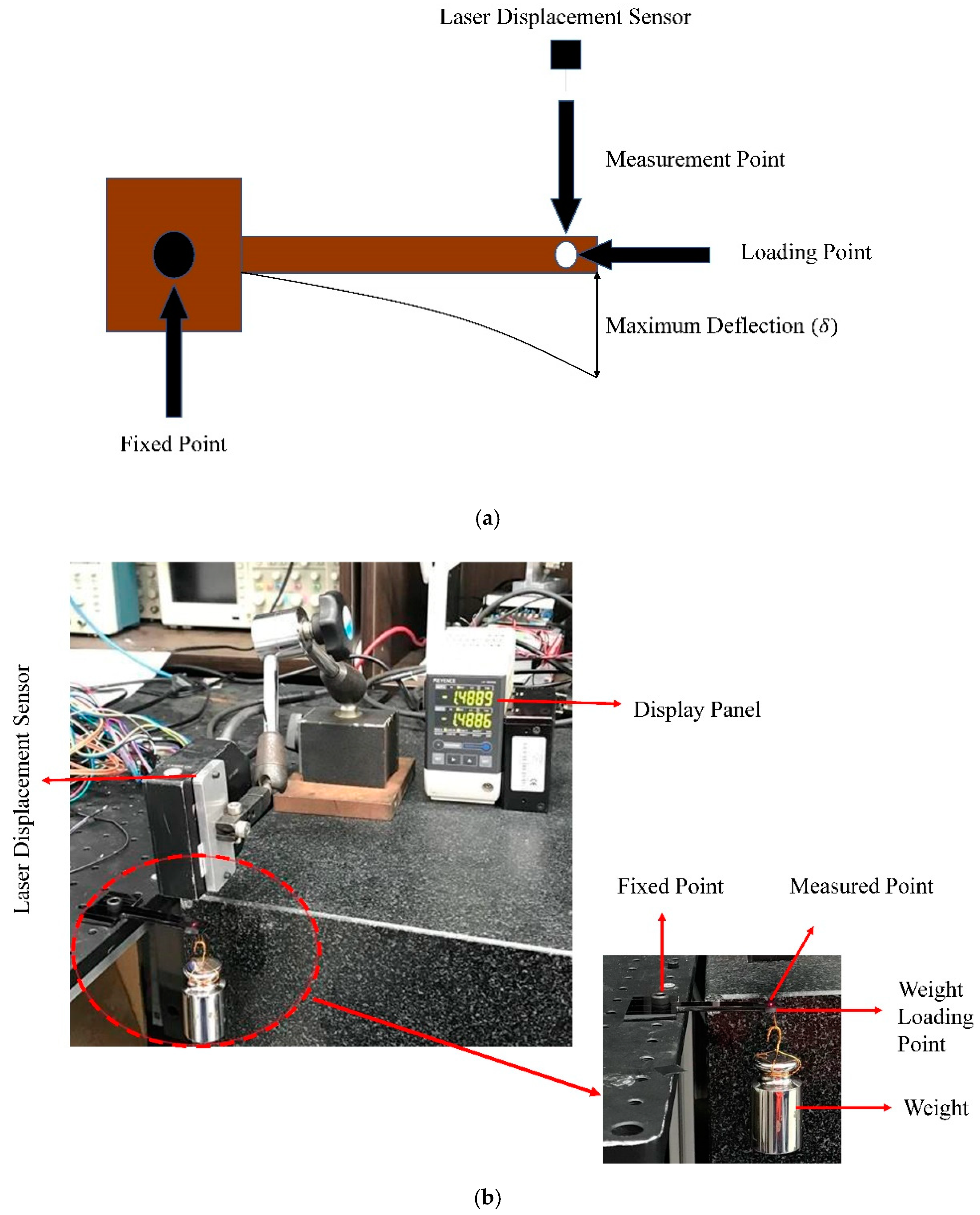
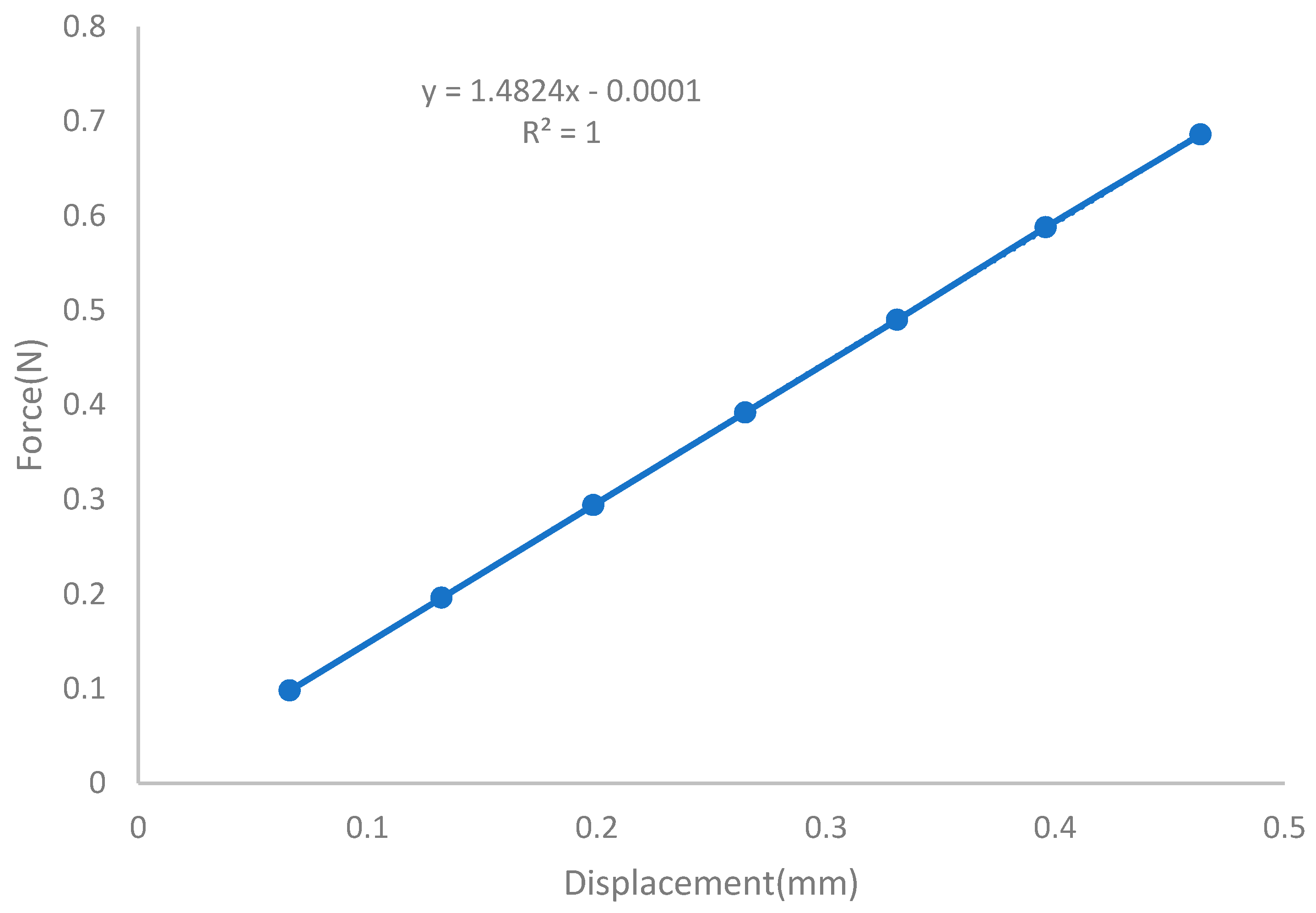
Figure 16 shows the experimental and schematic setup used to investigate the spring constant of the cantilever beam without the VCA; the deflections were recorded by a laser-displacement sensor. To perform these experiments, the cantilever beam was first designed using computer-aided design (CAD) modeling, then a physical shape was created to check its stiffness by fixing one end and applying weight and detecting the deflection using a laser-displacement sensor for a limit, not more than ± 0.5   mm . The display panel of the laser sensor was calibrated and the deflection for different weights was recorded. Table 5 summarizes the weight corresponding force and beam deflection for both the experimental and theoretical results. The graph shows the linear regression analysis using a spring constant of 1.485 N/mm.
For the theoretical stiffness of the plastic plate, we used beam deflection theory to calculate the maximum deflection of the plastic plate.
δ m a x = F L 3 3 E I I = b h 3 12
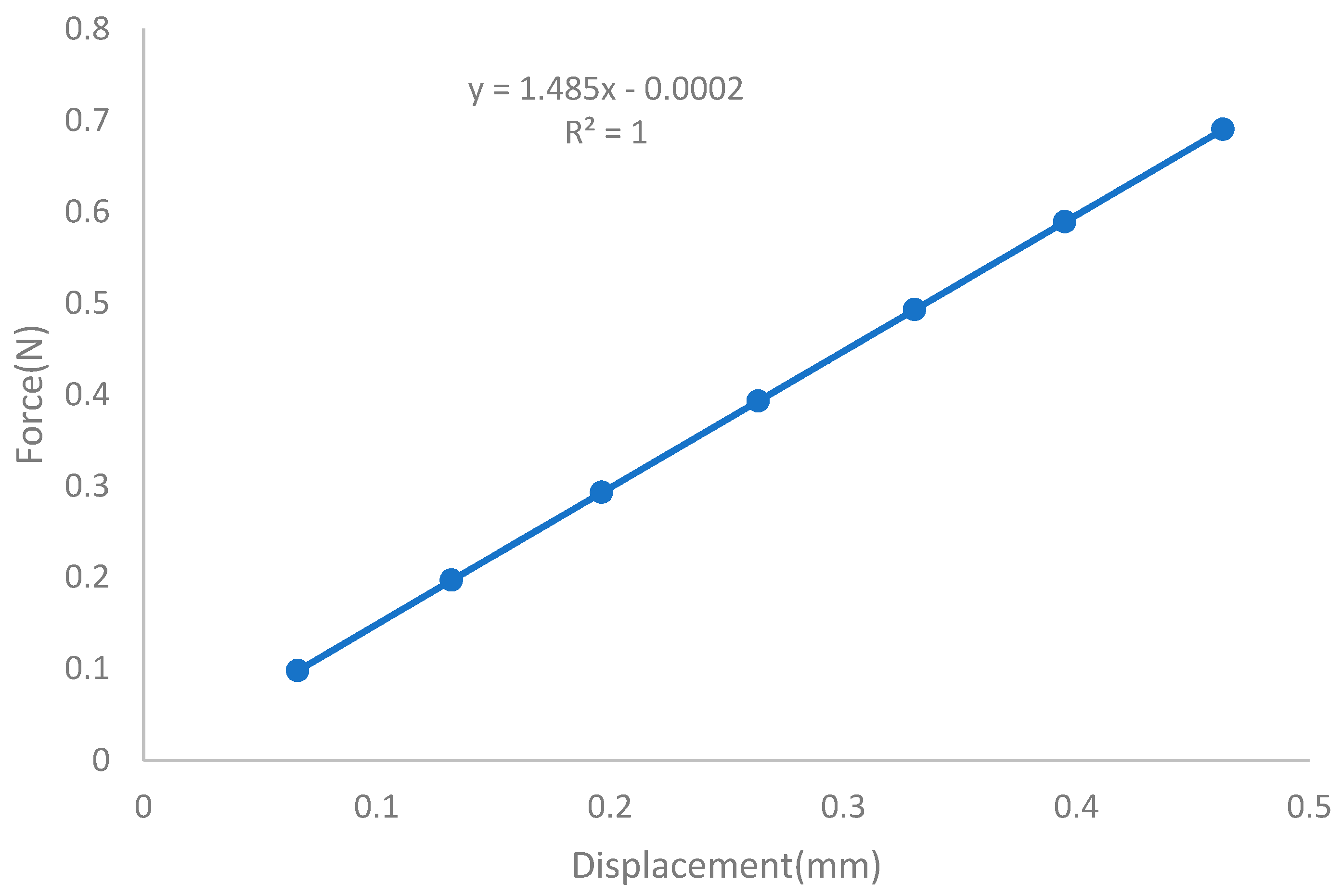
Based on both the experimental and theoretical results shown in Table 5, a linear regression analysis of force vs. displacement showed a spring constant of 1.485 N/mm in Figure 17 and Figure 18, respectively.

4.3. Equivalent Mass

Calculating the mass as one-third of the total mass of the beam at the free end, the system can be assumed as a discrete system as seen in Figure 19.
m = 33 100 × m b
m b = ρ V V = b d l
The volume was V = 1500   mm 3 and the density of the acrylic sheet 1.2 × 100 6   kg / mm 3 to obtain the beam mass m b = 0.018   kg . The lumped mass then became m = 0.00424   kg . Thus, the total mass with the end mass (bobbin) can be found as follows:
m = m + m b o b b i n m b o b b i n = 0.061   k g   ( A l u m i n u m ) ,   0.033   k g   ( P l a s t i c )
m = 0.0652   kg ( Aluminum ) m = 0.0372   kg ( Plastic )

4.4. Damping Coefficient

The damping coefficient is calculated by applying a step value of F V C A using NI Max to obtain the step responses with and without the VCA for the conductive (aluminum) and non-conductive material (plastic).
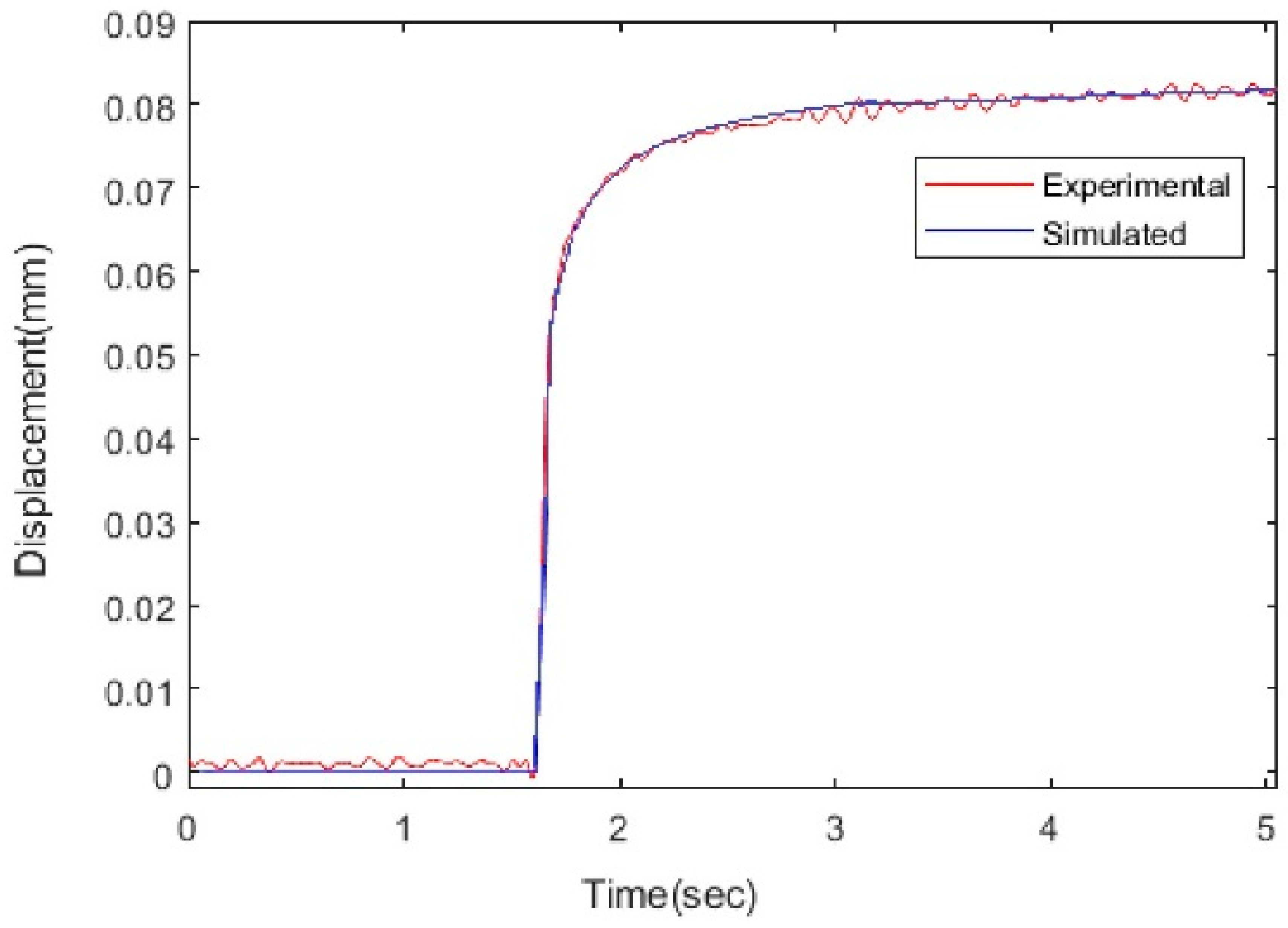
For the VCA with the conductive material, we provided step input using the LabVIEW algorithm; the damping coefficient could be identified through a comparison between the simulated response to a step input and the corresponding experimental response. With the step input of 21 mA for the VCA, the measured step response appeared over-damped, as shown in Figure 20a. To identify the damping coefficient, simulations were repeated with values of 0.2, 0.25, and 0.3; the results are also shown in Figure 20a. From a comparison with the experimental data, the best estimating damping coefficient was 0.25 N sec mm corresponding to a damping ratio of 0.401.
In contrast, for the non-conductive material case, the same procedure applied as for the conductive material case. The experimental responses with different values were compared by checking the damping coefficient with 0.02, 0.03, and 0.04; the system responded most adequately with 0.03   N sec mm , which corresponds to the damping ratio of 0.048, as shown in Figure 20b.
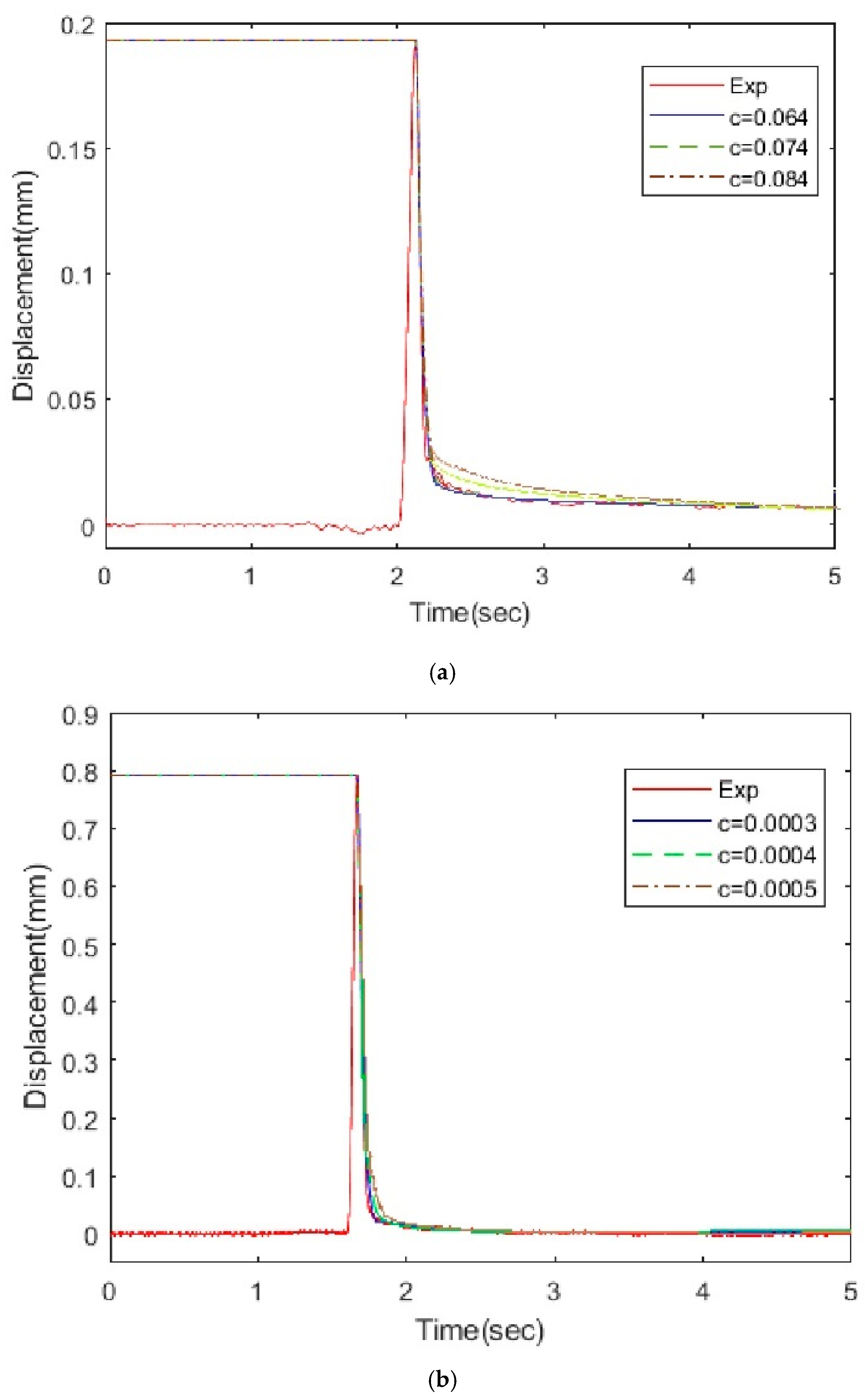
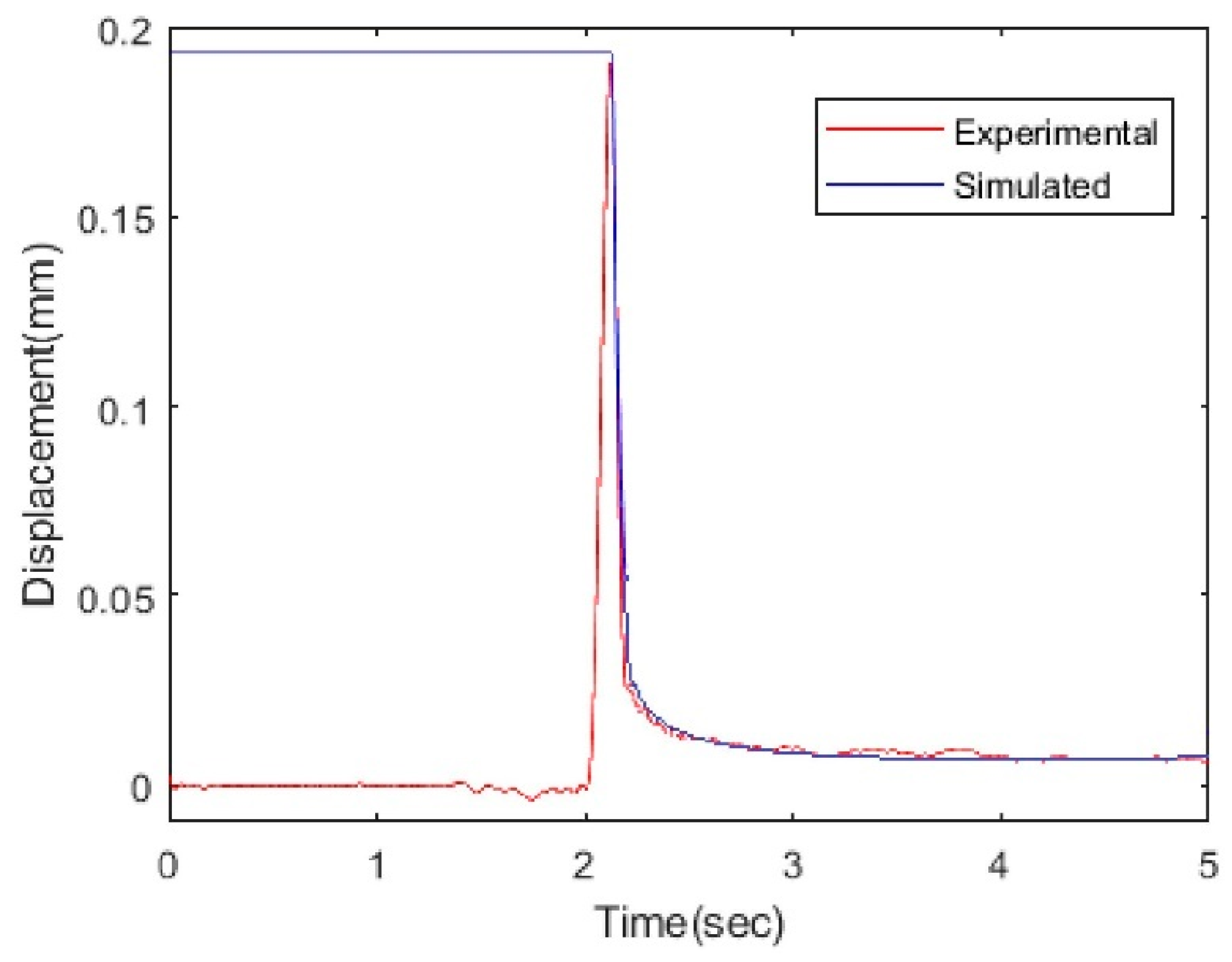
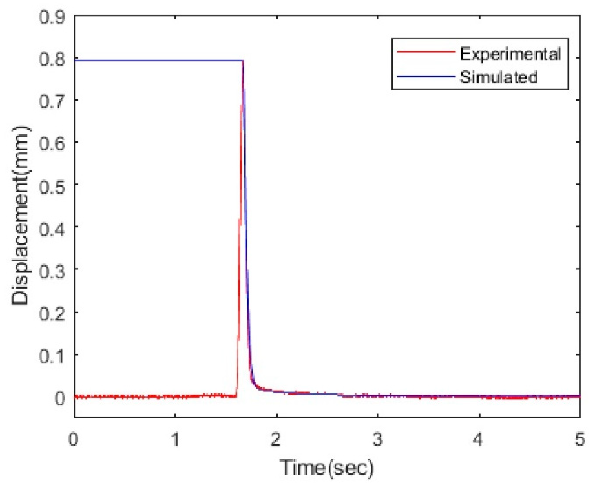
Similarly, without the VCA, the cantilever beam was pushed and released for the conductive and non-conductive material cases and a similar procedure was followed to compare the experimental results with the simulated results. The best-estimated damping coefficient o f   0.064 N sec mm with a corresponding damping ratio of 0.102 for the conductive material and 0.0004 N sec mm with a damping ratio of 0.00064 for the non-conductive material are shown in Figure 21b (right for the conductive material and left for the non-conductive material). Therefore, we concluded that it was also over-damped despite showing a fast time response.

5. Factors that Affect Performance of Voice-Coil Actuator

5.1. Effect of Electromagnetic Damping

To check the relationship between the step responses of the EMFC balancing scale and the input voltage to the VCA, several experiments were performed using different voltages to generate the necessary electromagnetic force to balance the scale. The electromagnetic damping force between the bobbin and permanent magnet plays a very important role by affecting the performance of the VCA. The parameters that affect the VCA are the eddy current density, magnetic flux density, volume of the conductive sheet, and relative velocity. However, material conductivity is the most significant of these.
Two different experiments were performed with and without the VCA. The first part of experiments used conductive material and the second part dealt with a non-conductive material to check the electromagnetic damping force.
To examine the electromagnetic damping force of the EMFC balancing scale for the conductive material, we constructed the same system as shown in Figure 12. To confirm the quantitative electromagnetic damping force, we performed two different experiments to determine this difference. For the first case, we used step input using the LabVIEW algorithm and NI Virtual Bench amplifying the input current to move a plate with an attached aluminum bobbin, and recorded the response using a laser-displacement sensor. For the second case, we performed experiments using a finger to push the beam and releasing it to record the impulse response corresponding to the impact we applied using a laser-displacement sensor as well.
For both cases, there was a difference in the damping coefficient; in the first case, there was more electromagnetic damping compared to the second case as it included the VCA. The damping coefficient in the VCA case is 5 times more than the case without it. The same procedure for the second part of experiments was performed, albeit with different materials, to see the difference of the responses; the electromagnetic damping force in the second case is almost zero with and without the VCA.

5.2. Effect of Material Conductivity

In the VCA for the conductive and non-conductive material cases, magnetic flux density was the most important factor, affecting the electromagnetic damping force and behavior of the VCA because of the relative speed between the bobbin acts as a conductor and the magnetic field is constant.
The coil magnetic flux density can be expressed as:
B = μ N . I π D ,
where N is the number of turns/windings in coil, I is the current flowing through the coil, D is the diameter of wound coil, and μ is the permeability of conductor (copper in our case). The magnetic flux density of a voice-coil actuator is determined using a magnet sensor. The maximum current flow in a coil is related to coil diameter, meaning that a large diameter coil requires a larger input current flow. Small diameter coils are damaged when applying high currents.
Core diameters as large as the coil diameter when winding the coil and magnetic flux density are smaller. When the coil length is larger, more coil turns are required to increase magnetic flux density. In our case, the space for mounting the coil to generate the magnetic field was limited. To design a VCA with a magnetic flux density in a given space, the larger the diameter of the coil, the larger the allowable maximum current value.
Therefore, the magnetic flux density can be increased but the number of coil turns is reduced leading to a decreased magnetic flux density. Similarly, the smaller the diameter, the smaller the allowable maximum current value; however, the number of windings can be increased to increase the magnetic flux density. The magnetic flux density is proportional to the magnitude of the windings diameter and coil diameter, as seen in Equation (17) and they are inversely proportional to the diameter of the winding.
Therefore, the VCA should be designed by finding the optimum value that gives the maximum magnetic flux density under constraints such as the space limit of the coil winding; we chose the best coil to obtain these properties.
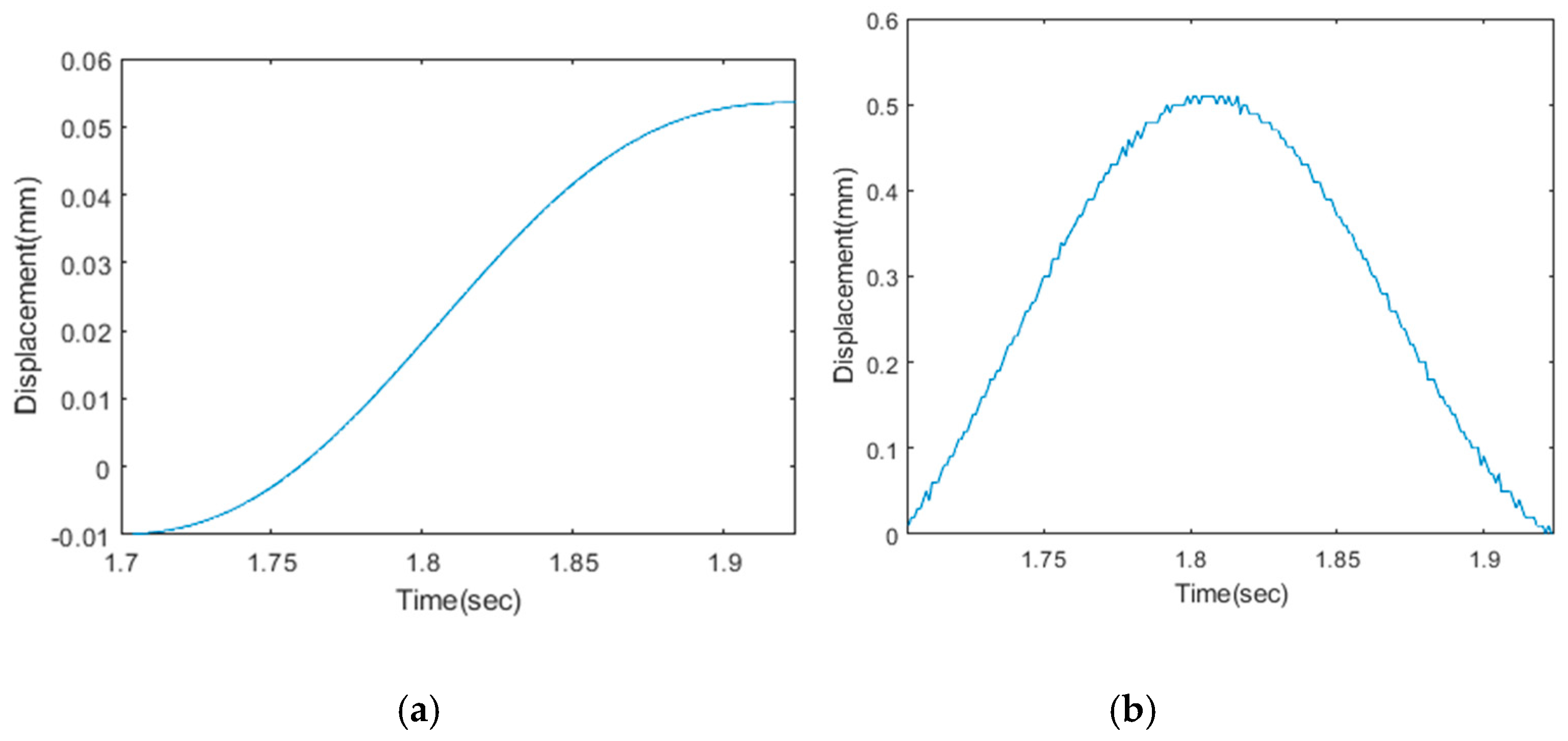
Table 6 shows the properties of the material used for the experiments when the specimen was conductive (aluminum) and non-conductive (plastic). Figure 22 shows the displacement and instantaneous velocity for the step input.

5.2.1. Electromagnetic Force with VCA for Both Materials

We used a bobbin made of conductive material (aluminum), which was attached to a plastic plate acting as a cantilever beam. Using the above setup in Figure 12 to obtain the behavior and step response for the different inputs with and without the VCA, we found that the response was over-damped, but that there was an electromagnetic damping force as seen in the previous section, which is a hurdle between the smooth time response that affects VCA overall performance as seen in Figure 23. Equation (3) is used to calculate the electromagnetic force, 3.148   N , as seen in Table 6.
The same experiment was conducted for non-conductive material (plastic) and the response is seen in Figure 24 with almost zero electromagnetic force.

5.2.2. Electromagnetic Force without VCA for Both Materials

For conductive material, we follow the same procedure to record the responses with and without the VCA. In these responses, when a conductive material is used, we can control the effect of the electromagnetic damping force, which is a barrier for the linearity and fast time response of the VCA. Figure 25 shows the recorded result from the step response.
For non-conductive material, the same experiments were performed by pushing the cantilever beam and recording the responses as seen in Figure 26.
In conclusion, for the results without the VCA force, both conductive and non-conductive materials had zero electromagnetic force because the current is directly proportional to the force, magnetic flux, and material conductivity.
According to the results obtained from the conductive and non-conductive materials, we concluded that if non-conductive material is used, we can obtain a smoother response and linear behavior than if conductive material is used.

6. Conclusions

It was determined based on the cantilever beam with an attached bobbin experiment, simulation and theoretical analyses, that preliminary electromagnetic damping tests with and without voice coil actuator using different materials for the bobbin, checking electromagnetic damping force and its impact on system performance, as well as the conductivity of the materials, all play an important role in achieving a fast time response. Furthermore, we obtained the following conclusions:
  • The cantilever beam with an attached bobbin acts as a conducting coil floating in a permanent magnet as the current is applied and the beam is returned to balance form by the EMFC, and not by applying any weight to balance the beam.
  • From theory and simulations, the system identification was confirmed, experimentally determining which had the best agreement in each case, that is, with and without the VCA.
  • The preliminary electromagnetic damping test was performed using step input current to record the step response with and without the VCA and by using different selected materials for the bobbin, namely, aluminum (conductor) and plastic (non-conductor). The electromagnetic damping force was more in the conductive case and less in the non-conductive case. Therefore, the non-conductive material was found to be the best choice to satisfy the fast time-response requirements; it also overcomes the electromagnetic damping by increasing the system performance.
  • The conductivity of the material plays an important role that is directly related to the magnetic flux of the material; therefore, we selected a large-diameter coil because small-diameter coils were damaged as we applied more current.
  • After conducting all the experiments, we concluded that a non-conductive material is best for our system and it will be applied to a balancing-type scale to improve the performance of the VCA.

Author Contributions

A. and J.-H.A. conceived and designed the experiments; A. performed the experiments; A., J.-H.A. and H.-Y.K. analyzed the data; A. wrote the paper. All authors have read and agreed to the published version of the manuscript.

Acknowledgments

The first author of this paper gratefully acknowledges support from the Institute for Research and Industry Cooperation (IRIC) Pusan National University (PNU) with the direction of Jung-Hwan Ahn from Research Center.

Conflicts of Interest

The authors declare no potential conflict of interest with respect to research, authorship, and/or publication of this article.

References

  1. Website Access Products. How do Balances and Scales Work? Available online: https://www.adamequipment.com/aeblog/how-do-balances-and-scales-work (accessed on 31 January 2020).
  2. Amthor, A.; Weiß, H.; Kaiser, I.; Rogge, N. Analysis, physically motivated modeling and system identification of electromagnetic force compensated balances (EMFC). Tech. Mess. 2015, 82, 393–401. [Google Scholar]
  3. Yamakawa, Y.; Yamazaki, T. Mathematical model of check-weigher with electromagnetic force balance system. Acta Imeko 2014, 3, 9. [Google Scholar] [CrossRef]
  4. Yamakawa, Y.; Yamazaki, T. Simplified Dynamic Model for High-Speed Checkweigher. Int. J. Mod. Phys. Conf. Ser. 2013, 24, 1360036. [Google Scholar] [CrossRef]
  5. Hwang, J.D.; Kwak, Y.K.; Jung, H.; Kim, S.H.; Ahn, J.H. Minimization of modeling error of the linear motion system with voice coil actuator. Int. J. Control Autom. Syst. 2008, 6, 54–61. [Google Scholar]
  6. Singh, R.; Sharma, M.; Singh, V.P. An experimental study of vibration control of cantilever beam using eddy current damper. Int. J. Appl. Eng. Res. 2012, 7, 1491–1496. [Google Scholar]
  7. Bae, J.S.; Hwang, J.H.; Park, J.S.; Kwag, D.G. Modeling and experiments on eddy current damping caused by a permanent magnet in a conductive tube. J. Mech. Sci. Technol. 2009, 23, 3024–3035. [Google Scholar] [CrossRef]
  8. Cheng, T.-H.; Oh, I.-K. Vibration suppression of beam by using magnet-coil. Model. Signal Process. Control Smart Struct. 2008, 6926, 692618. [Google Scholar]
  9. Bae, J.S.; Kwak, M.K.; Inman, D.J. Vibration suppression of a cantilever beam using eddy current damper. J. Sound Vib. 2005, 284, 805–824. [Google Scholar] [CrossRef]
  10. Matsuzaki, Y.; Ikeda, T.; Nae, A.; Sasaki, T. Electromagnetic forces for a new vibration control system: Experimental verification. Smart Mater. Struct. 2000, 9, 127–131. [Google Scholar] [CrossRef]
  11. Sodano, H.A.; Bae, J.S.; Inman, D.J.; Keith Belvin, W. Concept and model of eddy current damper for vibration suppression of a beam. J. Sound Vib. 2005, 288, 1177–1196. [Google Scholar] [CrossRef]
  12. Sodano, H.A.; Inman, D.J. Non-contact vibration control system employing an active eddy current damper. J. Sound Vib. 2007, 305, 596–613. [Google Scholar] [CrossRef]
Figure 1. Schematic outlines of electromagnetic force compensation (EMFC) balance-type scale.
Actuators 09 00008 g001
Figure 2. Experimental setup of force balance compensation-type scale.
Actuators 09 00008 g002
Figure 3. Electromagnetic damping principle.
Actuators 09 00008 g003
Figure 4. Setup to check electromagnetic damping for voice-coil actuator (VCA).
Actuators 09 00008 g004
Figure 5. Physical and mass-spring-damper system.
Actuators 09 00008 g005
Figure 6. Cantilever beam in magnetic field generated by permanent magnet.
Actuators 09 00008 g006
Figure 7. Schematic diagram of VCA.
Actuators 09 00008 g007
Figure 8. An equivalent RL circuit of VCA.
Actuators 09 00008 g008
Figure 9. Force vs. current.
Actuators 09 00008 g009
Figure 10. Variation of force (F) according to bobbin displacement from the center.
Actuators 09 00008 g010
Figure 11. Simulink model of voice coil actuator.
Actuators 09 00008 g011
Figure 12. Experimental setup.
Actuators 09 00008 g012
Figure 13. Experimental deflection of beam for different input currents.
Actuators 09 00008 g013
Figure 14. Experimental relationship between force and displacement.
Actuators 09 00008 g014
Figure 15. Theoretical relationship between force and displacement.
Actuators 09 00008 g015
Figure 16. Schematic outlines (a) and experimental setup (b).
Actuators 09 00008 g016
Figure 17. Experimental relationship between force and displacement.
Actuators 09 00008 g017
Figure 18. Theoretical relationship between force and displacement.
Actuators 09 00008 g018
Figure 19. Cantilever beam with attached mass (bobbin) with free vibration (lumped mass) (left) and rectangular cross-section of the beam (right).
Actuators 09 00008 g019
Figure 20. (a) Damping coefficient identification with VCA (conductive). (b) Damping coefficient identification with VCA (non-conductive).
Actuators 09 00008 g020
Figure 21. (a) Damping coefficient identification without VCA (conductive). (b) Damping coefficient identification without VCA (non-conductive).
Actuators 09 00008 g021
Figure 22. (a) Displacement according to step input and (b) instantaneous velocity according to displacement.
Actuators 09 00008 g022
Figure 23. Step response of conductive material with VCA.
Actuators 09 00008 g023
Figure 24. Step response of non-conductive material with VCA.
Actuators 09 00008 g024
Figure 25. Step response of conductive material without VCA.
Actuators 09 00008 g025
Figure 26. Step response of non-conductive material without VCA.
Actuators 09 00008 g026
Table 1. Physical and geometrical properties of the beam.
PropertyValue
Young Modulus of Cantilever Beam 2.76   Gpa
Density of Cantilever Beam 1.26 × 10 6   kg / mm
Thickness of Beam 3   mm
Length of Beam 50   mm
Width of Beam 30   mm
Depth of Beam 5   mm
Number of coil turns 300
Thickness of Copper Coil 0.2   mm
The conductivity of Copper Coil 607.6   Ω / m
Table 2. Experimental system specification.
ComponentsSpecificationValues
Model m ( kg ) 0.0652
c ( N sec mm ) (Aluminum)
c ( N sec mm ) (Plastic)
0.3
0.025
k ( N / mm ) 1.485
VCA R ( Ω ) 28.9
L ( mH ) 24.535
k f ( N / A ) 28.46
Z Total ( Ω ) 100
Table 3. Force–current relationship of VCA.
Current(mA)Force(N)
200.55917
401.13796
601.70694
802.29554
1002.85471
1203.44331
1404.00248
1605.58127
1805.14044
2005.71923
2206.26859
2406.85719
2607.41636
2807.98534
3008.54451
Table 4. Experimental and theoretical results of current related force and deflection with VCA.
Voltage
( V )
Current
( A )
Force
( N )
Laser Point Deflection
( m m )
Measured Values
Laser Point Deflection
( m m )
Theoretical Values
Loading Point Deflection
( m m )
Measured Values
Loading Point Deflection
( m m )
Theoretical Values
0.10.00340.0980.00910.00900.06630.0661
0.20.00690.1970.01830.018130.13250.1321
0.30.01030.2930.02720.026970.19700.1965
0.40.01380.3930.03670.036180.26430.2636
0.50.01730.4930.04620.045380.33150.3307
0.60.02070.5890.05510.054220.39610.3951
0.70.02420.6900.06420.063520.46400.4629
Table 5. Experimental and theoretical results of weight-related force and deflection without VCA.
Weight
( k g )
Force
( N )
Experimental Deflection ( mm ) Theoretical Deflection
( mm )
0.010.0980.06620.0661
0.020.1960.13220.1323
0.030.2940.19850.1985
0.040.3920.26450.2647
0.050.4900.33090.3309
0.060.5880.39580.3958
0.070.6860.46330.4633
Table 6. Electromagnetic damping force for two different materials.
PropertiesValues
Conductivity of Copper Coil 607.6   Ω / m
Magnetic Flux Density 0.425   Tesla
Length of Coil 75.241   m
Number of Turns 300
Thickness of Wire 0.2   mm
Permeability 16.675   N / A 2
Electrical Conductivity of Aluminum 3.5 × 10 7   Ω / m
Electrical Conductivity of Plastic 10 25 10 27   Ω / m
Relative Velocity 0.0002869   m / sec
Electromagnetic Force
(aluminum)
3.148   N
Electromagnetic Force
(Plastic)
0   N