1. Introduction
A probe station can be used to test the electrical performance of dies on a wafer by physically connecting a probe and a welding panel of a die on a wafer. Testing speed is a critical criterion in this process due to the 100% inspection requirement in mass production [
1,
2]. With the development of wafer processing technology, the wafer diameter gradually increases from 8 to 12 in. (20.32 to 30.48 cm). With the increasing die density and size of the wafer, precision probe stations with high speed and long travel length become high in demand [
3]. In a probe system, the motion servo system aligns every die on the wafer with the testing probe with a high frequency. To meet these requirements, development of high-performance actuators for motion servo systems becomes a key technical enabler. The existing servo drive mode can be divided into the electromagnetic drive and friction drive. In the application of the probe station, the electromagnetic actuator has the problem of precision caused by the machining accuracy and stiffness of the transmission system in the process of fast and precise positioning with frequent starts and stops. For example, in the linear motion servo system driven by a rotary servo motor, the machining accuracy of the screw rod is difficult to maintain with the increase in screw length. However, the travel range of the linear motor is not affected by other mechanical motion pairs [
4,
5,
6]. This research aims to design a linear motor for the electrical-performance detection probe station of 12 in. (30.48 cm) wafers, in which the density of dies in one line is more than 5 pcs per cm and the width of the welding panel is less than 10 micrometers. In this situation, the travel range of the motor should be more than 300 mm and the position precision under fast testing intervals should be less than the dimension of one welding panel. This work presents a linear ultrasonic motor that fulfills the above-mentioned requirements. With the inverse piezoelectric effect, a linear ultrasonic motor (LUSM) is able to transfer the periodical vibration of its piezoelectric ceramics to the unidirectional linear motion of a mover [
7]. The stator acting directly on the rotor makes it a compact structure. With the higher energy density compared with other types of electromagnetic motors, piezoelectric motors can be more easily miniaturized [
8,
9,
10,
11]. Besides, LUSMs are also featured by fast response speed, free from electromagnetic interference, and self-locking function. These advantages make LUSMs suitable for a wide range of applications in precision driving, aerospace, etc. [
12,
13,
14,
15].
According to the number of vibration modes during operation, LUSMs can be classified into single-mode LUSMs and dual-mode LUSMs. The construction of single-mode LUSMs is simpler than that of dual-mode ones [
16]. To change the motion direction of single-mode LUSMs, there are two well-known approaches. One is to excite a symmetric identical mode by switching exciting areas on the stator [
17]. In this way, the stator must be symmetrical. Another way is to excite a different vibration mode by varying exciting frequency. To achieve bidirectional motion with controllable performance parameters, such as speed and thrust, by vibration trajectories, dual-mode ones are better as the vibration trajectories of their contact points between the stator and mover are ellipses formed by the superposition of two orthogonal vibration modes [
18,
19,
20]. Synchronizations of the two vibration modes are very critical to the performance of the actuator [
21]. Therefore, the similarity of the frequencies is a key parameter for the LUSM design [
22,
23].
There are two typical types of dual-mode LUSMs according to the similarity between two vibration modes. Type 1 has two working modes with the same modal shape, while Type 2 has two different vibration modes [
24]. When two working modes are the same, the trajectory of the contact tip remains elliptical regardless of the assembly conditions. This is good for the consistency of performance along different motion directions [
16,
25,
26,
27]. However, when different working modes are applied, the structural parameters should be optimized to minimize the frequency difference between two working modes. In the authors’ previous work, a piezoelectric vibrator with two modes, the first-order bending vibration and second-order bending vibration, to form elliptical vibration of the driving tip is presented [
28]. Applying different working modes, the assembly conditions may affect the frequency consistency of two working modes [
29,
30]. Addressing this challenge is the motivation of the work presented in this paper.
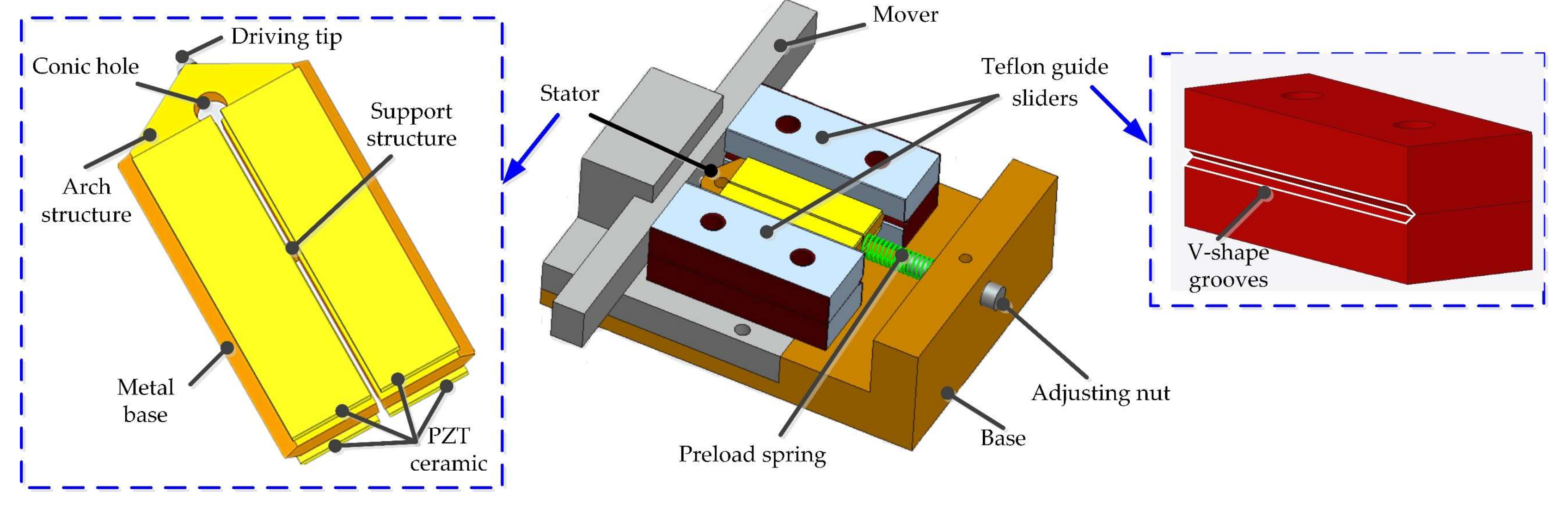
In this paper, an LUSM using two different working modes with the same local longitudinal vibration shape is proposed. As the two working modes are generated by the same local component behavior, the difference between two working modes is insignificant, and the impacts of the assembly on frequency are similar in both working modes, which are the advantages of this design. Besides, miniaturization has also been considered in this study by directly attaching the piezoelectric ceramics on the metal substrate [
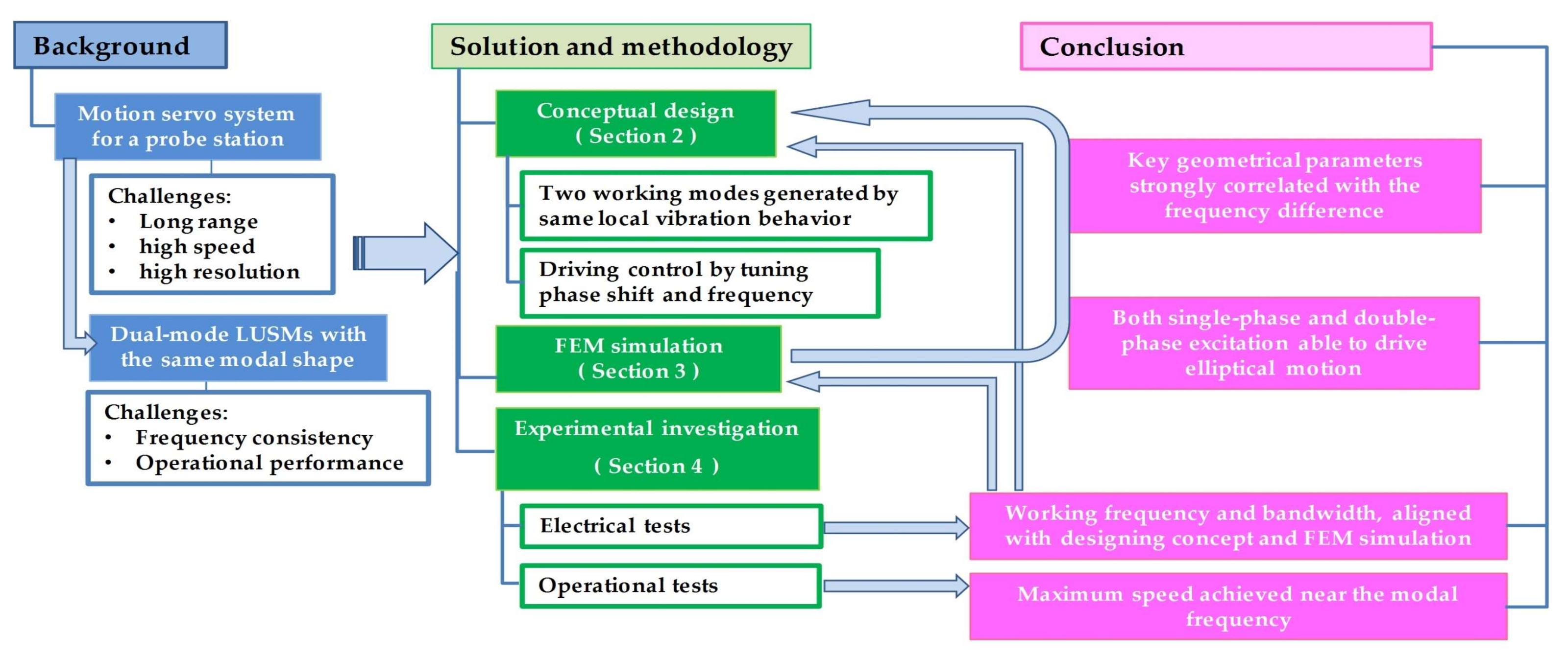
31]. The presented work can be illustrated by the graphical abstract shown in
Figure 1. In
Section 2, the conceptual design is introduced, and the FEM simulation is introduced in
Section 3. The experimental investigation is introduced in
Section 4, which validates the working principle and numerical simulation results.
3. Simulation Via FEM
To analyze the dynamic performance of the stator, its finite element model was established utilizing the commercial finite element software ANSYS. The material of the metal base is phosphor-bronze with a density of 8800 g/mm
3, Young’s modulus of 113 GPa, and Poisson’s ratio of 0.33. The physical parameters of the piezoelectric ceramics are listed as below:
where
e is the piezoelectric constant matrix,
εS is the dielectric constant matrix, and
cE is the stiffness matrix.
3.1. Modal Analysis
The geometric parameters are shown in
Figure 7. The dimensions of the piezoelectric ceramics are length 30 mm, width 8 mm, and thickness 1 mm. In the finite element model, two assumptions were made. One was to ignore the influence of the adhesive layers between the piezoelectric ceramics and the stator base, and bonding interfaces were used to simulate the connections between them. The other was to replace the wear-resistant ceramic ball at the driving tip with a sharp angle structure. The optimized stator structural parameters are shown in
Table 1.
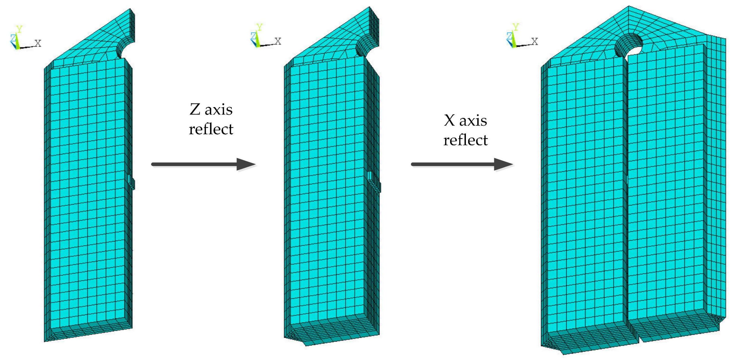
As the stator had two symmetric planes, a quarter of the stator was built first. In the finite element model, the solid5 element and mapping method were used to mesh the geometry of the piezoelectric ceramic part, and the solid45 element and sweeping method were used for meshing the geometry of the metal part. A quarter of the meshed stator model was reflected twice by two symmetric planes of the stator, and a complete stator finite element model was built, which is shown in
Figure 8.
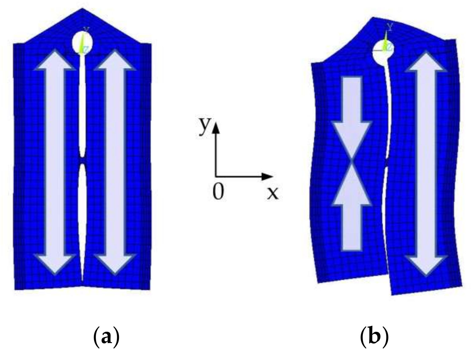
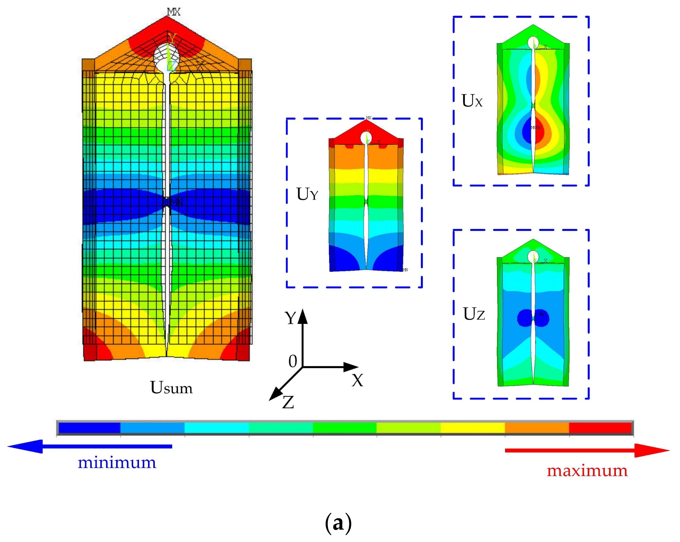
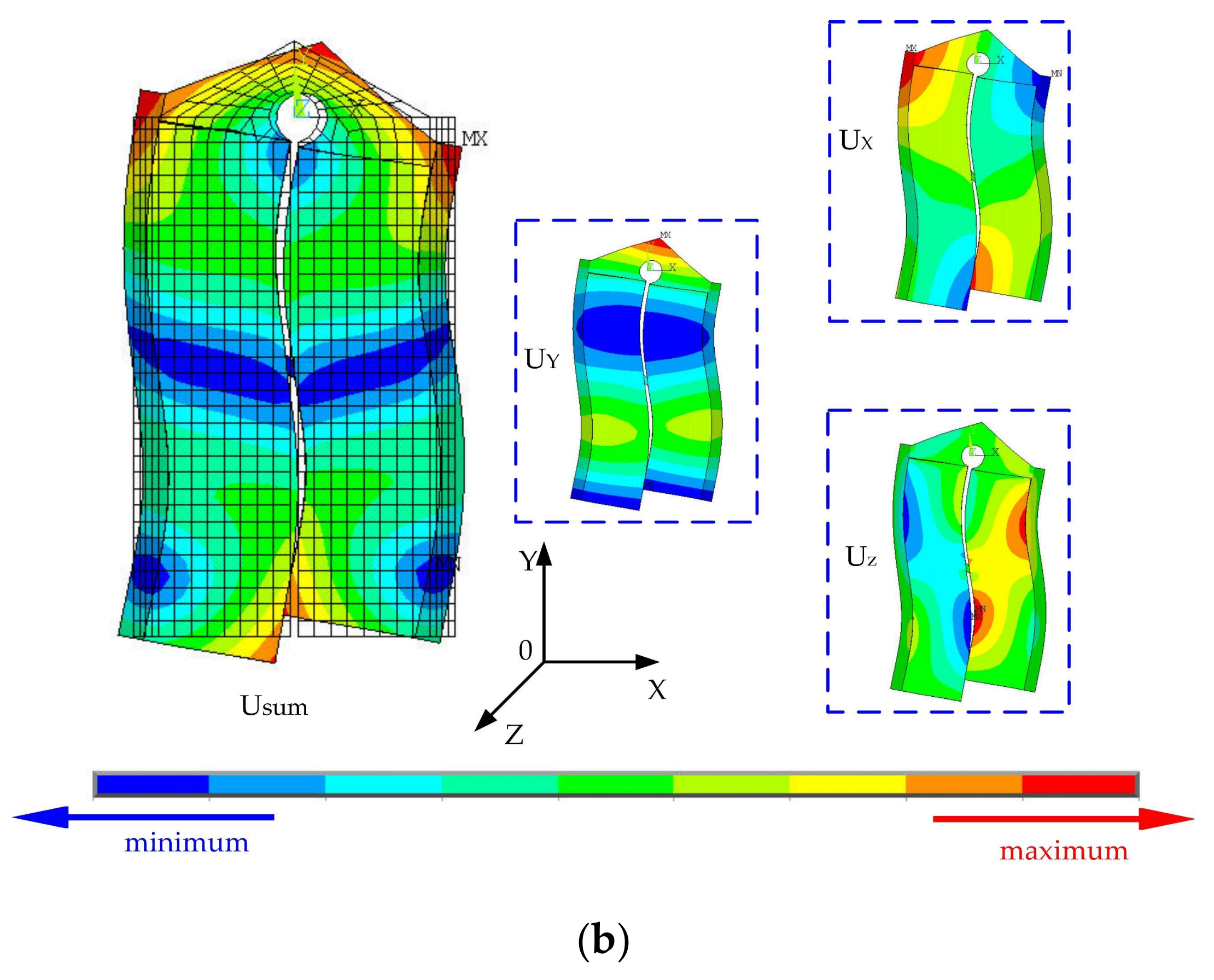
Modal analysis based on the finite element model was conducted, and the boundary condition was set to mechanical-free. The potential of the piezoelectric ceramic substrate was zero. Two working modes of the stator were built and the modal frequencies of the symmetric mode and anti-symmetric mode were 55,225 and 55,833 Hz, respectively, and the frequency difference between the two working modes was 608 Hz, as shown in
Figure 9. In the symmetric mode, the maximum displacement of the stator was along the
y-axis, and in the anti-symmetric mode, the maximum displacement of the stator was along the
x-axis.
3.2. Sensitivity Analysis of Geometrical Parameters
Sensitivity analysis is established to quantitatively describe the influence of the geometrical parameters of the stator on the frequency difference between the two modes. The modal frequencies of both working modes vary with the geometric parameters. The sensitivity of the two modal frequencies to geometrical parameters can be formulated as:
In the above formula, the sensitivities Ssj are determined by the partial derivative of modal frequency fsj to geometrical parameter Pj. As the exact functional relationship between modal frequency and the geometrical parameter is not clear, the sensitivity could be approximately calculated by the ratio of the frequency difference caused by the variation in geometrical parameter ΔPj to ΔPj During the manufacturing process of the stator, the value of sensitivity is guidance for designing the tolerance of the geometrical dimension.
The sensitivity of modal frequency difference to structural parameters is
where
fsj and
fasj are the modal frequencies of the symmetrical and anti-symmetrical modes, respectively,
fsjv and
fsj0 are the modal frequencies of the symmetrical modes after and before the variation in geometrical parameter
Pj, respectively, and
fasjv,
fasj0 are those of the anti-symmetrical mode, respectively [
32].
With the same finite element model introduced in
Section 3.1, increments were applied to the geometrical parameters with the same percentage, and the sensitivities of frequency difference to each geometrical parameter were obtained.
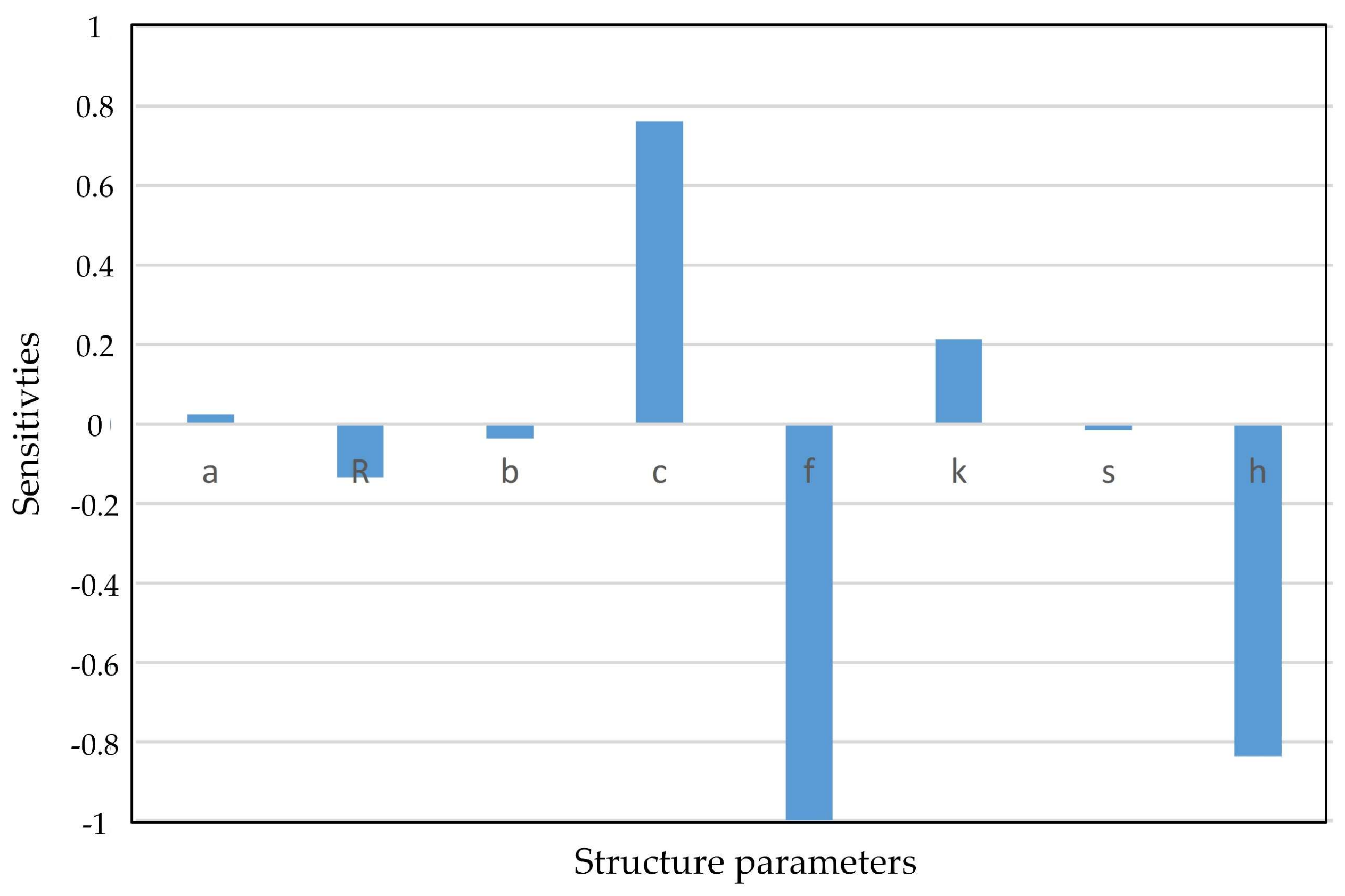
Figure 10 shows the normalized sensitivities values.
Figure 10 shows that the geometrical parameters
c,
f, and
h are more influential than the others. The parameter
c is the position of the supporting structure between two piezoelectric vibrators, which prevents the deformation of the arch structure, and its position should be near the nodal plane of both longitudinal vibrators. On the other hand, these three parameters could be utilized for adjusting the frequency difference of the working modes.
In the dynamic performance simulation of the stator, sensitivity analysis offered efficient directions for decreasing the frequency difference of the two working modes by varying the geometrical parameters with bigger sensitivity values. As the working modes were generated by the same local longitudinal mode, the designed stator had two working modes with nearly the same frequencies. This way of composing the ultrasonic motor can be utilized to design dual-mode LUSMs with small modal frequency differences. In this dual-mode motor composed by two equivalent longitudinal vibration modes, three main geometrical parameters were greatly relevant with the frequency difference. They were the gap between two vibrators, the location of the connection, and the arch structure. By tuning the values of these three parameters, the geometrical parameters of the stator can be defined with a small modal frequency difference.
3.3. Harmonic Analysis
To verify the working principle introduced in
Section 2.2, harmonic analysis based on the finite element model was conducted by applying a voltage signal to piezoelectric ceramics. The harmonic analysis was conducted in two steps.
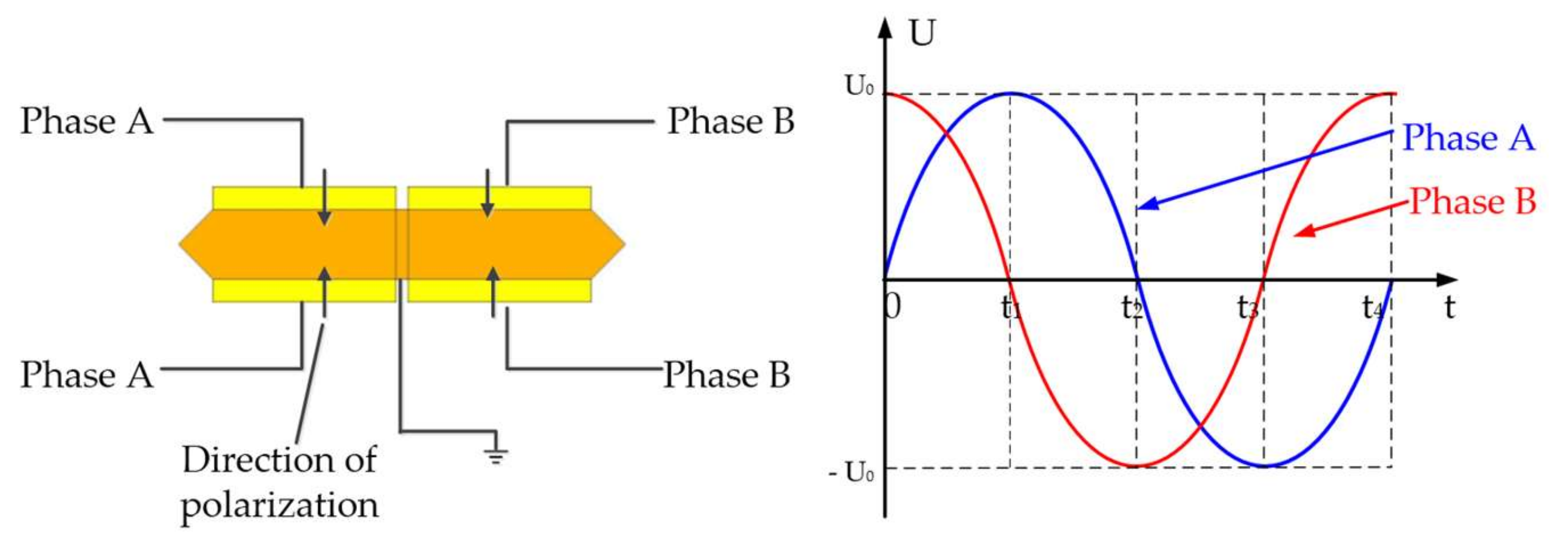
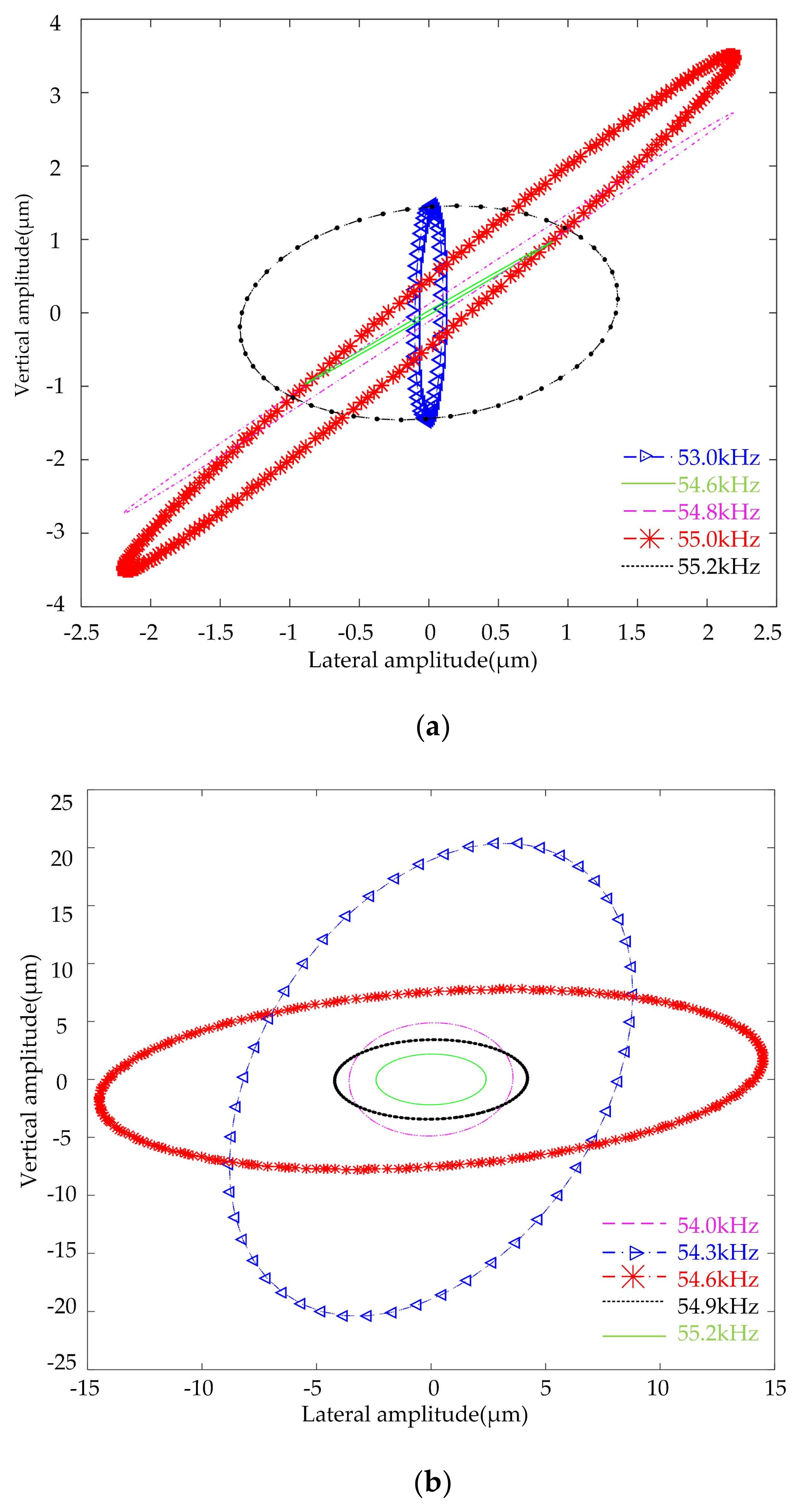
In step 1, a voltage signal was applied to the Phase-A terminal, while the Phase-B terminal was left open. When the amplitude of a voltage signal has a peak-to-peak value of 200 V, the vibration response of the driving tip under different frequencies near the modal frequencies is shown in
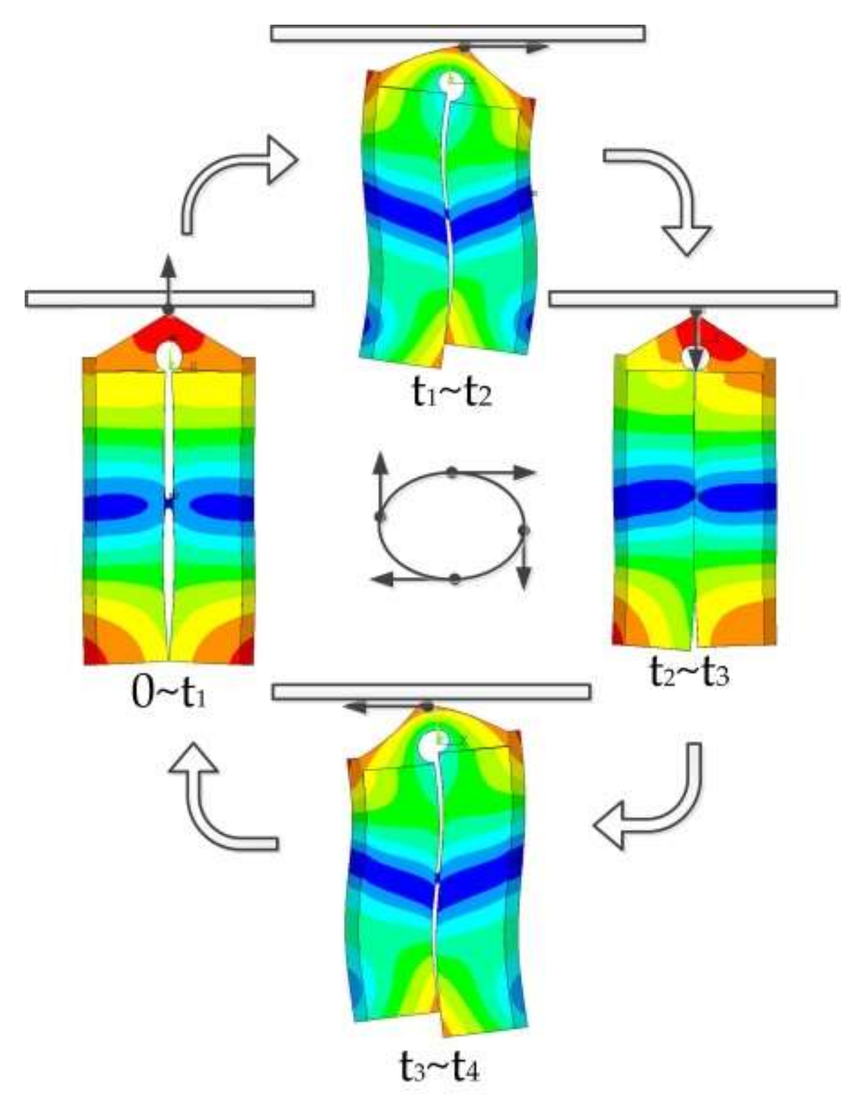
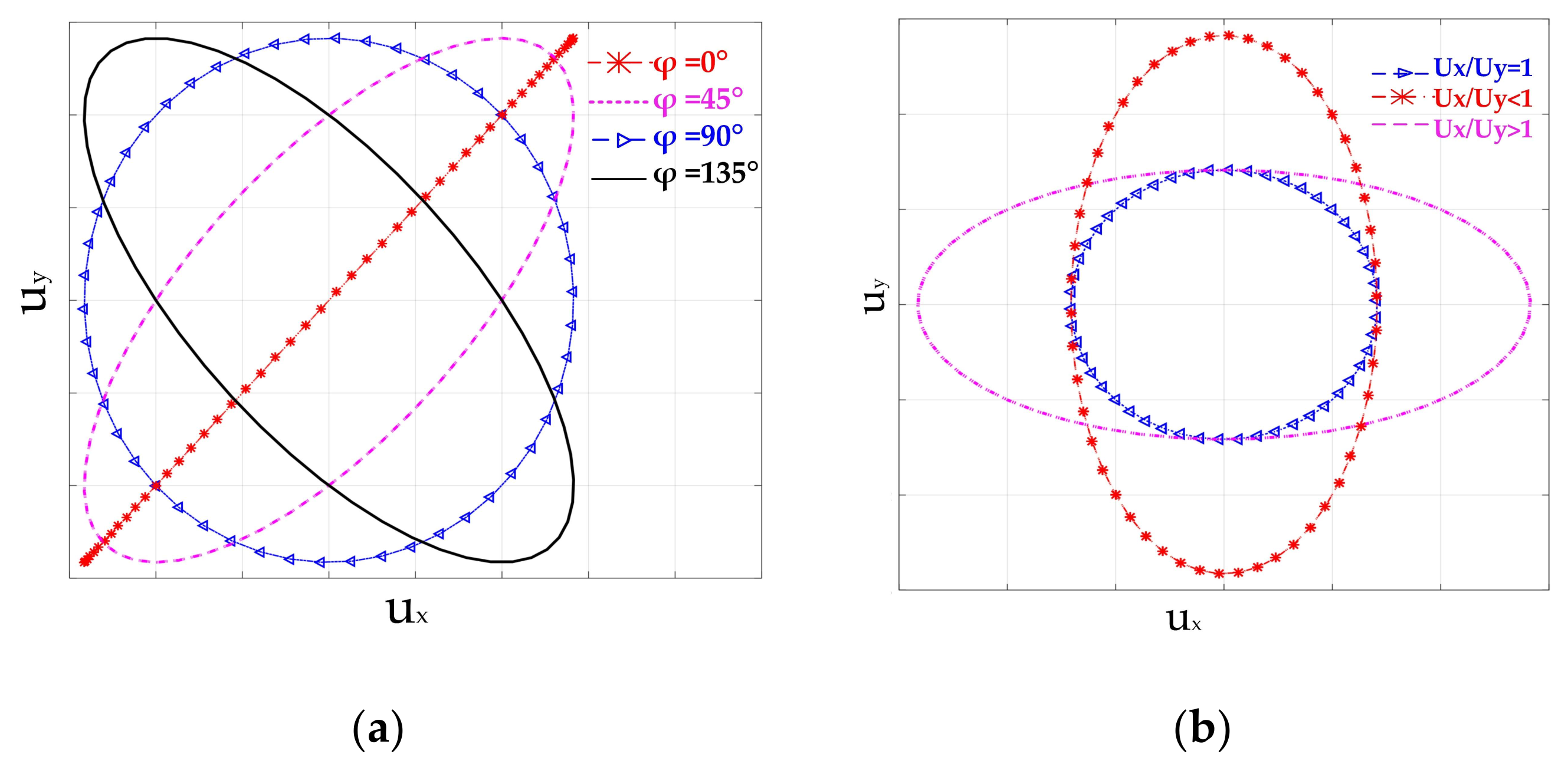
Figure 11a. It is shown that the vibration trajectories are ellipses with different orientations and radii. This phenomenon can be explained by modal superposition theory. The vibration response can be interpreted as the superposition of two working modes. As the amplitude and phase response of the two modes are different under different exciting frequencies, the vibration trajectories of driving tips vary with the exciting frequencies. A smaller phase shift between two modal responses results in a slimmer ellipse.
In step 2, two voltage signals with a phase shift of π/2 and an amplitude of 100 V were respectively applied to Phase-A and Phase-B terminals. As shown in
Figure 11b, the trajectories under different exciting frequencies were elliptical, which verified the principle analyzed in
Section 2.2. The orientations and sizes of these ellipses varied with the exciting frequencies, which determined both the phase shift and the amplitude.
From the harmonic analysis of the finite element model, the simulation results were aligned with the theoretical analysis. Both results have shown that the elliptical motion of the driving tip can be formed not only by dual-phase excitation but also by single-phase excitation. This phenomenon can be utilized to simplify the exciting power source by reducing the channels of exciting signals.
4. Experimental Investigation
Beside the FEM simulation, in order to further verify the proposed concept, a prototype was built based on the concept introduced in
Section 2. Four PZT8 piezoelectric ceramic plates were glued onto the surface of the stator with epoxy, solidified under 70 °C with a preload. Modal testing of the stator and measurement of the operational speed were conducted to assess its performance.
4.1. Impedance Analysis
Based on classic resonance theory, when the frequency of the external exciting voltage signal is close to the resonant frequency of piezoelectric ceramics, mechanical resonance will occur. The vibrational amplitude of the stator in the resonance state will be maximized. Meanwhile, its electrical performance near the resonance frequency can be analyzed by simplifying it into an equivalent electrical circuit. The modal frequencies of the stator are also close to the resonance frequencies of the equivalent electrical circuit. By measuring the impedance of the prototype, the relation between electrical characteristics and frequency can be obtained [
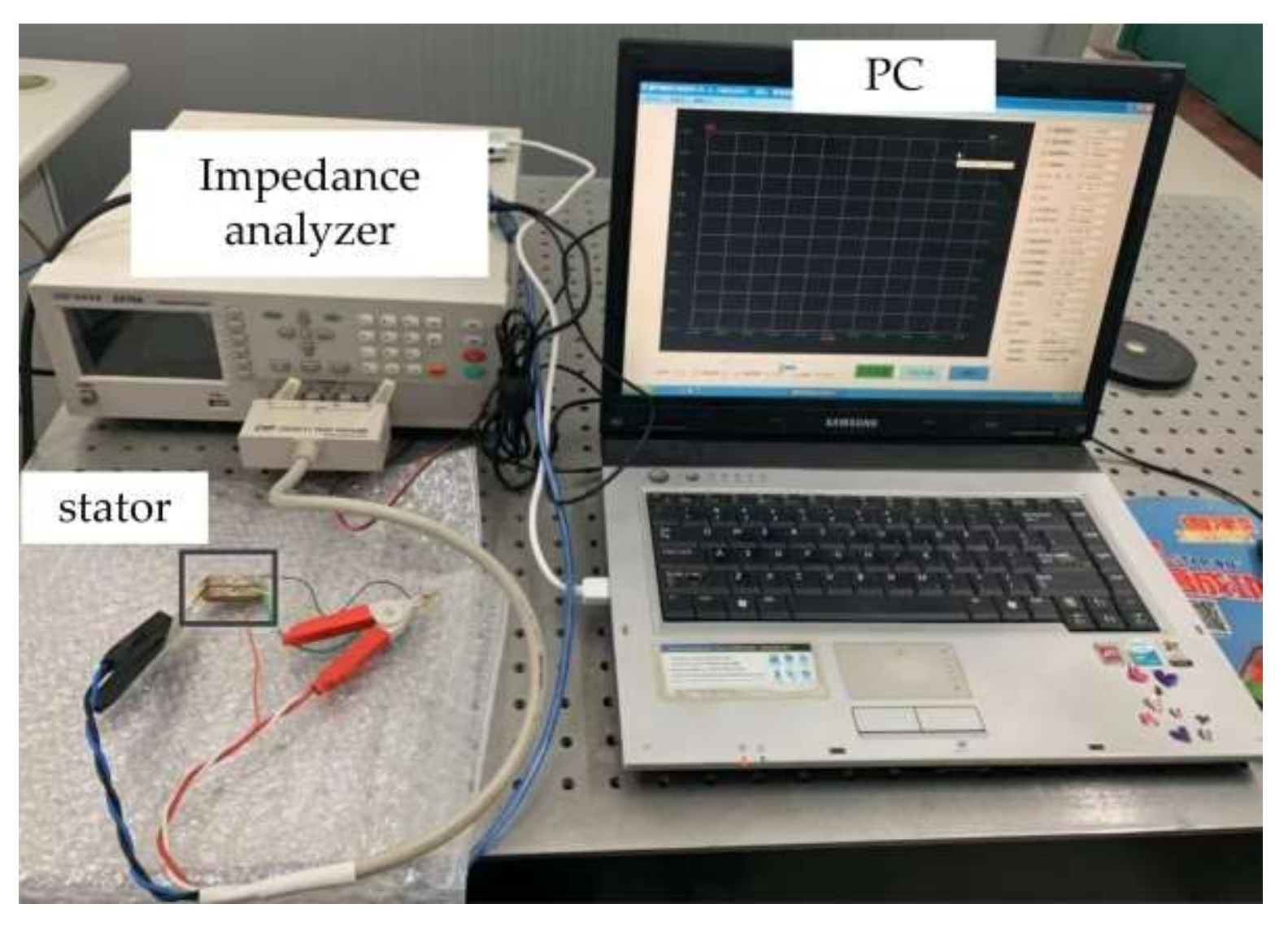
33]. In this study, an impedance analyzer ZX70A was used for the impedance test. The basic accuracy of the impedance analyzer was 0.05%, and the frequency accuracy was 1 mHz. As shown in
Figure 12, the stator was tested by the impedance analyzer with one phase connected to the impedance analyzer and the other one short-circuited. The frequency range was set from 52 to 60 kHz and the number of scanning points to 200.
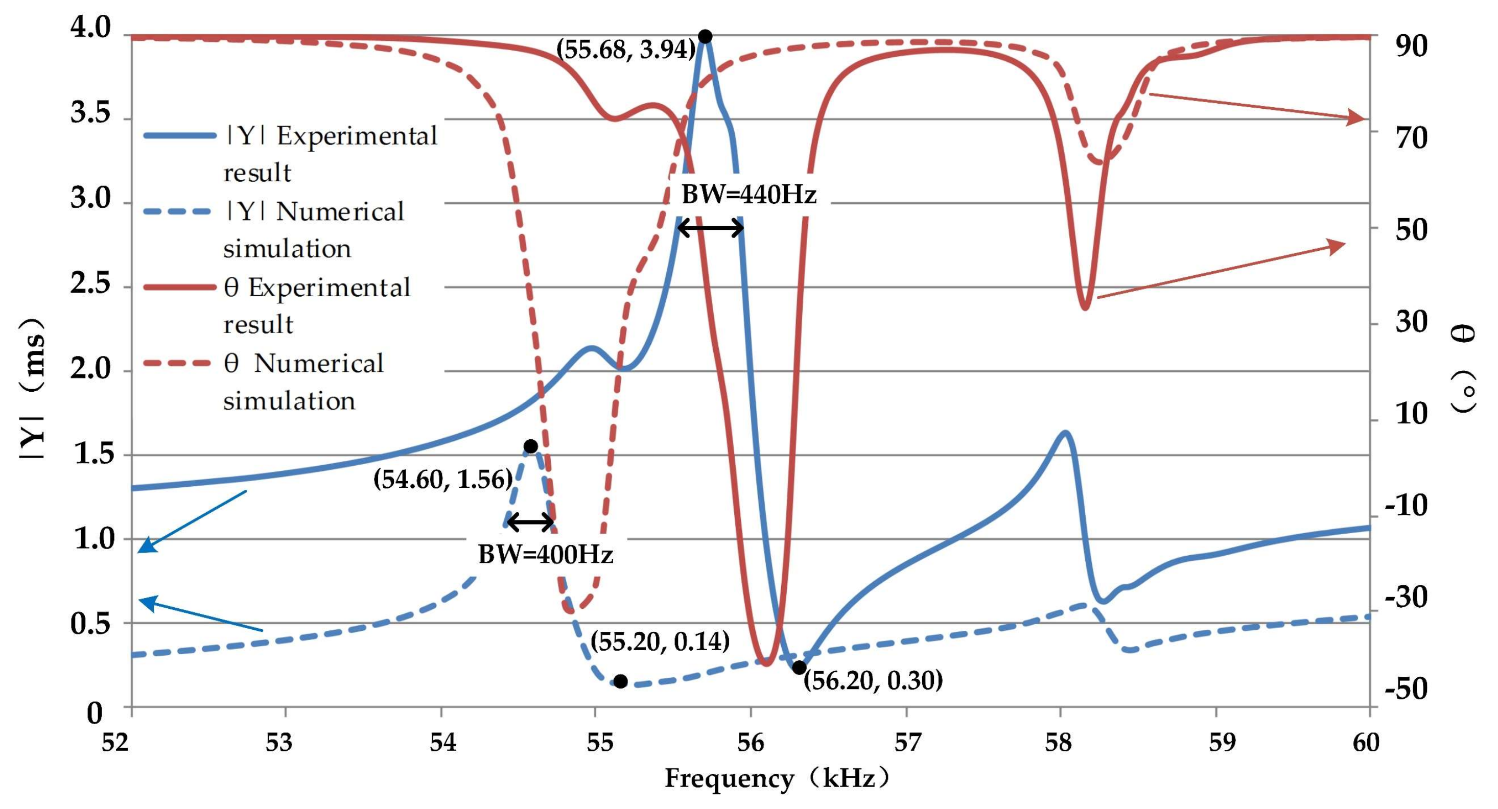
Figure 13 shows the comparison of impedance measurement results and that of ANSYS finite element impedance analysis with the built model.
It can be seen from
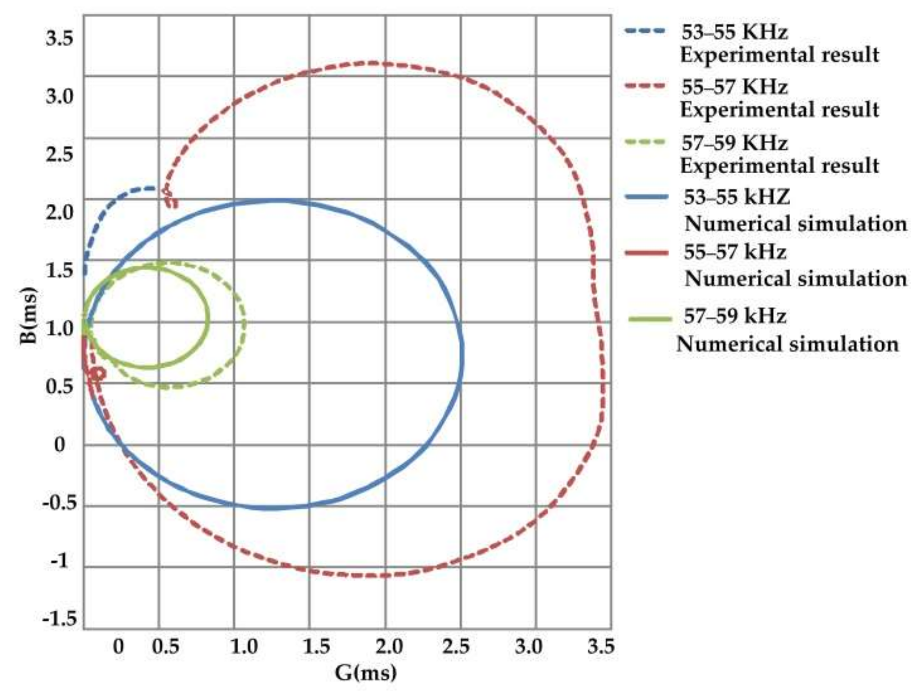
Figure 13 that both the numerical simulation and the impedance experiment have two resonant frequencies, and the higher admittance mode values are the working frequencies, which are 54.60 and 55.68 kHz, respectively. The relative error between them is 1.94%. The peak value of the admittance amplitude obtained by the experiment is 2.38 m/s. In the low-frequency band, the frequency of BW (bandwidth) obtained by the experiment is 440 Hz, and the frequency of bandwidth obtained by the numerical simulation is 400 Hz. Compared with the simulation results, it was found that the resonance frequency of impedance test results was higher than that of the simulation results. In order to show the impedance characteristics of the stator near the resonance frequency intuitively, the admittance circles of the three frequency bands are plotted in
Figure 14. From the figure, it can be concluded that there are corresponding admittance circles in both model simulation and prototype testing, which verifies the finite element model.
The admittance analysis results of the finite element model were verified by experimental tests. There was a deviation between the two results. This difference arose by the assumptions made in the finite element model. First, in the model, the connections between the metal elastomer and piezoelectric ceramics of the stator were taken as surfaces with shared nodes, without considering the influence of the adhesive layer between them. As the stiffness of the adhesive layer was different from that between the metal elastomer and piezoelectric ceramic, the electrical performance of the stator was practically determined by the adhesive layer. Secondly, the actual driving foot of the prototype was spherical colloidal contact and the mass of the whole stator was reduced due to the installation of a ball-shaped ceramic head at the driving tip, which was not considered in the finite element simulation. Thirdly, geometric tolerance existed in the stator manufacturing process, and the processing technology also had an impact on the material properties.
4.2. Operational Testing
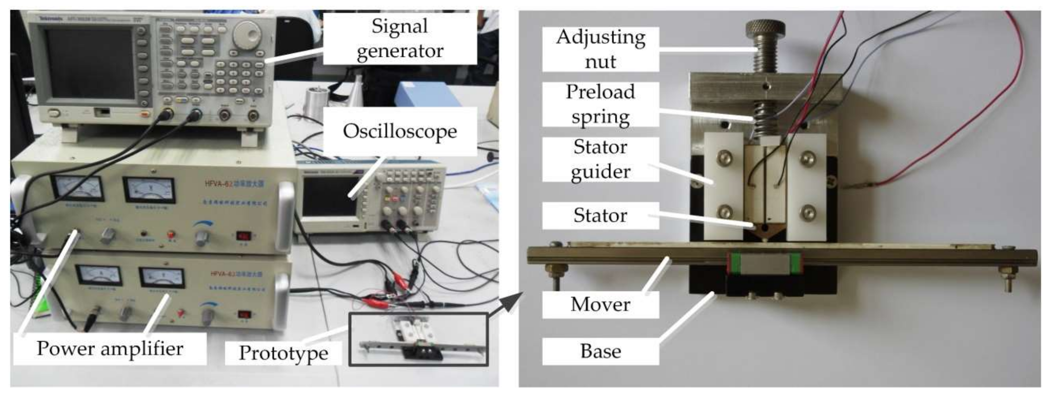
Based on the results of the simulation, a prototype of the motor for mechanical performance evaluation was developed.
Figure 15 (also shown in
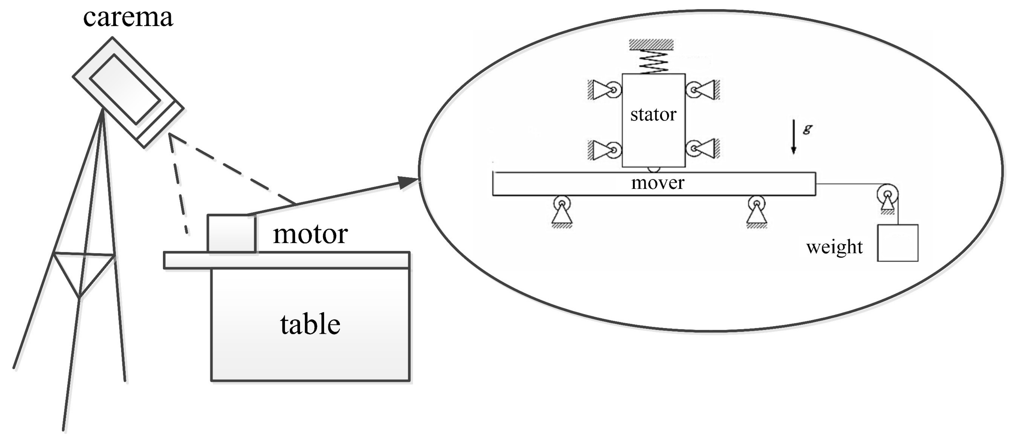
Supplementary Materials S1) shows its experimental setup. It consisted of two power amplifiers, a dual-channel signal generator, and an ultrasonic motor. In the experiment, the signal generator sent out two chord-wave signals with the same frequency and amplitude, and a phase shift of π/2. These two signals were amplified with a voltage peak-to-peak of 200 V and applied to the ultrasonic motor. The travel distance of the mover was 150 mm and the preload force applied on the stator was 30 N. The average velocity was measured by the time displacement method, and the measuring system is shown in
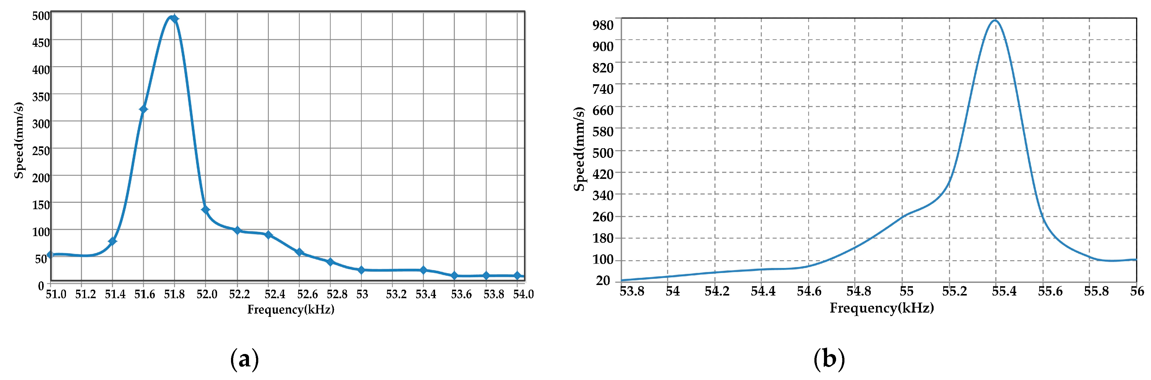
Figure 16. Then, the relationship between the speed and frequency can be established, as shown in
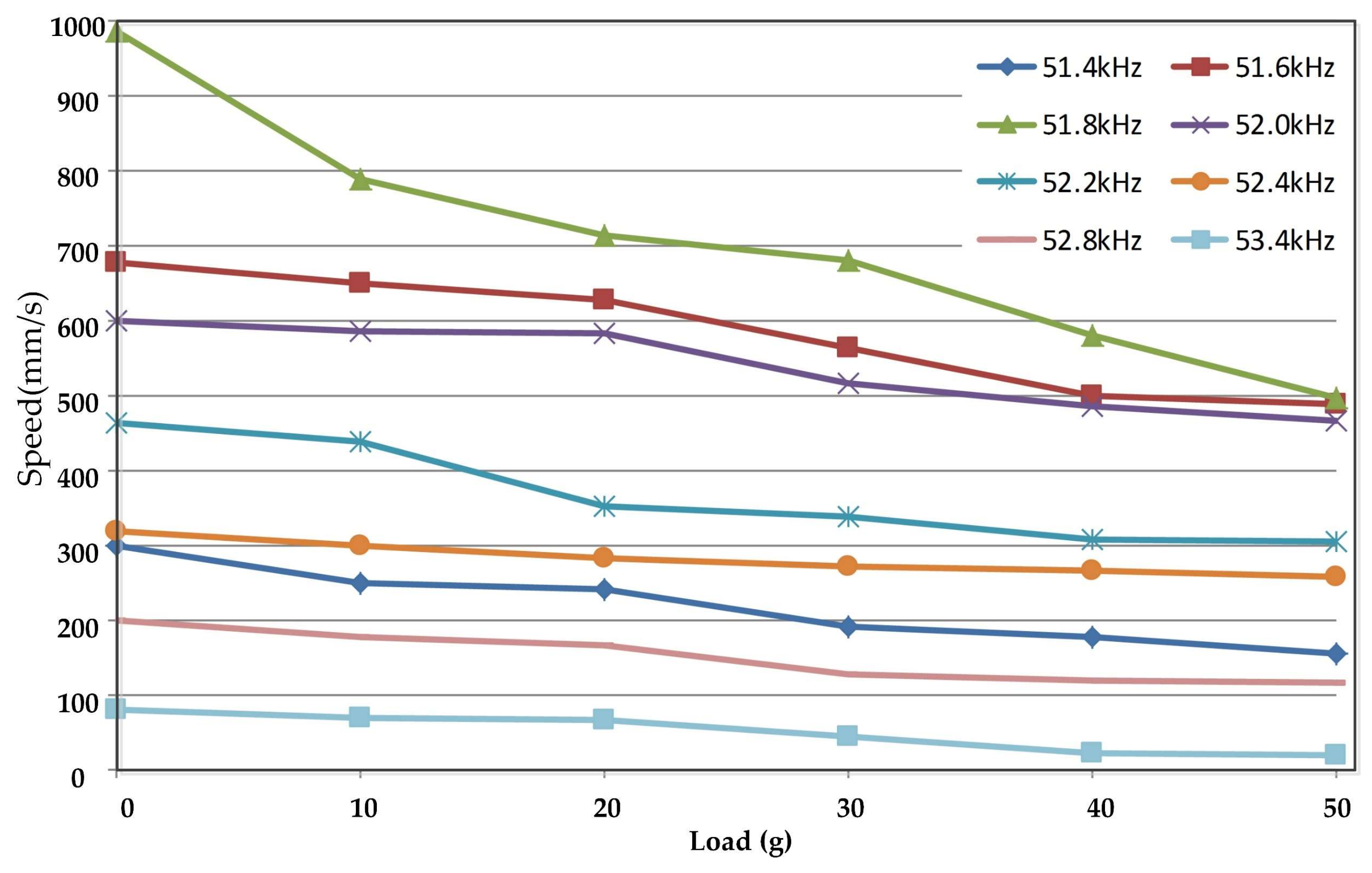
Figure 17. The load characteristic curves at different frequencies were also obtained, as shown in
Figure 18.
It can be seen that the maximum velocity of 488 mm/s can be obtained at the frequency of 51.8 kHz with single-phase excitation and 980 mm/s at the frequency of 55.4 kHz with dual-phase excitation. The relative error of the two resonant frequencies is 6.5%, which is an acceptable error. The motor under both excitation modes operates with the same vibration modes, but the vibration trajectories are formed differently. The mode of operation with dual-phase excitation is the superposition of two single-phase excitations with a phase difference in time. The operational test results showed that the motor was running well when the exciting frequency was near the modal frequency both in single-phase and dual-phase excitation, and it was able to reach the maximum speed when the exciting frequency was close to the modal frequency. It had a good load characteristic near the modal frequency, and the maximum holding force of the motor was 1 N.
5. Conclusions and Discussion
In the wafer inspection process, high resolution, long travel range, and high speed are highly demanded when designing the probe station. In this paper, a motion control system by an LUSM was proposed. The construction and operation principles were analyzed. The criteria of composing the stator were formed, which utilized the same local mode to compose low-frequency difference motors. On the basis of modal superposition theory, the vibration trajectory of the harmonic response was analyzed. By sketching the trajectories under different situations, it was found that even with single-phase excitation, the formation of elliptical vibration was possible. The prototype was fabricated based on the proposed concept. Both FEM and experimental results showed respectable performance, which were aligned well with the theoretical analysis. In addition, the trajectory of the dual-mode motor was fully studied in this paper, which provides a guideline for a controlling strategy.


