Article

Position Control with ADRC for a Hydrostatic Double-Cylinder Actuator

Jiangsu Province Key Laboratory of Aerospace Power System, College of Energy and Power Engineering, Nanjing University of Aeronautics and Astronautics, 29 Yudao St., Qinhuai Dist., Nanjing 210016, China
*
Author to whom correspondence should be addressed.
Actuators 2020, 9(4), 112; https://doi.org/10.3390/act9040112
Submission received: 30 September 2020 / Revised: 2 November 2020 / Accepted: 5 November 2020 / Published: 9 November 2020
(This article belongs to the Section High Torque/Power Density Actuators)

Abstract

:
A compact and flexible hydraulic double-cylinder actuation scheme is proposed for use in applications, especially where power density is extremely demanding. In view of flexible amounting requirements, long and thin hoses were utilized to connect two cylinders. Affecting the actuation preciseness, volume variation of the hoses caused by pressurized oil and bubbles was the main problem the system encountered. In this study, an active disturbance rejection control (ADRC) strategy was adopted for the improvement of displacement control performance under uncertain external load. After the experimental verification of the necessity of a hose model for the system, a centralized-parameter hose model was constructed where the coefficients are determined on the basis of the experimental data. Additionally, the system and the controller proposed were mathematically modeled. Simulation results shows that the system using ADRC exhibited higher displacement accuracy and better dynamic performance than that using PID (Proportion-Integral-Derivative) or fuzzy PID. ADRC has a stronger disturbance rejection ability. ADRC is an effective solution to nonlinear control of systems with uncertain parameters or various loads.

1. Introduction

Due to small size, light weight, fast response and high accuracy, the electrohydraulic servo system has been widely used in many fields such as aerospace, robot, construction industry, etc. [1,2]. At present, hydraulic actuation mainly includes valve-controlled and pump-controlled schemes. The valve-controlled system has been widely used in engineering fields owing to its high response frequency and power-to-weight ratio [3]. Pump-controlled EHA (Electrohydrostatic Actuator) provides a sleeker and cleaner way to produce hydraulic power with higher energy efficiency [4,5]. However, hydraulic actuators used in aerospace are inevitably strict in size and weight. They involve an oil supply source, which is a weight burden. A hydraulic actuation system without an oil source is obviously advantageous in aerospace application.
To break through the restriction, alternative methods have been investigated to affordably improve system efficiency. Minava presented a direct-driven hydraulic system without conventional oil source [6], which combined advantages of power density of hydraulic system and accuracy of electric motor system, and studied the application of direct-driven hydraulic device in trackless mobile machinery. A speed and position control system using double cylinders adopted a hydraulic accumulator instead of conventional oil tank, and an electric motor was used to achieve closed-loop control [7]. Effects of different parameters on dynamic characteristics of hose were examined. The smaller the hose flow diameter is, the more sensitive the volume variation to the pressure is [8]. Therefore, it is extremely necessary to model the hose in small-size and high-pressure displacement control systems.
Many research studies on position control of the electrohydraulic actuator were conducted, some of which reveal how external and internal nonlinear factors affect the control accuracy and system robustness [9,10]. Due to simple structure and easy implementation, PID control has been commonly used in hydraulic systems [9,10]. On this basis, some researchers developed accurate fuzzy PID and PSO-PID controllers [11,12,13,14]. A robust fixed-gain linear output pressure controller was designed for a double-rod electrohydrostatic actuator using quantitative feedback theory (QFT) to provide desired transient responses, tracking bandwidth, robust stability, and disturbance rejection for the closed-loop system [15]. Erik used model predictive control to eliminate the influence of feedback controller performance and to integrate both actuator limitations and other necessary constraints on dynamic wheel-load variation and suspension travel [16]. A nonlinear PI position controller was developed for the EHA to achieve the accurate positioning requirement of position-based impedance control (PBIC). The controller compensated for the adverse effect of stiction, and a high position accuracy was attained [3]. A novel sliding mode control (SMC) design framework was devoted to providing a favorable SMC design solution for the position tracking control of electrohydrostatic actuation system (EHSAS). The chattering was effectively attenuated, and the mismatched disturbance was satisfyingly compensated [17]. A novel discrete-valued model predictive control (DVMPC) algorithm was proposed for position control of a pneumatic cylinder [18]. A linear extended state observer (LESO) was adopted to achieve real-time estimation of the unmeasured system states and matched disturbance, and a nonlinear disturbance observer (NDO) was used to estimate the largely unknown mismatched disturbance at the same time [19]. All of the above concluded that a good control strategy is critical to the stability and robustness of position control.
ADRC is not predicated on an accurate and detailed dynamic model of a plant, and is extremely tolerant to uncertainties [20,21,22]. At present, ADRC has been applied in many fields, including artificial blood pumps, air-fuel ratio control in gasoline engines, airship horizontal trajectory tracking control, PV (Photovoltaic)-wind energy conversion system and aircraft electro-mechanical actuators [23,24,25,26]. The robotic system was represented as a linear perturbed system whose lumped disturbance input is estimated and then compensated by an extended state observer-based control [20]. ADRC has attracted attention and application in position control.
In this study, an electric motor was used as the original power component for hydraulic actuator without an oil tank. The motor rotates the ball screw, which pushes the power cylinder to pressurize the oil between the two cylinders and then moves the target cylinder. Considering installation and maintenance for an extremely narrow space, the slender hose was employed to connect these two cylinders for the flexibility required. Expansion of the hose induced nonlinear displacement of the cylinder. This paper focuses on the active disturbance rejection control strategy for a hydrostatic double-cylinder actuator, which was systematically analyzed and compared with the conventional PID and fuzzy PID strategy. Then, advantages of ADRC are verified. ADRC consists of a tracking differentiator (TD), extended state observer (ESO) and nonlinear state error feedback control law (NLSEF). TD achieves smooth approximation to the generalized derivative of input signals. ESO estimates the output and the total real-time perturbation. NLSEF uses the total perturbation observed by the ESO to generate the control variables, so as to ensure the stability of the system. This can provide a theoretical basis for ADRC application in double-cylinder hydraulic actuators. Section 2 describes the principle and mathematical model of the system. An ADRC strategy was designed. In Section 3, the results are revealed. Concluding remarks are presented in Section 4.

2. System Principle and Mathematical Model

2.1. System Principle

Figure 1 is a schematic diagram of the double-cylinder actuator. The electric motor rotates according to a pulse input and its angular displacement is transformed into linear displacement by a ball screw. The power cylinder pressurizes the oil in one chamber to push the target cylinder forward. A transducer is arranged to measure the displacement of the target cylinder. If these two cylinders are identical, their motions are theoretically synchronous. Actually, due to the deformation of the pressurized chamber, it is ineluctable for the cylinder leakage and the oil bulk modulus change caused by pressure or air. Size of the target cylinder can be designed as small as possible to be accommodated in designated space. In order to investigate the system performance under possible loads, an electrohydraulic system was fabricated as external load simulator. It mainly consisted of oil source, a proportional servo valve, a loading cylinder and a force transducer. A force closed-loop circuit ensured production of the required load exerted on the target cylinder. The flexible hose connection between two cylinders allows the system to be suitable for narrow space, and it can separate the target cylinder from the driving and control part for flexible assembly and disassembly. Moreover, the oil source was removed, simplifying the system structure greatly.

2.2. System Mathematical Model

The hose was one of primary factors affecting the actuator performance. It was modeled by the centralized parameter method [27], and the pressure and the flow rate in the hose can be equivalent to the voltage and current in electric circuit. The model based on this method is shown in Figure 2. Here R and L stand for the resistance and the inertia of the oil, respectively, and C describes the characteristic of the pressurized oil and the hose deformation.
C ( p p ) = q q
Generally, the hose has much larger expansion than the pipe if filled with high pressure oil. When modeling the hose, both the static and dynamic variation caused by the pressure and the viscoelasticity of the hose material are considered. Thus, C cannot be reckoned as a constant. Figure 3 illustrates the schematic considering the viscoelasticity of the hose.
Ratio of Δp to Δy is related by
Δ p Δ y = k · G ( s )
where
1 k = 1 k 1 + 1 k 2 + 1 k h
k h = 2 β e / a
G ( s ) = T 1 s + 1 T 2 s + 1
T 1 = B e k 2 T 2 = B e k 2 + k 1 k 2 / ( k 1 + k )
Here, p is the pressure inside the hose, y is the radius variation of the hose, kh is the equivalent coefficient of the oil compression converted into elastic deformation of the hose, k1 and k2 are the elastic coefficients of the hose and Be is the damping coefficient of the hose wall. a is the average radius of the hose.
Increment of the flow rate Δ q can be written as
Δ q = ( π ( a + Δ y ) 2 π a 2 ) l = ( 2 π a Δ y + π Δ y 2 ) l
where l is the length of the hose. Neglecting π Δ y 2 , Equation (7) is simplified as
Δ q = 2 π a Δ y l = 2 π a l Δ p k · G ( s )
C can be expressed as
C = 2 π a l k · G ( s )
Here, effects of the cylinder mass, leakage and oil temperature on the system are not considered. The pressure in two cylinders is assumed to be equal. Flow rate continuity for the actuation cylinder is given by
A P 1 X ˙ pi A A 1 X ˙ po = C P ˙
A A 2 X ˙ po A P 2 X ˙ pi = C P ˙ 2
As shown in Figure 1, AP1 and AP2 are the effective area of the power cylinder, AA1 and AA2 are the effective area of the target cylinder respectively. Xpi and Xpo are the displacements of the power cylinder and the target cylinder, respectively. Vh1 is the pressurized volume enclosed by the hose connecting two rodless chambers and Vh2 is the one enclosed by the hose connecting two rod chambers.
The kinematic equation of the system is written as
m X ¨ po = A A 1 P 1 A A 2 P 2 F f v
where Ft is the force as the external load, m is the load mass, P1 and P2 are the pressure of the rod chamber and the rodless chamber of the target cylinder respectively, and fv is the friction in the target cylinder as given by
f v = A A 1 P 1 A A 2 P 2 F , X ˙ po = 0 f s + μ visc X ˙ po , X ˙ po 0
where fs is the maximum static friction and μvisc is the viscous friction coefficient.
V ˙ h 1 and V ˙ h 2 are obtained by Equation (1) as
V ˙ h 1 = C P ˙ 1 V ˙ h 2 = C P ˙ 2
Based on Equation (10) to Equation (14), the mathematical model of the actuator system is established as
m X ¨ po = A A 1 P 1 A A 2 P 2 F f v A P 1 X ˙ pi A A 1 X ˙ po = C P ˙ 1 A A 2 X ˙ po A P 2 X ˙ pi = C P ˙ 2
In order to evaluate the effects of the hose model qualitatively, the open-loop simulation results (taking input = 0.5 m/s and F = 200 N) of the system with and without hose model are shown in Figure 4. It implies that the target cylinder displacement and the pressure in the rodless chamber with hose exhibits longer response lag during the system starts up.

2.3. Controller Design

The control principle of the system is shown in Figure 5. More specifically, the output u of the controller is sent to the motor. Furthermore, the circular motion of the motor is converted to the linear motion of the power cylinder by the ball screw to drive the target cylinder. The position signal of the target cylinder is fed back to the controller by a LVDT.

2.3.1. Tracking Differentiator (TD)

In order to avoid noise amplification of traditional differential link, a TD achieves smooth approximation to the differential input, much superior to the traditional differential method in noise processing. The TD is mathematically defined by second-order equations as
v 1 ( k + 1 ) = v 1 ( k + 1 ) + h v 2 ( k ) v 2 ( k + 1 ) = v 2 ( k ) + h f h a n ( v 1 ( k ) v ( k ) , v 2 ( k ) , r , h 0 )
where f h a n ( v 1 ( k ) v ( k ) , v 2 ( k ) , r , h 0 ) is the fastest control synthesis function of the system for building a discrete tracking differentiator.
d = r h 0
d 0 = h 0 d
y = v 1 ( k ) v ( k ) h 0 v 2 ( k )
a 0 = d 2 + 8 r y
a = v 2 ( k ) + ( a 0 d ) 2 s i g n ( y ) , y > d 0 v 2 ( k ) + y h 0 , y d 0
f h a n = r a d , a d r s i g n ( a ) , a > d
where v and v1 are the input and the output of the tracking differentiator, respectively, v2 is the differential output of v1, r is the adjustable tracking speed, and h and h0 are the simulation intervals for the TD and fhan function, respectively. When h = h0, the high-frequency oscillation in v2 can be eliminated, and when h > h0, the noise can be removed from v2.

2.3.2. Extended State Observer (ESO)

As the core of the ADRC, the ESO estimates the total real-time disturbance of the system and transforms it into new state variables to compensate the controller output. Then, all the state variables are observed by using the input and output of the system. As described in Equation (23), f(x1,x2,ω(t),t) is added to the original system to make it expand into a new state variable.
x ˙ 1 = x 2 x ˙ 2 = x 3 + b u x ˙ 3 = f ( x 1 , x 2 , ω ( t ) , t ) y = x 1
ε 1 = z 1 ( k ) y ( k ) z 1 ( k + 1 ) = z 1 ( k ) + h [ z 2 ( k ) β 01 ε 1 ] z 2 ( k + 1 ) = z 2 ( k ) + h [ z 3 ( k ) β 02 f a l ( ε 1 , α 01 , δ ) + b 0 u ] z 3 ( k + 1 ) = z 3 ( k ) h β 03 f a l ( ε 1 , α 02 , δ )
where z1, z2 and b0 are the estimations of x1, x2 and b, respectively. z3 is the total disturbance estimation of the system. β01, β02 and β03 are three constants in the ESO. fal(x,α,δ) is the nonlinear function of the ESO.
f a l ( x , α , δ ) = x / δ ( 1 α ) , x δ x α s i g n ( x ) , x > δ

2.3.3. Nonlinear State Error Feedback (NLSEF)
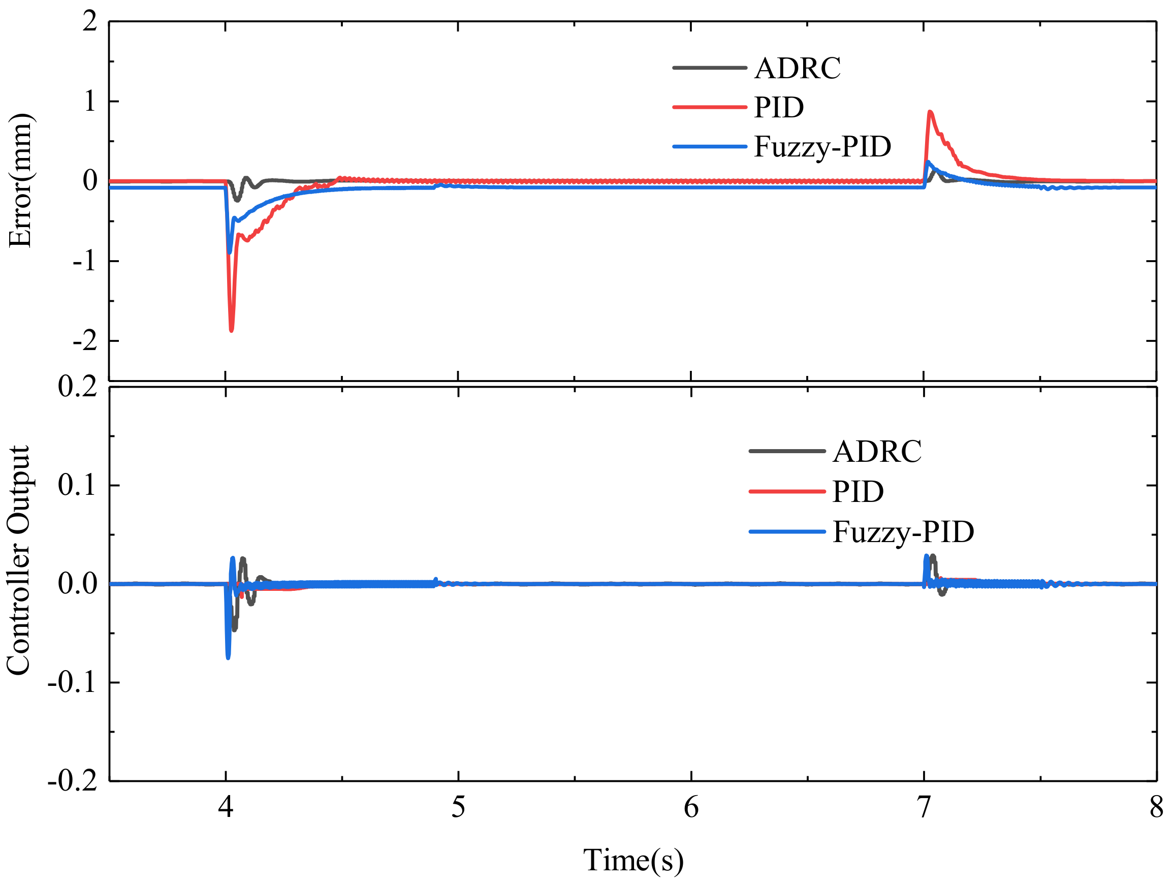
Based on the TD and the ESO, the error of the transition process can be tracked. The feedback control law is constructed by using nonlinear function fal(x,α,δ), so that the steady-state error decreases in the form of power function and the output response speeds up. The controller figures out its output according to the nonlinear combination of the difference between the estimated state variables and the real state variables as Equation (26)
e 1 ( k ) = v 1 ( k ) z 1 ( k ) e 2 ( k ) = v 2 ( k ) z 2 ( k )
u 0 ( k ) = β 1 f a l ( e 1 ( k ) , α 1 , δ ) + β 2 f a l ( e 2 ( k ) , α 2 , δ )
where β1 and β2 are the gain factors. α1 and α2 generally satisfy 0 < α1 < 1 < α2.
The disturbance compensation in Equation (28) depends on the ESO z3 to estimate the total disturbance in real time.
u ( k ) = ( u 0 ( k ) z 3 ( k ) ) / b 0
Actually the output u(k) includes two parts: -z3(k)/b0 is the compensation disturbance component and u0(k) is the integrator series component controlled by the nonlinear feedback.

3. Results

Some preliminary experiments were implemented to verify the necessity of modeling the hose in this system. Figure 6 is the experimental system. Figure 7a shows the position of two cylinders for 5mm command. The power cylinder moves 2.5 mm longer than the target cylinder in experiments. The simulated displacement of the power cylinder is smaller than the tested. It can be interpreted that the bubble in the pressurized oil and the cylinder leakage were not considered in this system. As a result of these two factors, the power cylinder moved longer to make the target cylinder close to the command displacement. Accordingly, the hose model obtained was workable. Figure 7b depicts the position and the pressure of the target cylinder, with a step load and a motionless power cylinder.
Both figures prove that the volume change of the hose cannot be neglected when modeling the system and analyzing its behaviors.
To run a simulation, some parameters for the system and the designed controllers were summarized, as listed in Table 1 and Table 2, respectively:
The step and sinusoidal tracking were set to verify the performance of the TD, as illustrated in Figure 8. It can be seen that the two output trajectories can track the input well.
Comparison of the results with three controllers is demonstrated in Figure 9, with the step response to 50 mm input command with a step load (800 N at 4 s and 400 N at 7 s). It was seen that the displacement response with ADRC at the beginning was faster, achieving steady state in shorter time (stabilizing the output nearly for 0.15 s by ADRC while 1 s by PID or fuzzy PID). As shown in Figure 10, compared with the PID controller and the fuzzy PID controller, the target cylinder with ADRC had smaller error because the ADRC produced a faster and higher-amplitude control signal when the step load interfered with the system output to make the system respond more quickly and reduce the influence of the disturbance on the system. The ADRC used an ESO to obtain the observation of the state variables and disturbances. As shown in Figure 11, the observation results were consistent with the actual items.
Figure 12 illustrates that, when the displacement command stepped from 0 mm to 50 mm, the system using PID control or fuzzy PID control exhibited slower adjustment and less smoothness. The system with ADRC facilitated faster and smoother adjustment to the input. Figure 13 is the phase path for the displacement error at 4 s to 5 s. It implies that the ADRC controller enabled better synthetic control performance than the PID controller or fuzzy PID controller.
Figure 14 depicts the step response under a sinusoidal load (Ft = 100sin(πt + 500 N). The steady-state error of the system using ADRC is smaller than that using the PID, indicating that ADRC has better robustness. The output of the two controllers is illustrated in Figure 15. The output of the ADRC is similar to the PID controller, The ADRC has similar output to the PID controller, but the control performance of the system using the ADRC is better. Thus, it reflects the advantages of ADRC on robustness. Figure 16 shows the estimated speed, displacement and total disturbance of the target cylinder via the ESO. Its observation value is basically qualified and can lay a foundation of high-performance control to analogous uncertain systems.
In order to further study the tracking performance and robustness of the ADRC, simulation for the sinusoidal tracking was carried out. Figure 17 shows the output at a sinusoidal input without load. It reveals that the system using the ADRC tracked the input well, while that using PID had a lag. Figure 18 depicts the sinusoidal response of the system under a constant load. The ADRC facilitated the output tracking and the PID control tended to result in a considerable lag. In Figure 19, the output of the PID controller was smoother, and it had advantages over the ADRC in engineering implementation, so it could reduce the wastage of the motor. Figure 20 demonstrates that the estimated state variables and total interference were also consistent with the actual results. Generally, the system with ADRC had better tracking effects and robustness under constant force disturbance.
Figure 21 depicts the system output at a sinusoidal input under a random load. It reveals that the system using PID and fuzzy PID had a certain lag than that using ADRC. As shown in Figure 22, the system using ADRC also had better tracking effect and robustness under random load interference, compared with that using PID controller or fuzzy PID controller. Figure 22 implies that the ADRC produced high-amplitude output, but there was a certain oscillation in the controller output. Figure 23 shows the estimated states and total disturbance. The analysis above indicates that the ADRC enabled faster response and higher accuracy for the actuation. Additionally, the disturbance and uncertain parameters estimated by the ESO substantially enhanced the system robustness.

4. Conclusions

In this paper, an ADRC strategy is proposed for the double-cylinder hydrostatic actuator to improve the dynamic and steady performance in the presence of uncertain model parameters and external load. The mathematical modeling and simulations were executed to verify the effects of the ADRC on the system. Considering elastic deformation, the hose used in the system was modeled by dint of the centralized parameter method. Under a step and sinusoidal command without load, the system which used ADRC had higher accuracy and better dynamic performance than that which used the conventional PID or fuzzy PID. In terms of anti-interference, the system which used the ADRC was superior to the other two systems. Although for a sinusoidal command, the output of the PID controller was smoother, the disturbance rejection ability of the ADRC was better. In contrast, the ADRC had stronger robustness and superior output, which can provide some guidance for engineering practice.

Author Contributions

B.W. performed the experimental investigation. H.J. built the mathematical model and analyzed the simulation data. B.W. wrote the paper. H.J. and R.C. contributed to the discussion of the results. All authors have read and agreed to the published version of the manuscript.

Funding

This study was financially supported by the Natural Science Foundation of Jiangsu Province (Grant No BK20171412), and partially by the National Natural Science Foundation of China (Grant No 51575257).

Conflicts of Interest

The authors declare no conflict of interest.

References

  1. Chao, Q.; Zhang, J.; Xu, B.; Huang, H.; Pan, M. A Review of High-Speed Electro-Hydrostatic Actuator Pumps in Aerospace Applications: Challenges and Solutions. J. Mech. Des. 2019, 141, 050801-1. [Google Scholar] [CrossRef] [Green Version]
  2. Kim, J.-H.; Hong, Y.-S. Improvement of Backdrivability of a Force-Controlled EHA by Introducing Bypass Flow Control. Int. J. Precis. Eng. Manuf. 2020, 21, 819–830. [Google Scholar] [CrossRef]
  3. Fu, Y.; Han, X.; Sepehri, N.; Zhou, G.; Fu, J.; Yu, L.; Yang, R. Design and performance analysis of position-based impedance control for an electrohydrostatic actuation system. Chin. J. Aeronaut. 2018, 31, 584–596. [Google Scholar] [CrossRef]
  4. Ahn, K.K.; Nam, D.N.C.; Jin, M. Adaptive Backstepping Control of an Electrohydraulic Actuator. IEEE/ASME Trans. Mechatron. 2013, 19, 987–995. [Google Scholar] [CrossRef]
  5. Dong, L.; Yan, H.; Feng, L.; Tan, Q. Modelling and performance analysis of designed energy-efficient eha under gravity loads. Internat. J. Model. Identificat. Control 2018, 30, 253–260. [Google Scholar] [CrossRef]
  6. Minav, T.; Pietola, M.; Filatov, D.M.; Devyatkin, A.V.; Heikkinen, J. Fuzzy control of direct-driven hydraulic drive without conventional oil tank. In Proceedings of the 2017 XX IEEE International Conference on Soft Computing and Measurements (SCM), St. Petersburg, Russia, 24–26 May 2017; Institute of Electrical and Electronics Engineers (IEEE): Piscataway, NJ, USA, 2017; pp. 444–447. [Google Scholar]
  7. Minav, T.; Heikkinen, J.; Schimmel, T.; Pietola, M. Direct Driven Hydraulic Drive: Effect of Oil on Efficiency in Sub-Zero Conditions. Energies 2019, 12, 219. [Google Scholar] [CrossRef] [Green Version]
  8. Hyvärinen, J.; Karlsson, M.; Zhou, L. Study of concept for hydraulic hose dynamics investigations to enable understanding of the hose fluid–structure interaction behavior. Adv. Mech. Eng. 2020, 12, 1–18. [Google Scholar] [CrossRef]
  9. Farong, K.; Zhe, W.; Jiafeng, D.U.; Dong, L.I.; Jianan, X.U.; Linglan, H.E. Study on force tracking control of eha active suspensions. China Mech. Eng. 2017, 28, 2964–2970. [Google Scholar] [CrossRef]
  10. João, F.C.; João, B.P.; Fernando, G.A. Accurate motion control of a pneumatic linear peristaltic actuator. Actuators 2020, 9, 63. [Google Scholar] [CrossRef]
  11. Hao, W.; Kan, J. Application of self-tuning fuzzy proportional-integral-derivative control in hydraulic crane control system. Adv. Mech. Eng. 2016, 8, 1–10. [Google Scholar] [CrossRef] [Green Version]
  12. Truong, D.Q.; Ahn, K.K. Force control for hydraulic load simulator using self-tuning grey predictor—Fuzzy PID. Mechatronics 2009, 19, 233–246. [Google Scholar] [CrossRef]
  13. Ahn, K.K.; Truong, D.Q.; Thanh, T.Q.; Lee, B.R. Online self-tuning fuzzy proportional—Integral—Derivative control for hydraulic load simulator. Proc. Inst. Mech. Eng. Part I J. Syst. 2008, 222, 81–95. [Google Scholar] [CrossRef]
  14. Ye, Y.; Yin, C.-B.; Gong, Y.; Zhou, J.-J. Position control of nonlinear hydraulic system using an improved PSO based PID controller. Mech. Syst. Signal Process. 2017, 83, 241–259. [Google Scholar] [CrossRef]
  15. Esfandiari, M.; Sepehri, N.; Esfandiari, M. Controller Design and Stability Analysis of Output Pressure Regulation in Electrohydrostatic Actuators. J. Dyn. Syst. Meas. Control. 2018, 141, 041008. [Google Scholar] [CrossRef]
  16. Erik, E.; Georg, B.; Nathan, M. Analysis of the influence of suspension actuator limitations on ride comfort in passenger cars using model predictive control. Actuators 2020, 9, 77. [Google Scholar] [CrossRef]
  17. Yang, R.; Fu, Y.; Zhang, L.; Qi, H.; Han, X.; Fu, J. A Novel Sliding Mode Control Framework for Electrohydrostatic Position Actuation System. Math. Probl. Eng. 2018, 2018, 1–22. [Google Scholar] [CrossRef]
  18. Bone, G.M.; Xue, M.; Flett, J. Position control of hybrid pneumatic–electric actuators using discrete-valued model-predictive control. Mechatronics 2015, 25, 1–10. [Google Scholar] [CrossRef]
  19. Yang, G.; Yao, J. Output feedback control of electro-hydraulic servo actuators with matched and mismatched disturbances rejection. J. Frankl. Inst. 2019, 356, 9152–9179. [Google Scholar] [CrossRef]
  20. Castañeda, L.; Luviano-Juárez, A.; Ochoa-Ortega, G.; Chairez, I. Tracking control of uncertain time delay systems: An ADRC approach. Control. Eng. Pr. 2018, 78, 97–104. [Google Scholar] [CrossRef]
  21. Wu, Y.; Zheng, Q. ADRC or adaptive controller—A simulation study on artificial blood pump. Comput. Biol. Med. 2015, 66, 135–143. [Google Scholar] [CrossRef] [PubMed]
  22. Xue, W.; Bai, W.; Yang, S.; Song, K.; Huang, Y.; Xie, H. ADRC with Adaptive Extended State Observer and its Application to Air–Fuel Ratio Control in Gasoline Engines. IEEE Trans. Ind. Electron. 2015, 62, 5847–5857. [Google Scholar] [CrossRef]
  23. Zhu, E.; Pang, J.; Sun, N.; Gao, H.; Sun, Q.; Chen, Z. Airship horizontal trajectory tracking control based on Active Disturbance Rejection Control (ADRC). Nonlinear Dyn. 2013, 75, 725–734. [Google Scholar] [CrossRef]
  24. Wu, Z.-H.; Guo, B.-Z. Approximate decoupling and output tracking for MIMO nonlinear systems with mismatched uncertainties via ADRC approach. J. Frankl. Inst. 2018, 355, 3873–3894. [Google Scholar] [CrossRef]
  25. Aboudrar, I.; el Hani, S.; Heyine, M.S.; Naseri, N. Dynamic Modeling and Robust Control by ADRC of Grid-Connected Hybrid PV-Wind Energy Conversion System. Math. Probl. Eng. 2019, 2019, 1–19. [Google Scholar] [CrossRef] [Green Version]
  26. Liu, C.; Luo, G.; Chen, Z.; Tu, W.; Qiu, C. A linear ADRC-based robust high-dynamic double-loop servo system for aircraft electro-mechanical actuators. Chin. J. Aeronaut. 2019, 32, 2174–2187. [Google Scholar] [CrossRef]
  27. Tian, Y.; Liu, B.; Gao, H.W.; Li, W.Q. Modeling and Simulation of Electro-Hydraulic Proportional Position Control System with the Flexible Hose. Adv. Mater. Res. 2012, 468, 2094–2099. [Google Scholar] [CrossRef]
Figure 1. Schematic diagram of the whole system. 1. Force transducer; 2. Load mass; 3. LVDT; 4. Target cylinder; 5. Hose; 6. Accumulator; 7. On/off valve; 8. Power cylinder; 9. Ball screw; 10. Stepping motor; 11. Loading system.
Actuators 09 00112 g001
Figure 2. Hose model.
Actuators 09 00112 g002
Figure 3. Viscoelastic model for hoses.
Actuators 09 00112 g003
Figure 4. Displacement of the target cylinder and pressure in the rodless chamber.
Actuators 09 00112 g004
Figure 5. Schematic diagram based on active disturbance rejection control (ADRC).
Actuators 09 00112 g005
Figure 6. Experimental system.1. Stepping motor; 2. Ball screw; 3. Power cylinder; 4. Target cylinder; 5. Force transducer; 6. LVDT; 7. Pressure transducer; 8. Accumulator (oil compensation tank); 9. Hose.
Actuators 09 00112 g006
Figure 7. (a). Displacement of two cylinders. (b). Displacement of the target cylinder and pressure in the rodless chamber.
Actuators 09 00112 g007
Figure 8. Step and sinusoidal tracking displacement.
Actuators 09 00112 g008
Figure 9. Response to step load.
Actuators 09 00112 g009
Figure 10. Error and controller output.
Actuators 09 00112 g010
Figure 11. Observations made by extended state observer.
Actuators 09 00112 g011
Figure 12. Phase path for the displacement error from 0mm to 50 mm.
Actuators 09 00112 g012
Figure 13. Phase path for the displacement error from 4 s to 5 s.
Actuators 09 00112 g013
Figure 14. Response to a sinusoidal load.
Actuators 09 00112 g014
Figure 15. Error and controller output.
Actuators 09 00112 g015
Figure 16. Observations by the ESO.
Actuators 09 00112 g016
Figure 17. Sinusoidal response.
Actuators 09 00112 g017
Figure 18. Responses to constant load.
Actuators 09 00112 g018
Figure 19. Error and controller output.
Actuators 09 00112 g019
Figure 20. Observations by ESO to constant load.
Actuators 09 00112 g020
Figure 21. Responses to random load.
Actuators 09 00112 g021
Figure 22. Error and controller output.
Actuators 09 00112 g022
Figure 23. Observations made by extended state observer.
Actuators 09 00112 g023
Table 1. The servo system’s parameters.
ParameterValueParameterValueParameterValue
m50 kgr0.003 mc1140
AP13.77 × 10−4 m2l10 mγ10.5
AP24.91 × 10−4 m2k116 × 105c2120
AA13.14 × 10−4 m2k125000γ20.1
AA22.01 × 10−4k21 × 106cj[−1.0 −0.5 0 0.5 1]
fs50 Nμvisc200 N·s/mbj5
Table 2. The controller’s parameters.
ParameterValueParameterValueParameterValue
P7β02100α20.4
I0.01β0330b00.02
h0.002β150b5
h00.002β20.1r0.005
β0150α10.5δ0.001
Publisher’s Note: MDPI stays neutral with regard to jurisdictional claims in published maps and institutional affiliations.

