Article

Comparing the Accuracy of sUAS Navigation, Image Co-Registration and CNN-Based Damage Detection between Traditional and Repeat Station Imaging

1
Department of Geography, San Diego State University, San Diego, CA 92182-4493, USA
2
Bren School of Environmental Science & Management, University of California at Santa Barbara, Santa Barbara, CA 93106-5131, USA
*
Author to whom correspondence should be addressed.
Geosciences 2022, 12(11), 401; https://doi.org/10.3390/geosciences12110401
Submission received: 4 August 2022 / Revised: 2 October 2022 / Accepted: 24 October 2022 / Published: 28 October 2022
(This article belongs to the Special Issue Mapping and Assessing Natural Disasters Using GIScience Technologies)

Abstract

:
The application of ultra-high spatial resolution imagery from small unpiloted aerial systems (sUAS) can provide valuable information about the status of built infrastructure following natural disasters. This study employs three methods for improving the value of sUAS imagery: (1) repeating the positioning of image stations over time using a bi-temporal imaging approach called repeat station imaging (RSI) (compared here against traditional (non-RSI) imaging), (2) co-registration of bi-temporal image pairs, and (3) damage detection using Mask R-CNN, a convolutional neural network (CNN) algorithm applied to co-registered image pairs. Infrastructure features included roads, buildings, and bridges, with simulated cracks representing damage. The accuracies of platform navigation and camera station positioning, image co-registration, and resultant Mask R-CNN damage detection were assessed for image pairs, derived with RSI and non-RSI acquisition. In all cases, the RSI approach yielded the highest accuracies, with repeated sUAS navigation accuracy within 0.16 m mean absolute error (MAE) horizontally and vertically, image co-registration accuracy of 2.2 pixels MAE, and damage detection accuracy of 83.7% mean intersection over union.

1. Introduction

Aerial imaging and digital image processing are critical disaster response tools used throughout disaster management for saving lives and identifying damaged roads, bridges and buildings [1]. The application of airborne remote sensing for post-hazard damage assessment can provide valuable and timely information with high spatial resolution for areas subject to disasters, where direct observation may be hazardous or untimely. Still, the use of aerial imagery for disaster response can be challenging. Challenges include the correct choice of imagery (i.e., spatial and spectral resolutions), collection methods (i.e., piloted and unpiloted aircraft, satellite) and the timeliness and accuracy of information delivery [1,2]. This study examines the utility of small unpiloted aerial systems (sUAS), repeat station imaging (RSI), and convolutional neural networks (CNN) as solutions to these challenges.
This study addresses the challenge of information accuracy when sUAS are used to collect multi-temporal imagery for post-hazard damage detection, with the following four objectives: (1) evaluate the capacity of low-altitude sUAS systems to repeat the positioning of image stations with high-precision and accuracy; (2) evaluate the impact of RSI versus non-RSI image acquisition techniques on co-registration of sUAS images acquired with nadir and oblique view perspectives; (3) develop a software application for automatic image co-registration and CNN-based detection of damage to critical infrastructure; and (4) compare the damage detection accuracy of a CNN employed with bi-temporal image pairs, acquired with both RSI and non-RSI approaches.

2. Background

Many disaster management organizations follow a structured framework called the disaster management cycle (DMC) when preparing for and responding to hazardous events [1,2,3,4]. This cycle consists of six phases, as illustrated in Figure 1. Pre-disaster and intra-disaster phases are reconstruction, mitigation and preparedness, which range from months to years in duration [1,3,4]. Post-disaster phases are rescue, relief and recovery, which range from minutes to days in duration. Detailed and timely information about the status of critical infrastructure is of utmost importance during these stages [1,4].
Based on feedback from emergency managers, areas representing critical infrastructure (i.e., bridges, roads, dams, hospital buildings, prison complexes) comprise the features of interest. The requirements of a remote sensing system for emergency management are heavily dependent upon the DMC phase. Specific needs stem from the type of disaster event and the expected manifestations and severity of damage [1,3,5,6]. Primary damage resulting from earthquakes, such as cracking, subsidence and collapsing of buildings, is better detected with high spatial resolution imagery (ground sample distance (GSD) < 5 m) and the inclusion of building height data [1,7,8]. For the detection of damage to critical infrastructure, where fine-scale damage detection is necessary, spatial resolutions of <1 m may be required [6]. This research focuses on cracking, an important sign of damage symptomatic of earthquakes.
Unpiloted aerial systems (UAS) are currently being studied and used operationally for image acquisitions to address problems related to the timeliness of damage detection [9]. Small UAS (sUAS), weighing less than 25 kg, are capable of being deployed at lower-cost and with less technical training than manned aircraft or their larger unmanned counterparts; they are capable of multi-spectral imaging, and their operation at low altitudes makes them ideal for capturing images with hyper-spatial resolutions [10,11]. UAS remote sensing for both rapid (within 24 h) and near real-time (imagery is processed and delivered as a disaster is occurring) hazard response improves upon piloted aerial and satellite platform timeliness delays of up to 72 h. Though sUAS generally can only lift light-weight imaging sensors, the trend of increasing sensor spatial resolutions while simultaneously steadily decreasing their physical size and weight means that hyper-spatial ground resolutions (GSD = c. 1 mm) can be achieved using consumer-off-the-shelf digital cameras [12,13,14].
Acquisition of sUAS imagery is typically achieved using parallel overlapping flight lines, with a frame-based sensor designed to capture images based upon either time or distance intervals [15] that provide sufficient forward-lap and side-lap to ensure features are viewed from multiple perspectives (i.e., parallax). While differential parallax between multiple images of the same features permits aerial triangulation, it makes co-registration between repetitive imaging of the same area or features challenging [16,17]. Parallax introduces variable relief displacement between multi-temporal images [18]. The distortions in vertical features and co-registration errors between time-sequential images, resulting from varied view geometries, reduces the accuracy of image registration and therefore changes detection results [16,17,19].
Repeat station imaging (RSI) is an alternative method for acquiring imagery for use in change detection. RSI uses pre-planned flight paths and waypoints (i.e., x–y–z positions in the sky) to navigate the platform to the same positions over time using global navigation satellite systems (GNSS), and the imaging sensor is triggered at these pre-specified camera stations (with unique viewing perspectives at each individual waypoint) [4,16]. This acquisition method has been demonstrated to improve the co-registration accuracy of time-sequential images, a critical factor in achieving reliable image-based change detection [16,17,20]. Provided the same sensor is used across acquisitions, the result is “multitemporal imagery with matched view geometry” [4]. This method of image acquisition has been shown to result in horizontal spatial co-registration errors between multitemporal image sets of between one to two pixels, even at high spatial resolutions [16]. Evidence from the RSI literature suggests that damage detection can be performed more accurately using RSI than with traditional acquisition methods, even where damage occurs in three-dimensions [21].
Research on image change detection consistently shows that image co-registration accuracy directly impacts the accuracy of change detection results [17,19]. Horizontal and vertical differences between image pairs have been the focus of the existing literature on RSI [16]. RSI yields higher image co-registration accuracy than conventional implicit image registration approaches when employed with image differencing, and should be useful in CNN-based change detection [19,22,23].
Traditionally, feature detection, localization, and change detection have been performed in the remote sensing context using methods such as image differencing, object-based image analysis, supervised and unsupervised classifications with support vector machines, and earlier versions of artificial neural network algorithms [24]. More recently, researchers using remote sensing for environmental sciences and engineering problems have developed CNN models as means of achieving higher classification accuracies [24,25].
Convolutional neural networks (CNN) are an emergent technology with potential for advancements in image segmentation, pattern recognition, and change detection [26,27]. CNNs and related deep learning algorithms are shown to provide improved accuracies over other image segmentation and classification techniques, such as object-based change detection and various supervised and unsupervised classifiers [27]. CNNs utilize a fundamental digital image processing technique called “convolution”. Images are convolved into their most basic components, and subsequently reconstructed with a set of automatically generated and estimated parameters [28]. Parameters that lead to closer matching reconstructions receive preferential weight, and are transferred to the next convolution as starting parameters. Each subsequent convolution attempts to perform less smoothing and thus learn parameters for reconstructing higher-level, finer-scale features. Most of the CNN literature focuses on single-date image classification, with only a few recent examples of their application to change detection. CNN-based change detection can be performed with post-classification analysis across multi-temporal datasets and, as we demonstrate, direct change detection with co-registered and stacked bi-temporal image pairs [29,30].
In the domain of remote sensing, CNNs have been applied to spaceborne and airborne imagery, with pre-trained and fine-tuned models yielding accurate results. Most published work in this domain has focused on the scene labeling problem, also referred to in the literature as semantic segmentation and labeling, which refers to accurate image classification by pixel or object [26,29,30]. Mimicking the geographic-based image change analysis (GEOBICA) approach with CNN learning, where co-registered bi-temporal image pairs are used to find change objects, promises to result in improvements to change (e.g., damage) detection accuracy over other post-classification change detection approaches [31]. This study employs a novel use of the Mask R-CNN model to bi-temporal imagery for the purpose of change detection. The Mask R-CNN algorithm uses bounding box regression for identification of objects (regions of interest) and semantic segmentation for classification of object pixels [32].

3. Methods

3.1. Study Area

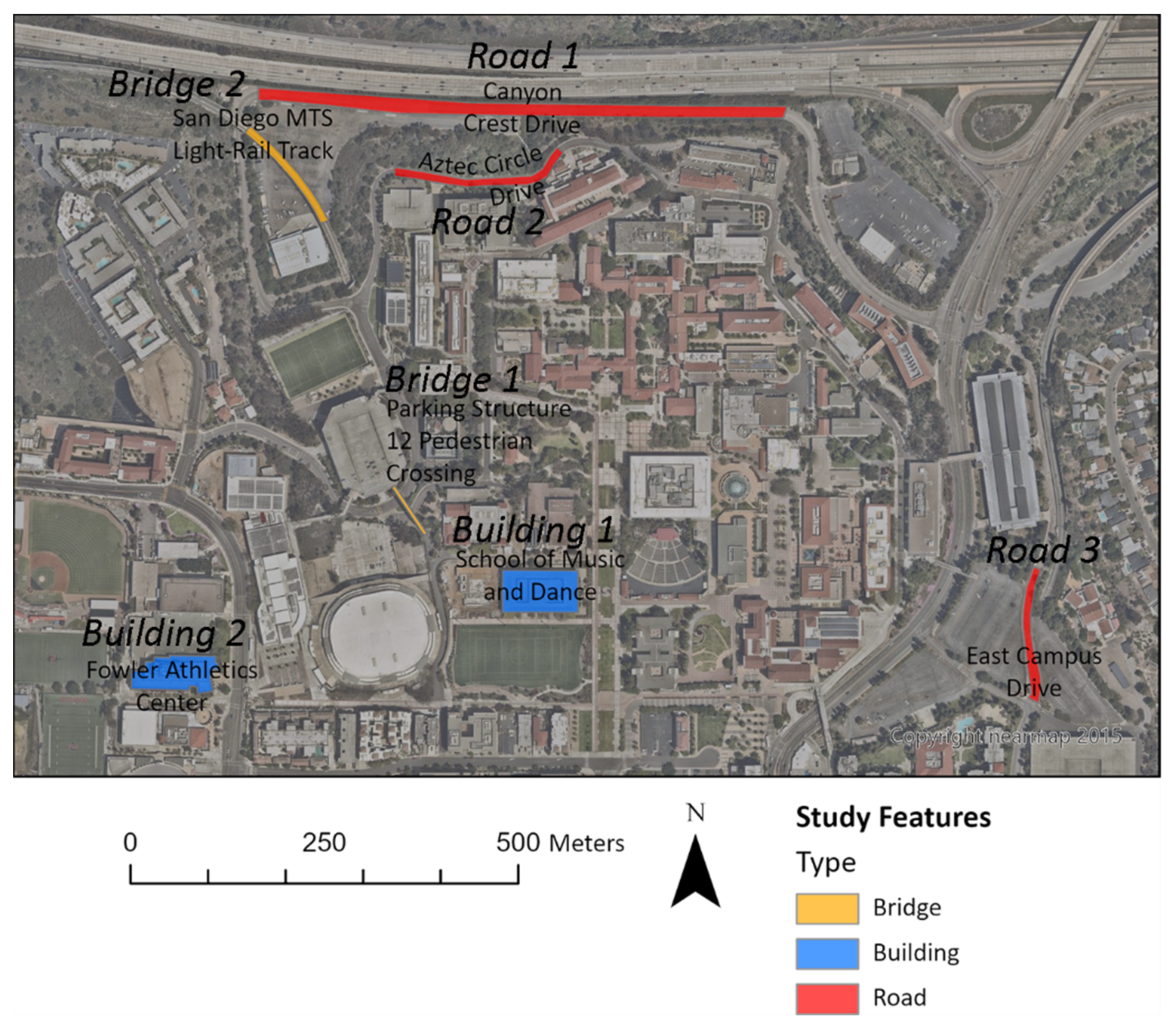
The primary study area is the San Diego State University (SDSU) campus, with specific study sites selected to contain multiple features of interest representative of critical infrastructure. To meet the research objectives, features of interest for the SDSU study sites were selected to represent critical infrastructure that has been damaged. These features include roads, buildings, and bridges. Table 1 provides details on-site selection criteria. Given the need for substantial quantities of data to be collected and relationships established with administrative and law-enforcement officials, all sites are located on the SDSU campus. The map in Figure 2 shows the locations of the features of interest.
Simulated post-hazard cracks were placed on concrete (buildings, bridges) and asphalt (roads). The structures, imaging view perspectives, simulated cracks and the surroundings (i.e., sidewalks, cars, vegetation) were chosen so images would be representative of actual inspections.

3.2. General Approach

Two sUAS with sensors of different sizes and focal length settings were used to acquire images of these features, using both RSI and non-RSI acquisition methods. The types of damage of interest are cracks, and both subsidence and partial collapse of structures were simulated for the collected imagery. Subsequent-time (i.e., repeat-pass) images with the simulated damage were co-registered to baseline images. Some co-registered image pairs were used to train the CNN, and others used to detect damage. The accuracies of platform navigation, image co-registration, and resultant CNN damage detection were assessed for the RSI and non-RSI acquisition methods.
The collection and processing of images requires specialized hardware components. Accurate repeated imaging of features requires a real-time-kinematic (RTK) GNSS with a ground-based unit placed on a surveyed control marker and a mobile RTK unit on the sUAS. Additionally, gimbal mounts with the capability of pointing cameras at specified angles are required for repeating the capture of oblique view geometries. The equipment meeting the above criteria and used in this research was an Emlid Reach RS2 RTK base unit and the DJI Matrice 300 sUAS with a Zenmuse H20 camera/gimbal combination. A DJI Mavic 1 sUAS without RTK capability was also used in additional assessments of non-RSI acquisitions.
Image processing requires substantial computing resources; high-end graphics cards and memory availability are critical. Many image-processing applications facilitate co-registering and transforming images, including options from Hexagon Geospatial, Esri, and Adobe. However, no software resources are available for performing the needed automatic co-registrations and coordinate transformations in bulk, while simultaneously providing accurately georeferenced image outputs for use with neural network classification. We developed the application “Image Pre-Processing” (IMPP) for this research to provide bulk image transformations, automatic co-registration of image pairs based on geographic proximity, and the selection of CNN models for damage detection.
Data pre-processing was performed on all collected images with two primary goals: (1) simulate damage and (2) co-register time-sequential image pairs. Damage simulation was performed using Adobe Photoshop for two-dimensional representations of damage. Geometric and radiometric image transformations was performed using IMPP.

3.2.1. Data Acquisition

The primary data acquired were repetitive sUAS images of the study area features and image-related metadata. With surface cracks as the primary damage of interest, a ground sample distance (GSD) of 0.5 cm was chosen for all images. The flight plans for nadir and oblique imaging with the Matrice 300 and Mavic 1 sUAS used camera stations, designed to achieve the 0.5 cm GSD by setting the appropriate altitudes and distances from the features to be imaged. Following the terrain with the sUAS was not a consistently available option due to coarse resolution elevation models in the flight-planning software. Thus, where terrain varies in elevation the GSD deviates by +/- 0.2 cm. Flight plans for oblique (i.e., off-nadir) imaging were based on a set gimbal angle of 45-degrees.
Mavic 1 flight planning was performed with Litchi application software (VC Technology, 2020, Manassas Park, Virginia, USA) and the Matrice 300 with the UgCS application software (SPH Engineering, version 3.82, Riga, Latvia). The specific sensor information for both platforms is shown in Table 2. The Zenmuse H20 incorporates a zoom lens; the focal length was fixed to the same parameter for all flights.
The RSI acquisition method requires repeating the view geometries by triggering the camera at the same station locations and view angles, ideally with the same sensor [19]. This is achieved with the Matrice 300 using the onboard RTK capabilities and an Emlid Reach RS2 base station, mounted on a fixed location for all flights. The baseline flights and all RSI-based flights were repeated with this setup.
The non-RSI method is the default behavior of the Mavic 1 and Matrice 300. The Mavic 1 does not have RTK capability, and for the Matrice 300 the RTK functionality was disabled. This change limits the navigational accuracy and repeatability of waypoints for the platforms, and their GNSS positions are more susceptible to changes in satellites’ ephemeris. The baseline images for each feature are based on and identical to the RSI method, and repeated flights use the non-RSI parameters.
Given that the Matrice 300 is flown with the same sensor for both the RSI and non-RSI flights, the image co-registration and Mask R-CNN accuracy results for that platform should vary only by the collection method. With the Mavic 1, which is not capable of RTK-based precise navigation, the image co-registration and Mask R-CNN results are intended to enable a comparison between the whole system (i.e., platform, sensor, navigation capabilities and collection method) and one aspect which does support precise navigation (Matrice 300).
For each feature in the study area, the number and locations of waypoints were based on the sizes of the features and the 0.5 cm GSD requirement. With the Matrice 300, a baseline flight was conducted for each feature, and subsequently repeated nine times with the RSI method and two times with the non-RSI method. With the Mavic 1, a baseline imaging mission was conducted for each study feature and repeated nine times with the non-RSI method. Each repetition was flown sequentially, with up to 3 h passing between the baseline and final repeat being flown. The number of baseline waypoints and images collected for each feature by platform is shown in Table 3.
The sample sizes displayed in Table 3 represent two sUAS platforms with differing capabilities. For platform navigation and image co-registration assessments, the Mavic 1 contained 112 waypoints, repeated 887 times, and the Matrice 300 contained 61 waypoints, repeated 706 times both with and without RTK enabled.

3.2.2. Software Development

We developed IMPP to accurately and automatically co-register and georeference sUAS image pairs in bulk and perform CNN-based damage detection. IMPP is a Python 3 application with a graphical user interface. It utilizes several open source image processing and geographic information systems modules: OpenCV, GDAL, NumPy and SciPy.
The graphic interface of IMPP divides the application into two tabs. The Georeferencing tab is used to automatically co-register and georeference image pairs in bulk. The AI Inference tab allows for the selection of a trained neural network model and the automatic classification of damage in images or image pairs. The design and training of neural network models is performed by modifying python scripts which are included in IMPP but are not part of the graphic interface.
When using the georeferencing functionality, baseline imagery and repeated imagery’s geographic coordinates and sensor information were loaded. They were subsequently used to automatically find bi-temporal image pairs and their georeferenced spatial extents, based on the user-specified EPSG geographic coordinate projection. This information was saved in a project GeoPackage as point layers.
Oriented FAST and Rotated BRIEF (ORB) is an open source feature detector in OpenCV that is used to detect and assign identifiers to unique features in each image within an image pair. With the features identified, IMPP then searches for matched features by counting the number of positions in the feature identifiers that differ.
Matched features from the two images were passed through a planar homography algorithm that finds the 3 × 3 transformation matrix, with 8 degrees of freedom, between the images. This transformation matrix was used with a perspective transformation to align the time-n image to the baseline image. At this point, image pairs were exported to a folder as georeferenced GeoTiffs.
In addition to the co-registered image outputs, IMPP was designed to output useful processing logs. Co-registration accuracy is automatically assessed by performing the ORB feature detection and matching using new points on the already co-registered image pairs, and both root-mean-square and mean absolute error are output into comma-separated files. Additionally, the percent of time-n images’ pixel overlaps with the baseline images was calculated and saved to the logs.

3.2.3. Damage Simulation

Due to limitations in data availability for actual post-hazard damage features, manifestations of damage were artificially added or removed from imagery using photography editig software. This generated bi-temporal image pairs containing no damage, and then damage for portions of structures. The structural features were chosen to resemble critical infrastructure. The imaged structural features either already contained damage (cracks), or were undamaged and a method for simulating an undamaged and a damaged state was employed. Fine-scale cracks were chosen as the sole damage type as they (1) are expected to present a challenge in automated bi-temporal change detection where image mis-registration occurs, and (2) are simpler to simulate than other damage types.
When a feature in the baseline imagery already contained cracks, (i.e., a road, bridge, or building that has surface cracks), the Adobe Photoshop healing tool was used to remove some but not all cracks. When a feature in the subsequent (non-baseline) imagery did not contain cracks, Photoshop’s clone, rotation, and skew tools were used to transfer cracks from other damaged features with similar background surface types to the undamaged features.
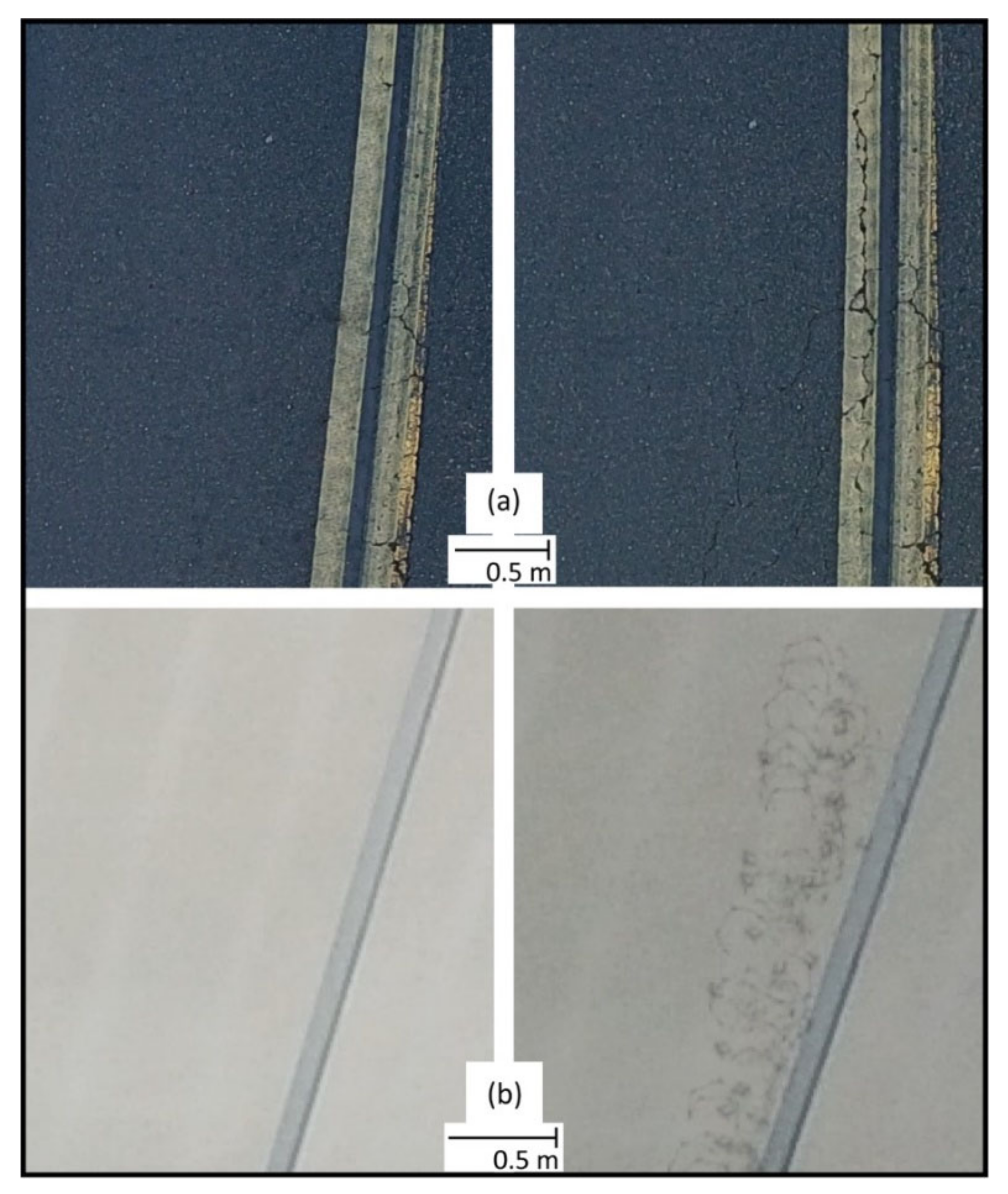
This approach to damage simulation yielded bi-temporal images containing radiometrically, spatially and contextually realistic changes, where the pre-disaster imagery portrays features in a pre-disaster state and post-disaster imagery with new damage. Figure 3 shows an example of an original baseline image containing existing cracks, the result from removing the damage and a subsequent-time image where cracks were artificially added.

3.2.4. Image Pre-Processing

The image pre-processing steps accomplished three goals following damage simulation:
(1) co-register and georeferenced bi-temporal image pairs (described above), (2) prepare imagery for use in neural network training and (3) prepare imagery for use in neural network-based damage detection. For each of the study area’s features, two projects were created in IMPP to co-register and georeference the Mavic 1 and Matrice 300 images, following procedures detailed in the IMPP Software Development section above.
Georeferenced image pairs were then loaded into a GIS application, QGIS, and image pixels were labeled using a binary mask of 0 (no damage) or 1 (damage). All images for all features and both drone platforms were then split into two datasets: a training dataset and a classification dataset. The training dataset contained 70% of the images and labels, and the classification dataset contained the other 30% of images and labels. Examples of a baseline image, layer-stack, and damage labels for a pedestrian bridge, taken with the Matrice 300 are shown in Figure 4.

3.2.5. Neural Network Training and Classification

The CNN model used for training is based on Mask R-CNN, which is suitable for semantic segmentation and object detection [32]. Pretraining of the model was previously performed by its developers on a large image dataset of more than 1.5 million images with 100 classes [32]. The process of re-training a model on new data and new classes is called fine-tuning and can be performed with hundreds rather than millions of images [26]. The training and fine-tuning process requires that images be loaded as smaller 1024 × 1024 pixel image regions due to computer memory limitations. The Mask R-CNN model training performs best with a large batch size (16 images per batch). A single image from the Matrice 300 yields 20 images for training, and a single Mavic 1 image can yield six images.
Images were provided to the model as three-band bi-temporal layer stacks with the baseline grayscale image in band 1, the grayscale time-n image in band 2, and a simple image-difference product in band 3. As the images were split into smaller regions for training, the split regions underwent randomized flipping and rotation to increase the overall number of images available for training. Training was performed for 300 epochs.
Three versions of the model were trained and evaluated. The first used the Mavic 1 non-RSI image pairs (4195 images for training, 1798 for evaluation), the second utilized the Matrice 300 non-RSI image pairs (10,738 images for training, 4602 for evaluation), and the third deployed the Matrice 300 RSI image pairs (10,738 images for training, 4602 for evaluation).
The classification products generated from the evaluation images are binary mask rasters in GeoTiff format showing new post-disaster damage and no damage.

4. Analytical Procedures

The analysis focuses on assessing the navigational accuracy and repeat position matching precision of two sUAS for conducting RSI image acquisitions, the effects of RSI and non-RSI acquisition methods on co-registration accuracy at low altitudes (<400 ft or 122 m), and the accuracy of a CNN trained on RSI and non-RSI bitemporal change (i.e., simulated damage) objects.

4.1. RSI and Non-RSI Navigational Accuracy

The RSI and non-RSI navigational accuracies of the platforms were assessed with two metrics. The first is a measurement of distance between planned and actual camera stations, and where the GNSS RTK onboard the platforms indicate the images were actually acquired. Mean absolute error (MAE) and root-mean-square error (RMSE) metrics were generated from the offset values for all flights, per platform. This approach provides navigational and repeatability assessments based on the recorded GNSS RTK positions. Another metric for assessing the repeatability of image stations is the percent of overlap between baseline and repeated images. This metric uses a summation of the percent of non-overlapping pixels for each image pair and divides the percent-sum by the number of images, providing a mean percent error (MPE) measurement.

4.2. Image Co-Registration Accuracy

The co-registration accuracy of images was calculated for RSI and non-RSI pairs after co-registration was performed using IMPP. Automatically generated and matched points within previously co-registered image pairs were used to determine the distances between matched pixels, providing the co-registration error. The automatically generated points were selected from a subset of those used in the co-registration process and are independent of that process (i.e., they were not used to perform co-registration). RMSE and MAE metrics of accuracy were then used to assess the co-registration accuracy.

4.3. Neural Network Classification Accuracy

CNN classification accuracy was quantified based on known damage features on image pairs that were not used for training the model. As with the pairs used in training, these images have ground reference labels, where pixels representing damage have a class value pre-assigned and non-damaged areas have a background class assigned. Intersection over union (IoU), a metric for calculating the percent of an object that falls inside and outside the area predicted by the CNN, is used to score individual detections of damage. The mean IoU was assessed for the outputs from both RSI- and non-RSI-based CNN models.

5. Results

The results of the navigational and co-registration accuracy assessments clearly demonstrate that RSI image pairs yielded (1) greater repeatability of camera station waypoints, (2) greater overlap of image pairs, and (3) higher image co-registration accuracy. The Mask R-CNN neural network classifier yielded the highest accuracies when applied to the bi-temporal images generated with the RSI acquisition and co-registration approach.

5.1. Navigation and Image Co-Registration Accuracy

The navigational accuracies of the Mavic 1 and Matrice 300 sUAS are dependent on the ability of their GNSS to accurately determine their geographic positions. The Mavic 1 does not utilize RTK for accurate positioning, while the Matrice 300 can be operated with or without RTK positioning.
Table 4 shows the navigation, overlap, and co-registration results, separated by whether images were of nadir or oblique angles and by sUAS platform with RSI/non-RSI approaches. The results are given in terms of both mean absolute error (MAE) and root-mean-square-error (RMSE), with emphasis on MAE due to its lower sensitivity to outliers; RMSE follows the MAE trends in this study. The analysis shows that the navigational accuracy of the Mavic 1 was highly variable, from <20 cm to >9 m. The Matrice 300 with RTK disabled had a navigational accuracy ranging from 13 cm to 30 cm, and with RTK enabled the range was 14 cm to 18 cm.
The image-pair-overlap assessment also shows that RSI yielded greater overlap, which is dependent on platform navigation and sensor pointing accuracy. Image overlap error was consistently lower for the Matrice 300 with RTK enabled (8.6–10.1%) versus disabled (12.5–18.0%), and in most circumstances was much lower than the Mavic 1 (7.6–27.8%).
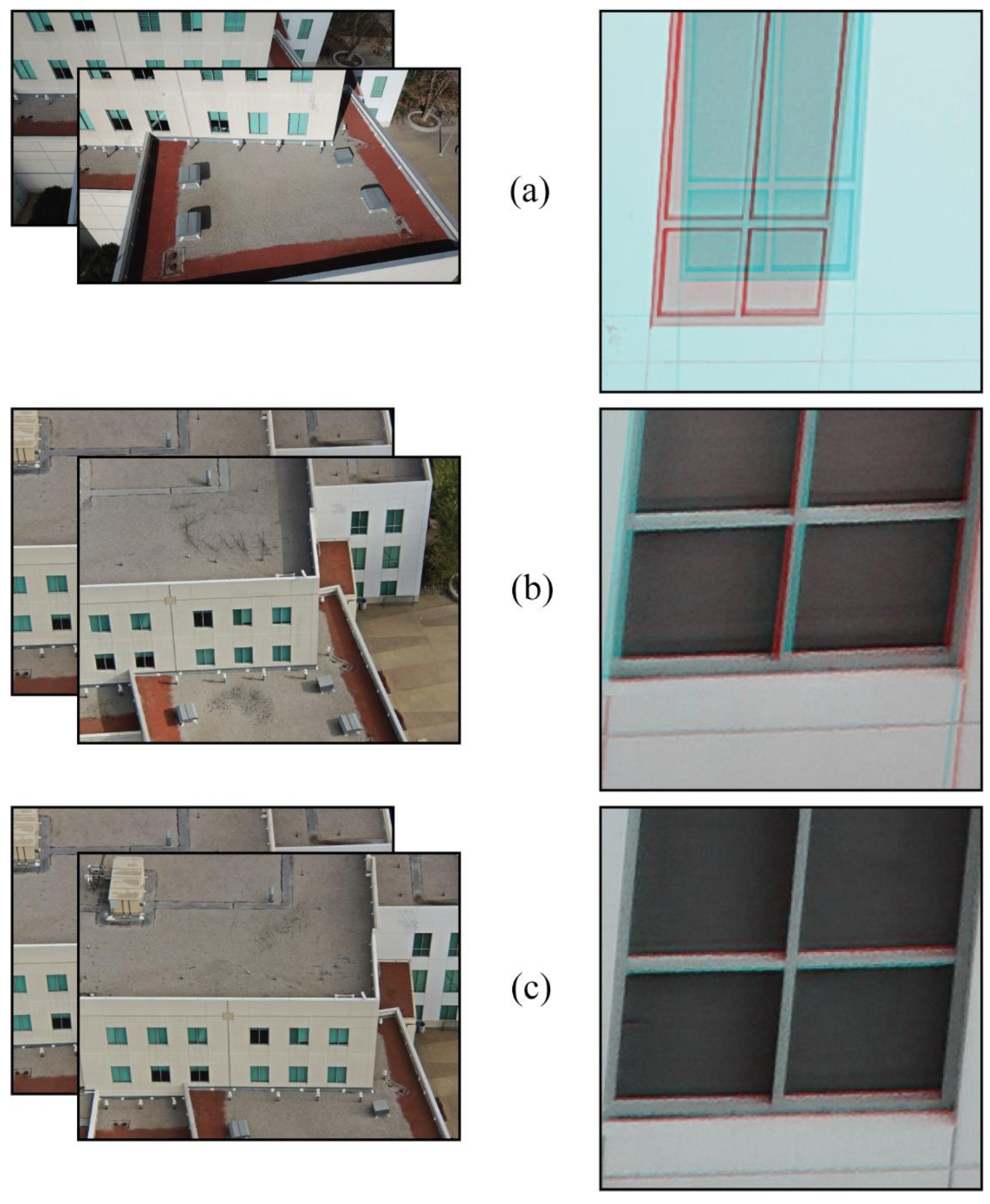
Image co-registration results show a similar pattern, with the RSI method yielding image pairs with the least amount of error. Images from the Matrice 300 with RTK enabled have an MAE of 2.1 pixels (nadir images) to 2.3 pixels (oblique images). With RTK disabled, the M300 images have MAE of 3.8 (nadir) and 5.0 (oblique) pixels. Images from the Mavic 1 yielded the highest MAEs (nadir: 11.0 pixels, oblique: 139.2 pixels). Figure 5 shows image co-registration examples from the Mavic 1 non-RSI and Matrice 300 non-RSI and RSI collections.

5.2. Neural Network Classification Results

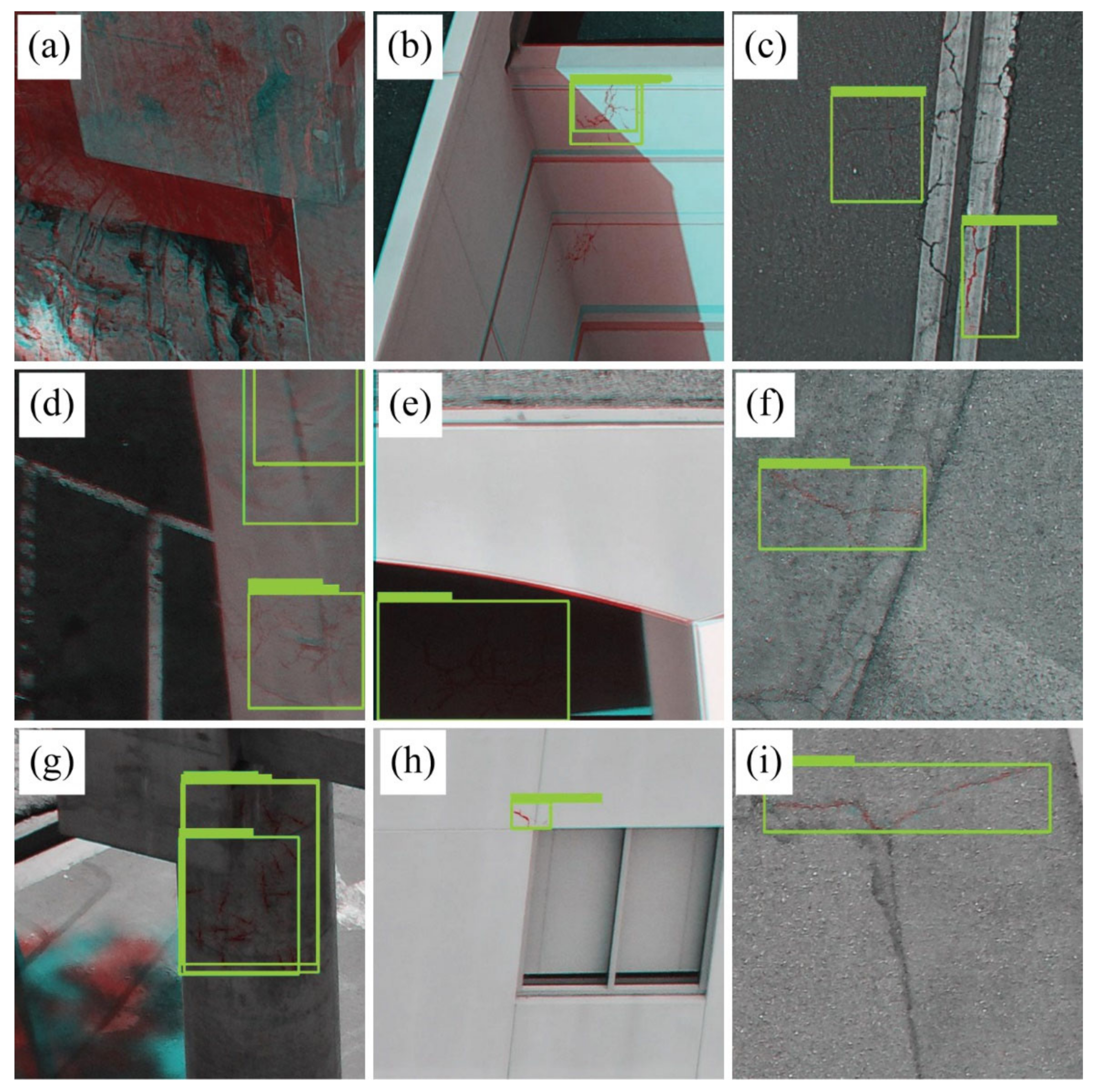
Results from the Mask R-CNN neural network classification show clear variations between acquisition methods (RSI vs. non-RSI), view perspectives (nadir vs. oblique) and feature types (roads, buildings, bridges). Differences in accuracy are also observed by platform type in the case of non-RSI acquisitions. Figure 6 shows examples of damage detection from each of the platforms and collection methods.
Table 5 contains the neural network classification accuracy results presented as mIoU (%). The CNN classifier, trained and tested on RSI-acquired imagery, outperformed the non-RSI classifiers by an average of 20.5% mIoU and with an overall accuracy of 83.7% mIoU.
A plot showing the relationship between the nadir and oblique RSI and non-RSI Mask R-CNN mIoU results, against their associated image co-registration MAE values, is shown in Figure 7. From this, an inverse linear trend is evident, such that the Mask R-CNN detections were more accurate when the co-registration error was lower.

6. Discussion

The findings and related discussion are structured by addressing the three research questions and provide a synthesis of the results. Challenges of the study and recommendations for follow-on research are also discussed.

6.1. How Accurately Can an RTK GNSS Repeatedly Navigate a sUAS Platform and Trigger a Camera at a Specified Waypoint (i.e., Imaging Station)?

The basic principle of RSI is that collecting images from the same locations and view perspectives, with the same sensors over time should result in improved image-to-image co-registration [19]. In practice, no prior studies provide evidence that sUAS are currently able to accomplish this with a precision that fully negates the effects of parallax. However, this research has demonstrated that with the aid of RTK GNSS for navigation, a state-of-the-art sUAS, the DJI Matrice 300, is able to repeat waypoints and capture images to within 14 cm (MAE) horizontally and vertically, and within 0.1 degrees of camera pitch.
The accuracy of image co-registration and CNN-classification of damage are in part dependent on the ability of a sUAS platform to navigate to camera stations accurately. RTK-based navigation of sUAS poses some challenges: (1) setting up a local RTK base receiver or remotely accessing an RTK base is required; (2) remote access of an RTK base receiver requires internet data availability;(3) environmental conditions like wind and radio interference can lead to less-accurate navigation; and (4) proprietary sUAS autopilot systems like those from DJI may handle horizontal and vertical navigation by RTK differently. Technical advancements in the delivery of RTK corrections to GNSS receivers and the implementation of RTK on sUAS are expected to increase overall navigation accuracy and convenience.

6.2. How Does the Co-Registration Accuracy Vary for RSI versus Non-RSI Acquisitions of sUAS Imagery Captured with Nadir and Oblique Views?

With the use of automated co-registration software (IMPP), the navigation precision of the DJI Matrice 300 combined with RSI is sufficient to co-register bi-temporal images to within 2 pixels (MAE). By contrast, the same co-registration approach results in much higher error for images collected further apart spatially with either the Matrice 300 or DJI Mavic 1.
While the navigation capabilities of sUAS platforms and available GNSS solutions such as RTK may continue to improve, other factors can affect automated image co-registration and could be explored further. Detection and elimination of image match points along the boundaries of transient shadows (i.e., shadows which shift position in bi-temporal image pairs) could result in lower co-registration errors [33]. Additionally, accurate image alignment and generation of photogrammetric points clouds relies on the identification and correction of lens distortions [14]. It is reasonable to conclude that uncorrected distortions in the imagery may reduce the overall co-registration accuracy.

6.3. What Difference in Classification Accuracy of Bi-Temporal Change Objects Is Observed with a CNN for RSI and Non-RSI Co-Registered Images?

A method for data preparation based upon the object-based image change analysis (OBICA) approach was implemented in this study; bi-temporal images of a scene are co-registered and change objects are detected [31,34]. The process for acquiring the images (RSI vs. non-RSI) was shown to directly affect the co-registration accuracy of bi-temporal image pairs. Despite the high accuracy of co-registration that was quantified, evidence of image misregistration is visually apparent in the bi-temporal images, and a higher error in co-registration was expected to lead to a higher error in change detection.
Results from the CNN analysis showed that the RSI-based images, with the lower co-registration errors, had an overall higher change detection accuracy than the non-RSI images with higher co-registration errors. Of particular interest in these results are the differences between the accuracy of CNN detections for nadir versus oblique views. The nadir views, focused on roads, contained less-apparent parallax and had the lowest co-registration errors for both RSI and non-RSI images. Nadir-captured images yielded higher change detection accuracies, with the Matrice 300 RSI and Mavic 1 non-RSI performing similarly (88.2% versus 88.9%). The damage in the oblique views of buildings, with the buildings filling the majority of the image frames, was classified with 92.3% accuracy for the Matrice 300 RSI and 71.4% for the Mavic 1 non-RSI. The classification accuracies for the oblique views of bridges, that filled less of the image frames and contained the most parallax (and associated higher co-registration error), was much lower at 69.2% (Matrice 300 RSI) and 37.5% (Mavic 1 non-RSI). The classification accuracy of Matrice 300 non-RSI images was lower than the Matrice 300 RSI for all features and view perspectives, and only slightly higher than the Mavic 1 non-RSI for the bridges (40.9% versus 37.5%).
Beyond the impact of co-registration accuracy on the Mask R-CNN classification accuracy, other factors are worthy of further research to improve damage detection performance. The most obvious of these is additional images with simulated damage, as the accuracy of any CNN is likely to improve with additional data [32,35,36]. The Mask R-CNN model is also only one example of numerous available algorithms, and other models could be explored to determine whether they are more or less robust to co-registration errors.

7. Conclusions

The results from this study indicate that achieving higher co-registration accuracies via RSI results in higher Mask R-CNN change detection accuracy, that sUAS combined with RSI, and that automated damage detection is useful in detecting fine-scale damage, such as cracks, to critical infrastructure. The application of Mask R-CNN to co-registered bitemporal image pairs for change detection is novel. Additional methods for improving the co-registration accuracy of images (i.e., improving platform navigation precision, transient shadow masking, lens distortion corrections) should lead to better damage detection results.
For emergency response identification of damage such as cracks to critical infrastructure, the outlined approach in this paper demonstrates the utility of RSI- and Mask R-CNN-based damage detection. Both RSI data acquisition and analysis with Mask R-CNN have specific pre- and post-hazard-event requirements. RSI requires that both pre-event and post-event imagery be collected using GNSS RTK for sUAS navigation and a point-able camera. This allows for the greatest accuracy in image pair co-registration. The Mask R-CNN must also be pre-trained on co-registered image pairs containing undamaged and damaged features with damage labels.
Post-hazard damage assessment to critical infrastructure with sUAS, RSI and machine learning has the potential for benefits in the DMC rescue and relief phases (image acquisition and damage detection accuracy and timeliness), but requires some considerations to perform well. For RSI-based bitemporal damage assessments to be effective, pre-damage imagery of the infrastructure must exist and have been collected by the same sensor at the same view angles. Accomplishing this relies on the use of a real-time-kinematic GNSS for sUAS navigation and camera triggering. The Mask R-CNN algorithm used in this research requires training on bitemporal examples with no damage (baseline) and damage (time-n). This research focused on fine-scale cracking of concrete and asphalt as representations of damage to critical infrastructure, with the belief that coarser-scale damage would be a lesser challenge.

Author Contributions

Conceptualization, A.C.L.; methodology, A.C.L.; and D.A.S.; software, A.C.L.; validation, A.C.L. and L.L.C.; formal analysis, A.C.L.; resources, D.A.S. and L.L.C.; data curation, A.C.L.; writing—original draft preparation, A.C.L.; writing—review and editing, A.C.L., D.A.S., L.L.C., A.N. and J.F.; visualization, A.C.L.; supervision, D.A.S.; project administration, D.A.S.; funding acquisition, D.A.S. and L.L.C. All authors have read and agreed to the published version of the manuscript.

Funding

San Diego State University Department of Geography and Division of Research and Innovation provided partial support for the lead author.

Data Availability Statement

Data available on request due to restrictions (privacy and data volume). The data presented in this study are available on request from the corresponding author. The data are not publicly available due to persons present in many images and the volume of data.

Conflicts of Interest

The authors declare no conflict of interest.

References

  1. Joyce, K.E.; Wright, K.C.; Samsonov, S.V.; Ambrosia, V.G. Remote Sensing and the Disaster Management Cycle. Adv. Geosci. Remote Sens. 2009, 48, 7. [Google Scholar]
  2. Laben, C. Integration of Remote Sensing Data and Geographic Information Systems Technology for Emergency Managers and Their Applications at the Pacific Disaster Center. Opt. Eng. 2002, 41, 2129–2136. [Google Scholar] [CrossRef]
  3. Cutter, S.L. GI Science, Disasters, and Emergency Management. Trans. GIS 2003, 7, 439–446. [Google Scholar] [CrossRef]
  4. Lippitt, C.D.; Stow, D.A. Remote Sensing Theory and Time-Sensitive Information. In Time-Sensitive Remote Sensing; Springer: Berlin/Heidelberg, Germany, 2015; pp. 1–10. [Google Scholar]
  5. Taubenböck, H.; Post, J.; Roth, A.; Zosseder, K.; Strunz, G.; Dech, S. A Conceptual Vulnerability and Risk Framework as Outline to Identify Capabilities of Remote Sensing. Nat. Hazards Earth Syst. Sci. 2008, 8, 409–420. [Google Scholar] [CrossRef]
  6. Pham, T.-T.-H.; Apparicio, P.; Gomez, C.; Weber, C.; Mathon, D. Towards a rapid automatic detection of building damage using remote sensing for disaster management. Disaster Prev. Manag. Int. J. 2014, 23, 53–66. [Google Scholar] [CrossRef]
  7. Lippitt, C.D.; Stow, D.A.; Clarke, K.C. On the Nature of Models for Time-Sensitive Remote Sensing. Int. J. Remote Sens. 2014, 35, 6815–6841. [Google Scholar] [CrossRef]
  8. Ehrlich, D.; Guo, H.D.; Molch, K.; Ma, J.W.; Pesaresi, M. Identifying Damage Caused by the 2008 Wenchuan Earthquake from VHR Remote Sensing Data. Int. J. Digit. Earth 2009, 2, 309–326. [Google Scholar] [CrossRef]
  9. Niethammer, U.; James, M.R.; Rothmund, S.; Travelletti, J.; Joswig, M. UAV-Based Remote Sensing of the Super-Sauze Landslide: Evaluation and Results. Eng. Geol. 2012, 128, 2–11. [Google Scholar] [CrossRef]
  10. Westoby, M.J.; Brasington, J.; Glasser, N.F.; Hambrey, M.J.; Reynolds, J.M. ‘Structure-from-Motion’ Photogrammetry: A Low-Cost, Effective Tool for Geoscience Applications. Geomorphology 2012, 179, 300–314. [Google Scholar] [CrossRef] [Green Version]
  11. Zhang, S.; Lippitt, C.D.; Bogus, S.M.; Loerch, A.C.; Sturm, J.O. The accuracy of aerial triangulation products automatically generated from hyper-spatial resolution digital aerial photography. Remote Sens. Lett. 2016, 7, 160–169. [Google Scholar] [CrossRef]
  12. Colomina, I.; Molina, P. Unmanned Aerial Systems for Photogrammetry and Remote Sensing: A Review. ISPRS J. Photogramm. Remote Sens. 2014, 92, 79–97. [Google Scholar] [CrossRef]
  13. Smith, M.J.; Chandler, J.; Rose, J. High Spatial Resolution Data Acquisition for the Geosciences: Kite Aerial Photography. Earth Surf. Process. Landf. 2009, 34, 155–161. [Google Scholar] [CrossRef]
  14. Turner, D.; Lucieer, A.; Watson, C. An Automated Technique for Generating Georectified Mosaics from Ultra-High Resolution Unmanned Aerial Vehicle (UAV) Imagery, Based on Structure from Motion (SfM) Point Clouds. Remote Sens. 2012, 4, 1392–1410. [Google Scholar] [CrossRef] [Green Version]
  15. Jensen, J.R.; Im, J. Remote Sensing Change Detection in Urban Environments. In Geo-Spatial Technologies in Urban Environments; Springer: Berlin/Heidelberg, Germany, 2007; pp. 7–31. [Google Scholar]
  16. Coulter, L.L.; Stow, D.A.; Baer, S. A Frame Center Matching Technique for Precise Registration of Multitemporal Airborne Frame Imagery. IEEE Trans. Geosci. Remote Sens. 2003, 41, 2436–2444. [Google Scholar] [CrossRef]
  17. Stow, D. Reducing the Effects of Misregistration on Pixel-Level Change Detection. Int. J. Remote Sens. 1999, 20, 2477–2483. [Google Scholar] [CrossRef]
  18. Slama, C.C. Manual of Photogrammetry; America Society of Photogrammetry: Falls Church, VA, USA, 1980. [Google Scholar]
  19. Stow, D.A.; Coulter, L.C.; Lippitt, C.D.; MacDonald, G.; McCreight, R.; Zamora, N. Evaluation of Geometric Elements of Repeat Station Imaging and Registration. Photogramm. Eng. Remote Sens. 2016, 82, 775–789. [Google Scholar] [CrossRef]
  20. Stow, D.; Hamada, Y.; Coulter, L.; Anguelova, Z. Monitoring Shrubland Habitat Changes through Object-Based Change Identification with Airborne Multispectral Imagery. Remote Sens. Environ. 2008, 112, 1051–1061. [Google Scholar] [CrossRef]
  21. Loerch, A.C.; Paulus, G.; Lippitt, C.D. Volumetric Change Detection with Using Structure from Motion—The Impact of Repeat Station Imaging. GI_Forum 2018, 6, 135–151. [Google Scholar] [CrossRef] [Green Version]
  22. Coulter, L.L.; Plummer, M.; Zamora, N.; Stow, D.; McCreight, R. Assessment of Automated Multitemporal Image Co-Registration Using Repeat Station Imaging Techniques. GIScience Remote Sens. 2019, 56, 1192–1209. [Google Scholar] [CrossRef]
  23. Atkinson, P.M.; Tatnall, A.R. Introduction Neural Networks in Remote Sensing. Int. J. Remote Sens. 1997, 18, 699–709. [Google Scholar] [CrossRef]
  24. Lyu, H.; Lu, H.; Mou, L. Learning a Transferable Change Rule from a Recurrent Neural Network for Land Cover Change Detection. Remote Sens. 2016, 8, 506. [Google Scholar] [CrossRef]
  25. Pinheiro, P.; Collobert, R. Recurrent Convolutional Neural Networks for Scene Labeling. In Proceedings of the 31st International Conference on Machine Learning, PMLR, Bejing, China, 22–24 June 2014; pp. 82–90. [Google Scholar]
  26. Long, J.; Shelhamer, E.; Darrell, T. Fully Convolutional Networks for Semantic Segmentation. In Proceedings of the IEEE Conference on Computer Vision and Pattern Recognition, Boston, MA, USA, 7–12 June 2015; pp. 3431–3440. [Google Scholar]
  27. Lv, Q.; Dou, Y.; Niu, X.; Xu, J.; Xu, J.; Xia, F. Urban Land Use and Land Cover Classification Using Remotely Sensed SAR Data through Deep Belief Networks. J. Sens. 2015, 2015, 538063. [Google Scholar] [CrossRef] [Green Version]
  28. Dumoulin, V.; Visin, F. A Guide to Convolution Arithmetic for Deep Learning. arXiv 2016, arXiv:1603.07285. [Google Scholar]
  29. Chen, G.; Hay, G.J.; Carvalho, L.M.T.; Wulder, M.A. Object-Based Change Detection. Int. J. Remote Sens. 2012, 33, 4434–4457. [Google Scholar] [CrossRef]
  30. Chen, L.-C.; Zhu, Y.; Papandreou, G.; Schroff, F.; Adam, H. Encoder-Decoder with Atrous Separable Convolution for Semantic Image Segmentation. In Proceedings of the European Conference on Computer Vision (ECCV), Munich, Germany, 8–14 September 2018; pp. 801–818. [Google Scholar]
  31. Stow, D. Geographic Object-Based Image Change Analysis. In Handbook of Applied Spatial Analysis; Springer: Berlin/Heidelberg, Germany, 2010; pp. 565–582. [Google Scholar]
  32. He, K.; Gkioxari, G.; Dollár, P.; Girshick, R. Mask R-Cnn. In Proceedings of the IEEE International Conference on Computer Vision, Venice, Italy, 22–29 October 2017; pp. 2961–2969. [Google Scholar]
  33. Storey, E.A.; Stow, D.A.; Coulter, L.L.; Chen, C. Detecting shadows in multi-temporal aerial imagery to support near-real-time change detection. GIScience Remote Sens. 2017, 54, 453–470. [Google Scholar] [CrossRef]
  34. Dronova, I.; Gong, P.; Wang, L. Object-Based Analysis and Change Detection of Major Wetland Cover Types and Their Classification Uncertainty during the Low Water Period at Poyang Lake, China. Remote Sens. Environ. 2011, 115, 3220–3236. [Google Scholar] [CrossRef]
  35. Voulodimos, A.; Doulamis, N.; Doulamis, A.; Protopapadakis, E. Deep Learning for Computer Vision: A Brief Review. Comput. Intell. Neurosci. 2018, 2018, 7068349. [Google Scholar] [CrossRef]
  36. Dieleman, S.; De Fauw, J.; Kavukcuoglu, K. Exploiting Cyclic Symmetry in Convolutional Neural Networks. In Proceedings of the International Conference on Machine Learning, PMLR, New York, NY, USA, 20–22 June 2016; pp. 1889–1898. [Google Scholar]
Figure 1. Phases of the disaster management cycle. Green boxes pertain to pre-disaster and intra-disaster phases, while blue boxes are associated with post-disaster phases, the emphasis of this study.
Geosciences 12 00401 g001
Figure 2. Image map showing the study sites within the San Diego State University campus study area.
Geosciences 12 00401 g002
Figure 3. Examples of damage simulation in baseline (left images, (a) and (b)) and time-n (right images, (a) and (b)) pairs. Removal of cracks in baseline images is shown (a) and addition of cracks to time-n images is shown (b).
Geosciences 12 00401 g003
Figure 4. Example of pre-processing inputs (a,b) and outputs (layer-stack (c) and labels (d)) used for machine learning.
Geosciences 12 00401 g004
Figure 5. Examples of image co-registration products. Images on the left are the baseline and time-n pairs, and on the right are the co-registration results where red/cyan indicate mis-registration and illumination differences between images. (a) shows an example from the Mavic 1, (b) is an example from the Matrice 300 using the non-RSI collection method, and (c) is an example of the Matrice 300 using the RSI collection method.
Geosciences 12 00401 g005
Figure 6. Examples of damage detection, where the green boxes indicate the models detected damage. (a) through (c) were generated with the Mavic 1 non-RSI images and model, (d) through (f) were generated with the Matrice 300 non-RSI images and model, and (g) through (i) were generated with the Matrice 300 RSI images and model. (a) bridge, damage missed, (b) building, 1 of 2 damage instances detected, (c) road, both instances of damage detected, (d) bridge, 1 instance of damage detected, 1 false-positive detection, (e) building, damage detected, (f) road, damage detected, (g) bridge, damage detected, (h) building, damage detected, (i) road, damage detected.
Geosciences 12 00401 g006
Figure 7. Relationship between the Mask R-CNN (mIoU) and co-registration (MAE) accuracies by RSI, non-RSI acquisition methods and nadir, oblique view perspectives.
Geosciences 12 00401 g007
Table 1. Feature, damage, and view perspective criteria used for sUAS image collection.
Feature Types and DescriptionsDamage TypeImaging View
Perspective
Building
-
Athletic center
-
Music and dance
roof & side cracksoblique
Bridge
-
Pedestrian crossing
-
Light rail
surface & support structure cracksoblique
Road
-
Canyon Crest Drive
-
Aztec Circle Drive
-
East Campus Drive
surface cracksnadir
Table 2. Sensor specifications by sUAS platform type.
PlatformSensor Make/ModelImage DimensionsSensor DimensionsFocal Length
Mavic 1DJI FC2204000 × 30006.16 mm × 4.55 mm4.74 mm
Matrice 300Zenmuse H205184 × 38889.50 mm × 5.70 mm25.4 mm
Table 3. Number of baseline waypoints (WP) and images (IM) by feature and platform; n/a = not applicable. Not applicable (n/a) indicates the platform was not flown for that feature; this occurred due to pedestrian and vehicle traffic safety concerns.
Bridge 1Bridge 2Building 1Building 2Road 1Road 2Road 3
WPIMWPIMWPIMWPIMWPIMWPIMWPIM
Mavic 1141281171116615492835433331n/an/a
Matrice 300810381011111010132n/an/a1217612145
Table 4. Navigational and image co-registration accuracies of the Matrice 300 and Mavic 1 with RSI (RTK-enabled) and non-RSI (RTK-disabled), presented for nadir (roads) and oblique (buildings and bridges) image collections. n = number of image pair samples used for accuracy assessment.
DatasetNavigation MAE
(m)
Navigation RMSE
(m)
Image Overlap (MPE)Co-Registration MAE (Pixels)Co-Registration RMSE (Pixels)
Nadir, M300 RSI
(n = 161)
0.1740.19110.12.14.9
Nadir, M300 non-RSI
(n = 160)
0.2770.29212.53.88.7
Nadir, M1 non-RSI
(n = 685)
9.1319.77027.811.053.3
Oblique, M300 RSI
(n = 223)
0.1440.1738.62.35.5
Oblique, M300 non-RSI
(n = 223)
0.1370.15018.05.010.7
Oblique, M1 non-RSI
(n = 314)
0.1840.5087.6139.2195.9
Table 5. Mask R-CNN classification accuracy in mIoU percent, by sUAS platform type, acquisition method, feature type, and view perspective.
Roads
(Nadir)
Buildings (Oblique)Bridges
(Oblique)
Overall
Accuracy
M1 (non-RSI)88.9%71.4%37.5%72.5%
Matrice 300 (non-RSI)64.3%64.3%40.9%54.0%
Matrice 300 (RSI)88.2%92.3%69.2%83.7%
Publisher’s Note: MDPI stays neutral with regard to jurisdictional claims in published maps and institutional affiliations.